Article

Mixed Convection inside a Duct with an Open Trapezoidal Cavity Equipped with Two Discrete Heat Sources and Moving Walls

1
Department of Physics, Faculty of Sciences, University of 20 Août 1955-Skikda, B.P. 26 Road El-Hadaiek, Skikda 21000, Algeria
2
Mechanical Engineering Department, College of Engineering, University of Babylon, Babylon City, Hilla 00964, Iraq
3
Deanship of Scientific Research, King Abdulaziz University, Jeddah 21589, Saudi Arabia
4
Laboratoire de Physique Quantique de la Matière et Modélisation Mathématique (LPQ3M), University of Mascara, Mascara 29000, Algeria
5
Mechanical Engineering Department, College of Engineering, University of Ha’il, Ha’il 81451, Saudi Arabia
6
Laboratory of Metrology and Energy Systems, National Engineering School of Monastir, University of Monastir, Monastir 5000, Tunisia
7
Department of Mathematics, National Institute of Technology Rourkela, Rourkela 769008, India
*
Author to whom correspondence should be addressed.
Mathematics 2022, 10(6), 929; https://doi.org/10.3390/math10060929
Submission received: 21 January 2022 / Revised: 7 March 2022 / Accepted: 10 March 2022 / Published: 14 March 2022

Abstract

:
The current research presents a numerical investigation of the mixed convection inside a horizontal rectangular duct combined with an open trapezoidal cavity. The region in the bottom wall of the cavity is heated by using two discrete heat sources. The cold airflow enters the duct horizontally at a fixed velocity and a constant temperature. All the other walls of the duct and the cavity are adiabatic. Throughout this study, four various cases were investigated depending on the driven walls. The effects of the Richardson number and Reynolds number ratio are studied under various cases related to the lid-driven sidewalls. The results are presented in terms of the flow and thermal fields and the average Nusselt number. The yielded data show that the average Nusselt number rises as the Richardson number and Reynolds number ratio increases. Furthermore, the Reynolds number ratio and the movement of the cavity sidewall(s) have a significant effect on the velocity and temperature contours. By the end of the study, it is shown that the maximum rates of heat transfer are related to Case 1 where the left sidewall moves downward and heater 2, which is placed near the left sidewall.

1. Introduction

Mixed convection, also known as the combined free and forced convection, has gained a considerable interest due to its important role in engineering and industrial applications. The most well-known applications based on mixed convection are heat transfer in solar collectors, building design, glass production, furnaces, nuclear reactors, electronics cooling, and food processing [1,2,3]. Many authors defined mixed convection as a combined effect of two parameters: the first one is the buoyancy, and the second one is the shear forces. The difference of temperature between the cold and hot fluid generates the buoyancy force considered as the main motivation of the natural convection [4,5,6]. The shear force can be generated due to the fluid motion or the lid-driven walls of the cavity. Further details about the mixed convection in cavities can be found in the review publications of Esfe et al. [7] and Izadi et al. [8].
Avoiding the excess heat of many components such as electronic chips, photovoltaic sheets, printed circuit boards, and solar cavities is one of the most important things to assure. In this case, researchers recommend benefiting from the mixed convection advantages. In fact, to assure this, each component is supposed as a rectangular duct flow in an opened cavity. Manca et al. [9] studied a U-shaped cavity opened to a horizontal channel. They focused their results on the effect of the heated wall location on the mixed convection. The air entered the channel from its left opening at a uniform temperature and velocity, and the other walls were adiabatic. It was found that the average Nusselt number reached its maximum value when the heat flux was imposed at the right sidewall of the cavity. Brown and Lai [10] investigated the mixed convection associated with the double diffusion effect in an open cavity. The top wall was maintained at a constant cold temperature and low concentration. The bottom wall of the cavity was heated and kept at a high concentration, and the other sides were adiabatic. At the inlet of the channel, cold air entered horizontally at low concentration and uniform velocity. For the same geometry, the authors proposed a variety of correlations for all convection types. Leong et al. [11] numerically studied the mixed convection in a channel combined with an open cavity. The boundary conditions used during this study are maintained as follows: a hot temperature is applied to the bottom wall; however, the other walls were kept thermally insulated. The cold air is introduced horizontally at constant velocity. The effects of the aspect ratio, Grashof, and Reynolds numbers were studied. Results showed that the Reynolds and Grashof numbers had a significant effect on the flow field inside the channel-cavity assembly. Numerical research was carried out by Stiriba [12], in which he studied the mixed convection in a cubical channel posed horizontally and including an open enclosure at its base. The boundary conditions used for the cavity were as follows: the left side was uniformly heated, the right side was maintained at cold temperature, and the other walls were adiabatic. The cold air was imposed as inlet condition at the left side at a uniform velocity. It was concluded that for high Richardson values, the effect of the mixed convection became dominant. Recently, Stiriba et al. [13] carried on the same last configuration with the difference that the right and the left sidewall of the cavity were maintained, respectively, at a constant hot and cold temperature. Grashof and Reynolds number effects on the thermal fields and flow structure were investigated. They found that for a moderate Grashof number, the three-dimensional flow stability was improved. Wong and Saeid [14] studied numerically the mixed convection with a jet impingement cooling in a horizontal channel, filled with a porous medium and an open cavity. During this study, the ranges of the dimensionless numbers were as follows: Peclet number (1 ≤ Pe ≤ 1000), Rayleigh number (50 ≤ Ra ≤ 150), and depth (0 ≤ H ≤ 0.4). They found that by increasing the Rayleigh number and decreasing the dimensionless cavity depth, an increase in the average Nusselt number is measured. Mixed convection associated with the magnetic field for an open rectangular cavity located below was studied by Rahman et al. [15]. During this study, the bottom side of the cavity was heated, although the other sides were insulated. The effects of the Reynolds, Rayleigh, and Hartmann number on the flow and temperature fields were investigated. The sidewalls of the cavity were maintained at a uniform magnetic field. It was observed that the heat transfer is increased by the decrease in the Hartmann number and the increase in both the Rayleigh and Reynolds numbers. Based on the finite element method FEM, Rahman et al. [16] carried out a numerical study of the MHD mixed convection in a channel-cavity assembly by using the same geometric configuration of Rahman et al. [15]. Remarkably, the cavity was heated from three different walls. The important result to mention here is that the heater position had a significant effect when the Rayleigh number reached high values. Rahman et al. [17] carried on with the same configuration presented above (Rahman et al. [16]) but with a major difference that the cavity was heated either partially or fully from its left sidewall by an isothermal heater. By the end of their study, they deduced that the maximum heat transfer was achieved for partially heated cases associated with high values of the Rayleigh number. The mixed convection in a horizontal channel with an open rectangular enclosure was studied by Rahman et al. [18]. Different types of fluids were tested. For each case, the selected fluid was entered at uniform velocity and ambient temperature. A hot hollow cylinder was included in the center of the cavity. The effects of the solid to fluid thermal conductivities ratio, Prandtl and Rayleigh numbers on the flow and temperature fields were studied. It was found that by increasing the Rayleigh number and thermal conductivities ratio, the average Nusselt number increased. However, it was still constant with the increase in the Prandtl number. The unsteady combined convection in a three-dimensional air-filled channel attached to an open cavity was numerically carried by Stiriba et al. [19]. At the inlet boundary condition of the channel, cold air at uniform velocity was applied. Results presented in this study were the effects of the dimensionless numbers Richardson and Reynolds on the flow and thermal pattern, respectively. The authors deduced that the heat diffusion was predominant, and the flow was steady for low Richardson and Reynolds numbers. Abdelmassih et al. [20] used the same configuration and conditions to carry out their numerical study. They concluded that an intensification of the heat transfer was mentioned by the increase in Ri. The MHD mixed convection in an open enclosure connected to a channel deposed horizontally was carried out by Azad et al. [21]. The base of the cavity was maintained at uniform heat flux, and the remaining walls were insulated. The effects of the Hartmann and Rayleigh numbers together with the cavity aspect ratio were investigated. The authors found that the heat transfer inside the channel-cavity assembly decreased when the Hartmann number increased. It was mentioned that an opposite behavior was found by the increase in the cavity aspect ratio. Burgos et al. [22] investigated the mixed convection in an open square enclosure. The top side of the cavity was opened to a channel, and its base was kept at a constant hot temperature. From the left side of the channel, a cold flow was applied at a uniform velocity. All the channel walls were kept adiabatic except the upper one. Results showed that values of the Richardson number were equal to or more than unity when the average values of the Nusselt number increased. A numerical study of the generation of entropy was presented by Zamzari et al. [23]. The case study was done for mixed convection in an open cavity connected to a horizontal channel. The velocity profile of the air at the inlet zone was parabolic. The inlet zone was at cold temperature, and the bottom wall was heated uniformly. It was found that the heat transfer decreased by the increase in the cavity aspect ratio. A numerical study on the mixed convection over a cavity connected to a horizontal channel was carried out by Sabbar et al. [24]. A discrete heat source was located at the downside, and the other walls were adiabatic. A uniform cold temperature condition was applied to the right sidewall. During the study, one or both sidewalls of the cavity were considered elastic. Based on these conditions, the authors deduced that the Nusselt number increased by keeping one of the sidewalls of the cavity as an elastic wall. Sivasankaran et al. [25] performed a numerical study of the mixed convection in a rectangular enclosure attached to a channel. Two different kinds of heating (i.e., linear and sinusoidal heating) were imposed. In addition, an adiabatic vertical baffle is included inside the channel. The effects of the baffle length and the Richardson number on the streamlines, isotherms, and local Nusselt number were investigated. It was found that sinusoidal heating provided more heat transfer rate than linear heating. Additionally, it was shown that by increasing the baffle length, the averaged energy transport inside the channel-cavity assembly is increased.
Yasin et al. [26] studied numerically and experimentally the mixed convection of air in an open square cavity attached to a square duct. The cavity was heated from its three sides. The upper sidewall of the duct included a vertical unheated baffle. The effects of the baffle height, buoyancy parameter, Reynolds, Grashof, and Richardson numbers on the flow structure and heat transfer were investigated. It was observed that the maximum Nusselt number has occurred at the highest length of the baffle. The mixed convection in an open cubical cavity located at the mid-section of a vertical square channel was investigated experimentally by Contreras et al. [27]. For the inlet zone of the channel (the top opening side), the authors used cooled water at uniform velocity. The wall facing the opening side was considered isothermal. The effects of the cavity aspect ratio, Reynolds, Prandtl, and Richardson numbers on the flow field were investigated. Mainly, results showed that the increase in Reynolds number led to a decrease in the critical Richardson number above which the flow was no longer encapsulated. An experimental analysis of the 3D transient mixed convection in an inclined square channel was performed by Cardenas et al. [28]. Results were presented for Richardson number (32.17 ≤ Ri ≤ 300.77), Reynolds number (500 ≤ Re ≤ 1500), and the inclination angle of the channel (0° ≤ γ ≤ 90°). The authors suggested empirical correlation for Nuav in terms of the Reynolds and modified Grashof numbers. Recently, Laouira et al. [29] numerically investigated the mixed convection in a channel connected to a trapezoidal cavity situated in the downside of it. At the base side of the enclosure, a discrete heat source was used. The other walls of it were assumed adiabatic. They found that the increase in the heat source length enhanced both the average and local Nusselt numbers. Further works about the mixed convection in a channel attached with an open cavity can be found in [30,31,32,33,34,35,36,37,38,39,40,41,42,43].
Based on the previous literature review, no available work up to date investigates the mixed convection in a duct-trapezoidal cavity with moving sidewalls. During this study, the top wall of the cavity was opened to a duct, while its bottom wall was subjected to two discrete heat sources. This original research is the first that investigates this problem and gives more details of the phenomena. The effects of the movement of one or both cavity sidewalls, Reynolds number ratio, and Richardson number were investigated.

2. Geometry Description and the Governing Equations

The two-dimensional steady laminar, incompressible, and Newtonian airflow in a horizontal rectangular duct of diameter (D) combined with an open trapezoidal cavity of height (H) and length (L) is illustrated in Figure 1. The free length of the duct beyond the cavity is equal to 4H. The horizontal top wall of the enclosure was taking account open to the duct. The cold air enters horizontally to the duct from its left-hand side at uniform velocity (uin) and temperature (Tc). A zone of the enclosure downside wall was at a constant hot temperature (Th) by using two discrete heat sources characterized by a fixed length (LH), and the other parts of it were assumed thermally insulated. Two heaters were placed, one near the right sidewall of the cavity and named (heater 1), and the second was located near the left sidewall and named (heater 2). All the other walls of the duct and the enclosure were kept adiabatic. During this study, the moved sidewalls of the cavity were kept at a constant velocity (Ulid). As a consequence of this movement, the following cases were considered:
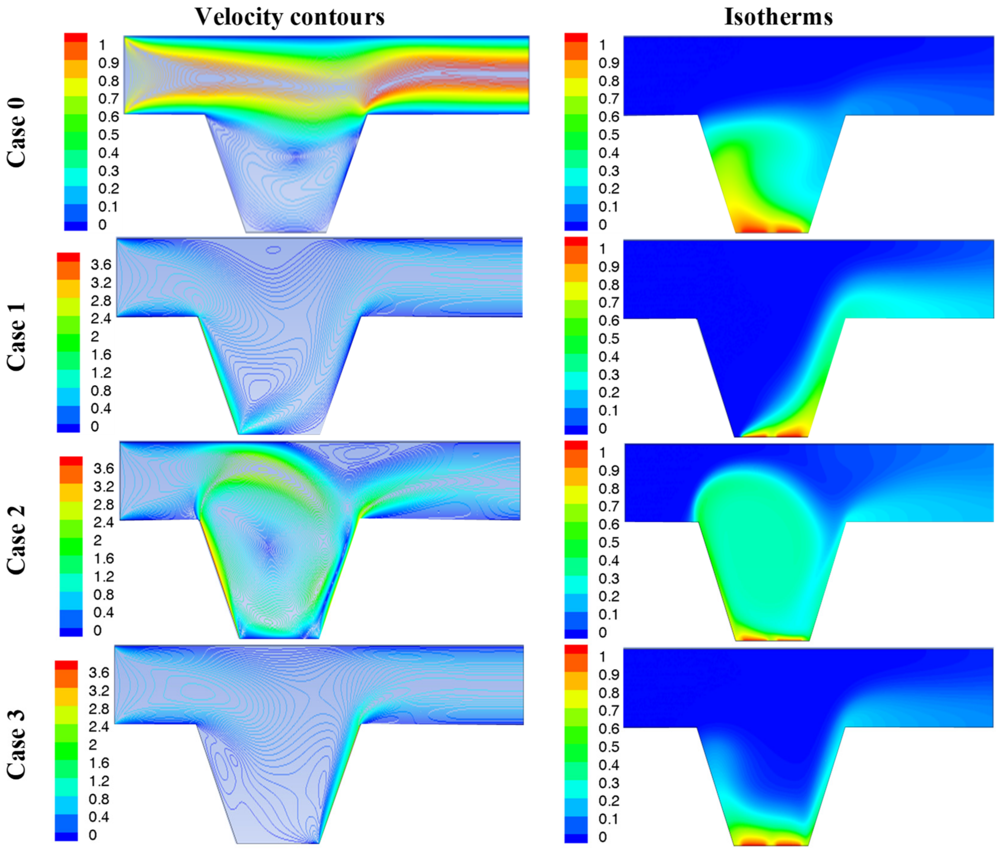
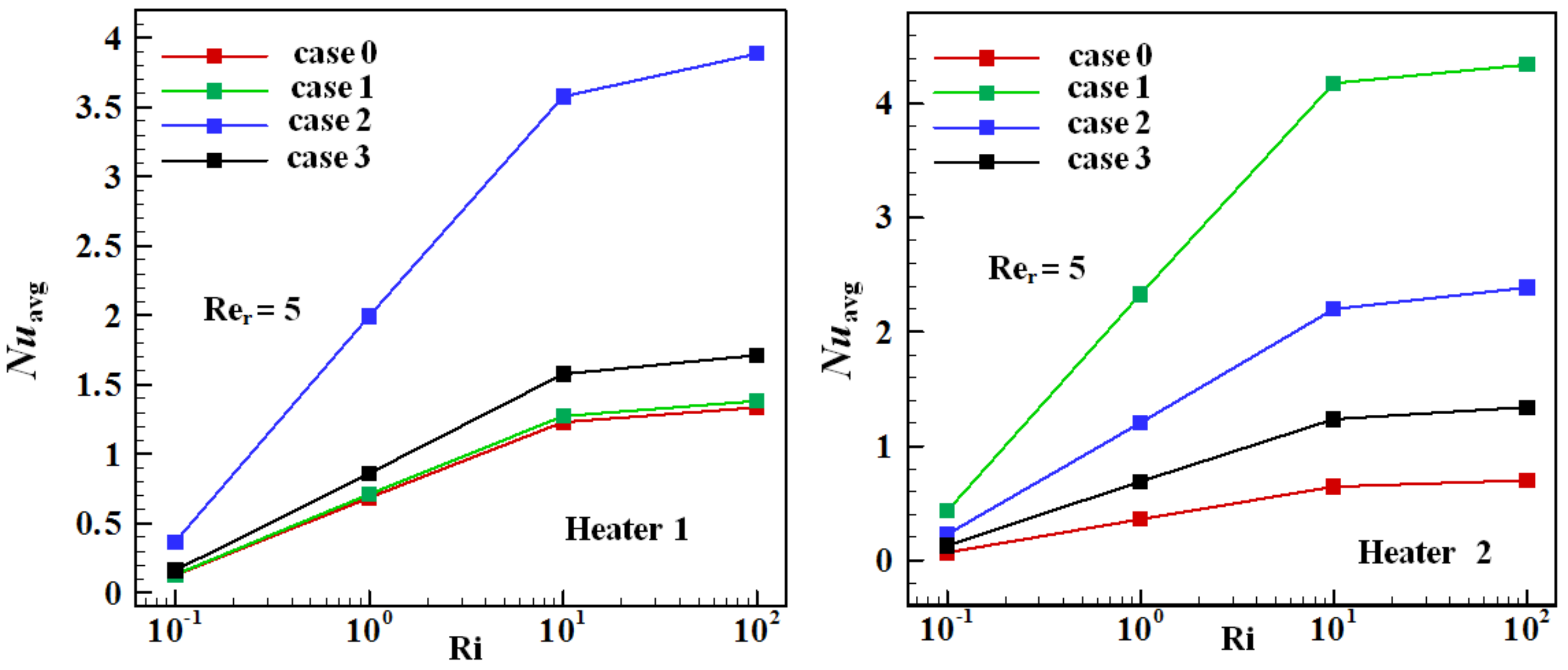
  • Case 0: all the cavity sidewalls are assumed motionless.
  • Case 1: the left sidewall moves downward.
  • Case 2: the left sidewall moves downward and the right one moves upward.
  • Case 3: the right sidewall moves upward.
It is noticed that the thermo-physical characterizes of the air were kept fixed. Furthermore, the approximation of Boussinesq was adopted to solve the dependency of the density temperature.
The dimensional governing equations in Cartesian coordinates are presented hereinafter [29]:
The continuity equation:
U X + V Y = 0
The momentum equations in both X and Y directions are written as:
In the X-direction:
U U X + V U Y = P X + 1 R e i n 2 U X 2 + 2 U Y 2
In the Y-direction:
U V X + V V Y = P Y + 1 R e i n 2 V X 2 + 2 V Y 2 + R i θ
The energy equation is given by:
U θ X + V θ Y = ( 1 P r . R e i n ) ( 2 θ X 2 + 2 θ Y 2 )
where
X , Y = x , y H ,   U , V = u , v u i n ,   θ = T T c T h T c , P = p ρ u i n 2 , R e i n = ρ u i n H μ ,   P r = ν α ε = L H H   and   R i = G r R e i n 2 = g H β ( T h T c ) u i n 2
It must be mentioned that the natural convection effect is due to the buoyancy force generated by the hot and cold temperatures. However, the forced convection is due to two effects. The first one comes from the airflow inside the duct, and the second one is due to the movement of the cavity sidewall(s).
The Nuavg was calculated after integrating the Nuloc at each heater and is expressed as:
N u a v ) 1 = 1 L h 1 0 L h 1 ( N u ) x d X ,   N u a v ) 2 = 1 L h 2 0 L h 2 ( N u ) x d X
where ( N u ) x is the Nuloc and it is given by:
( N u ) x = h x L h k where h x = Q T h ( x ) T i n
Moreover, the Reynolds number ratio can be defined as:
R e r = R e L i d R e i n = u L i d u i n where R e L i d = ρ u L i d H μ
where ( R e L i d ) is the Reynolds number based on the lid-driven velocity.
The boundary conditions are given by:
Duct Entrance: x = 0, HyH + D, θ = 0, uin = 1
Duct Exit : x = 5 H , H y H + D , θ X = U X = V Y = 0 , P = 0
On each discrete heat source : θ = 1 , otherwise θ n = 0
No-slip boundary condition is applied to the fixed walls: U = V = 0.

3. Validation and Grid Independency Analysis

During the current research, ANSYS software was used to compute the numerical results. The first challenge is to convert the partial differential equations (i.e., Equations (1)–(4)) with their related boundary conditions into linear algebraic equations to solve them easily. The physical domain of the problem is discretized into several elements linked by nodes and represented by algebraic linear equations. The residuals of each conservation equation are computed by substituting the approximations into the Navier stokes equations.
To select the suitable grid size, which is required to reduce the time of the computation, the first step is to check the grid independency. This test was performed by using six different elements numbers for each heat source depending on the different average Nusselt numbers. Six grid sizes were tested at Ri = 0.1, Pr = 0.7, and Re = 100 (see Table 1). It was found that the values of the Nuavg for G3 (50,554 elements) and G4 (42,468 elements) grids are almost identical with a very small error (<0.2%). Therefore, a grid size of G3 (50,554 elements) was selected in the numerical solution due to its time-economy merit and small deviations in the average Nusselt number. In order to check the current work results, the Manca et al. [9] case is resolved by the present model as presented in Figure 2, and a good concordance between the two results is observed.

4. Results and Discussion

Results of numerical simulation are presented hereinafter by plotting the isotherms, streamlines, and the Nuavg for different parameters. These parameters are Ri number (0.1 ≤ Ri ≤ 100), Re (1 ≤ Rer ≤ 5), and various directions of the lid-driven sidewall(s) of the cavity. It is noticed here that the constant parameters are dimensionless heat source length ε (ε = 0.2), Pr = 0.71, and Re = 100.

5. Effects of Various Cases of the Lid-Driven Sidewalls

The velocity contours and isotherms distribution for different cases of the sidewall’s movement at Ri = 1 and Rer = 5 are presented in Figure 3 when the cavity sidewalls are assumed motionless (i.e., case 0). Therefore, both the flow and heat transfer in the duct-enclosure assembly were influenced by two impacts. The first effect comes back to the forced convection coming from the airflow inside the duct, while the second one is due to the natural convection rising from the two heaters’ sides. The results indicated that the airflow could not enter the cavity easily by cause of the high effect of the shear force inside the duct. For this reason, the mixing between the flow fields inside the duct and the cavity is not good enough in this case, and they seem to be separated from each other. The same thing can be seen for the thermal field. The isotherm contours refer that they are similar to each other in both the duct and the cavity, and no effective heat transfer occurs between them in this case. For Case 1, the left sidewall of the cavity moves downward. Therefore, forced convection, in this case, comes from two different impacts. The first effect is to come back to shear force initiated by the movement of the left sidewall of the enclosure, while the second one is due to the airflow in the duct. The impact of the natural convection remains the same as mentioned in Case 0. Therefore, the velocity contours move towards the left sidewall of the enclosure. Since the impact of the forced convection provoked adjacent to this wall becomes more significant than that observed in Case 0. This leads to producing a counterclockwise circulation inside the cavity, as shown in Figure 3. Moreover, it can be observed that the velocity contours inside the enclosure switch their behavior from a primary single vortex, which was noticed at Case 0, to multi-vortices at Case 1. With respect to the thermal field, we found that there is an isothermal region near the left sidewall of the cavity. This behavior comes back to the movement of this wall which helps the inlet cold air to enter the cavity. This accompanies pushing the temperature gradient to the right sidewall of the cavity until it reaches the exit length of the duct. For Case 2, the left sidewall moves downward, and the right one moves upward. This movement of the two sidewalls of the cavity helps the hot air adjacent to the two discrete heat sources to move upward and mix efficiently with the cold air inside the duct. This behavior can be reflected in the major rotating vortices in the core of the duct-cavity assembly. From another side, it can be observed from the isotherm contours that there is a good heat transfer mixing between the air in the duct-cavity assembly. This can also be insured from a plume-like behavior of isotherms. In this case, it can be concluded that the extra effect of the shear force comes from the lid-driven right wall of the enclosure; besides, the lid-driven left one has a clear impact on the flow and thermal fields inside the duct-cavity assembly. Furthermore, the temperature gradients try to extend at the entrance of the exit length of the duct. Therefore, more energy will be transferred from the cavity to the exit length of the duct, making the air in it become hotter (Case 2) compared with other considered cases. In Case 3, the right sidewall moves upward. Therefore, the velocity contours move towards the right sidewall of the cavity. In this case, the pattern of the velocity contours is similar to that noticed for Case 1. The major difference between them is that the vortices move towards the lid-driven wall in each case. From isotherm contours, we observed that the entering cold air into the duct was drawn into the cavity and accumulated near the lid-driven right sidewall of it. Therefore, it can be deduced from the results discussed above that the movement of the cavity sidewall(s) has a significant impact on the flow structure and temperature field inside it.

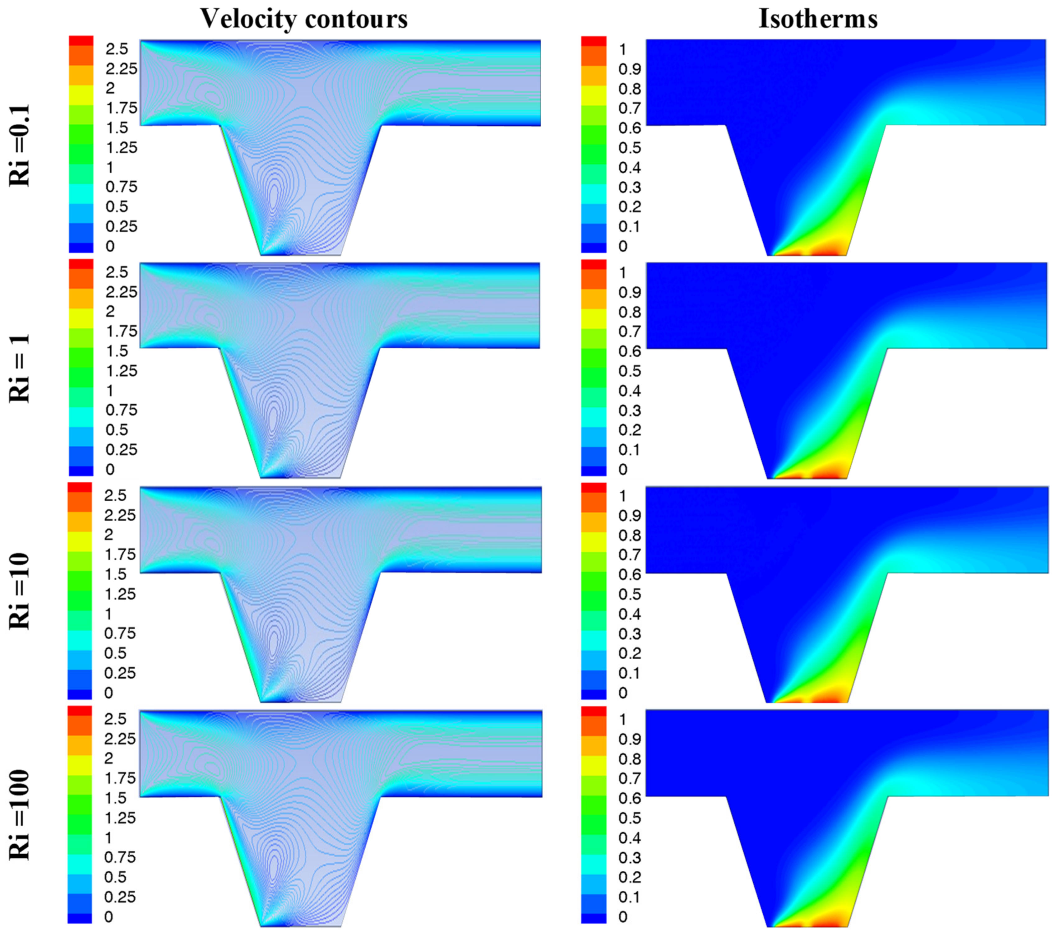
6. Effects of the Richardson Number

Figure 4 displays the velocity contours and isotherms distribution for different Richardson numbers at Rer = 3 and Case 1. As mentioned previously, in Case 1, the left sidewall moves downward only. It is important to refer that the results in this figure are drawn when the Reynolds number ratio equals three (i.e., Rer = 3). This means that the lid-driven left sidewall of the cavity moves by three times more than the inlet air velocity (uLid = 3 uin). It was found that the velocity contours begin to move towards the lid-driven left sidewall of the cavity when Ri = 0.1. This comes back to the dominance of the shear force for a small level of the Ri and Re numbers is high. Therefore, the shear force becomes greater than the buoyancy force. This comes back to the increase in the airflow velocity inside the duct. This leads to making the forced convection greater than the natural one inside the cavity. With respect to the thermal field, it was found that the temperature gradient is governed by the forced convection only at Ri = 0.1. Therefore, the effect of convection currents that comes from the temperature gradients between the cold air inside the duct and the hot air adjacent to the discrete heat sources is slight. When Ri = 1, the free convection impact becomes equivalent to the forced convection impact, or in another meaning, both the effects of the shear and buoyancy forces become comparable. Moreover, the velocity contours become closer to each other. This indicates that the mixed convection effect is dominant at Ri = 1. Now, for Ri ≥ 10, or when the Re is low, the natural convection becomes greater than the forced convection. This comes back to the severe impact of the buoyancy force when the Ri is high. This leads to a decrease in the airflow velocity inside the duct and causes, as a result, a clear weakness in the shear force effect. In other words, both the flow and thermal field inside the enclosure were governed only by the temperature difference between the cold air entering the duct and the hot air adjacent to the two discrete heat sources embedded in the bottom wall. Therefore, the effect of the lid-driven sidewall becomes negligible. For this reason, it can be seen a high similarity between the flow and thermal fields at Ri = 10 and Ri = 100, respectively.

7. Effects of the Reynolds Number Ratio

Figure 5 shows the velocity contours and temperature distribution for different Reynolds number ratios at Ri = 10 and Case 3. As mentioned earlier, in Case 3, the right sidewall moves upward only. When the Reynolds number ratio is unity (Rer = 1), the right sidewall of the cavity moves with a velocity equal to the inlet air velocity (i.e., uLid = uin). Therefore, the effect of the lid-driven wall on the velocity and temperature contours is very weak. For this reason, both the flow and thermal fields pattern seem similar to that noticed and discussed previously in Figure 3 (i.e., Case 0). Now, when the Reynolds number ratio increases (i.e., Rer = 3 and 5), or in other words, when the velocity of the lid-driven wall becomes more than the inlet air velocity, a clear difference in both the flow and thermal pattern can be observed. The flow pattern becomes multi-cellular, and the size of the flow vortices begins to increase as the Reynolds number ratio increases. Additionally, an intense accumulation of streamlines near the lid-driven sidewall can be observed. This change in the flow pattern can be returned to the increase in the speed of the lid-driven wall. With respect to the thermal field, it was found that as the Reynolds number ratio increases, the cold air in the duct begins to enter more rapidly inside the cavity and passes over the discrete heat sources carrying more energy before it leaves. This, of course, improves the heat transfer mechanism inside the duct-cavity assembly.

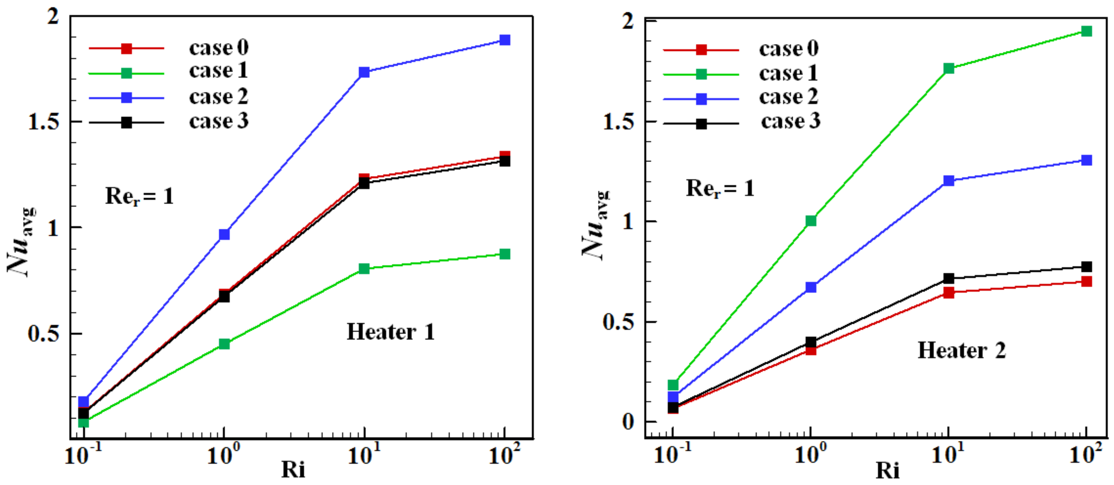
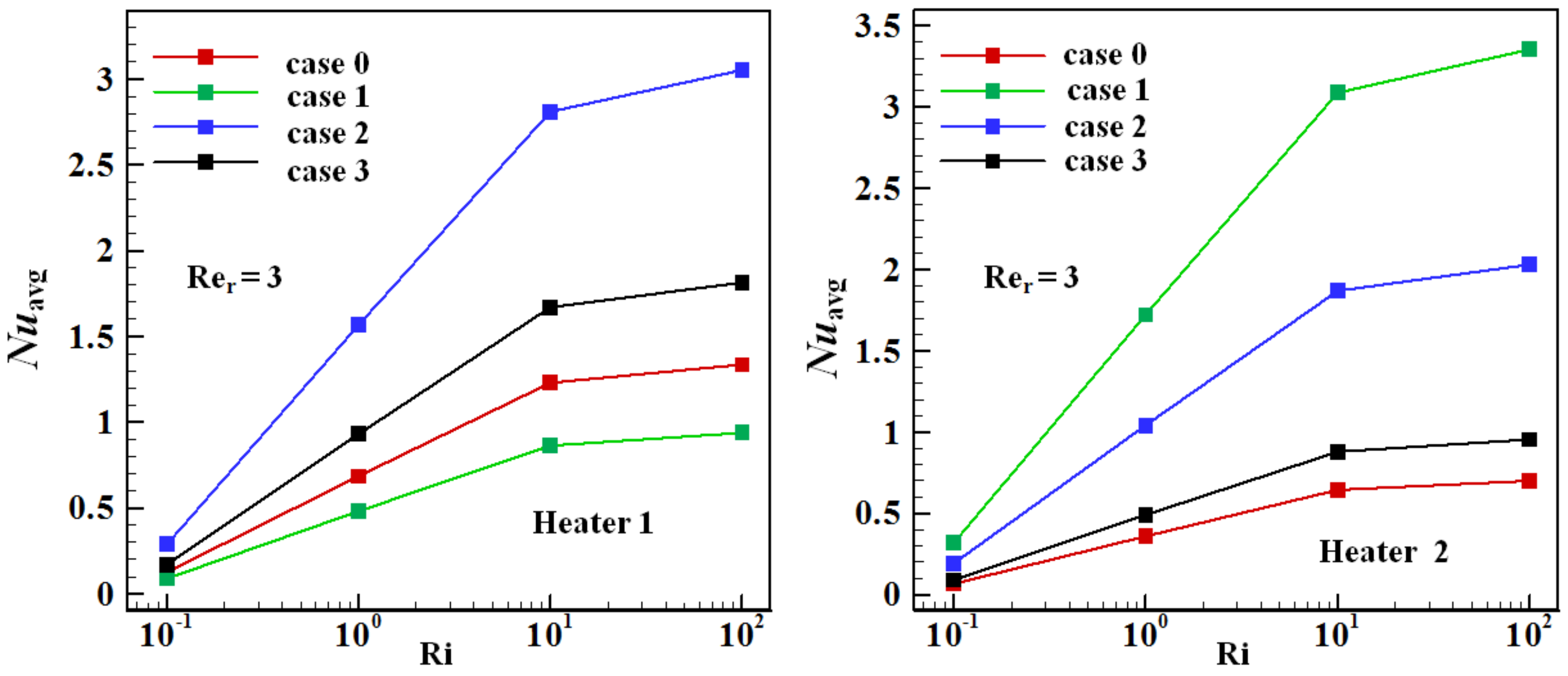
8. Average Nusselt Number Results

Figure 6 and Figure 7 indicate, respectively, the average Nusselt number variation with the Richardson number for the two heaters’ positions and for different cases of the moving wall and Rer = 1 and 3. For all considered cases, the Nuavg increase by the increase in the Ri number. As a result, the Nuavg reaches its peak value at (Ri = 100), and this result is similar to all the considered cases. This is due to the high increase in the contribution of the natural convection in thermal performance, which leads to an increase in the temperature gradient and, as a result, increases the Nuavg. Furthermore, the maximum value of Nuavg arises for heater 1—Case 2 and the minimum value for heater 1—Case 1. For heater 2, the maximum value of the Nuavg occurs at Case 1, while the minimum value of it occurs at Case 0. Therefore, Nuavg was enhanced by the movement of cavity sidewall(s) compared with stationary walls. This is due to the shear friction between the air and the lid-driven sidewalls, which improves the heat transfer inside the duct-enclosure assembly. It is useful to mention also that the Nuavg enhances as the Re number ratio enhances. Therefore, its value at Rer = 3 is greater than its value at Rer = 1 since the rise in Re number ratio causes to enhance the Re number based on the lid velocity and enhances the Nuavg. The same behavior discussed previously can be observed in Figure 8 or when the lid-driven wall(s) of the cavity moves by five times more than the inlet air velocity (uLid = 5 uin or Rer = 5). The only remarkable difference is that the minimum value of the Nuavg for heater 1 occurs at Case 0, and it is very close to the corresponding results at Case 1. Moreover, it can be deduced from the results above that using heater 2 is better than using heater 1 due to the high values of the Nuavg. This result is approved for all considered cases and (Re)ratio.

9. Conclusions

During this study, four cases for lid driven were simulated, and some important conclusions were deduced:
-
For Case 0, the mixing between the flow and thermal fields inside the duct and the enclosure is not good enough, and they seem to be separated from each other.
-
For Cases 1 and 3, the flow field pattern becomes multi-cellular, and an isothermal region near the lid-driven sidewall of the cavity is noticed.
-
For Case 2, the combination between the flow and thermal fields inside the duct and the cavity is efficient due to the movement of both sidewalls of the cavity.
The effect of the dimensionless numbers was significant, in fact:
-
The Reynolds number ratio and the movement of the cavity sidewall(s) generated a significant impact on the velocity and temperature contours inside the cavity itself.
-
The effect of the lid-driven sidewall(s) of the cavity and the forced convection became dominant for low values of Richardson number. Additionally, the free convection impact was critical for high Richardson values.
-
The Nuavg increases as the Richardson number and Re number ratio increase.
-
The Nuavg was enhanced for moving cavity sidewall(s) compared with stationary walls.
-
The maximum values of the Nuavg can be found for Case 1 and heater 2.
-
Heater 1 is preferable and recommended when both sidewalls of the cavity are considered to be moving, while heater 2 is better when one sidewall is moved.

Author Contributions

Conceptualization, F.M.-O., H.L., A.K.H. and M.O.; methodology, F.M.-O., H.L. and L.K.; software, F.M.-O. and H.L.; validation, F.M.-O., H.L. and A.K.H.; formal analysis, A.A., L.K. and U.B.; investigation, H.L., A.K.H. and M.O.; resources, M.O.; data curation, A.K.H., M.O. and A.A.; writing—original draft preparation, F.M.-O., H.L., A.K.H., M.O., A.A., L.K. and U.B.; writing—review and editing, F.M.-O., H.L., A.K.H., M.O., A.A., L.K. and U.B.; project administration, M.O.; funding acquisition, M.O. All authors have read and agreed to the published version of the manuscript.

Funding

This project was funded by the Deanship of Scientific Research (DSR), King Abdulaziz University, Jeddah, under grant No. (D-234-305-1442). The authors, therefore, gratefully acknowledge DSR’s technical and financial support.

Conflicts of Interest

The authors declare no conflict of interest.

Nomenclature

DHeight or diameter of the duct (m)
gGravitational acceleration (m/s2)
GrGrashof number
hConvection heat transfer coefficient (W/m2·C)
HHeight and width of the cavity (m)
LExit length (m)
LHLength of the localized heat source (m)
nNormal vector
NuNusselt number
PDimensionless pressure
pPressure (N/m2)
PrPrandtl number
QHeat flux (W/m2)
ReReynolds number
RerReynolds number ratio
RiRichardson number
TTemperature (°C)
UDimensionless velocity component in X-direction
uVelocity component in x-direction (m/s)
VDimensionless velocity component in Y-direction
vVelocity component in y-direction (m/s)
XDimensionless coordinate in the horizontal direction
xCartesian coordinate in the horizontal direction (m)
YDimensionless coordinate in the vertical direction
yCartesian coordinate in the vertical direction (m)
Greek symbols
θDimensionless temperature
β Thermal expansion coefficient (1/K)
εDimensionless length of the localized heat source
α Thermal diffusivity (m2/s)
μ Dynamic viscosity (kg/m∙s)
ν Kinematic viscosity (m2/s)
ρ Density (kg/m3)
Subscripts
avgAverage
cCold
hHot
inInlet
Lid Lid-driven

References

  1. Ismael, M.A.; Hussein, A.K.; Mebarek-Oudina, F.; Kolsi, L. Effect of Driven Sidewalls on Mixed Convection in Open Trapezoidal Cavity with Channel. J. Heat Transf. 2020, 142, 082601. [Google Scholar] [CrossRef]
  2. Mebarek-Oudina, F.; Bessaïh, R. Numerical Simulation of Natural Convection Heat Transfer of Copper-Water Nanofluid in a Vertical Cylindrical Annulus with Heat Sources. Thermophys. Aeromechanics 2019, 26, 325–334. [Google Scholar] [CrossRef]
  3. Mebarek-Oudina, F.; Laouira, H.; Aissa, A.; Hussein, A.K.; El Ganaoui, M. Convection Heat Transfer Analysis in a Channel with an Open Trapezoidal Cavity: Heat Source Locations effect. MATEC Web Conf. 2020, 330, 01006. [Google Scholar] [CrossRef]
  4. Mebarek-Oudina, F. Convective Heat Transfer of Titania Nanofluids of different base fluids in Cylindrical Annulus with discrete Heat Source. Heat Transf. Asian Res. 2019, 48, 135–147. [Google Scholar] [CrossRef] [Green Version]
  5. Chabani, I.; MebarekOudina, F.; Ismail, A.I. MHD Flow of a Hybrid Nano-fluid in a Triangular Enclosure with Zigzags and an Elliptic Obstacle. Micromachines 2022, 13, 224. [Google Scholar] [CrossRef]
  6. Gourari, S.; Mebarek-Oudina, F.; Hussein, A.K.; Kolsi, L.; Hassen, W.; Younis, O. Numerical study of natural convection between two coaxial inclined cylinders. Int. J. Heat Technol. 2019, 37, 779–786. [Google Scholar] [CrossRef]
  7. Esfe, M.; Saedodin, S.; Malekshah, E.; Babaie, A.; Rostamian, H. Mixed convection inside lid-driven cavities filled with nanofluids: A comprehensive review. J. Therm. Anal. Calorim. 2019, 135, 813–859. [Google Scholar] [CrossRef]
  8. Izadi, S.; Armaghani, T.; Ghasemiasl, R.; Chamkha, A.; Molana, M. A comprehensive review on mixed convection of nanofluids in various shapes of enclosures. Powder Technol. 2019, 343, 880–907. [Google Scholar] [CrossRef]
  9. Manca, O.; Nardini, S.; Khanafer, K.; Vafai, K. Effect of heated wall position on mixed convection in a channel with an open cavity. Numer. Heat Transf. Part A 2003, 43, 259–282. [Google Scholar] [CrossRef]
  10. Brown, N.; Lai, F. Correlations for combined heat and mass transfer from an open cavity in a horizontal channel. Int. Commun. Heat Mass Transf. 2005, 32, 1000–1008. [Google Scholar] [CrossRef]
  11. Leong, J.; Brown, N.; Lai, F. Mixed convection from an open cavity in a horizontal channel. Int. Commun. Heat Mass Transf. 2005, 32, 583–592. [Google Scholar] [CrossRef]
  12. Stiriba, Y. Analysis of the flow and heat transfer characteristics for assisting incompressible laminar flow past an open cavity. Int. Commun. Heat Mass Transf. 2008, 35, 901–907. [Google Scholar] [CrossRef]
  13. Stiriba, Y.; Grau, F.; Ferre, J.; Vernet, A. A numerical study of three-dimensional laminar mixed convection past an open cavity. Int. J. Heat Mass Transf. 2010, 53, 4797–4808. [Google Scholar] [CrossRef]
  14. Wong, K.; Saeid, N. Numerical study of mixed convection on jet impingement cooling in an open cavity filled with porous medium. Int. Commun. Heat Mass Transf. 2009, 36, 155–160. [Google Scholar] [CrossRef]
  15. Rahman, M.; Parvin, S.; Saidur, R.; Rahim, N. Magnetohydrodynamic mixed convection in a horizontal channel with an open cavity. Int. Commun. Heat Mass Transf. 2011, 38, 184–193. [Google Scholar] [CrossRef]
  16. Rahman, M.; Oztop, H.; Rahim, N.; Saidur, R.; Al-Salem, K.; Amin, N.; Mamun, M.; Ahsan, A. Computational analysis of mixed convection in a channel with a cavity heated from different sides. Int. Commun. Heat Mass Transf. 2012, 39, 78–84. [Google Scholar] [CrossRef]
  17. Rahman, M.; Oztop, H.; Saidur, R.; Mekhilef, S.; Al-Salem, K. Finite element solution of MHD mixed convection in a channel with a fully or partially heated cavity. Comput. Fluids 2013, 79, 53–64. [Google Scholar] [CrossRef]
  18. Rahman, M.; Parvin, S.; Rahim, N.; Hasanuzzaman, M.; Saidur, R. Simulation of mixed convection heat transfer in a horizontal channel with an open cavity containing a heated hollow cylinder. Heat Transf. Asian Res. 2012, 41, 339–353. [Google Scholar] [CrossRef]
  19. Stiriba, Y.; Ferre, J.; Grau, F. Heat transfer and fluid flow characteristics of laminar flow past an open cavity with heating from below. Int. Commun. Heat Mass Transf. 2013, 43, 8–15. [Google Scholar] [CrossRef]
  20. Abdelmassih, G.; Vernet, A.; Pallares, J. Numerical simulation of incompressible laminar flow in a three-dimensional channel with a cubical open cavity with a bottom wall heated. J. Physics. Conf. Ser. 2012, 395, 1–7. [Google Scholar] [CrossRef]
  21. Azad, A.; Munshi, M.; Rahman, M.; Chowdhury, M. Analysis of combined convection in an open cavity under constant heat flux boundary conditions and magnetic field using finite element method. J. Sci. Res. 2014, 6, 243–256. [Google Scholar]
  22. Burgos, J.; Cuesta, I.; Saluena, C. Numerical study of laminar mixed convection in a square open cavity. Int. J. Heat Mass Transf. 2016, 99, 599–612. [Google Scholar] [CrossRef]
  23. Zamzari, F.; Mehrez, Z.; El-Cafsi, A.; Belghith, A.; le Quéré, P. Numerical investigation of entropy generation and heat transfer of pulsating flow in a horizontal channel with an open cavity. J. Hydrodyn. 2017, 29, 632–646. [Google Scholar] [CrossRef]
  24. Sabbar, W.; Ismael, M.; Al-Mudhaffar, M. Fluid-structure interaction of mixed convection in a cavity-channel assembly of flexible wall. Int. J. Mech. Sci. 2018, 149, 73–83. [Google Scholar] [CrossRef]
  25. Sivasankaran, S.; Al-Zaharani, F.; Al-Shomrani, A. Effect of baffle size and thermal boundary conditions on mixed convection flow in a channel with cavity. J. Phys. Conf. Ser. 2018, 1139, 1–8. [Google Scholar] [CrossRef]
  26. Yasin, N.; Jehhef, K.; Shaker, A. Assessment of the baffle effects on the mixed convection in open cavity. Int. J. Mech. Mechatron. Eng. 2018, 18, 1–14. [Google Scholar]
  27. Contreras, H.; Trevino, C.; Lizardi, J.; Martinez-Suastegui, L. Stereoscopic TR-PIV measurements of mixed convection flow in a vertical channel with an open cavity with discrete heating. Int. J. Mech. Sci. 2019, 150, 427–444. [Google Scholar] [CrossRef]
  28. Cardenas, V.; Trevino, C.; Rosas, I.; Martinez-Suastegui, L. Experimental study of buoyancy and inclination effects on transient mixed convection heat transfer in a channel with two symmetric open cubic cavities with prescribed heat flux. Int. J. Therm. Sci. 2019, 140, 71–86. [Google Scholar] [CrossRef]
  29. Laouira, H.; Mebarek-Oudina, F.; Hussein, A.K.; Kolsi, L.; Merah, A.; Younis, O. Heat transfer inside a horizontal channel with an open trapezoidal enclosure subjected to a heat source of different lengths. Heat Transf. Asian Res. 2020, 49, 406–423. [Google Scholar] [CrossRef]
  30. Fusegi, T. Numerical study of convective heat transfer from periodic open cavities in a channel with oscillatory through flow. Int. J. Heat Fluid Flow 1997, 18, 376–383. [Google Scholar] [CrossRef]
  31. Manca, O.; Nardini, S.; Naso, V.; Pitzolu, R. Mixed convection in a channel with an open cavity below, Paper ID-142. In Proceedings of the 7th Fluid Control, Measurements and Visualization-FLUCOME, Sorrento, Italy, 25–28 August 2003. [Google Scholar]
  32. Manca, O.; Nardini, S.; Vafai, K. Experimental investigation of mixed convection in a channel with an open cavity. Exp. Heat Transf. 2006, 19, 53–62. [Google Scholar] [CrossRef]
  33. Manca, O.; Nardini, S.; Vafai, K. Experimental investigation of opposing mixed convection in a channel with an open cavity below. Exp. Heat Transf. 2008, 21, 99–114. [Google Scholar] [CrossRef]
  34. Marzougui, S.; Mebarek-Oudina, F.; Mchirgui, A.; Magherbi, M. Entropy Generation and Heat transport of Cu-water Nanoliquid in Porous lid-driven Cavity through Magnetic Field. Int. J. Numer. Methods Heat Fluid Flow, 2021; in press. [Google Scholar] [CrossRef]
  35. Buonomo, B.; Foglia, G.; Manca, O.; Nardini, S. Numerical study on mixed convection in a channel with an open cavity filled with porous media. In Proceedings of the 5th European Thermal—Sciences Conference, Eindhoven, The Netherlands, 18–22 May 2008; pp. 1–8. [Google Scholar]
  36. Aminossadati, S.; Ghasemi, B. A numerical study of mixed convection in a horizontal channel with a discrete heat source in an open cavity. Eur. J. Mech. B/Fluids 2009, 28, 590–598. [Google Scholar] [CrossRef]
  37. Rahman, M.; Saidur, R.; Rahim, N. Conjugated effect of joule heating and magneto-hydrodynamic on double-diffusive mixed convection in a horizontal channel with an open cavity. Int. J. Heat Mass Transf. 2011, 54, 3201–3213. [Google Scholar] [CrossRef]
  38. Rahman, M.; Oztop, H.; Ahsan, A.; Kalam, M.; Billah, M. MHD mixed convection in a channel with a triangular cavity. Numer. Heat Transf. Part A 2012, 61, 268–282. [Google Scholar] [CrossRef]
  39. Buonomo, B.; Cresci, G.; Manca, O.; Mesolella, P.; Nardini, S. Transient mixed convection in a channel with an open cavity filled with porous media. J. Phys. Conf. Ser. 2012, 395, 1–8. [Google Scholar] [CrossRef]
  40. Selimefendigil, F. Numerical analysis and POD based interpolation of mixed convection heat transfer in horizontal channel with cavity heated from below. Eng. Appl. Comput. Fluid Mech. 2013, 7, 261–271. [Google Scholar] [CrossRef] [Green Version]
  41. Zamzari, F.; Mehrez, Z.; El-Cafsi, A.; Belghith, A. Entropy generation and mixed convection in a horizontal channel with an open cavity. Int. J. Exergy 2015, 17, 219–239. [Google Scholar] [CrossRef]
  42. Abdelmassih, G.; Vernet, A.; Pallares, J. Steady and unsteady mixed convection flow in a cubical open cavity with the bottom wall heated. Int. J. Heat Mass Transf. 2016, 101, 682–691. [Google Scholar] [CrossRef]
  43. Garcia, F.; Trevino, C.; Lizardi, J.; Martinez-Suastegui, L. Numerical study of buoyancy and inclination effects on transient mixed convection in a channel with two facing cavities with discrete heating. Int. J. Mech. Sci. 2019, 155, 295–314. [Google Scholar] [CrossRef]
Figure 1. The physical problem with boundary conditions.
Mathematics 10 00929 g001
Figure 2. Comparison of temperature field and flow structure with the work of Manca et al. [9].
Mathematics 10 00929 g002
Figure 3. Dimensionless velocity contours and isotherms for various cases of the sidewalls movement at Ri = 1 and Rer = 5.
Mathematics 10 00929 g003
Figure 4. Dimensionless velocity contours and isotherms distribution for different Richardson numbers at Rer = 3 and Case 1.
Mathematics 10 00929 g004
Figure 5. Dimensionless velocity contours and isotherms distribution for various Reynolds number ratios at Ri = 10 and Case 3.
Mathematics 10 00929 g005
Figure 6. Nuavg via the Ri at two heaters for different cases of the moving wall and Rer = 1.
Mathematics 10 00929 g006
Figure 7. Variation of Nuavg versus Ri at the two heaters for various cases of the moving wall and Rer = 3.
Mathematics 10 00929 g007
Figure 8. Nuavg via the Ri at two heaters for various cases of the moving wall and Rer = 5.
Mathematics 10 00929 g008
Table 1. Nuavg via various grids at Ri = 0.1, Re = 100, and Pr = 0.7.
Nuav
GridHeater 1Heater 2
G1 (75125)0.125839980.06460179
G2 (60996)0.114289220.0563892
G3 (50554)0.126419780.06621620
G4 (42468)0.124979430.06409777
G5 (36276)0.121443830.060833
G6 (31296)0.116718960.05772451
Publisher’s Note: MDPI stays neutral with regard to jurisdictional claims in published maps and institutional affiliations.

