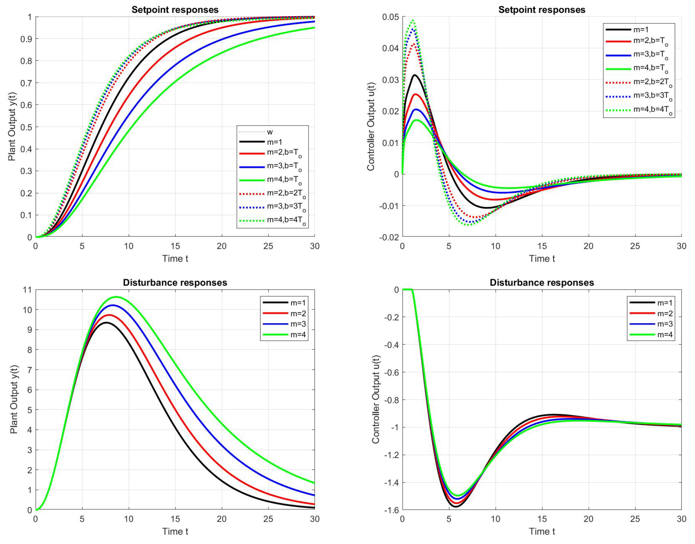
The use of PPM, which allows us to overcome the computational difficulties of analytical design, has not produced significant changes in transients; therefore, we try to look at the problem of optimal setting of PID controllers from a broader perspective and include other alternative approaches. Although PID controllers are very commonly used for disturbance compensation, their evaluation and comparison with other alternative methods of reconstruction and disturbance compensation, such as the “modern” state-space approach [
44,
45],“postmodern” disturbance observer (DOB) based control [
46], active disturbance rejection control (ADRC) [
34,
47], or intelligent PID control (referred to as model-free control) [
48], is still pending.
A Brief History of Series and Parallel PID Control
In explaining the fundamental problem of the transition from PD to PID control, which causes the large increase in sensitivity to measurement noise and a significant decrease in the speed of transient responses experimentally demonstrated in [
31], we must first understand the associated change in the functionality of the PID controller, in which the ability to eliminate the effects of constant disturbances plays a key role. The study of the effectiveness of automatic control with disturbance compensation has been the subject of intense research for decades [
34,
45].
At the beginning of 20th century, two branches of automatic process control development emerged. The first was more practically oriented, the second investigated the theoretical aspects of automatic control. One of the pioneers of PID controllers is Elmer Sperry, who as early as 1911 developed an autopilot for ships and aircraft, attempting to imitate the behaviour of a human operator. The theoretical analysis of effective automatic control of ships was carried out in 1922 by Nicolas Minorsky, whose research also based on an analysis of the activities of the human operator, which he converted into mathematical operations and justified the need for proportional, integral and derivative actions of the controller [
35]; however, the problem did not end with the naming of the necessary components, but rather overshadowed the need to divide the two levels of the proposal: stabilisation of the basic system and counteracting of disturbances involving deviations from the basic system [
34].
First of all, it should be recalled that the first PI controllers, which appeared in 1935–1938 as the pneumatic regulators “Fulscope” (by Taylor Instrument Companies, originally called “pre-act”) and “Stabilog” (by Foxboro Instrument, known as “Hyper-reset”, [
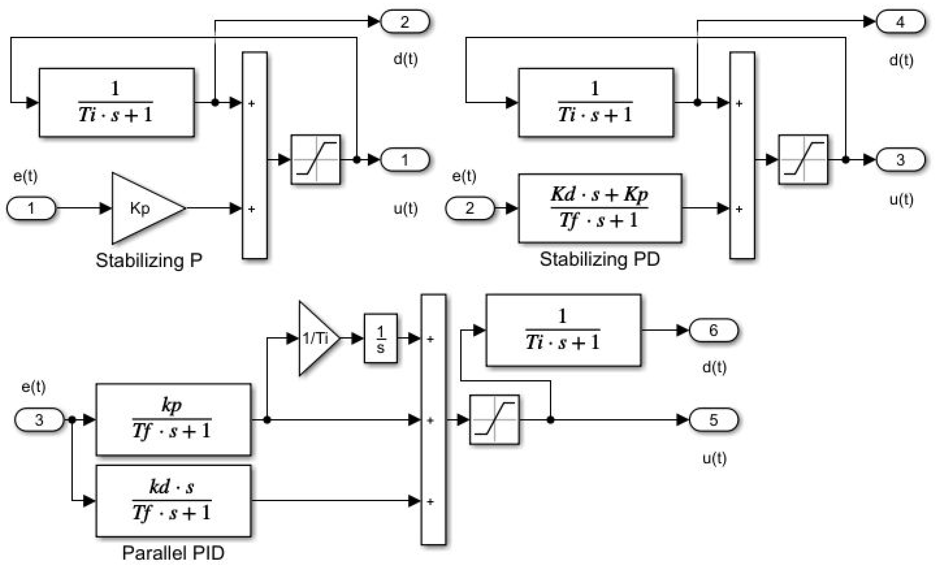
49]) played an important role. They arose from the generalisation of older controllers called “automatic reset”, in which the output of a stabilising P controller was changed by introducing a positive feedback via a delay with the time constant
. Its operation can be easily explained using the example of the control of integrating systems, where the input of the integrator must be zero in steady state. This means that the controller output in steady state must be equal to the negative value of a constant input disturbance. Thus, to reconstruct and compensate the disturbance, it is sufficient to wait until the next steady-state reached with a stabilising controller (P or PD), and then subtract the obtained disturbance value from the previous output of the stabilising controller. In view of the opposite signs of the steady-state controller output and the reconstructed disturbance and the need to compensate for the disturbance by subtracting it from the controller output, this means adding the value of the steady-state control signal to the controller output. Such a procedure means the introduction of positive feedback. If one wants to avoid the necessity of a steady state testing, it is sufficient to introduce such a feedback with a sufficiently long delay
, which is significantly longer than the dominant time constant of the stabilised loop transients (see
Figure 15).
In the later development of the theory of automatic control, the use of the older (and possibly more concise) terminology was abandoned and new names for the series PI and PID controllers were introduced instead. Although the structure of series PI and PID controller can be found in numerous textbooks, its characteristic as a stabilising controller supplemented by a disturbance observer went unnoticed. The companies that developed series PID controllers were not motivated to explain its essence, but rather sought patent protection for their solutions, which are determined by aspects other than the explanation of functionality. The theoretical “branch” was content with naming the components that the PID controller introduces into to the circuit and their secondary effect on the achieved performance as the primary mission of the controller. Even if an attempt is made to present PID controllers as an industry standard, this is not possible due to the existence of various controller structures, of which the best known are series and parallel controllers. Let us just remember that in order to achieve the same loop dynamics (to obtain the same controller transfer function), it is generally necessary to calculate different series and parallel PID parameters, when (using the indices “s” and “p”) it must be true that
The transitions from a series to a parallel controller is always possible according to
The calculation of the series PID parameters from the parallel PID controller according to
is only possible for
.
When designing controllers, we should not forget the fundamental aspects of control design. Just as “every good regulator of a system must be a model of that system” [
50], it should also be true “if the controller is to compensate for disturbances, it must also reconstruct them”. In the case of PID controllers used with piecewise constant input disturbances, this can be verified by calculating the transfer function
In steady state, with , compensation of a constant input disturbance is provided by the controller output.
Since the mission of the series PID controller is also crucial for the successful solution of its optimal settings, we summarise it in the following definition.
Definition 1 (Series PI and PID controllers). The series PI and PID controllers are the first historically known disturbance counteracting controllers using DOB that complement the stabilising P and PD controllers by the positive feedback of their output. They can be designed by approximating the steady-state output values of the controller based on integral models, representing the negative values of constant input disturbances. To filter out stabilising transients, the (nearly) steady-state values of the controller output can be achieved using low-pass filters with sufficiently long (integral) time constant .
Remark 5 (Compactness of the series PID controller)
. The reconstructed disturbance signal could also be obtained (see Figure 15) by observing the output of the parallel PID controller through a delay with a sufficiently long time constant (to filter out stabilising transients), but (in contrast to compact series PID controllers), such an observer would require an additional filter transfer function. Furthermore, the use of an integrator in parallel PI and PID controllers is a source of redundant integration called windup. Remark 6 (Limitations on selection). Understanding PID functionality is crucial to understanding why we cannot arbitrarily reduce the integral time constant with respect to the dominant time constant of the loop stabilised by the PD controller (see Remarks 2–4). This assumption can be confirmed by all the above analytical and numerical calculations of the optimal PID controller settings.


