Article

Bending and Buckling of FG-GRNC Laminated Plates via Quasi-3D Nonlocal Strain Gradient Theory

by
Emad E. Ghandourah
1,
Ahmed A. Daikh
2,3,
Abdulsalam M. Alhawsawi
1,
Othman A. Fallatah
1 and
Mohamed A. Eltaher
4,5,*
1
Nuclear Engineering Department, Faculty of Engineering, King Abdulaziz University, P.O. Box 80204, Jeddah 21589, Saudi Arabia
2
Department of Technology, University Centre of Naama, Naama 45000, Algeria
3
Laboratoire d’Etude des Structures et de Mécanique des Matériaux, Département de Génie Civil, Faculté des Sciences et de la Technologie, Université Mustapha Stambouli, Mascara 29000, Algerie
4
Mechanical Design & Production Department, Faculty of Engineering, Zagazig University, Zagazig 44519, Egypt
5
Mechanical Engineering Department, Faculty of Engineering, King Abdulaziz University, P.O. Box 80204, Jeddah 21589, Saudi Arabia
*
Author to whom correspondence should be addressed.
Mathematics 2022, 10(8), 1321; https://doi.org/10.3390/math10081321
Submission received: 2 March 2022 / Revised: 30 March 2022 / Accepted: 12 April 2022 / Published: 15 April 2022
(This article belongs to the Section Engineering Mathematics)

Abstract

:
To improve the structural stiffness, strength and reduce the weight of nanoplate structure, functionally graded (FG) graphene-reinforced nanocomposite (GRNC) laminated plates are exploited in this paper. The bending and buckling behaviors of FG-GRNC laminated nanoplates are investigated by using novel quasi-3D hyperbolic higher order shear deformation plate theory in conjunction with modified continuum nonlocal strain gradient theory, which considered both length and material scale parameters. The modified model of Halpin–Tsai is employed to calculate the effective Young’s modulus of the GRNC plate along the thickness direction, and Poisson’s ratio and mass density are computed by using the rule of mixture. An analytical approach of the Galerkin method is developed to solve governing equilibrium equations of the GRNC nanoplate and obtain closed-form solutions for bending deflection, stress distributions and critical buckling loads. A detailed parametric analysis is carried out to highlight influences of length scale parameter (nonlocal), material scale parameter (gradient), distribution pattern, the GPL weight fraction, thickness stretching, geometry and size of GPLs, geometry of the plate and the total number of layers on the stresses, deformation and critical buckling loads. Some details are studied exclusively for the first time, such as stresses and nonlocality effect.

1. Introduction

Functionally graded materials (FGMs) are a novel class of composite materials that possess a gradual variation of constituents through spatial directions. FGM is proposed to reduce the abrupt local stress concentrations between different layers, and is used as a thermal barrier in aircraft, submarines, space station structures and fusion reactors. It has many enhanced properties, such as higher fracture toughness, improved stress spreading, enhanced thermal resistance and inferior stress intensity factors. They are now developed for general use in various fields of engineering.
Due to the remarkable physical, thermal and mechanical properties of graphene, as well as better dispersion, excellent reinforcing nanofillers and relatively low manufacturing cost, lots of studies have begun to turn their attention towards graphene as a functionally graded graphene-reinforced nanocomposite (FG-GRNC). Chen et al. [1] exploited Timoshenko beam theory and mid-plane stretching to predict the post-buckling and nonlinear vibration of multilayer FG-GRNC including porosity effect. Shen et al. [2,3] modeled and analyzed the thermal bending and post-buckling of GRNC laminated plates resting on an elastic foundation and subjected to in-plane temperature variation. Huang et al. [4] studied nonlinear buckling analysis of FG-GRNC shallow arches with elastic rotational constraints under uniform radial load. Song et al. [5] presented bending and buckling analyses of multilayer FG-GRNC polymer composite plates within the framework of the first-order shear deformation theory. The effective Young’s modulus of the nanocomposites is estimated through the Halpin–Tsai micromechanics model. Garcia-Macias et al. [6] adopted the two-parameter agglomeration model to estimate the agglomeration effects of CNTs as reinforcement in composite structure and presented effects of restacking of graphene sheets on the bending and free-vibration behaviors of composite plates. Dong et al. [7] investigated the buckling behavior of FG-GRNC porous cylindrical shells with spinning motion and subjected to external axial compressive force and radial pressure in frame of first-order shear deformation theory. Daikh and Megueni [8] presented influences of plate aspect ratio, gradient index and the thermal loading conditions on the critical buckling of FGM sandwich plates modeled by the higher-order shear deformation plate theory. Liu et al. [9,10] investigated bending, buckling and vibration behaviors of an initially stressed FG cylindrical shell and circular plate reinforced with nonuniformly distributed graphene platelets (GPLs) using the state-space formulation. Polit et al. [11] presented impacts of different dispersion patterns for the graphene and porosity, shallowness of the curved beam, thickness ratio and platelet geometry on the bending and elastic stability of a higher-order beam with nonlinear stretching. Yang et al. [12] studied nonlinear in-plane buckling of fixed shallow FG-GRNC arches subjected to uniform radial load and temperature field. Mao and Zhang [13] presented influences of electric potential and axial forces on the buckling and post-buckling of FG-GRNC with piezoelectric properties. Anirudh et al. [14] investigated the mechanical response of porous FG-GRNC curved beams by using a trigonometric shear deformation theory and finite element method. Tam et al. [15,16] investigated nonlinear bending, free vibration and buckling characteristics of FG-GRNC beams containing open edge cracks by using the finite element method. Thai et al. [17,18] studied mechanical behaviors of multilayer FG-GRNC plates based on the four-variable refined plate theory and modified couple stress theory. Zhao et al. [19] presented a comprehensive review for FG-GRNC structures including mechanical properties, existing micromechanics models, technical challenges and future research directions. Eltaher et al. [20] exploited finite element method to present the complex phenomena of the elastic and elastoplastic indentation responses of FGMs in the framework of frictional contact mechanics. Rahimi et al. [21] studied bending and vibration behaviors of cylindrical GRNC shell using the state space technique. Shahgholian et al. [22] explored buckling of a porous cylindrical FG-GRNC shell using first-order shear deformation theory. Hamed et al. [23,24] illustrated the effect of in-plane varying compressive force on critical buckling loads and buckling modes of composite laminated and FG porous sandwich beams rested on elastic foundation using unified higher order beam theory. Wang et al. [25] investigated the nonlinear bending of FG-GRNC plate with dielectric permittivity within the framework of first-order shear deformation plate theory. Daikh et al. [26] studied thermal buckling of power and sigmoidal FG sandwich beams based on the higher-order shear deformation beam. Karami and Shahsavari [27] investigated the forced resonant vibration analysis of FG-GRNC doubly curved nano-shells. Four different geometries of the shells namely spherical, elliptical, hyperbolic and cylindrical have been studied, and the Halpin–Tsai model and a rule of mixture are exploited to estimate the effective material properties.
For a nanomechanics analysis, unfortunately the classical approach of continuum mechanics commonly discarded the effects of micro-level and bypassed it altogether by identifying mechanical properties (i.e., Young’s modulus, yield stress, ultimate strength, etc.) directly from macroscopic analysis. When dimensions of the structure are comparable to the material internal length scale, the mechanical behavior of these micro- or nanostructures is highly influenced by the material microstructure. The impact of length scales of microstructures is well proved and described by experiments on nanoscale particular geometries. For that reason, to envisage mechanical responses of structure up to micro and nano size accurately, several continuum mechanics theories have been evolved, such as nonlocal elasticity of Eringen [28,29], strain gradient theory [30,31], couple stress theory [32,33] and surface elasticity theory [34,35] that take into account material length scale parameters.
Nowadays, adopted continuous mechanics theories are recommended to consider the missing contribution of micro/nanoscale by many researchers. Sahmani et al. [36] illustrated the size-dependent nonlinear bending of porous FG-GRNC nanobeam and subjected to the uniform distributed load and an axial compressive load via the nonlocal strain gradient theory of elasticity. Emam et al. [37] studied analytically the post-buckling and vibration response of curved multilayer nanobeams subjected to a pre-stress compressive load by using nonlocal elasticity. Ebrahimi and Barati [38] studied hygro-thermal and size-scale effects on the vibration response of graphene sheets rested on viscoelastic medium by employing nonlocal strain gradient theory. Daikh et al. [39] analyzed analytically the thermal buckling of porous FG sandwich nanoplates resting on a Kerr foundation via nonlocal strain gradient theory. Fattahi et al. [40] developed a nonlocal strain gradient beam model to predict the nonlinear secondary resonance of FG porous micro/nanobeams under periodic excitation by using multiple timescales together with the Galerkin technique. Karami et al. [41] studied the static bending of FG anisotropic nanoplates made of hexagonal beryllium crystals using nonlocal strain gradient theory. Jalaei and Civalek [42] applied nonlocal strain gradient theory to examine thermal effects on the dynamic instability of a graphene sheet under periodic axial load. Daikh et al. [43] developed a comprehensive model based on nonlocal strain gradient constitutive relation to study the bending behavior of cross-ply carbon nanotube reinforced composite (CNTRC) laminated nanobeams under various loading profiles. Ebrahimi and Dabbagh [44] studied the viscoelastic wave propagation of axially motivated double-layered graphene sheets via nonlocal strain gradient theory. Eltaher and Mohamed [45] and Eltaher et al. [46] presented analytically and numerically the size-scale effect of CNT beam structure on the buckling stability and free vibration via doublet mechanics theory. Mohamed et al. [47] exploited the energy-equivalent method to study the size scale effect on the buckling and post-buckling of single-walled carbon nanotube rested on nonlinear elastic foundations. Daikh and Zenkour [48] proposed a refined higher order nonlocal strain gradient theory to predict stresses and deflections of FG sandwich nanoplates resting on Pasternak elastic foundation. Based on nonlocal elasticity, Daikh et al. [49] studied analytically the vibration of FG sandwich nanoplates in the thermal environment using higher shear deformation theory. Torabi et al. [50] studied the dynamic and pull-in instability of FG nanoplates via nonlocal strain gradient theory by using the homotopy as an analytical solution methodology. Xiao and Dai [51] studied the static behavior of a circular nanotube made of FG materials by using nonlocal strain gradient theory and a refined shear model. Chaleshtari et al. [52] presented the mutual influence of geometric parameters and mechanical properties on thermal stresses in composite laminated plates with rectangular holes. Dastjerdi et al. [53] developed a semi analytical solution to study the bending behavior of moderately thick FGM plates in a hygro-thermal environment via a quasi-3D approach with nonlocal constitutive equation. Abo-bakr et al. [54] exploited the Pareto optimality method to obtain the optimal weight under the maximum buckling of FG beam under variable axial load. Melaibari et al. [55,56] studied the free vibration behavior of composite laminated shells reinforced by both randomly (CNTRC) and functionally graded fibers.
Generally, for thin structures, the impact of thickness stretching on the mechanical response can be ignored, but due to the special structures such as multilayered composite plates, which are thick or moderately thick, ignoring the effect of thickness stretching in the analysis of mechanical behaviors can lead to inaccurate calculation results and large errors. Moreover, for the proposed structure, the effect of thickness stretching tends to increase as the total number of layers, distribution pattern and the weight fraction of GPLs increase. For this purpose, several researchers investigated the effect of thickness stretching on the mechanical behavior of advances thick structures. For example, Sobhy and Radwan [57] studied the effect of the thermal environment on the mechanical response of FG nanoplates by employing a new quasi-3D nonlocal hyperbolic plate theory (HSDT). Zenkour [58] proposed a quasi-3D HSDT based on trigonometric functions of in-plane and transverse displacements for an exponentially graded thick rectangular plate. Analysis on the effect of porosity, the biaxially oscillating loading and longitudinal magnetic field on the dynamic instability of viscoelastic nanoplates is performed by Jalaei and Thai [59]. Daikh et al. [60] presented a new nonlocal quasi-3D hyperbolic shear theory to study the bending behavior of sigmoid functionally graded sandwich nanoplates posed on variable Winkler elastic foundation. They have also used various quasi-3D theories for static and dynamic stability responses of multilayer FG-CNTRC thick laminated plates. Amir et al. [61] used the quasi-3D HSDT in conjunction with modified couple stress theory to study the vibration behavior of a multi-layered FG porous micro plate. By applying the nonlocal quasi-3D hyperbolic shear deformation theory, Shahraki et al. [62] carried out a buckling and vibration analysis of FG-CNTRC thick nanoplates using the generalized differential quadrature method (GDQM). Buckling, bending and free vibration of FG-CNTRC thick laminated plates is carried out by Khadir et al. [63] and Alazwari [64] using novel quasi-3D HSDT with four-unknowns and five-unknowns, respectively.
Based on the literature survey, it is noted that the available research has not considered a coupling of microstructure and length scale influence on bending, stresses and buckling stability of multilayer FG-GRNC nanoplate. Therefore, the current article will cover this point and present impacts of length scale parameter (nonlocal), material scale parameter (gradient), distribution pattern, the GPL weight fraction, thickness stretching, geometry and size of GPLs, the geometry of the plate and the total number of layers on the stresses, deformation and critical buckling loads. This manuscript is organized as follows: Section 2 illustrates the gradation functions, Halpin–Tsai model, rule of mixtures, different sandwich configurations, kinematic fields, proposed plate theories, nonlocal statin gradient constitutive equation and equilibrium equation of the proposed model. Section 3 focuses on the solution procedure and analytical solutions for different boundary conditions (BCs) by using the Galerkin approach. Section 4 presents verification study and numerical results discussing influences of microstructure and length scale parameters on static deflection, stress distributions and buckling stability of FG-GRNC laminated plates. Most outcomes and conclusions are summarized in Section 5.

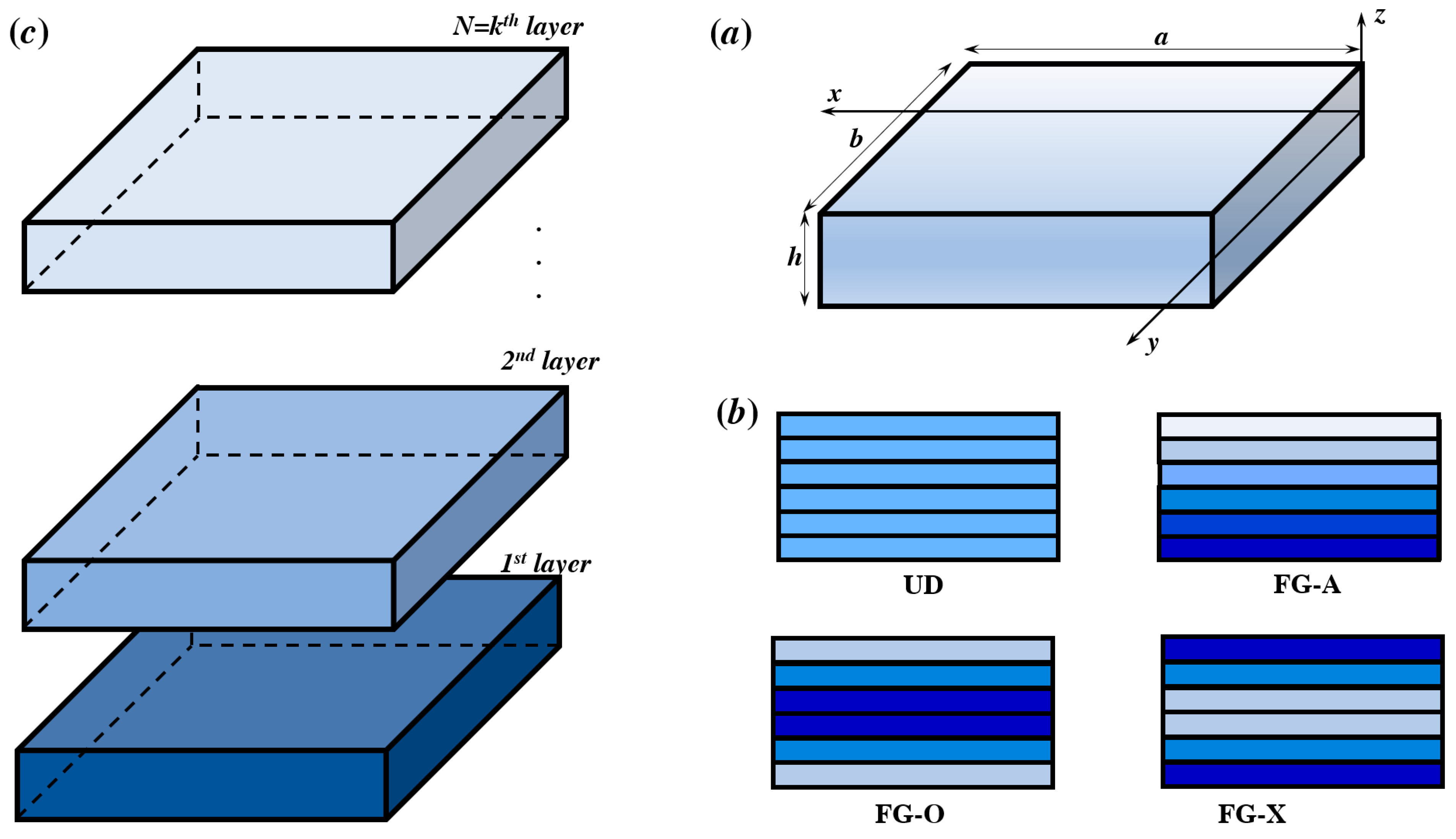
2. Mathematical Formulation of FG-GRNC Plate

2.1. Material Distribution and Graduation

Consider a multilayer plate of length a, width b and thickness h, as shown in Figure 1a. Each layer is made from an isotropic polymer matrix and reinforced by graphene nanoplatelets (GPLs), and all layers have the same thickness. The weight fraction of GPLs varies linearly along the thickness from layer to layer. In the present analysis, as shown in Figure 1b, four different patterns of GPL distribution are considered, the uniform distribution of GPLs along the nanoplate thickness (UD) and three FG distributions of GPLs (FG-X GRNC, FG-O GRNC and FG-A GRNC). The FG-X GRNC plates have the maximum weight fraction on the bottom and the top layers and minimum one at the middle of the nanoplate. The FG-O GRNC plates have the opposite GPLs weight fraction toward the FG-X GRNC plates. The GPL weight fraction in the FG-A GRNC plates gradually increases from the top layer to the bottom layer.
The weight fraction of GPLs g GPL ( k ) of kth layer (k = 1, 2, …, NL) for various patterns, are expressed as follows [17]:
{ U D :   g GPL ( k ) = g GPL * F G O :   g GPL ( k ) = g GPL * [ 4 N L + 2 ( N L + 1 2 | k N L + 1 2 | ) ] F G X :   g GPL ( k ) = g GPL * [ 4 N L + 2 ( 1 2 + | k N L + 1 2 | ) ] F G A :   g GPL ( k ) = g GPL * [ 2 k N L + 1 ]
where N L is the number of layers (Figure 1c) and g GPL * is the total GPLs weight fraction.
Using the Halpin–Tsai model, the effective Young’s modulus of kth layer of the nanoplate is stated as [65]:
E e ( k ) = 3 8 1 + ξ L η L V GPL ( k ) 1 η L V GPL ( k ) E m + 5 8 1 + ξ W η W V GPL ( k ) 1 η W V GPL ( k ) E m
where
η L = ( E GPL / E m ) 1 ( E GPL / E m ) + ξ L
η W = ( E GPL / E m ) 1 ( E GPL / E m ) + ξ W
ξ L = 2 ( a GPL h GPL )
ξ W = 2 ( w GPL h GPL )
E m and E GPL are Young’s modulus of polymer matrix and the GPLs reinforcement, respectively. The effective Poisson’s ratio υ e ( k ) and mass density ρ e ( k ) of kth layer of the nanocomposite plate are computed using the rule of mixture and are expressed as follows:
υ e ( k ) = υ GPL V GPL ( k ) + υ m V m
ρ e ( k ) = ρ GPL V GPL ( k ) + ρ m V m
υ GPL and υ m are Poisson’s ratio of the GPLs reinforcement and the epoxy matrix. V GPL ( k ) is the GPLs volume fraction of kth layer, and V m = 1 V GPL ( k ) is related to the matrix.
V GPL ( k ) = g GPL ( k ) g GPL ( k ) + ( ρ GPL / ρ m ) ( 1 g GPL ( k ) )

2.2. Basic Equations

To describe the field of displacement, a novel hyperbolic shear theory is proposed which contains the classical, first or higher-order plate terms as follows
u ( x , y , z ) = u 0 z w 0 x + Φ ( z ) ψ x v ( x , y , z ) = v 0 z w 0 y + Φ ( z ) ψ y w ( x , y , z ) = w 0 + Φ ( z ) ψ z  
in which u , v and w are the displacements along x , y and z directions, respectively. u 0 , v 0 and w 0 are the horizontal and the vertical displacements at the midplane of the plate. ψ x and ψ y are the rotation of the transverse normals around the 𝑥 and 𝑦 axes, respectively. Φ ( z ) is a shape function for the shear distribution. Four functions presented in Table 1 are selected to evaluate the accuracy and reliability of the present analysis. The variation of the used shape functions through the thickness direction is illustrated in Figure 2.
The strain fields of the nanocomposite plate have the following form:
{ ε x x ε y y ε z z γ x y γ y z γ x z } = [ ε x x ( 0 ) ε x x ( 1 ) ε x x ( 2 ) 0 0 ε y y ( 0 ) ε y y ( 1 ) ε y y ( 2 ) 0 0 0 0 0 0 ε z z 0 γ x y ( 0 ) γ x y ( 1 ) γ x y ( 2 ) 0 0 0 0 0 γ y z 0 0 0 0 0 γ x z 0 0 ] { 1 z Φ ( z ) Φ ( z ) Φ ( z ) }
where the primary strains ε i j ( 0 ) and γ i j ( 0 ) can be written as functions in terms of derivative of displacement field as
{ ε x x ( 0 ) ε y y ( 0 ) γ x y ( 0 ) } = { u 0 x v 0 y v 0 x + u 0 y } ,   { ε x x ( 1 ) ε y y ( 1 ) γ x y ( 1 ) } = { 2 w 0 x 2 2 w 0 y 2 2 2 w 0 x y } , { ε x x ( 2 ) ε y y ( 2 ) γ x y ( 2 ) } = { ψ x x ψ y y ψ y x + ψ x y } ,   { γ x z ( 0 ) γ y z ( 0 ) } = { ψ x + ψ z x ψ y + ψ z y } ,   ε z z ( 0 ) = ψ z

2.3. Nonlocal Strain Gradient Elasticity Theory

By including the coupling physical impact of the strain gradient stress and nonlocal elastic stress fields, Lim et al. [70] proposed a function of stresses as
σ i j = σ i j ( 0 ) d σ i j ( 1 ) d x
Here, σ i j ( 0 ) is the classical stress corresponds to strain ε k l and the higher-order stress σ i j ( 1 ) corresponds to strain gradient ε k l , x , and they are given by the following form [70]:
σ i j ( 0 ) = 0 L C i j k l α 0 ( x , x , e 0 a ) ε k l , x ( x ) d x
σ i j ( 1 ) = l 2 0 L C i j k l α 1 ( x , x , e 1 a ) ε k l , x ( x ) d x
where C i j k l represent the fourth-order elastic coefficients and l (nm) is defined as the material length scale parameter presented to reflect the significance of the strain gradient stress field. e 0 a and e 1 a (nm) are the nonlocal parameters presented to reflect the significance of the nonlocal elastic stress field. α 0 ( x , x , e 0 a ) and α 1 ( x , x , e 1 a ) are the nonlocal attenuation functions developed by Eringen [29]. Applying the linear differential operators
i = 1 ( e a ) 2 2
for e = e 0 = e 1 on both sides of Equation (13) and rearranging the expression yield
[ 1 ( e 1 a ) 2 2 ] [ 1 ( e 0 a ) 2 2 ] σ i j = C i j k l [ 1 ( e 1 a ) 2 2 ] ε k l C i j k l l 2 [ 1 ( e 0 a ) 2 2 ] 2 ε k l
where 2 represents the Laplacian operator. The total nonlocal strain gradient constitutive relations can be expressed as, Daikh et al. [39]
[ 1 μ 2 ] σ i j = C i j k l [ 1 λ 2 ] ε k l
where μ = ( e a ) 2 and λ = l 2 .
Using the generalized quasi-3D shear deformation theory, the nonlocal strain gradient constitutive stress–strain relations are governed by
[ 1 μ 2 ] { σ x x σ y y σ z z τ y z τ x z τ x y } ( k ) = [ 1 λ 2 ] [ Q 11 Q 12 Q 13 Q 12 Q 22 Q 23 Q 13 0 0 0 Q 23 0 0 0 Q 33 0 0 0 0 0 0 Q 44 0 0 0 0 0 0 0 0 0 0 Q 55 0 0 Q 66 ] ( k ) { ε x x ε y y ε z z γ y z γ x z γ x y }
As the normal strain in z-direction can be discarded (non-stretching), ε z z ( 0 ) = 0 , and hence
Q 11 ( k ) = Q 22 ( k ) = E e ( k ) 1 υ e ( k ) 2 Q 12 ( k ) = υ e ( k ) Q 11 ( k ) Q 44 ( k ) = Q 55 ( n ) = Q 66 ( k ) = E e ( k ) 2 ( 1 + υ e ( k ) )
However, to include the stretching through thickness, the normal strain ε z z ( 0 ) 0 , then Q i j are the 3D elastic constants:
Q 11 ( k ) = Q 22 ( k ) = Q 33 ( k ) = ( 1 υ e ( k ) ) υ e ( k ) λ ( z ) Q 12 ( k ) = Q 13 ( k ) = Q 23 ( k ) = λ ( z ) Q 44 ( k ) = Q 55 ( k ) = Q 66 ( k ) = μ ( z )
where ( z ) = υ e ( k ) E e ( k ) ( 1 2 υ e ( k ) ) ( 1 + υ e ( k ) ) and μ ( z ) = E e ( k ) 2 ( 1 + υ e ( k ) ) are the Lamé’s coefficients.

2.4. Equilibrium Equations

The variational principle is utilized to obtain the equilibrium equations of the GRNC plates which state that
δ ( U V ) = 0
where U and V are the strain energy and potential energy of the applied loads, respectively. The total strain energy of the FG-GRNC laminated plate can be expressed as
δ U = V σ i j   δ ε i j d V  
The variation of the potential energy of the applied loads can be given as
δ V = A q δ w d A + A [ N ¯ x x 0 w 0 x δ w 0 x + N ¯ y y 0 w 0 y δ w 0 y ] d A
Here, q presents the external transverse applied load. N ¯ x x 0 and N ¯ y y 0 are the in-plane applied loads in x-direction and y-direction, respectively.
The force and moment resultants may be portrayed by
{ N i j , M i j , S i j } = h / 2 h / 2 { 1 , z , Φ ( z ) } σ i j dz ,   i , j = x , y R i z = h / 2 h / 2 Φ ( z ) σ i z dz Q z z = h / 2 h / 2 Φ ( z ) σ z z dz
Substituting Equations (12) and (19) into the variational form in Equation (22) yields
  Ω [ N x x δ u x + N y y δ v y + N x y ( δ u y + δ v x ) + Q z z δ ψ z M x x 2 δ w x 2 2 M x y 2 δ w x y + S x x δ ψ x x + S y y δ ψ y y + S x y ( δ ψ x y + δ ψ y x ) + R x z ( δ ψ x + δ ψ z x ) + R y z ( δ ψ y + δ ψ z y ) q δ w N ¯ x x 0 w 0 x δ w 0 x + N ¯ y y 0 w 0 y δ w 0 y
  Ω [ N x x δ u x + N y y δ v y + N x y ( δ u y + δ v x ) + Q z z δ ψ z M x x 2 δ w x 2 2 M x y 2 δ w x y + S x x δ ψ x x + S y y δ ψ y y + S x y ( δ ψ x y + δ ψ y x ) + R x z ( δ ψ x + δ ψ z x ) + R y z ( δ ψ y + δ ψ z y ) q δ w N ¯ x x 0 w 0 x δ w 0 x + N ¯ y y 0 w 0 y δ w 0 y ] = 0
Then, the equilibrium equation of the GRNC plate is derived as follows:
δ u :   N x x x + N x y y = 0 δ v :   N x y x + N y y y = 0 δ w :   2 M x x x 2 + 2 2 M x y x y + 2 M y y y 2 + q + N ¯ x x 0 2 w 0 x 2 + N ¯ y y 0 2 w 0 y 2 = 0 δ ψ x :   S x x x + S x y y R x z = 0 δ ψ y :   S x y x + S y y y R y z = 0 δ ψ z :   R x z x + R y z y Q z z = 0
Substituting Equation (24) into the constitutive stress–strain equation described by Equation (19) give
[ 1 μ 2 ] { N x x N y y N x y M x x M y y M x y S x x S y y S x y Q z z } = 1 λ 2 [ A 11 A 12 0 B 11 B 12 0 B 11 s B 12 s 0 G 13 s A 12 A 11 0 B 12 B 11 0 B 12 s B 11 s 0 G 13 s 0 0 A 66 0 0 B 66 0 0 B 66 s 0 0 0 A 66 0 0 B 66 0 0 B 66 s 0 B 12 B 11 0 D 12 D 11 0 D 12 s D 11 s 0 H 13 s 0 0 B 66 0 0 D 66 0 0 D 66 s 0 B 11 s B 12 s 0 D 11 s D 12 s 0 F 11 s F 12 s 0 J 13 s B 12 s B 11 s 0 D 12 s D 11 s 0 F 12 s F 11 s 0 J 13 s 0 0 B 66 s 0 0 D 66 s 0 0 F 66 s 0 G 13 s G 13 s 0 H 13 s H 13 s 0 J 13 s J 13 s 0 K 13 s ] u 0 x v 0 y u 0 y + v 0 x 2 w 0 x 2 2 w 0 y 2 2 2 w 0 x y ψ x x ψ y y ψ x y + ψ y x ψ z
[ 1 μ 2 ] { R x z , R y z } = [ 1 λ 2 ] A 44 s { ψ x + ψ z x , ψ y + ψ z y }
in which the composite stiffnesses can be expressed as
{ A 11 ,   B 11 ,   B 11 s ,   D 11 , D 11 s , F 11 s } = h / 2 h / 2 ( λ ( z ) + 2 μ ( z ) ) { 1 ,   z , Φ ( z ) , z 2 , z Φ ( z ) , ( Φ ( z ) ) 2 } d z { A 12 ,   B 12 ,   B 12 s ,   D 12 , D 12 s , F 12 s } = h / 2 h / 2 λ ( z ) { 1 ,   z , Φ ( z ) , z 2 , z Φ ( z ) , ( Φ ( z ) ) 2 } d z { A 66 ,   B 66 ,   B 66 s ,   D 66 , D 66 s , F 66 s } = h / 2 h / 2 μ ( z ) { 1 ,   z , Φ ( z ) , z 2 , z Φ ( z ) , ( Φ ( z ) ) 2 } d z A 44 s = h / 2 h / 2 μ ( z ) ( Φ ( z ) ) 2 d z K 33 s = h / 2 h / 2 ( λ ( z ) + 2 μ ( z ) ) ( Φ ( z ) ) 2 d z { G 13 s ,   H 13 s , J 13 s } = h / 2 h / 2 λ ( z ) { 1 ,   z , Φ ( z ) } Φ ( z ) d z
Therefore, the governing equilibrium equation of GRNC plates based on the nonlocal strain gradient theory can be stated as
( 1 λ 2 ) [ A 11 2 u 0 x 2 + A 66 2 u 0 y 2 + ( A 12 + A 66 ) 2 v 0 x y B 11 3 w 0 x 3 ( B 12 + 2 B 66 ) 3 w 0 x y 2 + B 11 s 2 ψ x x 2 + B 66 s 2 ψ x y 2 + ( B 12 s + B 66 s ) 2 ψ y x y + G 13 s ψ z x ] = 0
( 1 λ 2 ) [ ( A 12 + A 66 ) 2 u 0 x y + A 11 2 v 0 y 2 + A 66 2 v 0 x 2 ( B 12 + 2 B 66 ) 3 w 0 x 2 y B 11 3 w 0 y 3 + ( B 12 s + B 66 s ) 2 ψ x x y + B 11 s 2 ψ y y 2 + B 66 s 2 ψ y x 2 + G 13 s ψ z y ] = 0
( 1 λ 2 ) [ B 11 3 u 0 x 3 + ( B 12 + 2 B 66 ) 3 u 0 x y 2 + ( B 12 + 2 B 66 ) 3 v 0 x 2 y + B 11 3 v 0 y 3 D 11 4 w 0 x 4 ( 2 D 12 + 4 D 66 ) 4 w 0 x 2 y 2 D 11 4 w 0 y 4 + D 11 s 3 ψ x x 3 + ( D 12 s + 2 D 66 s ) 3 ψ x x y 2 + ( D 12 s + 2 D 66 s ) 3 ψ y x 2 y + D 11 s 3 ψ y y 3 + H 13 s ( 2 ψ z x 2 + 2 ψ z y 2 ) + ( 1 μ 2 ) [ q + N ¯ x x 0 2 w 0 x 2 + N ¯ y y 0 2 w 0 y 2 ] = 0 ]
( 1 λ 2 ) [ B 11 s 2 u 0 x 2 + B 66 s 2 u 0 y 2 + ( B 12 s + B 66 s ) 2 v 0 x y D 11 s 3 w 0 x 3 ( D 12 s + 2 D 66 s ) 3 w 0 x y 2 + F 11 s 2 ψ x x 2 + F 66 s 2 ψ x y 2 A 44 s ψ x + ( F 12 s + F 66 s ) 2 ψ y x y + ( J 13 s A 44 s ) ψ z x ] = 0
( 1 λ 2 ) [ ( B 12 s + B 66 s ) 2 u 0 x y + B 11 s 2 v 0 y 2 + B 66 s 2 v 0 x 2 ( D 12 s + 2 D 66 s ) 3 w 0 x 2 y D 11 s 3 w 0 y 3 + ( F 12 s + F 66 s ) 2 ψ x x y + F 11 s 2 ψ y y 2 + F 66 s 2 ψ y x 2 A 44 s ψ y + ( J 13 s A 44 s ) ψ z y ] = 0
( 1 λ 2 ) [ G 13 s u 0 x G 13 s v 0 y + H 13 s ( 2 w 0 x 2 + 2 w 0 y 2 ) ( J 13 s A 44 s ) ψ x x ( J 13 s A 44 s ) ψ y y + A 44 s ( 2 ψ z x 2 + 2 ψ z y 2 ) K 33 s ψ z ] = 0

3. Analytical Solution

Based on the five variable quasi-3D HSDT in conjunction with nonlocal strain gradient theory, an analytical solution is developed by employing the Galerkin approach considering various boundary conditions. Galerkin expressions of displacements can be stated as:
{ u 0 , ψ x } = m = 1 n = 1 { U m n , X m n } X m ( x ) x Y n ( y ) { v 0 , ψ y } = m = 1 n = 1 { V m n , Z m n } X m ( x ) Y n ( y ) y { w 0 , ψ z } = m = 1 n = 1 { W m n , Ψ m n } X m ( x ) Y n ( y )
where U m n , V m n , W m n , X m n , Z m n and Ψ m n are arbitrary parameters. m and n are mode numbers. The functions X m ( x ) and Y n ( y ) that satisfy the simply supported and clamped boundary conditions are expressed in Table 2 as follows:
By substituting Equation (34) in Equations (28)–(33), one obtains
[ K ] 6 × 6 { U m n V m n W m n X m n Z m n Ψ m n } = { 0 0 q 0 0 0 0 }
The elements K i j of the matrix [K] are expressed in detail in Appendix A
The applied load has a sinusoidal distribution, and can be written as [71],
q 0 = q 0 a 0 b sin 2 ( α x ) sin 2 ( β y ) d x d y

4. Numerical Results

The present nanocomposite plate is made of a mixture of epoxy as a matrix and GPLs as reinforcement. The plate is exposed to in-plane load in two directions ( N ¯ x x 0 = χ 1 N c r ,   N ¯ y y 0 = χ 2 N c r ) for buckling analysis, and transverse sinusoidal load for the bending analysis.
Young’s modulus, Poisons ratio and the mass density of the matrix (Epoxy) are given as E m = 3   Gpa , ν m = 0.34 and ρ m = 1200   kg / m 3 , whereas for the GPLs reinforcement, E GPL = 1010   Gpa , ν GPL = 0.186 and ρ GPL = 1060   kg / m 3 .
In this analysis, the thickness, length and width of the nanoplate are h = 20   nm , a = 200   nm and b = 200   nm , and it is made of GNLS with a length a GPL = 3   nm , thickness h GPL = 0.7   nm and width w GPL = 1.8   nm , [72]. The normalized critical buckling load, displacements and normalized stresses are evaluated with the following forms.
Dimensionless critical buckling load:
N ¯ = 10 2 N c r ( 1 v m ) E m h
Dimensionless axial and transverse displacements:
u ¯ = 10 h a 2 q 0 w ( 0 ,   b 2 , z ) w ¯ = 10 h a 2 q 0 w ( a 2 ,   b 2 , z )
Dimensionless stresses:
σ ¯ x x = h a q 0 σ x x ( a 2 ,   b 2 , h 2 ) σ ¯ z z = h a q 0 σ z z ( a 2 ,   b 2 , h 2 ) τ ¯ x z = h a q 0 τ x z ( 0 ,   b 2 , 0 ) τ ¯ x y = h a q 0 τ x y ( 0 ,   0 , z )

4.1. Verification Analysis

To check the correctness and accuracy of the proposed method of solution and our shape function, a comparative evaluation between the obtained results and some valid predictions from the literature is carried out. The validation of the current model with those obtained by Wu et al. [73], Gholami and Ansari [74] and Thai et al. [18] are presented in Table 3. This analysis is related to the buckling of functionally graded graphene reinforced composite square plates with thickness h = 0.045   m and length a = 0.45   m .
On the other hand, more validations are made in Table 4 which summarizes the transverse displacement, axial stresses and shear stresses of an FG plate with volume fraction index p = 0 (fully ceramic). Young’s modulus of the ceramic constituent (Zirconia ZrO2) is E c = 151   GPa , while Poisson’s ratio ν c = 0.3 . The stretching effect is considered in these results. Zenkour [76] used the sinusoidal shear deformation theory as shape function and Navier procedure to solve the equilibrium equations. The same procedure is used by Bessaim et al. [77] using the hyperbolic theory. Neves et al. [78] applied Carrera’s Unified Formulation and Murakami’s Zig-Zag theory for the analysis.
From the above results, it can be concluded that the proposed solutions for buckling or bending are in good agreement with the other results.

4.2. Parametric Study

4.2.1. Buckling Analysis

In this section, the effect of weight fraction of the constituents on the buckling behavior of the GRNC plates will be analyzed and investigated. Firstly, the effect of weight fraction g GPL * and various distributions of GPLs on the critical buckling load with and without stretching effect will be presented.
Firstly, in Table 5, the effect of g GPL * constituent and the reinforcement distribution on dimensionless buckling load of simply supported plates subjected to uniaxial compressive in-plane loads ( χ 1 = 1 .   χ 2 = 0 ) is tabulated using various HSDTs. For this the critical buckling load increases. The FG-O GRCL plates have the lowest critical buckling load while the highest values are for the FG-X GRCL plates. The thickness stretching has an important effect on the response of the GRNC plate, especially for plates with 1 %   of GPLs.
Table 6 illustrates the impact of in-plane charges (uniaxial and biaxial) on the critical buckling load of 1% of GPLs plates. It is clear that the obtained values for fully clamped plates (CCCC) are higher than the other plates; however, the lowest loads are for the simply supported plates (SSSS). Additionally, the difference between quasi-3D theories ( ε z z 0 ) and classical shear deformation theories ( ε z z = 0 ) is significant for the fully clamped plates.
To capture the size-dependent effects, Table 7 summarizes the dimensionless critical buckling load of various patterns of reinforcement under the impact of length scale and nonlocal parameters. The results are reported here for the only weight fraction g GPL * = 1 % . As it is reasonable to expect, the buckling response is affected by the nonlocal parameter, with a clear decrease in the stiffness and critical buckling load for an increasing nonlocal parameter μ. Unlike the nonlocality effect, the increase in the length scale parameter leads to an increment in the critical buckling load wherever the GPLs distribution patterns is.
The influence of the number of layers N L , length-to-thickness ratio and aspect ratio on buckling response of simply supported GRNC plates subjected to biaxial in-plane compressive loads is presented in Table 8. The results are focused on the only FG-O distribution of GPLs with weight fraction g GPL * = 1 % . It can be observed that the increase in the number of layers decreases the buckling load FG-O GRNC plates. In addition, the increase in the length-to-thickness ratio and aspect ratio leads to a decrement in the dimensional buckling load.
The size-dependent influence on the critical buckling load of GRNC plates is controlled by including the nonlocal parameter  μ and the length-scale parameter λ (see Appendix A). The results of the size effect are plotted in Figure 3. From the figure, the increase in the parameter μ reduces the stiffness of the GRNC plate and therefore leads to a decrement in the critical buckling load. Otherwise, unlike the nonlocality effect, the critical buckling load is increased by increasing the length-scale parameter λ .
Dimensionless critical buckling load in terms of the number of layers for various GPLs reinforcement patterns is presented in Figure 4. The weight fraction is taken as g GPL * = 1 % . Similar results are obtained for the patterns FG-A and UD where the number of layers does not change the results. For the FG-O pattern, the critical buckling load decreases by increasing the total number of layers. In contrast, the increase in the total number of layers decreases the buckling load, then tends to be constant for N     10 .
Variation of the critical buckling load of GRNC plates for different values of the length-to-width ratio of GPL nanofillers is presented in Figure 5. The four GPLs reinforcement patterns are analyzed. It can be seen that the increase in the thickness-to-length ratio a GPL / h GPL leads to an increment in critical buckling load.
To better comprehend the effect of GPLs geometry, Figure 6 depicts the critical buckling load versus the width-to-length ratio b GPL / a GPL . The plotted results show that the width-to-length ratio has a significant effect on the critical buckling load for values less than 15 , where critical buckling load increase. The results are almost constant for greater values of ratio (≥15) regardless GPLs reinforcement pattern.
Figure 7 plots the critical buckling loads of GRNC plates versus the aspect ratio b / a subjected to compressive biaxial in-plane loads. The coefficient of the in-plane load in x-direction is assumed constant ( χ 1 = 1 ) , while the compressive loads in y-direction vary from 0 to 3. Except the case of χ 2 = 0 , dimensionless critical buckling load increases as aspect ratio increases. In addition, the intensity of in-plane loads has an important impact on critical buckling load where increasing compressive in-plane loads lead to a decrement in buckling loads.
Figure 8 illustrates the influence of weight faction variation on dimensionless critical buckling load of GRNC plates under various boundary conditions and for various GPLs reinforcement patterns. The dimensionless critical buckling loads increase linearly by increasing a weight fraction g GPL * for all boundary conditions and reinforcement patterns.

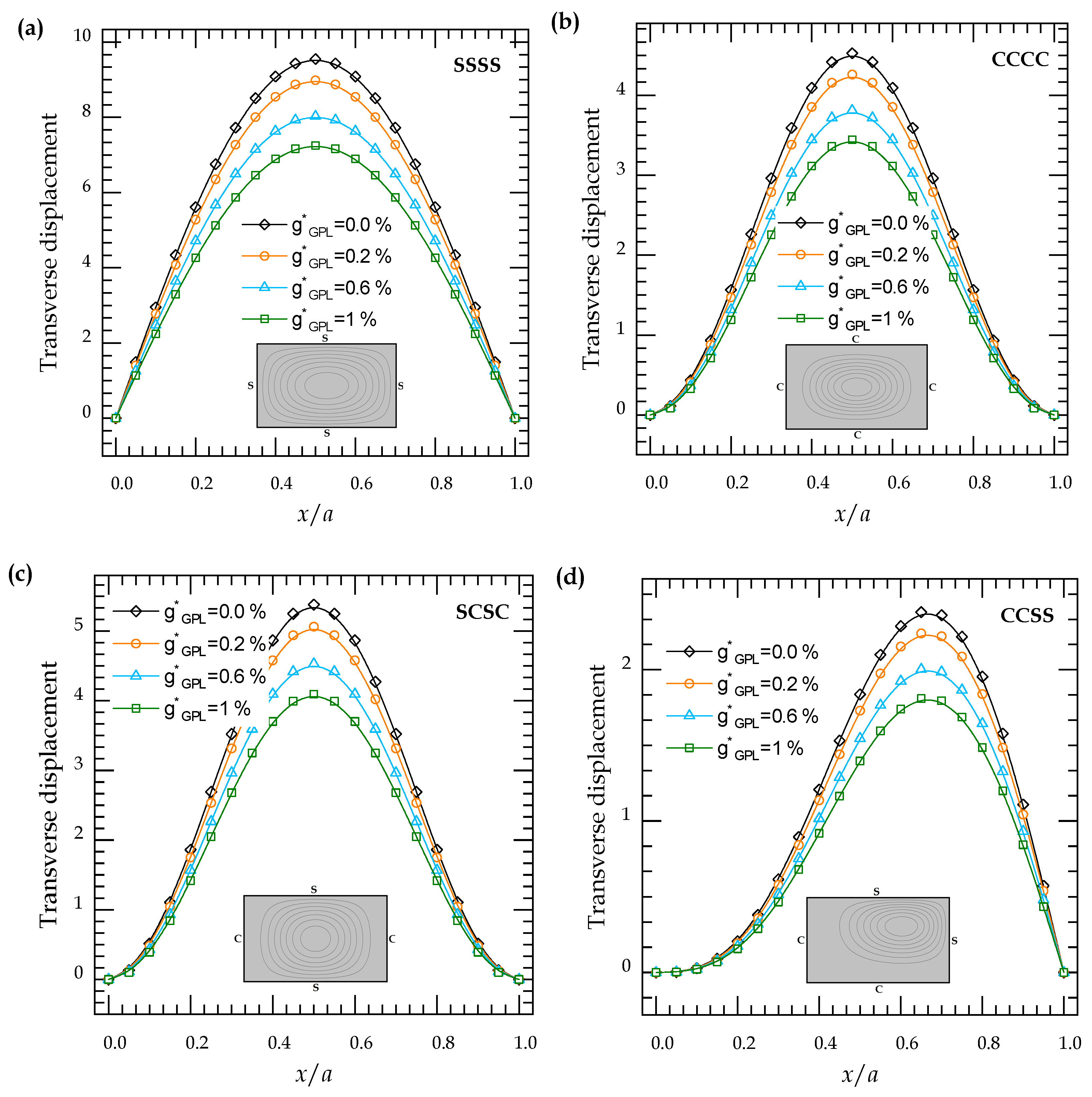
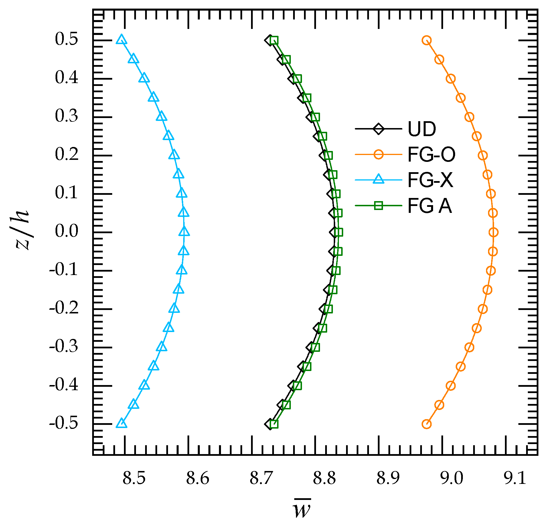
4.2.2. Bending Analysis

In this section, using various HSDTs, comprehensive analysis of displacements and stresses in multilayer FGNC plates are carried out. Table 9 shows the influence of thickness stretching on longitudinal displacement u ¯ , transverse displacement w ¯ and the stresses σ ¯ x x , σ ¯ x y and σ ¯ x z of square simply supported FGNC laminated plate with various patterns of reinforcement. Similar results are obtained by comparing our hyperbolic theory with the sinusoidal theory. It can be observed that the thickness stretching have a significant impact on the displacements of the plate. In addition, it can be seen that the difference between displacements u ¯ with and without the thickness stretching effect is very large for FG-A GRNC laminated plates.
In Table 10, the effect of g GPL * constituent and different reinforcements distribution on the dimensionless central deflection of GRNC plates subjected to various boundary conditions is tabulated using the present theory. The increase in the g GPL * reinforced percentage tends to decrease the transverse displacements. The FG-O GRCL plates have the highest central deflections while the lowest values are for the FG-X GRCL plates. The thickness stretching has an important effect on the response of the GRNC plate, especially for the fully clamped plates (CCCC).
Table 11 shows the size-dependent effects on the dimensionless central of GRNC plates with various patterns of reinforcement where the impact of length scale and nonlocal parameters is studied. The results are here reported for the only weight fraction g GPL * = 1 % . From this table, the static bending response is affected by the nonlocal parameter, increasing nonlocal parameter μ leads to a decrement in plate stiffness and subsequently an increment in transverse displacement. Unlike the nonlocality effect, the increase in the length scale parameter leads to a decrement in transverse displacement wherever the GPLs distribution patterns remain constant.
In Figure 9, dimensionless central deflection versus the total number of layers for various GPL reinforcement patterns is depicted for weight fraction g GPL * = 1 % . Unlike the previous results of buckling response obtained in Figure 9, the dimensionless central deflection increases by increasing the total number of layers for FG-O pattern and decreases for the FG-X pattern.
In Figure 10, the impact of nonlocal and small-scale parameters on the central deflection of simply supported GRNC plates for various GPLs reinforcement patterns is investigated. As we demonstrated in the buckling analysis, the inclusion of nonlocal parameter μ reduces the plate stiffness, so, transverse displacement increases. In addition, the increase in small-scale parameter λ leads to a decrement in transverse displacement.
In Figure 11, dimensionless central deflection versus the length-to-thickness ratio of the GPLs nanofillers using various GPLs reinforcement patterns is demonstrated. It is clear that the increase in the thickness-to-length ratio a GPL / h GPL leads to a decrement in dimensionless central deflection.
Figure 12 depicts the dimensionless central deflection influenced by width-to-length ratio b GPL / a GPL . It can be observed that the width-to-length ratio has a significant effect on the dimensionless central deflection for values less than 15 , where central deflection decreases. The results are almost constant for greater values of ratio (≥15) regardless of the GPL reinforcement pattern.
Figure 13 plots the influence of weight fraction g GPL * on the transverse displacement of GRNC plates subjected to various boundary conditions. The highest deflections are for SSSS plates and pure Epoxy ( g GPL * = 0.0 % ) .
Figure 14 shows the variation of the in-plane displacement through-the-thickness of various types of GPLs reinforcements. The plate is assumed simply supported. In the upper-half plate, the in-plane displacements of the FG-O GRNC plates are found to be of the smallest magnitudes and that of the FG-A GRNC plates, of the largest magnitudes. However, in the lower-half plate, the in-plane displacements of the FG-A GRNC plates are found to be of the smallest magnitudes.
In Figure 15, dimensionless transverse displacement w ¯ through-the-thickness of the GRNC plate with simply supported boundary conditions for various GPLs reinforcement patterns is investigated. It can be observed that the maximum transverse displacement occurs at a point on the mid-plane of the GRNC plate and their magnitudes for the FG-O pattern are larger than that for the other patterns. Therefore, in order to make the most decrease in the dimensionless transverse displacement w ¯ , it is better to put the GNLs nanofiller as far as away from the middle axis of the GRNC plate which creates more flexural rigidity.
Figure 16 contains the plots of dimensionless transverse displacement of GRNC plate with uniformly distributed GPLs by considering the weight fraction impact. The maximum values of the dimensionless transverse displacement are for the pure Epoxy plate ( g GPL * = 1 % ) , whereas the minimum values are for plate with weight fractions g GPL * = 1 % .
Dimensionless stresses for different types of the GRNC plate are plotted in Figure 17. It can be found that the stresses σ ¯ x x and σ ¯ z z are tensile at the top surface and compressive at the bottom surface, unlike the σ ¯ x y stresses. For the UD, FG-O and FG-X patterns, the stresses, σ ¯ x x , σ ¯ x y and σ ¯ z z are null at the mid-plane of the plate because of the symmetric distribution of the GPLs nanofillers. For the plates with a symmetric distribution of the GPLs, FG-O and UD patterns, the maximum shear stresses τ ¯ x z occur at a point on the mid-plane of the GRNC plate. For the FG-X GRNC plate, considerable reduction of stresses τ ¯ x z at the mid-plane of the plate due to the absence of GPLs nanofillers at the central layers.

5. Conclusions

Novel quasi-3D hyperbolic higher order shear deformation theory in conjunction with modified continuum nonlocal strain gradient theory is used for bending and buckling analyzes of FG GRNC plates. The governing equations are derived by applying Hamilton’s principle and solved analytically using the proposed Galerkin method. The effective Young’s modulus of the GRNC plate was estimated using the Halpin–Tsai model, and Poisson’s ratio and mass density are computed by using the rule of mixture. Four different patterns of GPL distribution are considered in this study. The feasibility of the proposed solutions is effectuated by comparing them with the existing analytical solutions. The numerical examples show that:
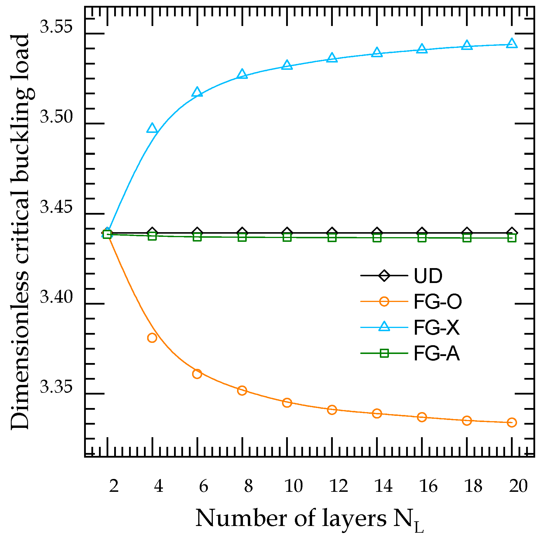
  • Unlike the FG-X GRNC plates, the increase in the number of layers leads to an improvement in the FG-X GRNC plate stiffness; therefore, the critical buckling load increases and the central deflection decreases.
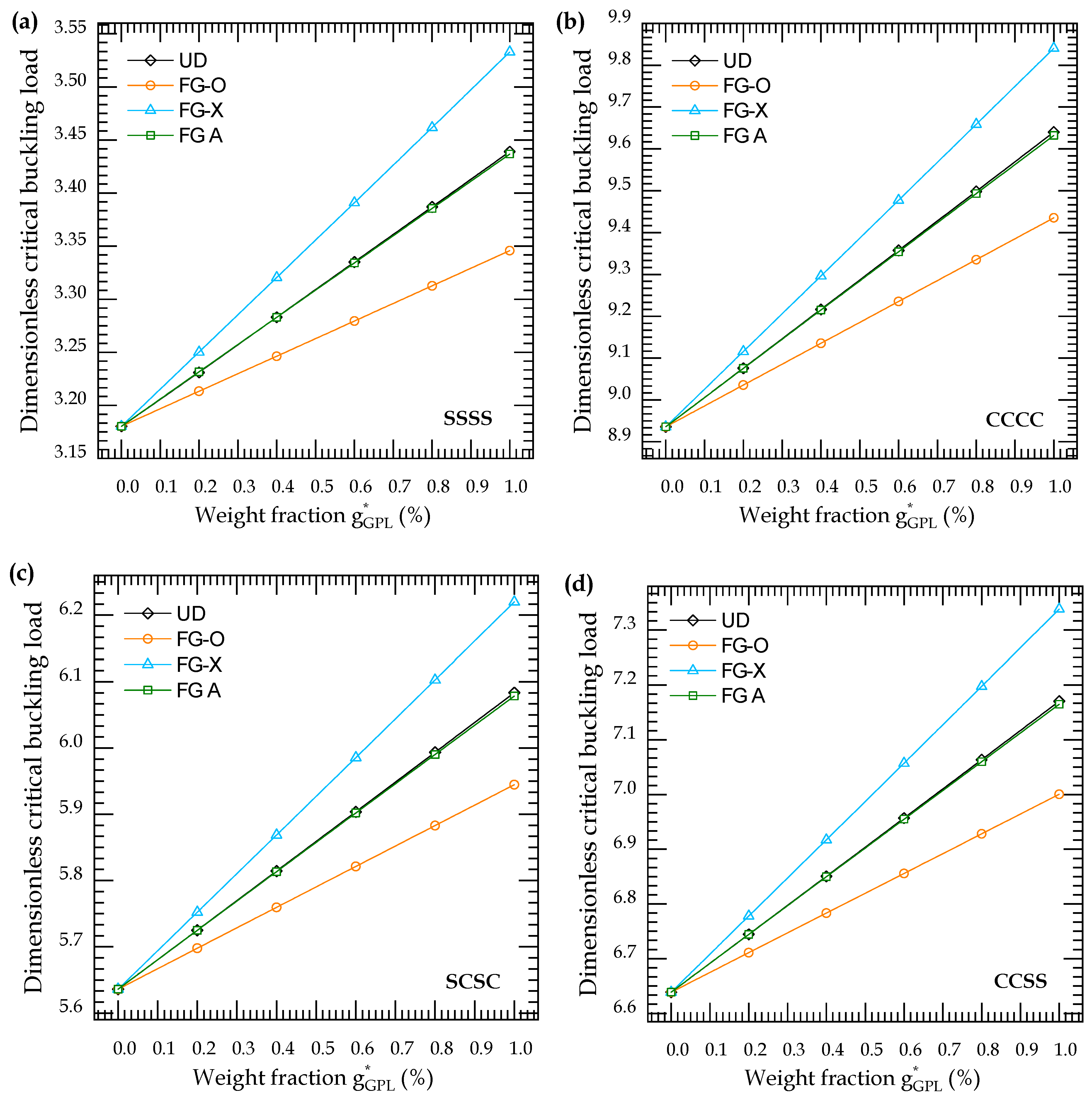
  • Both increasing the weight fraction and the number of layers can improve the stiffness of the GRNC plates.
  • The inclusion of thickness stretching has a significant effect on the response of the GRNC plate, especially for the fully clamped plate.
  • The inclusion of a nonlocal parameter leads to a decrease in buckling loads and an increase in transverse displacements, while the opposite is found when increasing the length-scale parameter.
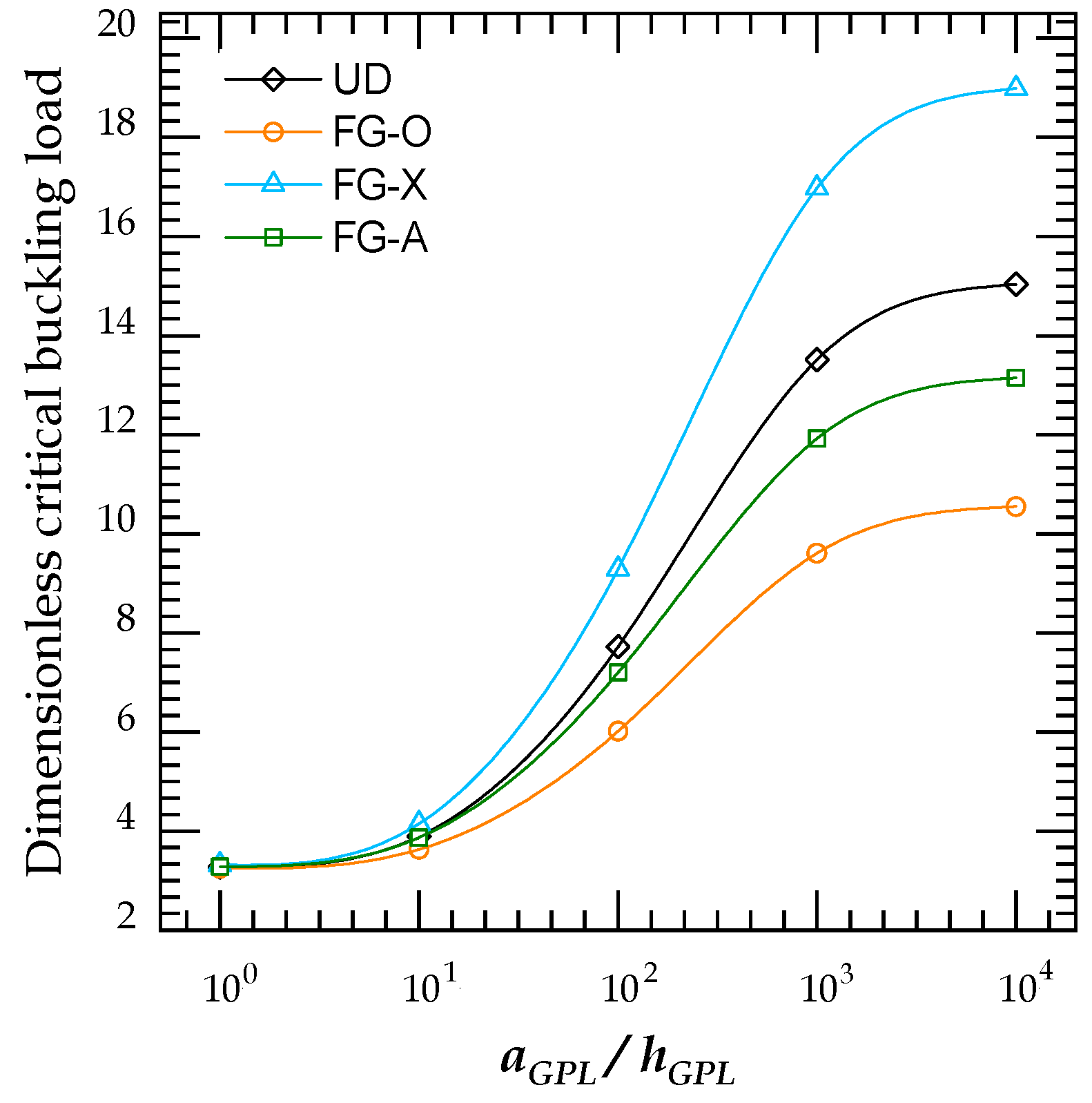
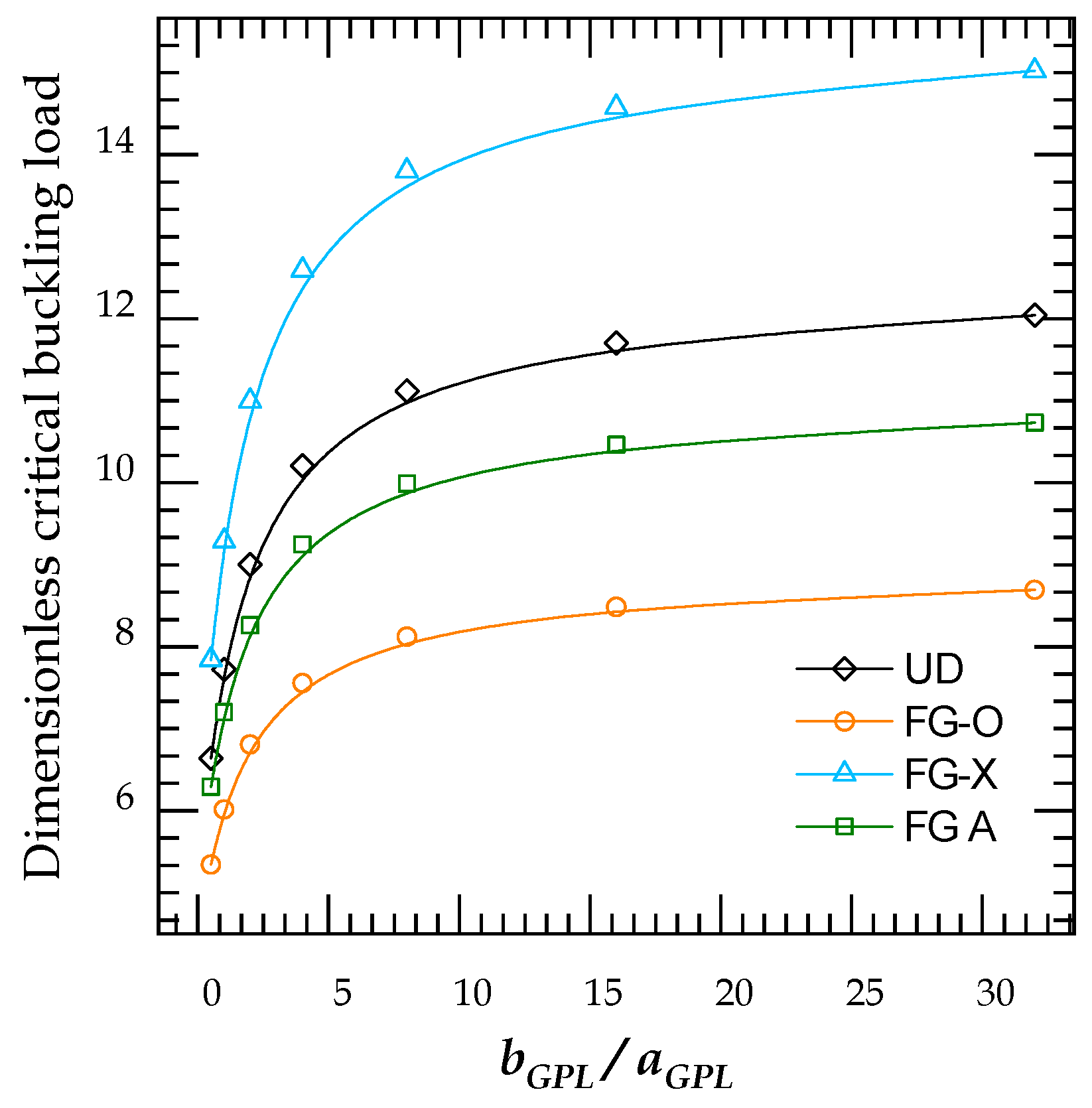
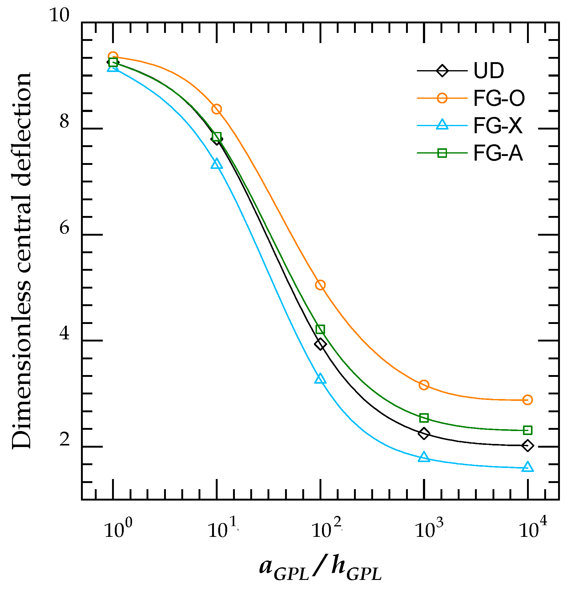
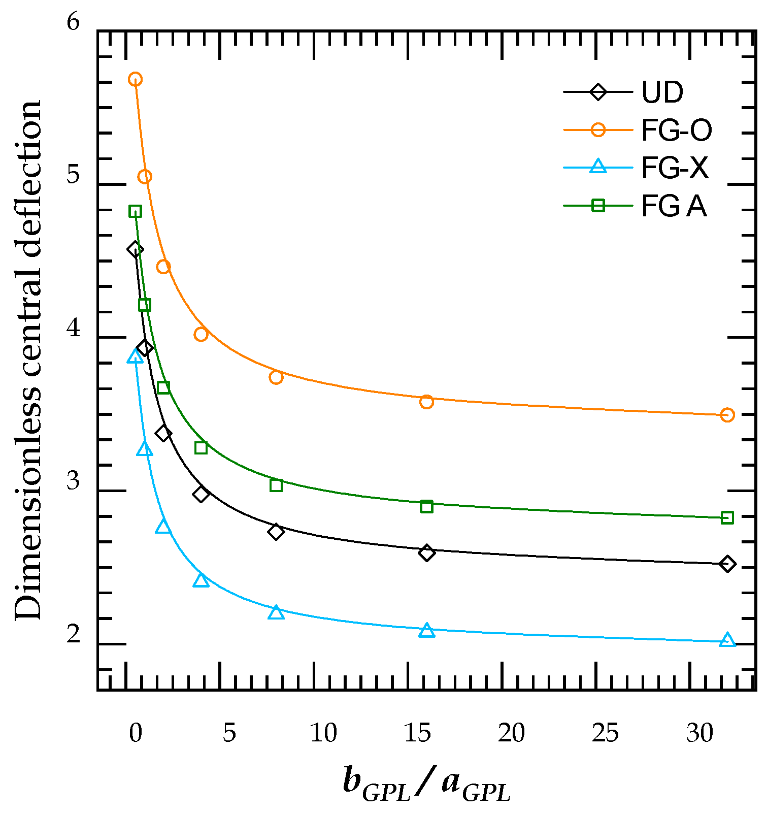
  • The FG-X reinforcement pattern has the better response under in-plane and transverse loadings, among the other analyzed distributions, due to their higher stiffness.
  • Increasing the length-to-width and length-to-thickness ratios result in increasing the total stiffness of the GRNC plate and consequently lead to higher critical buckling loads and lower transverse displacements.
This work plays a significant role in further studies in composite plates using the 3D elasticity model.

Author Contributions

Conceptualization, E.E.G., A.A.D. and M.A.E.; methodology, E.E.G., O.A.F. and A.M.A.; software, A.A.D. and M.A.E.; validation, E.E.G., O.A.F. and A.M.A.; formal analysis, A.A.D. and M.A.E.; investigation, E.E.G., A.A.D. and M.A.E.; resources, E.E.G., O.A.F. and A.M.A.; data curation, E.E.G., O.A.F. and A.M.A.; writing—original draft preparation, A.A.D. and O.A.F.; writing—review and editing, M.A.E.; visualization, E.E.G., A.A.D. and A.M.A.; project administration, M.A.E.; funding acquisition, E.E.G. All authors have read and agreed to the published version of the manuscript.

Funding

This research work was funded by Institutional Fund Projects under grant no. (IFPHI-254-135-2020). Therefore, authors gratefully acknowledge the technical and financial support from the Ministry of Education and King Abdulaziz University, DSR, Jeddah, Saudi Arabia.

Institutional Review Board Statement

Not applicable.

Informed Consent Statement

Not applicable.

Data Availability Statement

Not applicable.

Acknowledgments

This research work was funded by Institutional Fund Projects under grant no. (IFPHI-254-135-2020). Therefore, authors gratefully acknowledge the technical and financial support from the Ministry of Education and King Abdulaziz University, DSR, Jeddah, Saudi Arabia.

Conflicts of Interest

The authors declare no conflict of interest.

Appendix A

K 11 = A 11 0 a 0 b 3 X m x 3 Y n X m x Y n d x d y + A 66 0 a 0 b X m x 2 Y n y 2 X m x Y n d x d y λ [ ( A 11 + A 66 ) 0 a 0 b 3 X m x 3 2 Y n y 2 X m x Y n d x d y + A 11 0 a 0 b 5 X m x 5 Y n X m x Y n d x d y + A 66 0 a 0 b X m x 4 Y n y 4 X m x Y n d x d y ]
K 12 = ( A 12 + A 66 ) ( 0 a 0 b X m x 2 Y n y 2 X m x Y n d x d y λ [ 0 a 0 b 3 X m x 3 2 Y n y 2 X m x Y n d x d y + 0 a 0 b X m x 4 Y n y 4 X m x Y n d x d y ] )
K 13 = B 11 0 a 0 b 3 X m x 3 Y n X m x Y n d x d y ( B 12 + 2 B 66 ) 0 a 0 b X m x 2 Y n y 2 X m x Y n d x d y
λ [ ( B 12 + 2 B 66 + B 11 ) 0 a 0 b 3 X m x 3 2 Y n y 2 X m x Y n d x d y B 11 0 a 0 b 5 X m x 5 Y n X m x Y n d x d y ]
K 14 = B 11 s 0 a 0 b 3 X m x 3 Y n X m x Y n d x d y + B 66 s 0 a 0 b X m x 2 Y n y 2 X m x Y n d x d y λ [ ( B 11 s + B 66 s ) 0 a 0 b 3 X m x 3 2 Y n y 2 X m x Y n d x d y + B 11 s 0 a 0 b 5 X m x 5 Y n X m x Y n d x d y + B 66 s 0 a 0 b X m x 4 Y n y 4 X m x Y n d x d y ]
K 15 = ( B 12 s + B 66 s ) ( 0 a 0 b X m x 2 Y n y 2 X m x Y n d x d y λ [ 0 a 0 b 3 X m x 3 2 Y n y 2 X m x Y n d x d y + 0 a 0 b X m x 4 Y n y 4 X m x Y n d x d y ] )
K 16 = G 13 s ( 0 a 0 b X m x Y n X m x Y n d x d y λ [ 0 a 0 b 3 X m x 3 Y n X m x Y n d x d y + 0 a 0 b X m x 2 Y n y 2 X m x Y n d x d y ] )
K 21 = ( A 12 + A 66 ) ( 0 a 0 b 2 X m x 1 Y n y X m Y n y d x d y λ [ 0 a 0 b 4 X m x 4 Y n y X m Y n y d x d y + 0 a 0 b 2 X m x 2 3 Y n y 3 X m Y n y d x d y ] )
K 22 = A 11 0 a 0 b X m 3 Y n y 3 X m Y n y d x d y + A 66 0 a 0 b 0 b 2 X m x 2 Y n y X m Y n y d x d y λ [ ( A 11 + A 66 ) 0 a 0 b 2 X m x 2 3 Y n y 3 X m Y n y d x d y + A 11 0 a 0 b X m 5 Y n y 5 X m Y n y d x d y + A 66 0 a 4 X m x 4 Y n y X m Y n y d x d y ]
K 24 = ( B 12 s + B 66 s ) ( 0 a 0 b 2 X m x 2 Y n y X m Y n y d x d y λ [ 0 a 0 b 4 X m x 4 Y n y X m Y n y d x d y + 0 a 0 b 2 X m x 2 3 Y n y 3 X m Y n y d x d y ] )
K 25 = B 11 s 0 a 0 b X m 3 Y n y 3 X m Y n y d x d y + B 66 s 0 a 0 b 2 X m x 2 Y n y X m Y n y d x d y λ [ ( B 11 s + B 66 s ) 0 a 0 b 2 X m x 2 3 Y n y 3 X m Y n y d x d y + B 66 s 0 a 0 b 4 X m x 4 Y n y X m Y n y d x d y + B 11 s 0 a 0 b X m 5 Y n y 5 X m Y n y d x d y ]
K 26 = G 13 s ( 0 a 0 b X m Y n y X m Y n y d x d y λ [ 0 a 0 b 2 X m x 2 Y n y X m Y n y d x d y + 0 a 0 b X m 3 Y n y 3 X m Y n y d x d y ] )
K 13 = B 11 0 a 0 b 4 X n x 4 Y n X m Y n d x d y + ( B 12 + 2 B 66 ) 0 a 0 b 2 X m x 2 2 Y n y 2 X m Y n d x d y λ [ B 11 0 a 0 b 6 X n x 6 Y n X m Y n d x d y + ( B 11 + B 12 + 2 B 66 ) 0 a 0 b 4 X m x 4 2 Y n y 2 X m Y n d x d y + ( B 12 + 2 B 66 ) 0 a 0 b 2 X m x 2 4 Y n y 4 X m Y n d x d y ]
K 23 = B 11 0 a 0 b X m 4 Y n y 4 X m Y n d x d y + ( B 12 + 2 B 66 ) 0 a 0 b 2 X m x 2 2 Y n y 2 X m Y n d x d y λ [ ( B 11 + B 12 + 2 B 66 ) 0 a 0 b 2 X m x 2 4 Y n y 4 X m Y n d x d y + ( B 12 + 2 B 66 ) 0 a 0 b 4 X m x 4 2 Y n y 2 X m Y n d x d y + B 11 0 a 0 b X m 6 Y n y 6 X m Y n d x d y ]
K 33 = D 11 ( 0 a 0 b X m 4 Y n y 4 X m Y n d x d y + 0 a 0 b 4 X m x 4 Y n X m Y n d x d y ) 2 ( D 12 + 2 D 66 ) 0 a 0 b 2 X m x 2 2 Y n y 2 X m Y n d x d y λ [ D 11 ( 0 a 0 b 2 X m x 2 4 Y n y 4 X m Y n d x d y + 0 a 0 b 6 X m x 6 Y n X m Y n d x d y ) ] 2 ( D 12 + 2 D 66 ) 0 a 0 b 4 X m x 4 2 Y n y 2 X m Y n d x d y D 11 ( 0 a 0 b X m 6 Y n y 6 X m Y n d x d y + 0 a 0 b 4 X m x 4 2 Y n y 2 X m Y n d x d y ) 2 ( D 12 + 2 D 66 ) 0 a 0 b 2 X m x 2 4 Y n y 4 X m Y n d x d y + N ¯ x x 0 ( 0 a 0 b 2 X m x 2 Y n X m Y n d x d y μ [ 0 a 0 b 4 X m x 4 Y n X m Y n d x d y + 0 a 0 b 2 X m x 2 2 Y n y 2 X m Y n d x d y ] ) + + N ¯ y y 0 ( 0 a 0 b X m 2 Y n y 2 X m Y n d x d y μ [ 0 a 0 b 2 X m x 2 2 Y n y 2 X m Y n d x d y + 0 a 0 b X m 4 Y n y 4 X m Y n d x d y ] )
K 34 = D 11 s 0 a 0 b 4 X m x 4 Y n X m Y n d x d y + ( D 12 s + 2 D 66 s ) 0 a 0 b 2 X m x 2 2 Y n y 2 X m Y n d x d y λ [ D 11 s 0 a 0 b 6 X m x 6 Y n X m Y n d x d y + ( D 11 s + D 12 s + 2 D 66 s ) 0 a 0 b 4 X m x 4 2 Y n y 2 X m Y n d x d y + ( D 12 s + 2 D 66 s ) 0 a 0 b 2 X m x 2 4 Y n y 4 X m Y n d x d y ]
K 35 = D 11 s 0 a 0 b X m 4 Y n y 4 X m Y n d x d y + ( D 12 s + 2 D 66 s ) 0 a 0 b 2 X m x 2 2 Y n y 2 X m Y n d x d y λ [ ( D 12 s + 2 D 66 s ) 0 a 0 b 4 X m x 4 2 Y n y 2 X m Y n d x d y + D 11 s 0 a 0 b X m 6 Y n y 6 X m Y n d x d y + ( D 11 s + D 12 s + 2 D 66 s ) 0 a 0 b 2 X m x 2 4 Y n y 4 X m Y n d x d y ]
K 36 = H 13 s ( 0 a 0 b 2 X m x 2 Y n X m Y n d x d y + 0 a 0 b X m 2 Y n y 2 X m Y n d x d y λ [ 0 a 0 b 4 X m x 4 Y n X m Y n d x d y + 2 0 a 0 b 2 X m x 2 2 Y n y 2 X m Y n d x d y + 0 a 0 b X m 4 Y n y 4 X m Y n d x d y ] ) Φ ( z ) k w ( 0 a 0 b X m Y n X m Y n d x d y μ [ 0 a 0 b 2 X m x 2 Y n X m Y n d x d y + 0 a 0 b X m 2 Y n y 2 X m Y n d x d y ] )
K 41 = B 11 s 0 a 0 b 3 X m x 3 Y n X m x Y n d x d y + B 66 s 0 a 0 b X m x 2 Y n y 2 X m x Y n d x d y λ [ B 11 s 0 a 0 b 5 X m x 5 Y n X m x Y n d x d y + ( B 11 s + B 66 s ) 0 a 0 b 3 X m x 3 2 Y n y 2 X m x Y n d x d y + B 66 s 0 a 0 b X m x 4 Y n y 4 X m x Y n d x d y ]
K 42 = ( B 12 s + B 66 s ) ( 0 a 0 b X m x 2 Y n y 2 X m x Y n d x d y λ [ 0 a 0 b 3 X m x 3 2 Y n y 2 X m x Y n d x d y + 0 a 0 b X m x 4 Y n y 4 X m x Y n d x d y ] )
K 43 = D 11 s 0 a 0 b 3 X m x 3 Y n X m x Y n d x d y ( D 12 s + 2 D 66 s ) 0 a 0 b X m x 2 Y n y 2 X m x Y n d x d y λ [ ( D 11 s + D 12 s + 2 D 66 s ) 0 a 0 b 3 X m x 3 2 Y n y 2 X m x Y n d x d y D 11 s 0 a 0 b 5 X m x 5 Y n X m x Y n d x d y ( D 12 s + 2 D 66 s ) 0 a 0 b X m x 4 Y n y 4 X m x Y n d x d y ]
K 44 = F 11 s 0 a 0 b 3 X m x 3 Y n X m x Y n d x d y + F 66 s 0 a 0 b X m x 2 Y n y 2 X m x Y n d x d y A 44 s 0 a 0 b X m x Y n X m x Y n d x d y λ [ F 11 s 0 a 0 b 5 X m x 5 Y n X m x Y n d x d y + ( F 66 s + F 11 s ) 0 a 0 b 3 X m x 3 2 Y n y 2 X m x Y n d x d y ] A 44 s 0 a 0 b 3 X m x 3 Y n X m x Y n d x d y + F 66 s 0 a 0 b X m x 4 Y n y 4 X m x Y n d x d y A 44 s 0 a 0 b X m x 2 Y n y 2 X m x Y n d x d y
K 45 = ( F 12 s + F 66 s ) ( 0 a 0 b X m x 2 Y n y 2 X m x Y n d x d y λ [ 0 a 0 b 3 X m x 3 2 Y n y 2 X m x Y n d x d y + 0 a 0 b X m x 4 Y n y 4 X m x Y n d x d y ] )
K 46 = ( J 13 s A 44 s ) ( 0 a 0 b X m x Y n X m x Y n d x d y λ [ 0 a 0 b 3 X m x 3 Y n X m x Y n d x d y + 0 a 0 b X m x 2 Y n y 2 X m x Y n d x d y ] )
K 51 = ( B 12 s + B 66 s ) 0 a 0 b 2 X m x 2 Y n y X m Y n y d x d y λ [ 0 a 0 b 4 X m x 4 Y n y X m Y n y d x d y + 0 a 0 b 2 X m x 2 3 Y n y 3 X m Y n y d x d y ]
K 52 = B 11 s 0 a 0 b X m 3 Y n y 3 X m Y n y d x d y + B 66 s 0 a 0 b 2 X m x 2 Y n y X m Y n y d x d y λ ( ( B 11 s + B 66 s ) 0 a 0 b 2 X m x 2 3 Y n y 3 X m Y n y d x d y + B 66 s 0 a 0 b 4 X m x 4 Y n y X m Y n y d x d y + B 11 s 0 a 0 b X m 5 Y n y 5 X m Y n y d x d y )
K 53 = D 11 s 0 a 0 b X m 3 Y n y 3 X m Y n y d x d y ( D 12 s + 2 D 66 s ) 0 a 0 b 2 X m x 2 Y n y X m Y n y d x d y λ [ ( D 12 s + 2 D 66 s ) 0 a 0 b 4 X m x 4 Y n y X m Y n y d x d y D 11 s 0 a 0 b X m 5 Y n y 5 X m Y n y d x d y ( D 11 s + D 12 s + 2 D 66 s ) 0 a 0 b 2 X m x 2 3 Y n y 3 X m Y n y d x d y ]
K 54 = ( F 12 s + F 66 s ) ( 0 a 0 b 2 X m x 2 Y n y X m Y n y d x d y λ [ 0 a 0 b 4 X m x 4 Y n y X m Y n y d x d y + 0 a 0 b 2 X m x 2 3 Y n y 3 X m Y n y d x d y ] )
K 55 = F 11 s 0 a 0 b X m 3 Y n y 3 X m Y n y d x d y + F 66 s 0 a 0 b 2 X m x 2 Y n y X m Y n y d x d y A 44 s 0 a 0 b X m Y n y X m Y n y d x d y λ ( ( F 11 s + F 66 s ) 0 a 0 b 2 X m x 2 3 Y n y 3 X m Y n y d x d y + F 66 s 0 a 0 b 4 X m x 4 Y n y X m Y n y d x d y ) A 44 s 0 a 0 b 2 X m x 2 Y n y X m Y n y d x d y + F 11 s 0 a 0 b X m 5 Y n y 5 X m Y n y d x d y A 44 s 0 a 0 b X m 3 Y n y 3 X m Y n y d x d y
K 56 = ( J 13 s A 44 s ) ( 0 a 0 b X m Y n y X m Y n y d x d y λ [ 0 a 0 b 2 X m x 2 Y n y X m Y n y d x d y + 0 a 0 b X m 3 Y n y 3 X m Y n y d x d y ] )
K 61 = G 13 s ( 0 a 0 b 2 X m x 2 Y n X m Y n d x d y λ [ 0 a 0 b 4 X m x 4 Y n X m Y n d x d y + 0 a 0 b 2 X m x 2 2 Y n y 2 X m Y n d x d y ] )
K 62 = G 13 s ( 0 a 0 b X m 2 Y n y 2 X m Y n d x d y λ [ 0 a 0 b 2 X m x 2 2 Y n y 2 X m Y n d x d y + 0 a 0 b X m 4 Y n y 4 X m Y n d x d y ] )
K 63 = H 13 s ( 0 a 0 b 2 X m x 2 Y n X m Y n d x d y + 0 a 0 b X m 2 Y n y 2 X m Y n d x d y )
λ [ 0 a 0 b 4 X m x 4 Y n X m Y n d x d y + 2 0 a 0 b 2 X m x 2 2 Y n y 2 X m Y n d x d y + 0 a 0 b X m 4 Y n y 4 X m Y n d x d y ]
K 64 = ( A 44 s J 13 s ) ( 0 a 0 b 2 X m x 2 Y n X m Y n d x d y λ [ 0 a 0 b 4 X m x 4 Y n X m Y n d x d y + 0 a 0 b 2 X m x 2 2 Y n y 2 X m Y n d x d y ] )
K 65 = ( A 44 s J 13 s ) ( 0 a 0 b X m 2 Y n y 2 X m Y n d x d y λ [ 0 a 0 b 2 X m x 2 2 Y n y 2 X m Y n d x d y + 0 a 0 b X m 4 Y n y 4 X m Y n d x d y ] )
K 66 = A 44 s ( 0 a 0 b 2 X m x 2 Y n X m Y n d x d y + 0 a 0 b X m 2 Y n y 2 X m Y n d x d y ) K 33 s 0 a 0 b X m Y n X m Y n d x d y λ [ A 44 s ( 0 a 0 b 4 X m x 2 Y n X m Y n d x d y + 0 a 0 b 2 X m x 2 2 Y n y 2 X m Y n d x d y ) K 33 s 0 a 0 b 2 X m x 2 Y n X m Y n d x d y ] + A 44 s ( 0 a 0 b 2 X m x 2 2 Y n y 2 X m Y n d x d y + 0 a 0 b X m 4 Y n y 4 X m Y n d x d y ) K 33 s 0 a 0 b X m 2 Y n y 2 X m Y n d x d y ]

References

  1. Chen, D.; Yang, J.; Kitipornchai, S. Nonlinear vibration and postbuckling of functionally graded graphene reinforced porous nanocomposite beams. Compos. Sci. Technol. 2017, 142, 235–245. [Google Scholar] [CrossRef] [Green Version]
  2. Shen, H.S.; Xiang, Y.; Lin, F. Thermal buckling and postbuckling of functionally graded graphene-reinforced composite laminated plates resting on elastic foundations. Thin-Walled Struct. 2017, 118, 229–237. [Google Scholar] [CrossRef]
  3. Shen, H.S.; Xiang, Y.; Lin, F. Nonlinear bending of functionally graded graphene-reinforced composite laminated plates resting on elastic foundations in thermal environments. Compos. Struct. 2017, 170, 80–90. [Google Scholar] [CrossRef]
  4. Huang, Y.; Yang, Z.; Liu, A.; Fu, J. Nonlinear buckling analysis of functionally graded graphene reinforced composite shallow arches with elastic rotational constraints under uniform radial load. Materials 2018, 11, 910. [Google Scholar] [CrossRef] [PubMed] [Green Version]
  5. Song, M.; Yang, J.; Kitipornchai, S. Bending and buckling analyses of functionally graded polymer composite plates reinforced with graphene nanoplatelets. Compos. Part B Eng. 2018, 134, 106–113. [Google Scholar] [CrossRef] [Green Version]
  6. Garcia-Macias, E.; Rodriguez-Tembleque, L.; Saez, A. Bending and free vibration analysis of functionally graded graphene vs. carbon nanotube reinforced composite plates. Compos. Struct. 2018, 186, 123–138. [Google Scholar] [CrossRef]
  7. Dong, Y.H.; He, L.W.; Wang, L.; Li, Y.H.; Yang, J. Buckling of spinning functionally graded graphene reinforced porous nanocomposite cylindrical shells: An analytical study. Aerosp. Sci. Technol. 2018, 82, 466–478. [Google Scholar] [CrossRef]
  8. Daikh, A.A.; Megueni, A. Thermal buckling analysis of functionally graded sandwich plates. J. Therm. Stresses 2018, 41, 139–159. [Google Scholar] [CrossRef]
  9. Liu, D.; Kitipornchai, S.; Chen, W.; Yang, J. Three-dimensional buckling and free vibration analyses of initially stressed functionally graded graphene reinforced composite cylindrical shell. Compos. Struct. 2018, 189, 560–569. [Google Scholar] [CrossRef] [Green Version]
  10. Liu, D.; Li, Z.; Kitipornchai, S.; Yang, J. Three-dimensional free vibration and bending analyses of functionally graded graphene nanoplatelets-reinforced nanocomposite annular plates. Compos. Struct. 2019, 229, 111453. [Google Scholar] [CrossRef]
  11. Polit, O.; Anant, C.; Anirudh, B.; Ganapathi, M. Functionally graded graphene reinforced porous nanocomposite curved beams: Bending and elastic stability using a higher-order model with thickness stretch effect. Compos. Part B Eng. 2019, 166, 310–327. [Google Scholar] [CrossRef]
  12. Yang, Z.; Huang, Y.; Liu, A.; Fu, J.; Wu, D. Nonlinear in-plane buckling of fixed shallow functionally graded graphene reinforced composite arches subjected to mechanical and thermal loading. Appl. Math. Model. 2019, 70, 315–327. [Google Scholar] [CrossRef]
  13. Mao, J.J.; Zhang, W. Buckling and post-buckling analyses of functionally graded graphene reinforced piezoelectric plate subjected to electric potential and axial forces. Compos. Struct. 2019, 216, 392–405. [Google Scholar] [CrossRef]
  14. Anirudh, B.; Ganapathi, M.; Anant, C.; Polit, O. A comprehensive analysis of porous graphene-reinforced curved beams by finite element approach using higher-order structural theory: Bending, vibration and buckling. Compos. Struct. 2019, 222, 110899. [Google Scholar] [CrossRef]
  15. Tam, M.; Yang, Z.; Zhao, S.; Yang, J. Vibration and buckling characteristics of functionally graded graphene nanoplatelets reinforced composite beams with open edge cracks. Materials 2019, 12, 1412. [Google Scholar] [CrossRef] [Green Version]
  16. Tam, M.; Yang, Z.; Zhao, S.; Zhang, H.; Zhang, Y.; Yang, J. Nonlinear bending of elastically restrained functionally graded graphene nanoplatelet reinforced beams with an open edge crack. Thin-Walled Struct. 2020, 156, 106972. [Google Scholar] [CrossRef]
  17. Thai, C.H.; Ferreira AJ, M.; Tran, T.D.; Phung-Van, P. Free vibration, buckling and bending analyses of multilayer functionally graded graphene nanoplatelets reinforced composite plates using the NURBS formulation. Compos. Struct. 2019, 220, 749–759. [Google Scholar] [CrossRef]
  18. Thai, C.H.; Ferreira AJ, M.; Tran, T.D.; Phung-Van, P. A size-dependent quasi-3D isogeometric model for functionally graded graphene platelet-reinforced composite microplates based on the modified couple stress theory. Compos. Struct. 2020, 234, 111695. [Google Scholar] [CrossRef]
  19. Zhao, S.; Zhao, Z.; Yang, Z.; Ke, L.; Kitipornchai, S.; Yang, J. Functionally graded graphene reinforced composite structures: A review. Eng. Struct. 2020, 210, 110339. [Google Scholar] [CrossRef]
  20. Eltaher, M.A.; Attia, M.A.; Wagih, A. Predictive model for indentation of elasto-plastic functionally graded composites. Compos. Part B Eng. 2020, 197, 108129. [Google Scholar] [CrossRef]
  21. Rahimi, A.; Alibeigloo, A.; Safarpour, M. Three-dimensional static and free vibration analysis of graphene platelet–reinforced porous composite cylindrical shell. J. Vib. Control 2020, 26, 1627–1645. [Google Scholar] [CrossRef]
  22. Shahgholian, D.; Safarpour, M.; Rahimi, A.R.; Alibeigloo, A. Buckling analyses of functionally graded graphene-reinforced porous cylindrical shell using the Rayleigh–Ritz method. Acta Mech. 2020, 231, 1887–1902. [Google Scholar] [CrossRef]
  23. Hamed, M.A.; Mohamed, S.A.; Eltaher, M.A. Buckling analysis of sandwich beam rested on elastic foundation and subjected to varying axial in-plane loads. Steel Compos. Struct. 2020, 34, 75–89. [Google Scholar] [CrossRef]
  24. Hamed, M.A.; Abu-bakr, R.M.; Mohamed, A.S.; Eltaher, M.A. Influence of Axial Load Function and Optimization on Static Stability of Sandwich Functionally Graded Beams with Porous Core. Eng. Comput. 2020, 36, 1929–1946. [Google Scholar] [CrossRef]
  25. Wang, Y.; Feng, C.; Yang, J.; Zhou, D.; Liu, W. Static response of functionally graded graphene platelet–reinforced composite plate with dielectric property. J. Intell. Mater. Syst. Struct. 2020, 31, 2211–2228. [Google Scholar] [CrossRef]
  26. Daikh, A.A.; Guerroudj, M.; El Adjrami, M.; Megueni, A. Thermal buckling of functionally graded sandwich beams. Adv. Mater. Res. 2020, 1156, 43–59. [Google Scholar] [CrossRef]
  27. Karami, B.; Shahsavari, D. On the forced resonant vibration analysis of functionally graded polymer composite doubly-curved nanoshells reinforced with graphene-nanoplatelets. Comput. Methods Appl. Mech. Eng. 2020, 359, 112767. [Google Scholar] [CrossRef]
  28. Eringen, A.C. Nonlocal polar elastic continua. Int. J. Eng. Sci. 1972, 10, 1–16. [Google Scholar] [CrossRef]
  29. Eringen, A.C. On differential equations of nonlocal elasticity and solutions of screw dislocation and surface waves. J. Appl. Phys. 1983, 54, 4703–4710. [Google Scholar] [CrossRef]
  30. Mindlin, R.D. Second gradient of strain and surface-tension in linear elasticity. Int. J. Solids Struct. 1965, 1, 417–438. [Google Scholar] [CrossRef]
  31. Gao, H.; Huang, Y.; Nix, W.D.; Hutchinson, J.W. Mechanism-based strain gradient plasticity—I. Theory. J Mech. Phys. Solids 1999, 47, 1239–1263. [Google Scholar] [CrossRef]
  32. Mindlin, R.D. Influence of Couple-Stresses on Stress Concentrations; Columbia University: New York, NY, USA, 1962. [Google Scholar]
  33. Koiter, W.T. Couple stresses in the theory of elasticity. Proc. Koninklijke Nederl. Akaad Wetensch 1964, 67, 20. [Google Scholar]
  34. Gurtin, M.E.; Ian Murdoch, A. A continuum theory of elastic material surfaces. Arch. Ration. Mech. Anal. 1975, 57, 291–323. [Google Scholar] [CrossRef]
  35. Gurtin, M.E.; Murdoch, A.I. Surface stress in solids. Int. J. Solids Struct. 1978, 14, 431–440. [Google Scholar] [CrossRef]
  36. Sahmani, S.; Aghdam, M.M.; Rabczuk, T. Nonlinear bending of functionally graded porous micro/nano-beams reinforced with graphene platelets based upon nonlocal strain gradient theory. Compos. Struct. 2018, 186, 68–78. [Google Scholar] [CrossRef]
  37. Emam, S.A.; Eltaher, M.A.; Khater, M.E.; Abdalla, W.S. Postbuckling and free vibration of multilayer imperfect nanobeams under a pre-stress load. Appl. Sci. 2018, 8, 2238. [Google Scholar] [CrossRef] [Green Version]
  38. Ebrahimi, F.; Barati, M.R. Damping vibration analysis of graphene sheets on viscoelastic medium incorporating hygro-thermal effects employing nonlocal strain gradient theory. Compos. Struct. 2018, 185, 241–253. [Google Scholar] [CrossRef]
  39. Daikh, A.A.; Houari MS, A.; Tounsi, A. Buckling analysis of porous FGM sandwich nanoplates due to heat conduction via nonlocal strain gradient theory. Eng. Res. Express 2019, 1, 015022. [Google Scholar] [CrossRef]
  40. Fattahi, A.M.; Sahmani, S.; Ahmed, N.A. Nonlocal strain gradient beam model for nonlinear secondary resonance analysis of functionally graded porous micro/nano-beams under periodic hard excitations. Mech. Based Des. Struct. Mach. 2019, 48, 403–432. [Google Scholar] [CrossRef]
  41. Karami, B.; Janghorban, M.; Rabczuk, T. Static analysis of functionally graded anisotropic nanoplates using nonlocal strain gradient theory. Compos. Struct. 2019, 227, 111249. [Google Scholar] [CrossRef]
  42. Jalaei, M.H.; Civalek, Ö. A nonlocal strain gradient refined plate theory for dynamic instability of embedded graphene sheet including thermal effects. Compos. Struct. 2019, 220, 209–220. [Google Scholar] [CrossRef]
  43. Daikh, A.A.; Drai, A.; Houari, M.S.A.; Eltaher, M.A. Static analysis of multilayer nonlocal strain gradient nanobeam reinforced by carbon nanotubes. Steel Compos. Struct. 2020, 36, 643–656. [Google Scholar] [CrossRef]
  44. Ebrahimi, F.; Dabbagh, A. Viscoelastic wave propagation analysis of axially motivated double-layered graphene sheets via nonlocal strain gradient theory. Waves Random Complex Media 2020, 30, 157–176. [Google Scholar] [CrossRef]
  45. Eltaher, M.A.; Mohamed, N. Nonlinear stability and vibration of imperfect CNTs by Doublet mechanics. Appl. Math. Comput. 2020, 382, 125311. [Google Scholar] [CrossRef]
  46. Eltaher, M.A.; Mohamed, N.; Mohamed, S.A. Nonlinear buckling and free vibration of curved CNTs by doublet mechanics. Smart Struct. Syst. 2020, 26, 213–226. [Google Scholar] [CrossRef]
  47. Mohamed, N.; Mohamed, S.A.; Eltaher, M.A. Buckling and post-buckling behaviors of higher order carbon nanotubes using energy-equivalent model. Eng. Comput. 2020, 37, 2823–2836. [Google Scholar] [CrossRef]
  48. Daikh, A.A.; Zenkour, A.M. Bending of functionally graded sandwich nanoplates resting on Pasternak foundation under different boundary conditions. J. Appl. Comput. Mech. 2020, 6, 1245–1259. [Google Scholar] [CrossRef]
  49. Daikh, A.A.; Drai, A.; Bensaid, I.; Houari MS, A.; Tounsi, A. On vibration of functionally graded sandwich nanoplates in the thermal environment. J. Sandw. Struct. Mater. 2020, 23, 2217–2244. [Google Scholar] [CrossRef]
  50. Torabi, J.; Ansari, R.; Zabihi, A.; Hosseini, K. Dynamic and pull-in instability analyses of functionally graded nanoplates via nonlocal strain gradient theory. Mech. Based Des. Struct. Mach. 2020, 50, 588–608. [Google Scholar] [CrossRef]
  51. Xiao, W.S.; Dai, P. Static analysis of a circular nanotube made of functionally graded bi-semi-tubes using nonlocal strain gradient theory and a refined shear model. Eur. J. Mech.-A/Solids 2020, 82, 103979. [Google Scholar] [CrossRef]
  52. Chaleshtari MH, B.; Jafari, M.; Khoramishad, H.; Craciun, E.M. Mutual Influence of Geometric Parameters and Mechanical Properties on Thermal Stresses in Composite Laminated Plates with Rectangular Holes. Mathematics 2021, 9, 311. [Google Scholar] [CrossRef]
  53. Dastjerdi, S.; Malikan, M.; Dimitri, R.; Tornabene, F. Nonlocal elasticity analysis of moderately thick porous functionally graded plates in a hygro-thermal environment. Compos. Struct. 2021, 255, 112925. [Google Scholar] [CrossRef]
  54. Abo-Bakr, R.M.; Abo-Bakr, H.M.; Mohamed, S.A.; Eltaher, M.A. Optimal Weight for Buckling of FG Beam under Variable Axial Load using Pareto Optimality. Compos. Struct. 2020, 258, 113193. [Google Scholar] [CrossRef]
  55. Melaibari, A.; Daikh, A.A.; Basha, M.; Abdalla, A.W.; Othman, R.; Almitani, K.H.; Eltaher, M.A. Free Vibration of FG-CNTRCs Nano-Plates/Shells with Temperature-Dependent Properties. Mathematics 2022, 10, 583. [Google Scholar] [CrossRef]
  56. Melaibari, A.; Daikh, A.A.; Basha, M.; Wagih, A.; Othman, R.; Almitani, K.H.; Eltaher, M.A. A Dynamic Analysis of Randomly Oriented Functionally Graded Carbon Nanotubes/Fiber-Reinforced Composite Laminated Shells with Different Geometries. Mathematics 2022, 10, 408. [Google Scholar] [CrossRef]
  57. Sobhy, M.; Radwan, A.F. A new quasi 3D nonlocal plate theory for vibration and buckling of FGM nanoplates. Int J. Appl. Mech. 2017, 9, 1750008. [Google Scholar] [CrossRef]
  58. Zenkour, A.M. Bending analysis of functionally graded sandwich plates using a simple four-unknown shear and normal deformations theory. J. Sandw. Struct. Mater. 2013, 15, 629–656. [Google Scholar] [CrossRef]
  59. Jalaei, M.H.; Thai, H.-T. Dynamic stability of viscoelastic porous FG nanoplate under longitudinal magnetic field via a nonlocal strain gradient quasi-3D theory. Compos. B Eng. 2019, 175, 107164. [Google Scholar] [CrossRef]
  60. Daikh, A.A.; Houari MS, A.; Eltaher, M.A. A novel nonlocal strain gradient Quasi-3D bending analysis of sigmoid functionally graded sandwich nanoplates. Compos. Struct. 2020, 262, 113347. [Google Scholar] [CrossRef]
  61. Amir, S.; Arshid, E.; Rasti-Alhosseini SM, A.; Loghman, A. Quasi-3D tangential shear deformation theory for size-dependent free vibration analysis of three-layered FG porous micro rectangular plate integrated by nanocomposite faces in hygrothermal environment. J. Stresses 2020, 43, 133–156. [Google Scholar] [CrossRef]
  62. Shahraki, H.; Tajmir Riahi, H.; Izadinia, M.; Talaeitaba, S.B. Buckling and vibration analysis of FG-CNT-reinforced composite rectangular thick nanoplates resting on Kerr foundation based on nonlocal strain gradient theory. J. Vib. Control. 2020, 26, 277e305. [Google Scholar] [CrossRef]
  63. Khadir, A.I.; Daikh, A.A.; Eltaher, M.A. Novel four-unknowns quasi 3D theory for bending, buckling and free vibration of functionally graded carbon nanotubes reinforced composite laminated nanoplates. Adv. Nano Res. 2021, 11, 621–640. [Google Scholar] [CrossRef]
  64. Alazwari, M.A.; Daikh, A.A.; Eltaher, M.A. Novel quasi 3D theory for mechanical responses of FG-CNTs reinforced composite nanoplates. Adv. Nano Res. 2022, 12, 117–137. [Google Scholar] [CrossRef]
  65. Affdl, J.H.; Kardos, J.L. The Halpin-Tsai equations: A review. Polym. Eng. Sci. 1976, 16, 344–352. [Google Scholar] [CrossRef]
  66. Reddy, J.N. A general non-linear third-order theory of plates with moderate thickness. Int. J. Non-Linear Mech. 1990, 25, 677–686. [Google Scholar] [CrossRef]
  67. Touratier, M. An efficient standard plate theory. Int. J. Eng. Sci. 1991, 29, 901–916. [Google Scholar] [CrossRef]
  68. Soldatos, K.P. A transverse shear deformation theory for homogeneous monoclinic plates. Acta Mech. 1992, 94, 195–220. [Google Scholar] [CrossRef]
  69. Karama, M.; Afaq, K.S.; Mistou, S. Mechanical behaviour of laminated composite beam by the new multi-layered laminated composite structures model with transverse shear stress continuity. Int. J. Solids Struct. 2003, 40, 1525–1546. [Google Scholar] [CrossRef]
  70. Lim, C.W.; Zhang, G.; Reddy, J.N. A higher-order nonlocal elasticity and strain gradient theory and its applications in wave propagation. J. Mech. Phys. Solid 2015, 78, 298–313. [Google Scholar] [CrossRef]
  71. Thai, H.T.; Nguyen, T.K.; Vo, T.P.; Lee, J. Analysis of functionally graded sandwich plates using a new first-order shear deformation theory. Eur. J. Mech.-A/Solids 2014, 45, 211–225. [Google Scholar] [CrossRef] [Green Version]
  72. Sahmani, S.; Aghdam, M.M. Nonlocal strain gradient beam model for nonlinear vibration of prebuckled and postbuckled multilayer functionally graded GPLRC nanobeams. Compos. Struct. 2017, 179, 77–88. [Google Scholar] [CrossRef]
  73. Wu, H.; Yang, J.; Kitipornchai, S. Parametric instability of thermo-mechanically loaded functionally graded graphene reinforced nanocomposite plates. Int. J. Mech. Sci. 2018, 135, 431–440. [Google Scholar] [CrossRef] [Green Version]
  74. Gholami, R.; Ansari, R. Nonlinear stability and vibration of pre/post-buckled multilayer FG-GPLRPC rectangular plates. Appl. Math. Model. 2019, 65, 627–660. [Google Scholar] [CrossRef]
  75. Wu, H.; Kitipornchai, S.; Yang, J. Thermal buckling and postbuckling of functionally graded graphene nanocomposite plates. Mater. Des. 2017, 132, 430–441. [Google Scholar] [CrossRef] [Green Version]
  76. Zenkour, A. Benchmark trigonometric and 3-D elasticity solutions for an exponentially graded thick rectangular plate. Arch. Appl. Mech. 2007, 77, 197–214. [Google Scholar] [CrossRef]
  77. Bessaim, A.; Houari, M.S.; Tounsi, A.; Mahmoud, S.R.; Bedia, E.A.A. A new higher-order shear and normal deformation theory for the static and free vibration analysis of sandwich plates with functionally graded isotropic face sheets. J. Sandw. Struct. Mater. 2013, 15, 671–703. [Google Scholar] [CrossRef]
  78. Neves, A.M.A.; Ferreira, A.J.; Carrera, E.; Cinefra, M.; Jorge, R.M.N.; Soares, C.M.M. Static analysis of functionally graded sandwich plates according to a hyperbolic theory considering Zig-Zag and warping effects. Adv. Eng. Softw. 2012, 52, 30–43. [Google Scholar] [CrossRef]
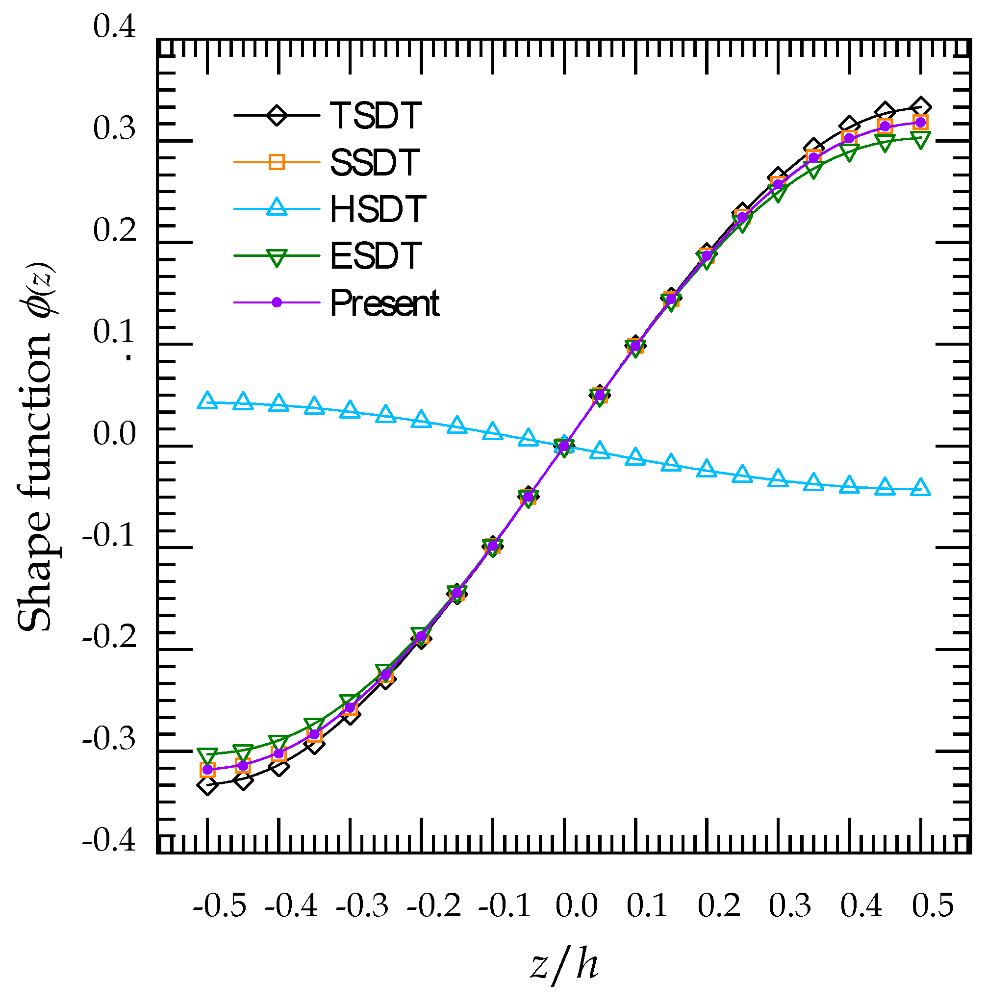
Figure 1. Geometry and cross-sections of FG-GRC laminated nanoplate. (a) plate geometry (b) gradation types (c) layer’s order.
Mathematics 10 01321 g001
Figure 2. Variation of shape functions Φ ( z ) through the thickness direction.
Mathematics 10 01321 g002
Figure 3. Dimensionless critical buckling load of simply supported GRNC plate under effect of: (a) Nonlocal parameter (b) Length-scale parameter, for various GPLs reinforcement patterns ( g GPL * = 1 % ) .
Mathematics 10 01321 g003
Figure 4. Dimensionless critical buckling load of simply supported GRNC plate in terms of number of layers for various GPLs reinforcement patterns ( g GPL * = 1 % ) .
Mathematics 10 01321 g004
Figure 5. Dimensionless critical buckling load of simply supported GRNC plate versus the length-to-thickness ratio of the GPLs nanofillers ( g GPL * = 1 % ) .
Mathematics 10 01321 g005
Figure 6. Dimensionless critical buckling load of simply supported GRNC plate versus the width-to-length ratio of the GPLs nanofillers ( g GPL * = 1 % ,   a GPL / h GPL = 10 2 ) .
Mathematics 10 01321 g006
Figure 7. Dimensionless critical buckling load versus aspect ratio of simply supported UD GRNC plate subjected to compressive biaxial in-plane load ( g GPL * = 1 % ,   χ 1 = 1 ) .
Mathematics 10 01321 g007
Figure 8. Influence of weight faction variation on dimensionless critical buckling load for various GPLs reinforcement patterns. (a) Full simply supported, (b) Full clamped supported, (c) Simply-Clamped-Simply-Clamped support, (d) Clamped-Clamped-Simply-Simply support.
Mathematics 10 01321 g008
Figure 9. Dimensionless central deflection of simply supported GRNC plate in terms of number of layers for various GPLs reinforcement patterns ( g GPL * = 1 % ) .
Mathematics 10 01321 g009
Figure 10. Effect of nonlocal and small-scale parameters on the dimensionless central deflection of simply supported GRNC plate for various GPLs reinforcement patterns ( g GPL * = 1 % ) .
Mathematics 10 01321 g010
Figure 11. Dimensionless central deflection of simply supported GRNC plate versus the length-to-thickness ratio of the GPLs nanofillers ( g GPL * = 1 % ) .
Mathematics 10 01321 g011
Figure 12. Dimensionless central deflection of simply supported GRNC plate versus the width-to-length ratio of the GPL nanofillers ( g GPL * = 1 % ,   a GPL / h GPL = 10 2 ) .
Mathematics 10 01321 g012
Figure 13. Dimensionless transverse displacement along the x-direction of the GRNC plate for various weight fractions g GPL *   ( b GPL / a GPL = 10 ) . (a) Full simply supported, (b) Full clamped supported, (c) Simply-Clamped-Simply-Clamped support, (d) Clamped-Clamped-Simply-Simply support.
Mathematics 10 01321 g013
Figure 14. Dimensionless in-plane displacement u ¯ through the thickness of simply supported GRNC plate for various GPLs reinforcement patterns ( g GPL * = 1 % ) .
Mathematics 10 01321 g014
Figure 15. Dimensionless transverse displacement w ¯ through the thickness of simply supported GRNC plate for various GPLs reinforcement patterns ( g GPL * = 1 % ) .
Mathematics 10 01321 g015
Figure 16. Dimensionless transverse displacement w ¯ of simply supported GRNC plate through the thickness of the UD GRNC plate for various weight fractions g GPL * .
Mathematics 10 01321 g016
Figure 17. Various dimensionless stresses through simply supported square GRNC plate thickness with different GPLs reinforcement patterns ( g GPL * = 1 % , a / h = 5 , a GPL = b GPL = 10 2   nm ,   a GPL = 0.7   nm ).
Mathematics 10 01321 g017
Table 1. Shear shape function distribution.
TheoryDescription Φ ( z )
Reddy [66] TSDT z ( 1 4 z 2 / 3 h 2 )
Touratier [67] SSDT h / π sin ( π z / h )
Soldatos et al. [68] HSDT z cos h ( 1 / 2 ) h sin h ( z / h )
Karama et al. [69]ESDT z e 2 ( z h ) 2
Present 5 h tan 1 ( z / h ) 4 z
Table 2. The admissible functions X m ( x ) and Y n ( y ) for different boundary conditions.
Boundary Conditions The   Functions   X m   and   Y n
At   x   =   0 ,   a At   y   =   0 ,   b X m ( x ) Y n ( y )
SSSS X m ( 0 ) = X m ( 0 ) = 0
X m ( a ) = X m ( a ) = 0
Y n ( 0 ) = Y n ( 0 ) = 0
Y n ( b ) = Y n ( b ) = 0
sin ( α x ) sin ( β y )
CCCC X m ( 0 ) = X m ( 0 ) = 0
X m ( a ) = X m ( a ) = 0
Y n ( 0 ) = Y n ( 0 ) = 0
Y n ( b ) = Y n ( b ) = 0
sin 2 ( α x ) sin 2 ( β y )
CCSS X m ( 0 ) = X m ( 0 ) = 0
X m ( a ) = X m ( a ) = 0
Y n ( 0 ) = Y n ( 0 ) = 0
Y n ( b ) = Y n ( b ) = 0
sin ( α x ) [ cos ( α x ) 1 ] sin ( β y ) [ cos ( β y ) 1 ]
SCSC X m ( 0 ) = X m ( 0 ) = 0
X m ( a ) = X m ( a ) = 0
Y n ( 0 ) = Y n ( 0 ) = 0
Y n ( b ) = Y n ( b ) = 0
sin 2 ( α x ) sin ( β y )
where λ = m π / a , μ = n π / b .
Table 3. Dimensionless critical buckling load ( × 10 2 ) of GRC plate subjected to a compressive uniaxial in-plane loading ( a GPL = 2.5   μ m ,   h GPL = 1.5   nm ,   w GPL = 1.5   μ m ) .
g G P L * ReferencesPattern
SSSSCCCCSCSC
UDFG-OFG-XUDFG-OFG-XUDFG-OFG-X
0.0Wu et al. [75]0.03100.03100.03100.06750.06750.06750.05200.05200.0520
Gholami [74]0.03110.03110.03110.06800.06800.06800.05230.05230.0523
Thai et al. [18]0.03090.03090.03090.07350.07350.0735
Present ε zz = 0 0.03100.03100.03100.07570.07570.07570.04920.04920.0492
Present ε zz 0 0.03180.03180.03180.08940.08940.08940.05640.05640.0564
0.1Wu et al. [75]0.04130.03660.04600.08990.08090.09840.06920.06220.0760
Gholami [74]0.04140.03680.04620.09060.08110.09870.06970.06260.0761
Thai et al. [18]0.04120.03760.04480.09800.09100.1044
Present ε zz = 0 0.04130.03760.04500.10090.09270.10830.06560.06010.0707
Present ε zz 0 0.04240.03850.04610.11900.10980.12720.07510.06900.0803
0.3Wu et al. [75]0.06190.04780.07580.13460.10720.15970.10370.08230.1235
Gholami [74]0.06200.04800.07590.13510.10840.15990.10410.08280.1238
Thai et al. [18]0.06180.05090.07260.14690.12520.1655
Present ε zz = 0 0.06200.05040.07280.15120.12590.17220.09830.08130.1130
Present ε zz 0 0.06350.05170.07450.17840.14960.20120.11250.09360.1283
0.5Wu et al. [75]0.08250.05880.10550.17940.13310.22070.13820.10210.1709
Gholami [74]0.08260.05920.10570.18010.13480.22110.13860.10260.1721
Thai et al. [18]0.08240.06410.10030.19570.15900.2262
Present ε zz = 0 0.08270.06320.10040.20160.15860.23530.13110.10220.1548
Present ε zz 0 0.08470.06480.10270.23760.18870.27410.14990.11790.1752
1Thai et al. [18]0.13380.09710.16950.31770.24280.3773
Present ε zz = 0 0.13420.09510.16900.32740.23990.39180.21280.15440.2586
Present ε zz 0 0.13750.09750.17290.38530.28560.38530.24320.17810.2915
Table 4. Dimensionless central deflection, normal stress and shear stress of square isotropic plate ( E c = 151   GPa ,   ν c = 0.3 ) .
w ¯ σ ¯ x x τ ¯ x z
ε z z = 0
Zenkour [58] FSDT0.196071.975760.19099
Zenkour [58] TSDT0.196062.049850.23857
Zenkour [58] SSDT0.196052.054520.24618
Neves [35] 0.19611.99470.2538
Present0.196052.054380.24634
ε z z 0
Zenkour [58]0.194872.007730.23910
Bessaim [77] 0.194861.995240.2461
Neves [78] 0.19492.00660.2459
Present0.194291.995470.24559
Table 5. Dimensionless critical buckling load of GRC plate subjected to a compressive uniaxial in-plane loading influenced by weight fraction g GPL * .
PatternTheory g G P L *
0.0%0.2%0.6%1.0%
ε z z   =   0 ε z z     0 ε z z   =   0 ε z z     0 ε z z   =   0 ε z z     0 ε z z   =   0 ε z z     0
UDTSDT3.10433.16383.15473.21513.25603.31813.35803.4218
SSDT3.10463.18113.15503.23263.25623.33613.35833.4402
HSDT3.10433.16383.15473.21503.25603.31813.35803.4218
ESDT3.10543.22773.15583.27973.25713.38433.35923.4895
Present3.10463.18033.15503.23183.25623.33523.35833.4393
FG-OTSDT3.10433.16383.13643.19663.20073.26213.26523.3279
SSDT3.10463.18113.13673.21413.20113.28033.26573.3467
HSDT3.10433.16383.13643.19653.20073.26203.26523.3278
ESDT3.10543.22773.13763.26133.20213.32853.26673.3959
Present3.10463.18033.13673.21333.20113.27953.26573.3459
FG-XTSDT3.10433.16383.17303.23373.31133.37423.45093.5160
SSDT3.10463.18113.17323.25113.31153.39183.45103.5338
HSDT3.10433.16383.17303.23363.31133.37423.45103.5160
ESDT3.10543.22773.17403.29823.31223.44013.45163.5831
Present3.10463.18033.17323.25023.31153.39103.45103.5329
FG-ATSDT3.10433.16383.15453.21503.25453.31723.35413.4194
SSDT3.10463.18113.15483.23253.25483.33513.35443.4377
HSDT3.10433.16383.15453.21493.25453.31723.35403.4194
ESDT3.10543.22773.15563.27963.25573.38333.35533.4869
Present3.10463.18033.15483.23173.25483.33433.35443.4368
Table 6. Dimensionless critical buckling load of GRNC plate under various boundary conditions subjected to a compressive uniaxial/biaxial in-plane loading ( g GPL * = 1 % ) .
PatternTheoryBoundary Conditions
SSSSCCCCSCSCCCSS
ε z z   =   0 ε z z     0 ε z z   =   0 ε z z     0 ε z z   =   0 ε z z     0 ε z z   =   0 ε z z     0
Uniaxial in-plane loading ( χ 1 = 1 .   χ 2 = 0 )
UDTSDT3.35803.42188.18829.61575.32426.06496.50047.1422
SSDT3.35833.44028.19039.64145.32536.08436.50177.1718
HSDT3.35803.42188.18829.61505.32426.06456.50047.1417
ESDT3.35923.48958.195989.70085.32826.13206.50517.2442
Present3.35833.43938.19039.64055.32536.08356.50167.1706
FG-OTSDT3.26523.32797.99329.40905.19135.92526.33696.9712
SSDT3.26573.34677.99659.43635.19305.94556.338967.0018
HSDT3.26523.32787.99319.40825.19125.92486.33686.9706
ESDT3.26673.39598.00319.49675.19655.99376.34307.0745
Present3.26573.34597.99659.43535.19305.94476.33897.0006
FG-XTSDT3.45093.51608.38099.81825.45616.20266.66277.3114
SSDT3.45103.53388.38159.84195.45646.22096.66307.3398
HSDT3.45103.51608.38109.81785.45626.20246.66287.3111
ESDT3.45163.58318.38599.89975.45876.26786.66577.4115
Present3.45103.53298.38159.84085.45636.22006.66307.3385
FG-ATSDT3.35413.41948.17969.60775.31846.05996.49337.1367
SSDT3.35443.43778.18179.63345.31956.07936.49457.1662
HSDT3.35403.41948.17969.60715.31846.05966.49337.1362
ESDT3.35533.48698.18739.69265.32246.12686.49807.2385
Present3.35443.43688.18179.63235.319476.07846.49457.1650
Biaxial in-plane loading ( χ 1 = 1 .   χ 2 = 1 )
UDTSDT1.67901.71094.09414.80783.04243.46563.25023.5711
SSDT1.67911.72014.09524.82073.04303.47673.25083.5859
HSDT1.67901.71094.09414.80753.04243.46543.250193.5709
ESDT1.67961.74484.09804.85043.04473.50403.252563.6221
Present1.67911.71974.09524.82023.04303.47633.25083.5853
FG-OTSDT1.63261.66403.99664.70452.96653.38583.16853.4856
SSDT1.63291.67333.99834.71822.96753.39743.16953.5009
HSDT1.63261.66393.99654.70412.96643.38553.16843.4853
ESDT1.63341.69794.00154.74842.96943.42493.17153.5373
Present1.63291.67293.99834.71772.96743.39703.16953.5003
FG-XTSDT1.72551.75804.19054.90913.117763.54433.33133.6557
SSDT1.72551.76694.19084.92093.11793.55483.33153.6699
HSDT1.72551.75804.19054.90893.11783.54423.33143.6555
ESDT1.72581.79154.19294.94993.11923.58163.33293.7057
Present1.72551.76654.19074.92043.11793.55433.33153.6692
FG-ATSDT1.67701.70974.08984.80383.03913.46283.24673.5684
SSDT1.67721.71884.09094.81673.03973.47393.24733.5831
HSDT1.67701.70974.08984.80353.03913.46263.24663.5681
ESDT1.67761.74344.09374.84633.04143.50103.24903.6192
Present1.67721.71844.09084.81623.03973.47343.24733.5825
Table 7. Effect of nonlocal and small-scale parameters on dimensionless critical buckling load of GRC plate subjected to a compressive uniaxial in-plane loading ( g GPL * = 1 % ) .
Pattern μ   ( n m 2 ) λ   ( n m 2 )
012345
UD03.43933.44103.44273.44443.44613.4478
13.43763.43933.44103.44273.44443.4461
23.43593.43763.43933.44103.44273.4444
33.43433.43603.43763.43933.44103.4427
43.43263.43433.43603.43763.43933.4410
53.43093.43263.43433.43603.43763.4393
FG-O03.34593.34753.34923.35083.352473.3541
13.34423.34593.34753.34923.35083.3525
23.34263.34423.34593.34753.349163.3508
33.34093.34263.34423.34593.34753.3492
43.33933.34093.34263.34423.34593.3475
53.33763.33933.34093.34263.34423.3459
FG-X03.53293.53473.53643.53823.53993.5417
13.53123.53293.53473.53643.53823.5399
23.52953.53123.53303.53473.53643.5382
33.52773.52953.53123.53293.53473.5364
43.52603.52773.52953.53123.53293.5346
53.52423.52603.52773.52943.53123.5329
FG-A03.43683.43853.44023.44193.44363.4453
13.43513.43683.43853.44023.44193.4436
23.43343.43513.43683.43853.44023.4419
33.43183.43353.43513.43683.43853.4402
43.43013.43173.43343.43513.43683.4385
53.42843.43013.43183.43353.43513.4368
Table 8. Effect of the total number of layers on dimensionless critical buckling load of FG-O GRC plate subjected to a compressive biaxial in-plane loading ( g GPL * = 1 % ) .
a/hb/a N L
2468101214161820
50.512.522112.455912.426612.411612.402712.396812.392612.389512.387112.3851
16.15086.07626.04956.03616.02816.02276.01896.01616.01396.0121
24.06204.00353.98333.97313.96703.96303.96013.95803.95633.9549
33.64833.59423.57563.56623.56063.55693.55423.55223.55073.5494
100.54.06204.00353.98333.97313.96703.96303.96013.95803.95633.9549
11.71971.69061.68081.67591.67291.67101.66961.66851.66771.6676
21.09041.07131.06481.06161.05971.05841.05751.05681.05631.0558
30.97190.95470.94890.94600.94430.94310.94230.94170.94120.9408
200.51.09041.07131.06481.06161.05971.05841.05751.05681.05631.0558
10.44260.43450.43180.43040.42960.42910.42870.42840.42820.4280
20.27760.27250.27080.26990.26940.26910.26880.26870.26850.2684
30.24690.24240.24070.24010.23960.23930.23910.23900.23880.2387
300.50.49120.48230.47930.47780.47690.47630.47590.47550.47530.4751
10.19780.19410.19290.19230.19190.19170.19150.19130.19130.1912
20.12380.12150.12070.12030.12010.12000.11990.11980.11970.1197
30.11090.10800.10730.10700.10680.10670.10660.10650.10640.1064
Table 9. Dimensionless displacements and stresses of simply supported square GRC plate for various GPLs reinforcement patterns ( g GPL * = 1 % ) .
PatternTheory u ¯ w ¯ σ ¯ x x σ ¯ x y σ ¯ x z
UDTSDT ε z z = 0 0.06558.89512.05411.01570.2386
ε z z 0 0.05488.83082.06991.00400.2385
SSDT ε z z = 0 0.06468.89432.05541.01640.2462
ε z z 0 0.05388.78682.25640.99920.2449
HSDT ε z z = 0 0.06568.89512.05401.01570.2379
ε z z 0 0.05498.83052.05271.00390.2379
ESDT ε z z = 0 0.06348.89192.05661.01690.2538
ε z z 0 0.05298.66292.41040.98520.2511
Present ε z z = 0 0.06468.89432.05541.01630.2463
ε z z 0 0.05388.78912.24060.99940.2451
FG-OTSDT ε z z = 0 0.06419.14772.01240.99250.2459
ε z z 0 0.05319.08072.02990.98090.2459
SSDT ε z z = 0 0.06319.14632.01360.99310.2534
ε z z 0 0.05209.03272.21650.97600.2520
HSDT ε z z = 0 0.06429.14782.01230.99240.2452
ε z z 0 0.05329.08062.01260.98090.2453
ESDT ε z z = 0 0.06199.14342.01470.99360.2608
ε z z 0 0.05118.90172.36990.96190.2580
Present ε z z = 0 0.06319.14632.01360.99310.2535
ε z z 0 0.05209.03502.20090.97620.2522
FG-XTSDT ε z z = 0 0.06698.65552.09381.03800.2310
ε z z 0 0.05668.59372.10801.02610.2310
SSDT ε z z = 0 0.06618.65542.09511.03870.2388
ε z z 0 0.05568.55372.29411.02150.2377
HSDT ε z z = 0 0.06708.65542.09361.03800.2303
ε z z 0 0.05678.59332.09081.02600.2304
ESDT ε z z = 0 0.06508.65372.09641.03940.2466
ε z z 0 0.05488.43662.44851.00750.2441
Present ε z z = 0 0.06618.65542.09511.03870.2390
ε z z 0 0.05568.55592.27811.02180.2378
FG-ATSDT ε z z = 0 0.09568.90542.13390.97360.2368
ε z z 0 0.07638.83692.13940.95590.2368
SSDT ε z z = 0 0.09478.90462.13530.97420.2444
ε z z 0 0.07528.79312.33530.95140.2432
HSDT ε z z = 0 0.09578.90542.13380.97350.2361
ε z z 0 0.07648.83672.12130.95580.2362
ESDT ε z z = 0 0.09358.90232.13660.97470.2519
ε z z 0 0.07428.66932.49710.93830.2493
Present ε z z = 0 0.09478.90472.13520.97420.2445
ε z z 0 0.07528.79542.31870.95160.2433
Table 10. Dimensionless displacements of GRC plate under various boundary conditions influenced by weight fraction g GPL * .
Pattern g GPL * Boundary Conditions
SSSSCCCCSCSCCCSS
ε z z   =   0 ε z z     0 ε z z   =   0 ε z z     0 ε z z   =   0 ε z z     0 ε z z   =   0 ε z z     0
Epoxy0.0%9.62119.50585.26104.51706.06835.36751.98811.8313
UD0.1%9.54379.42955.21864.48196.01945.32551.97211.8168
0.2%9.46749.35435.17684.44725.97125.28401.95631.8025
0.6%9.17299.06395.01534.31325.78515.12391.89531.7474
1.0%8.89438.78914.86264.18645.60904.97241.83771.6952
FG-O0.1%9.57169.45685.23164.49196.03515.33831.97731.8214
0.2%9.52269.40815.20254.46716.00245.30941.96661.8115
0.6%9.33109.21825.08914.37045.87465.19681.92491.7733
1.0%9.14639.03504.98044.27795.75185.08881.88481.7366
FG-X0.1%9.51609.40255.20574.47196.00375.31271.96691.8123
0.2%9.41299.30115.15144.42765.94045.25901.94611.7936
0.6%9.02008.91474.94424.25825.69885.05371.86681.7224
1.0%8.65548.55594.75174.10065.47434.86281.79311.6562
FG-A0.1%9.54389.42965.21874.48196.01945.32551.97211.8168
0.2%9.46799.35465.17704.44735.97155.28421.95641.8026
0.6%9.17709.06645.01734.31465.78755.12551.89611.7479
1.0%8.90478.79544.86774.18985.61514.97641.83971.6965
Table 11. Effect of nonlocal and small-scale parameters on dimensionless central deflection of GRC plate subjected to a compressive uniaxial in-plane loading ( g GPL * = 1 % ) .
Pattern μ λ
012345
UD08.78918.78488.78058.77628.77188.7675
18.79358.78918.78488.78058.77628.7718
28.79788.79358.78918.78488.78058.7762
38.80228.79788.79358.78918.78488.7805
48.80658.80228.79788.79358.78918.7848
58.81088.80658.80218.79788.79358.7891
FG-O09.03509.03069.02619.02179.01729.0128
19.03959.03509.03069.02619.02179.0173
29.04409.03959.03509.03069.02619.0217
39.04849.04409.03959.03509.03069.0262
49.05299.04849.04409.03959.03509.0306
59.05739.05299.04849.04409.03959.0350
FG-X08.55598.55178.54758.54338.53918.5349
18.56028.55598.55178.54758.54338.5391
28.56448.56028.55598.55178.54758.5433
38.56868.56448.56028.55598.55178.5475
48.57288.56868.56448.56028.55598.5517
58.57718.57288.56868.56448.56028.5559
FG-A08.79548.79118.78688.78248.77818.7738
18.79988.79548.79118.78688.78248.7781
28.80418.79988.79548.79118.78688.7824
38.80858.80418.79988.79548.79118.7868
48.81288.80848.80418.79988.79548.7911
58.81718.81288.80848.80418.79988.7954
Publisher’s Note: MDPI stays neutral with regard to jurisdictional claims in published maps and institutional affiliations.

