
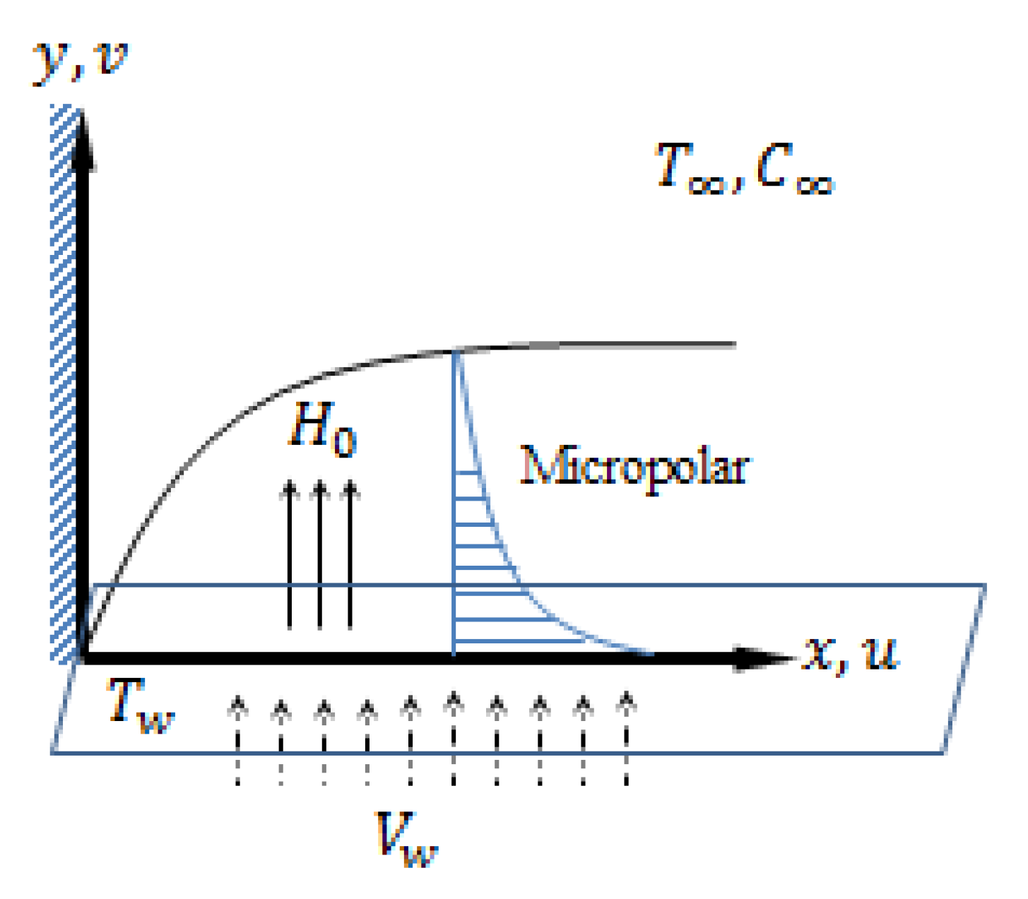
Thermal Conductivity and Thermophoretic Impacts of Micropolar Fluid Flow by a Horizontal Absorbent Isothermal Porous Wall with Heat Source/Sink


Abstract
:1. Introduction
2. Flow Equations Analysis
3. Results and Discussion
4. Conclusions
- An augmentation in results in the thermophoretic forces that encapsulate the mass transmission.
- An enhancement in the magnetic field factor has the same impact on the flow distribution as an increment in viscosity.
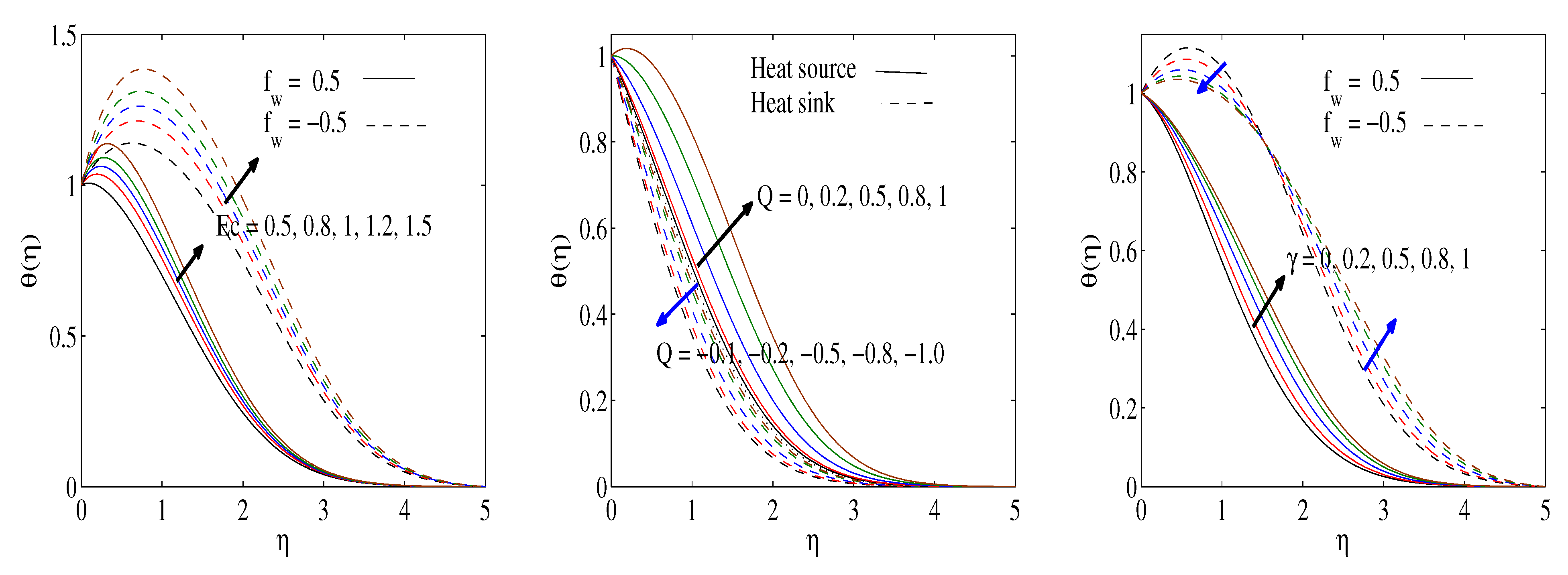
- The local Nusselt number strengthened as the thermal conductivity, heat absorption factors or wall suction velocity were boosted, and weakened due to the existence of either heat generation or viscous dissipation impacts.
- The temperature profiles boost with enlarging Eckert numbers, porosity and magnetic factors.
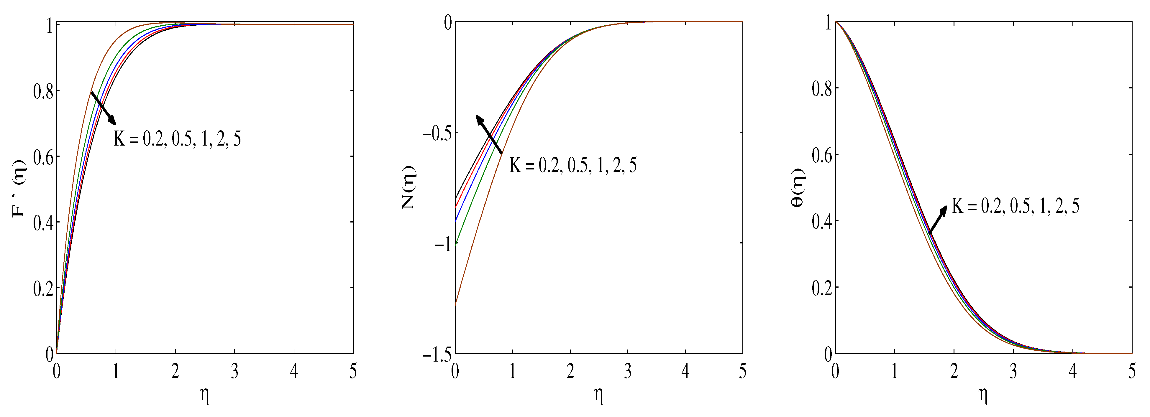
- The coupling factor leads to amplifying skin friction and couple stress while lessening the Nusselt number.
- Heat source results in a thicker boundary layer, while heat sink leads to a thinner thermal boundary layer.
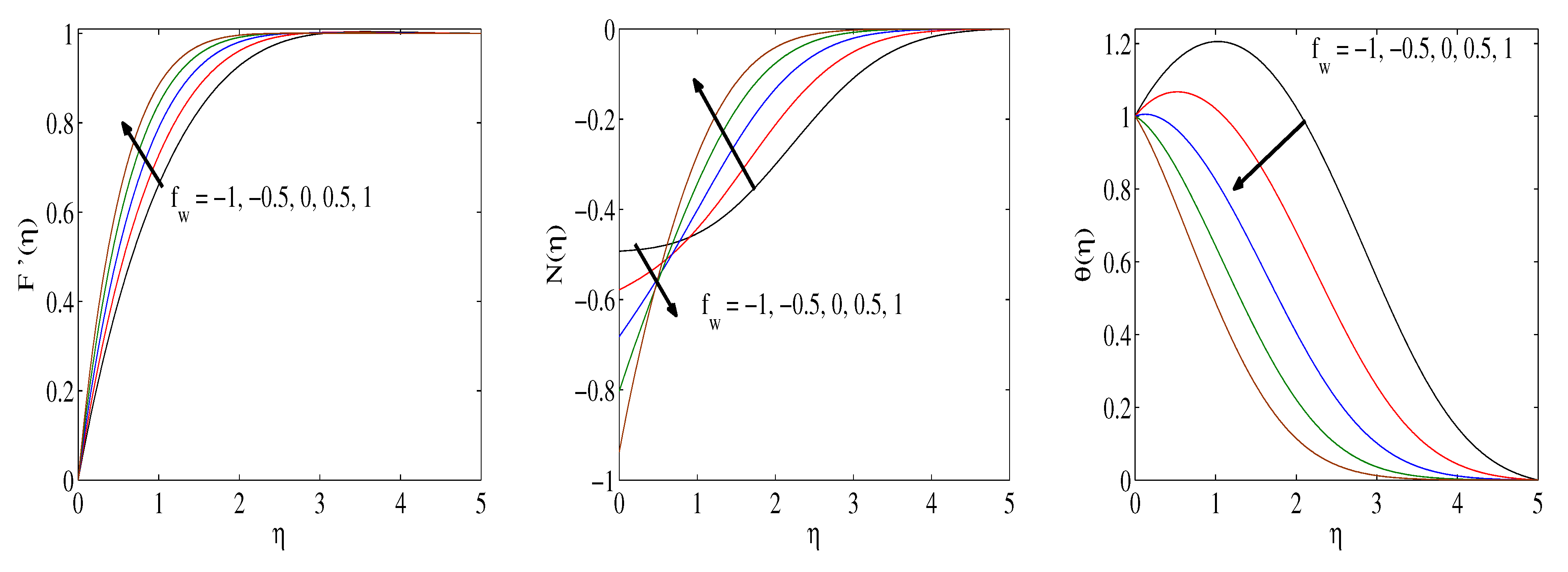
- The microrotation fluctuations are enhanced in the case of strong () and low () concentrations and are weakened in the case of a very low () concentration.
Author Contributions
Funding
Institutional Review Board Statement
Informed Consent Statement
Data Availability Statement
Conflicts of Interest
Nomenclature
| C | Concentration | Reynolds number | |
| Skin friction | Schmidt number | ||
| Eckert number | Sherwood number | ||
| F | Dimensionless stream function | T | Temperature |
| Suction/blowing flow factor | Velocity components | ||
| g | Gravity acceleration | Cartesian axes | |
| Hartmann number | Greek letters | ||
| Magnetic field intensity | Effective dynamic viscosity | ||
| j | Microinertial factor | Kinematic viscosity | |
| k | Thermal conductivity | Viscosity of spin gradient | |
| Dimensional porosity factor | Thermophoretic factor | ||
| K | Dimensionless porosity factor | Dimensionless temperature | |
| m | Microrotation factor | Dimensionless concentration | |
| N | Dimensionless angular velocity | Stream function | |
| Couple stress factor | Micropolar coupling factor | ||
| Nusselt number | Similarity variable | ||
| Pr | Prandtl number | Vortex viscosity | |
| Q | Dimensionless heat source/sink factor | Active fluid density | |
| Dimensional heat source/sink factor | Variable thermal conductivity factor |
References
- Agarwal, R.S.; Dhanapal, C. Flow and heat transfer in a micropolar fluid past a flat plate with suction and heat sources. Int. J. Eng. Sci. 1988, 26, 1257–1266. [Google Scholar] [CrossRef]
- Turkyilmazoglu, M. Mixed convection flow of magnetohydrodynamicmicropolar fluid due to a porous heated/cooled de-formable plate: Exact solutions. Int. J. Heat Mass Transf. 2017, 106, 127–134. [Google Scholar] [CrossRef]
- Mahdy, A. Aspects of homogeneous-heterogeneous reactions on natural convection flow of micropolar fluid past a permeable cone. Appl. Math. Comput. 2019, 352, 59–67. [Google Scholar] [CrossRef]
- Nazar, R.; Amin, N.; Grosan, T.; Pop, I. Free convection boundary layer on a sphere with constant surface heat flux in a micropolar fluid. Int. Commun. Heat Mass Transf. 2002, 29, 1129–1138. [Google Scholar] [CrossRef]
- Ahmadi, G. Self-similar solution of incompressible micropolar boundary layer flow over a semi-infinite flat plate. Int. J. Eng. Sci. 1976, 14, 639–646. [Google Scholar] [CrossRef]
- Takhar, H.S.; Agarwal, R.S.; Bhargava, B.; Jain, S. Mixed convection flow of a micropolar fluid over a stretching sheet. Heat Mass Transf. 1998, 34, 213–219. [Google Scholar] [CrossRef]
- Ali, K.; Iqbal, M.F.; Akbar, Z.; Ashraf, M. Numerical simulation of unsteady water-based nanofluid flow and heat transfer between two orthogonally moving porous coaxial disks. J. Theor. Appl. Mech. 2014, 52, 1033–1046. [Google Scholar] [CrossRef] [Green Version]
- Nabwey, H.A.; Mahdy, A. Transient flow of micropolar dusty hybrid nanofluid loaded with Fe3O4-Ag nanoparticles through a porous stretching sheet. Res. Phy. 2021, 21, 103777. [Google Scholar] [CrossRef]
- Rundora, L.; Makinde, O.D. Unsteady MHD flow of non-Newtonian fluid in a channel filled with a saturated porous medium with asymmetricnavier slip and convective heating. Appl. Math. Inform. Sci. Int. J. 2018, 12, 483–493. [Google Scholar] [CrossRef]
- Eringen, A.C. Theory of micropolar fluids. J. Math. Mech. 1966, 16, 1–18. [Google Scholar] [CrossRef]
- Eringen, A.C. Theory of thermomicropolar fluids. J. Math. Appl. 1972, 38, 480–495. [Google Scholar]
- Ariman, T.; Turk, M.A.; Sylvester, N.D. Microcontinuum fluid mechanics—A review. Int. J. Eng. Sci. 1973, 11, 905–930. [Google Scholar] [CrossRef]
- Nabwey, H.A.; Mahdy, A. Numerical approach of micropolar dust-particles natural convection fluid flow due to a permeable cone with nonlinear temperature. Alex. Eng. J. 2021, 60, 1739–1749. [Google Scholar] [CrossRef]
- Ali, K.; Ahmad, A.; Ashraf, M. Numerical simulation of flow and heat transfer in hydromagnetic micropolar fluid between two stretchable disks with viscous dissipation effects. J. Theor. Appl. Mech. 2016, 54, 633–643. [Google Scholar] [CrossRef] [Green Version]
- Ali, K.; Ashraf, M. Numerical simulation of the micropolar fluid flow and heat transfer in a channel with a shrinking and a stationary wall. J. Theor. Appl. Mech. 2014, 52, 557–569. [Google Scholar]
- Hazarika, S.; Ahmed, S. Numerical investigation of endothermic/exothermic reactionin MHD natural Convective nano-fluid flow over a vertical cone with heat source/sink. Walailak J. Sci. Technol. 2021, 18, 22834-18. [Google Scholar] [CrossRef]
- Hazarika, S.; Ahmed, S. Brownian motion and thermophoresis behavior on micropolar nano-fluid-A numerical outlook. Math. Comput. Simul. 2022, 192, 452–463. [Google Scholar] [CrossRef]
- Tsai, R. A simple approach for evaluating the effect of wall suction and thermophoresis on aerosol particle deposition from a laminar flow over a flat plate. Int. Commun. Heat Mass Transf. 1999, 26, 249–257. [Google Scholar] [CrossRef]
- Talbot, L.; Cheng, R.K.; Scheffer, R.W.; Wills, D.P. Thermophoresis of particles in a heated boundary layer. J. Fluid Mech. 1980, 101, 737–758. [Google Scholar] [CrossRef] [Green Version]
- Chamkha, A.J.; Camille, I. Effects of heat generation/absorption and thermophoresis on hydromagnetic flow with heat and mass transfer over a flat surface. Int. J. Numer. Methods Heat Fluid Flow 2012, 10, 432–448. [Google Scholar] [CrossRef] [Green Version]
- Ahmed, S.A.; Mahdy, A. Unsteady MHD double diffusive convectionin the stagnation region of an impulsively rotating sphere in the presenceof thermal radiation effect. J. Taiwan Institu. Chem. Eng. 2016, 58, 173–180. [Google Scholar] [CrossRef]
- Mahdy, A. Unsteady MHD slip flow of a non-Newtonian Casson fluiddue to stretching sheet with suction or blowing effect. J. Appl. Fluid Mech. 2016, 9, 785–793. [Google Scholar]
- Waqas, M.; Farooq, M.; Khan, M.I.; Alsaedi, A.; Hayat, T.; Yasmeen, T. Magnetohydrodynamic (MHD) mixed convection flow of micropolar liquid due to nonlinear stretched sheet with convective condition. Int. J Heat Mass Transf. 2016, 102, 766–772. [Google Scholar] [CrossRef]
- Rana, B.M.J.; Arifuzzaman, S.M.; Reza-E-Rabbi, S.; Ahmmed, S.F.; Khan, M.S. Energy and magnetic flow analysis of Williamson micropolar nanofluid through stretching sheet. Int. J. Heat Technol. 2019, 37, 487–496. [Google Scholar] [CrossRef] [Green Version]
- Mahdy, A.; Ahmed, S.A. Unsteady MHD convective flow ofnon-Newtonian Casson fluid in the stagnation region of an impulsively rotating sphere. J. Aerosp. Eng. 2017, 30, 04017036. [Google Scholar] [CrossRef]
- Sheri, S.R.; Shamshuddin, M.D. Heat and mass transfer on the MHD flow of micropolar fluid in the presence of viscous dissipation and chemical reaction. Procedia Eng. 2015, 127, 885–892. [Google Scholar] [CrossRef] [Green Version]
- Shehzad, S.A.; Hayat, T.; Alsaedi, A. MHD flow of Jeffrey nanofluidwith convective boundary conditions. J. Braz. Soc. Mech. Sci. Eng. 2015, 37, 873–883. [Google Scholar] [CrossRef]
- Rashad, A.M.; Khan, W.A.; EL-Kabeir, S.M.M.; EL-Hakiem, A.M.A. Mixed convective flow of micropolar nanofluid across a horizontal cylinder in saturated porous medium. Appl. Sci. 2019, 9, 5241. [Google Scholar] [CrossRef] [Green Version]
- Arifuzzaman, S.M.; Khan, M.S.; Mehedi, M.F.U.; Rana, B.M.J.; Ahmmed, S.F. Chemically reactive and naturally convective high-speed MHD fluid flow through an oscillatory vertical porous-plate with heat and radiation absorption effect. Eng. Sci. Technol. Int. J. 2018, 21, 215–228. [Google Scholar] [CrossRef]
- Mahdy, A.; Chamkha, A.J. Unsteady MHD boundary layer flow of tangent hyperbolic two-phase nanofluid of moving stretched porous wedge. Int. J. Numer. Methods Heat Fluid Flow 2018, 28, 2567–2580. [Google Scholar] [CrossRef] [Green Version]
- Syakila, A.; Pop, I. Mixed convection boundary layer flow from a vertical flat plate embedded in a porous medium filled with nanofluids. Int. Commun. Heat Mass Transf. 2010, 37, 987–991. [Google Scholar]
- Zehba, A.S.R.; Aly, A.M.; Ahmed, S.E. Natural convection flow of a nanofluid-filled V-shaped cavity saturated with a heterogeneous porous medium: Incompressible smoothed particle hydrodynamics analysis. Ain Shams Eng. J. 2021, 12, 2033–2046. [Google Scholar]
- Seth, G.S.; Bhattacharyya, A.; Kumar, R.; Mishra, M.K. Modeling and numerical simulation of hydromagnetic natural convection Casson fluid flow with nth-order chemical reaction and Newtonian heating in porous medium. J. Porous Media 2019, 22, 1141–1157. [Google Scholar] [CrossRef]
- Khedr, M.E.M.; Chamkha, A.J.; Bayomi, M. MHD flow of a micropolar fluid past a stretched permeable surface with heat gen-eration or absorption. Nonlinear Anal. Model. Control 2017, 14, 27–40. [Google Scholar] [CrossRef] [Green Version]
- Hayat, T.; Ali, S.; Awais, M.; Alsaedi, A. Joule heating effects in MHD flow of Burger’s fluid. Heat Transf. Res. 2016, 47, 1083–1092. [Google Scholar] [CrossRef]
- Alreshidi, N.A.; Shah, Z.; Dawar, A.; Kumam, P.; Shutaywi, M.; Watthayu, W. Brownian motion and thermophoresis effects on MHD three dimensional nanofluid flow with slip conditions and Joule dissipation due to porous rotating disk. Molecules 2020, 25, 729. [Google Scholar] [CrossRef] [Green Version]
- Hayat, T.; Qasim, M. Influence of thermal radiation and Joule heating on MHD flow of a Maxwell fluid in the presence of thermophoresis. Int. J. Heat Mass Transf. 2010, 53, 4780–4788. [Google Scholar] [CrossRef]
- Shah, Z.; McCash, L.B.; Dawar, A.; Bonyah, E. Entropy optimization in Darcy-Frochheimer mhd flow of water based copper and silvernanofluids with Joule heating and viscous dissipation effects. AIP Adv. 2020, 10, 065137. [Google Scholar] [CrossRef]
- Sandeep, N.; Sulochana, C. Dual solutions for unsteady mixed convective flow of MHD micropolar fluid over a stretching/shrinking sheet with non-uniformheat source/sink. Eng. Sci. Technol. Int. J. 2015, 18, 738–745. [Google Scholar]
- Thumma, T.; Mishra, S.R. Effect of nonuniform heat source/sink, and viscous and Joule dissipation on 3D Eyring—Powell nanofluid flow over a stretching sheet. J. Comput. Des. Eng. 2020, 7, 412–426. [Google Scholar] [CrossRef]
- Rout, B.; Mishra, S.; Thumma, T. Effect of viscous dissipation on Cu-water and Cu-kerosene nanofluids of axisymmetric radiative squeezing flow. Heat Transf. Asian Res. 2019, 48, 3039–3054. [Google Scholar] [CrossRef]
- Naganthran, K.; Basir, M.; Thumma, T.; Olubunmi, E.; Nazar, R.; Tlili, I. Scaling group analysis of bioconvective micropolar fluid flow and heat transfer in a porous medium. J. Therm. Anal. Calorim. 2021, 143, 1943–1955. [Google Scholar] [CrossRef]
- Thumma, T.; Magagula, V.M. Transient electromagnetohydrodynamic radiative squeezing flow between two parallel Riga plates using a spectral local linearization approach. Heat Transf. Asian Res. 2019, 49, 67–85. [Google Scholar] [CrossRef]
- Higham, D.J.; Higham, N.J. MATLAB Guide; SIAM: New Delhi, India, 2005. [Google Scholar]


| Chamkha and Camille [20] | Tsai [18] | Present | ||
|---|---|---|---|---|
| 0.5 | 0.02 | −0.967014 | −0.967530 | −0.966182 |
| 0.20 | −0.983710 | −0.984805 | −0.984291 | |
| 2.00 | −1.152172 | −1.152437 | −1.152257 | |
| −0.5 | 0.02 | −0.354171 | −0.354261 | −0.352051 |
| 0.20 | −0.367250 | −0.367710 | −0.367207 | |
| 2.00 | −0.548181 | −0.548312 | −0.547344 |
Publisher’s Note: MDPI stays neutral with regard to jurisdictional claims in published maps and institutional affiliations. |
© 2022 by the authors. Licensee MDPI, Basel, Switzerland. This article is an open access article distributed under the terms and conditions of the Creative Commons Attribution (CC BY) license (https://creativecommons.org/licenses/by/4.0/).
Share and Cite
Nabwey, H.A.; Rashad, A.M.; Mahdy, A.E.N.; Shaaban, S.M. Thermal Conductivity and Thermophoretic Impacts of Micropolar Fluid Flow by a Horizontal Absorbent Isothermal Porous Wall with Heat Source/Sink. Mathematics 2022, 10, 1514. https://doi.org/10.3390/math10091514
Nabwey HA, Rashad AM, Mahdy AEN, Shaaban SM. Thermal Conductivity and Thermophoretic Impacts of Micropolar Fluid Flow by a Horizontal Absorbent Isothermal Porous Wall with Heat Source/Sink. Mathematics. 2022; 10(9):1514. https://doi.org/10.3390/math10091514
Chicago/Turabian StyleNabwey, Hossam A., Ahmed M. Rashad, Abd El Nasser Mahdy, and Shaaban M. Shaaban. 2022. "Thermal Conductivity and Thermophoretic Impacts of Micropolar Fluid Flow by a Horizontal Absorbent Isothermal Porous Wall with Heat Source/Sink" Mathematics 10, no. 9: 1514. https://doi.org/10.3390/math10091514