1. Introduction
In comparison to conventional materials which have homogenous microstructures, functionally graded materials (FGMs) have heterogeneous constituents and their properties vary continuously along spatial direction(s) [
1]. FGMs can be designed to achieve the required mechanical, thermal, electrical, and magnetic properties by grading their constituents with suitable metal/ceramics materials. FGM was originated during the space-plane project in Japan, 1984 [
2]. Currently, FGMs are used in many real applications such as aerospace, biomechanics, medical devices [
3], marine, heat exchanger [
4], MEMS and NEMS [
5], shape memory alloys, thin films, and AFM [
6].
In some applications such as aerospace craft, nuclear and shuttles, distributions of the stress or thermal field in the structural elements of such advanced machines can be in two or three directions, and thus, the conventional 1D FGMs are not sufficient. As a consequence, there is a need for multi-directional FGMs [
7]. Nemat-Alla [
8] proposed a 2D (two directional) FGM which withstands super-high temperatures and gives more reduction in thermal stress. Lu et al. [
9] exploited the state space-based differential quadrature method to derive semi-analytical 3D elasticity solutions for multi-directional orthotropic FG plates. Pan [
10] developed an enriched improved complex variable element-free Galerkin method for efficient fracture analysis of orthotropic materials. Esmaeilzadeh et al. [
11,
12] exploited the dynamic relaxation method in analyzing the dynamic of stiffened 2D FG porous plates under a moving load. Do et al. [
13] exploited a non-uniform rational B-spline basis function for describing material distribution varying through 3D FG plates and used natural frequency or buckling load as the objective function for maximization. Ghatage et al. [
14] presented an exhaustive review on modelling and analysis of multi-directional FG beam/plate/shell structures.
Chen et al. [
15] studied the nonlinear forced vibration of the bi-directional functionally graded (BDFG) plate with global and localized geometrical imperfections by using the pseudo-arclength continuation technique. Li et al. [
16] studied buckling and post-buckling performance of variable stiffness composite plates with cutouts via classical plate theory with the nonlinear von Karman strain. Luo et al. [
17] presented buckling analysis of variable stiffness composite plates with elliptical cutouts using an efficient radial basis point interpolation method based on a naturally stabilized nodal integration scheme. Karamanli et al. [
18] developed a finite element model to study the mechanical responses of multi-directional FG strain gradient microplates using a quasi-3D shear theory. Assie et al. [
7] developed a computational model based on unified higher order shear theories to evaluate the static buckling of BDFG porous plates resting on elastic foundation based on unified shear theories.
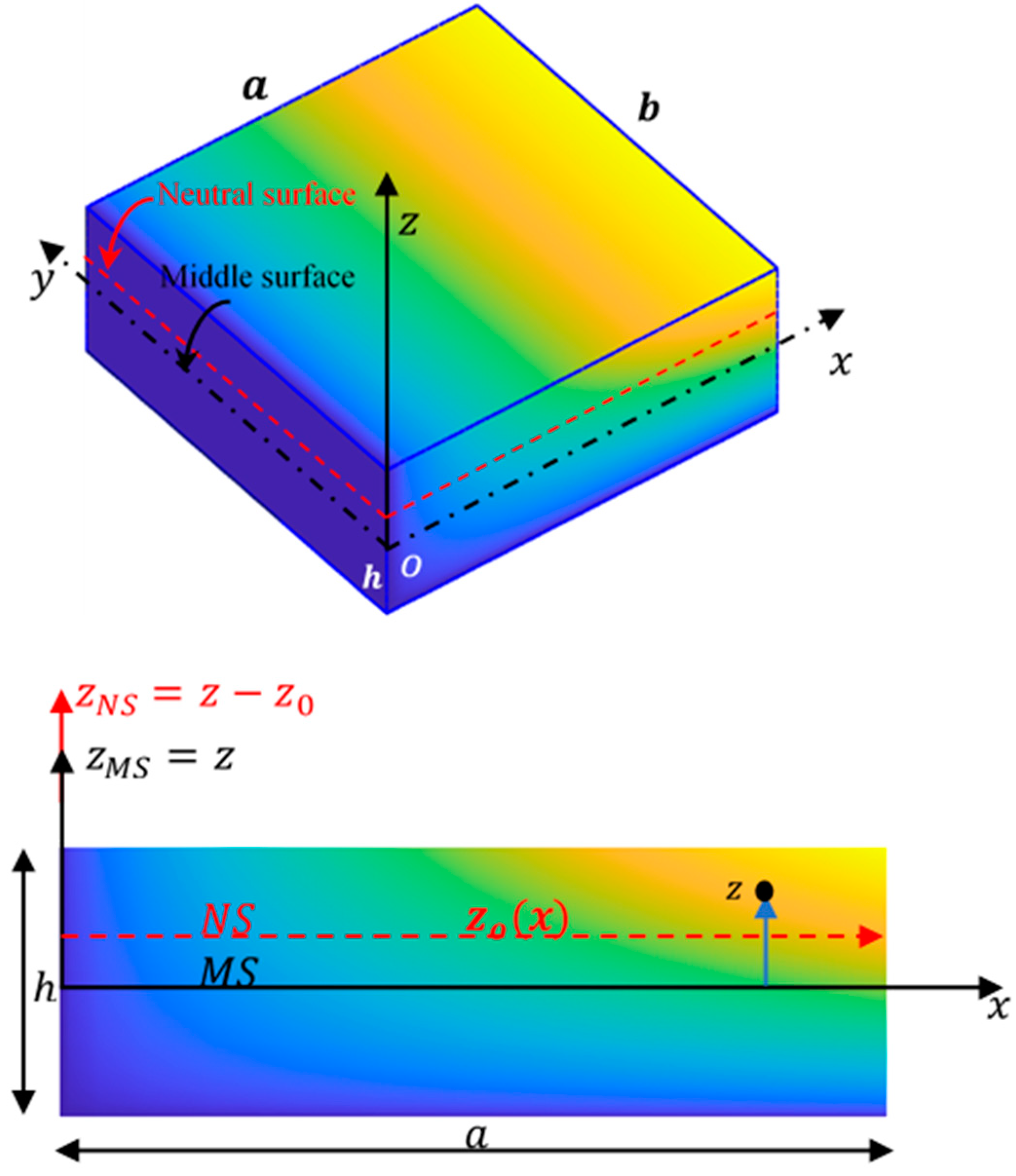
The mid-surface and neutral surface overlay in a homogeneous isotropic plate, while it is the case for the FGMs plate, is not in this case because material properties are graded through the thickness [
19]. Hence, there is a strong scientific need to reexamine behaviors of FG structures about the undeformed neutral plane [
20,
21,
22]. The concept of neutral surface that was employed for many analyses leads to more accurate formulation and numerical results [
23]. In 2008, Zhang and Zhou [
24] derived the governing equations of a FGM thin rectangular plate based on the physical neutral surface and classical laminated plate theory. Zhang [
25] studied post-buckling, nonlinear bending and vibration of FGM plates based on a physical neutral surface and high order shear deformation theory. Han et al. [
26] and Benferhat et al. [
27] examined dynamic instability of the FGM plate on an elastic medium based on the exact neutral surface position. Barati and Shahverdi [
28] presented an analytical solution for thermo-mechanical vibration of FG nanoplates under uniform, linear and non-linear temperature rise considering a neutral surface. Farzam-Rad et al. [
29] developed a simple quasi-3D shear theory in analyzing a static and free vibration response of FG sandwich plates by using the isogeometric analysis and physical neutral surface. Arefi et al. [
23] exploited two-variable sinusoidal shear deformation theory in analyzing the free vibration of a sandwich piezo-elastic nonlocal nanoplate incorporating the neutral surface effect. Lie et al. [
30] exploited classical plate theory with the von Karman strain to model large amplitude vibration of matrix cracked hybrid laminated plates containing CNTR-FG layers. Zarastvand et al. [
31] presented a comprehensive review on the prediction of acoustic wave transmission features of the multilayered plate. Ghafouri et al. [
32] studied the influence of a 3D re-entrant auxetic core on the sound propagation of 3D sandwich panels.
Hashemi and Jafari [
33] investigated the nonlinear free and forced vibrations of a 2D-FG plate with temperature-dependent properties. Ali and Azam [
19] derived an exact solution for the free vibration of a porous FG plate considering a neutral surface using the dynamic stiffness method. Babaei and Eslami [
34] studied the nonlinear bending of infinite length porous FG cylindrical panels subjected to uniform temperature rise and transverse pressure loading. Tati [
35] presented a finite element model to explore the bending behavior of FG plates. She et al. [
36] developed an exact wave propagation solution of a FG circular plate via the physical neutral surface using Laplace integral transformation. Singh et al. [
37] investigated analytically the low-frequency range vibroacoustic response of mode-localized thin FG plates using a physical neutral surface. Peng et al. [
38] studied the static and free vibration of the stiffened FGM plate resting on Pasternak foundation by using the moving Kriging approximation and the physical neutral surface. Cuong-Le et al. [
39] explored the mechanical response of a sigmoid functionally graded nanoplate via nonlocal strain gradient elasticity theory and an isogeometric numerical solution considering a neutral surface. Kamiński [
40] illustrated the sensitivity and randomness in homogenization of periodic fiber-reinforced composites via the response function method. Guminiak and Kamiński [
41] studied an application of the stochastic boundary element methods implemented due to three different probabilistic approaches to analyze stability of the rectangular thin elastic and isotropic plates.
Various studies have applied both mid-surface and neutral surface formulations and compared their results; however, they come to conflicting conclusions. Larbi et al. [
42] calculated the frequencies of movable simply supported beams based on the neutral plane and showed that the calculated frequencies were in very close agreement with the frequencies obtained from the mid-plane formulation. Eltaher et al. [
43] studied FGM beams and showed that the vibration frequencies obtained from mid-plane and neutral plane formulations are different up to about 10%. Yin et al. [
44] claimed that the mid-plane formulation is not suitable for vibration analysis of FGM plates and that the neutral plane formulation must be employed instead. Van Do et al. [
45] proved that, for simply supported cracked FGM plates, the error in thermal buckling is higher than 15% between the neutral surface and the mid-surface.
Motivated by the existing confusion, few studies have examined the mid-plane versus neutral plane formulations in the context of linear vibration [
46,
47] and bending [
48] of FGM and laminated beams. Wang et al. [
46] discussed how the controversial conclusion in some studies that the FGM beam must be based on the neutral plane formulation rather than the mid-plane one for correct solutions. They showed that, for FGM beams with clamped ends and movable simply supported ends, both formulations furnish the same frequency results. They also interpreted the difference in results of immovable simply supported FGM beams due to the assumption of fixation at two different planes. Rather than the middle and neutral plane formulations, Fernando et al. [
47] adopted a formulation based on a reference plane where the end supports are applied on. The proposed formulation was used to calculate the vibration frequencies of laminated beams where the end immovable supports were placed at different heights. Their results were in excellent agreement with those obtained by finite element models based on generalized beam, composite shell, or 3D solid elements. Türker [
48] investigated the influence of varying support positions through the beam thickness on bending analysis. The results revealed that the flexural rigidity of beams is significantly influenced by the support location.
One main contribution in this work is to remove some misconceptions about MS- and NS-formulations. Without restriction of generality, the analysis is applied to the linear bending of BDFGM plates using higher order shear deformation theories; starting with the fact that changing the coordinate system (from MS to NS) would not change the physics and performance of a plate provided that the boundary conditions are the same in both cases. Once a plate is modelled based on some reference plane, the boundary conditions must be satisfied on that plane. Generally, the MS and NS formulations share the same definition for the transverse displacement which is independent of the thickness coordinate . Accordingly, the boundary conditions on and their derivatives have no effect on the results obtained by either formulation. However, attention has to be paid for the constraints involving in-plane displacements since they refer to their values on the mid-plane in the MS formulation but refer to their values on the neutral plane in the NS formulation. In this study and for the first time, firstly, relations between in-plane displacement distributions on the middle- and neutral-planes are proven. Secondly, analytical expressions that relate rigidities and stress resultants associated with the two formulations are derived. Accordingly, the present analysis enables the exact transferring of boundary conditions from one reference plane to the other. The present theoretical analysis proves that MS- and NS-formulations produce identical responses for BDFG plates in cases of clamped and movable simply supported boundaries. However, they produce different responses in the case of immovable simply supported boundaries since each formulation assumes plate fixation at different planes. Further, numerical results show that the responses of an immovable simply supported BDFG plate obtained using the NS formulation are identical to those obtained by MS formulation if the transferred boundary condition (from NS- to MS-planes) are applied.
The problem formulations, constitutive equations, and equivalent stiffnesses relative to mid- and neutral surfaces are discussed in
Section 2. Solution methodology including DQM for the governing variable coefficients partial differential equations, and derivation of the proposed modified boundary conditions are presented in
Section 3.
Section 4 proves the formulation and solution technique used in the analysis with previous works, and provides numerical results that illustrate some important features of neutral surface formulation and the effect of the transmitted boundary conditions on the bending response of the BDFG plate.
3. Numerical Methodology
A set of four partial differential governing equations and associated boundary conditions were developed based on stress resultants to model the static response of BDFG plates in Equations (12) and (13), respectively. The assumption that
the material properties change in the x-direction complicates the governing equations since they become variable-coefficients and consequently no analytical solution can be found. In this work, the differential/integral quadrature method (DIQM) [
55,
56] is developed to numerically solve the governing equations of a rectangular plate
with the following boundary conditions.
Type 1 (
(movable normal in-plane displacement)
Type 2 (
(immovable normal in-plane displacement)
3.1. DQM Implementation for PDE
The DIQM was employed by [
56] to solve linear and nonlinear integro-differential equations. It was found that DIQM provides highly accurate results using only a few grid points. It transforms the integro-differential equations into a system of algebraic equations. In this section, the details of DIQM for partial differential equations are presented. Consider a partial differential equation in the unknown function
. The 2D domain of the independent variables
is discretized by
- and
-points, respectively. The unknowns
defined on the rectangular domain are rearranged vector after vector to form the whole unknown vector
Using classical definitions for DQM in one dimension [
57], let
be the first order derivative matrix with respect to
of dimension
, and let
be the first order derivative matrix with respect to
of dimension
. To be consistent with the arrangement of unknowns given in Equation (55) for vector
, the Kronecker product is used to construct global derivative matrices of dimension
as:
where
and
are the identity matrices of dimensions
and
, respectively. Based on Equations (56) and (57), DQM can approximate higher and mixed partial derivatives such as
,
,
by
and
, respectively, where
.
3.2. DQM Discretization for PDF
The governing equations for the BDFG plate consist of four variable-coefficient partial differential equations in the unknowns and . They are discretized by DQM as the unknown vectors , each of dimension . Moreover, the variable coefficients and are defined for the MS- and NS-formulations in Equations (14) and (15), respectively. These coefficients are computed by IQM and arranged as vectors and . For the convenience of applying DQM to discretize the variable-coefficient partial differential equations, a special matrices multiplication operator is introduced. The operator is defined such that for a vector of dimensions and a matrix of dimensions (i.e., each of and must have the same number of rows), which implies that is a -matrix, such that .
Applying the DQM as described in
Section 3.1, the stress resultants can be written as:
where each of {
is a
matrix,
Substituting Equations (58)–(60) into Equation (25)–(28) and applying DQM to discretize the governing differential equations into the following linear algebraic system:
where
is the force vector and
and
is a zero matrix of dimension
.
3.3. Remarks on Algebraic Systems of MS and NS Formulations
Equation (61) can be split in the form:
where subscripts s and b denote stretching and bending components, respectively. Since the coefficient vectors
appearing in the stress resultants Equation (60) are computed differently for the middle and neutral surface formulations (see Equations (37)–(40)), the discretized algebraic systems based on the two formulations are different. The main advantage of the neutral surface formulation (NS) is that the chosen values of
as defined in Equation (7) imply that
and accordingly, the sub-matrices
vanish, and thus the stretching and bending equations are uncoupled. This simplified feature of the NS formulation is a benefit for obtaining analytical solutions. The discretized algebraic systems for the governing equations based on MS and NS formulations can be put in the forms:
where
is a zero matrix of dimension
. The algebraic systems (Equations (63) and (64)) represent the discretization of the governing equations and need be modified by adding contributions of proper BCs.
It is understood that changing the coordinate system (from MS to NS) would not change the physics and performance of a plate provided that the boundary conditions are the same in both cases. The main objective in this work is to analyze and discuss the following questions. Are solutions based on MS and NS algebraic systems identical? What is the effect of boundary conditions on the solutions?
3.4. Application of Different Boundary Conditions for MS and NS Formulations
It is important to mention that, once the governing equations are derived based on some reference plane, the associated boundary conditions must be satisfied on that plane. That is, the boundary conditions (BCs) must be applied on plane
in the MS formulation and on
plane in the NS formulation. Both of the MS and NS formulations share the same definition for the transverse displacements
,
which are assumed to be independent of the thickness coordinate. Accordingly, the boundary conditions on
and their derivatives have no effect on the results obtained by either formulation. However, attention has to be paid for the constraints involving in-plane displacements
since they refer to their values on the mid-plane in the MS formulation but refer to their values on the neutral plane in the NS formulation. The relations between in-plane displacement distributions on the middle-plane
and on the neutral plane
are derived in Equations (43) and (44) as:
In addition, relations between some stress resultants based on the middle and neutral formulations were obtained in Equations (47) and (48) as:
In the following, some theoretical conclusions are derived.Note first that for plates with symmetric properties in the thickness-direction, the neutral plane coincides on the middle plane. For such plates, identical responses are expected based on MS and NS formulations for all BCs. As a special case, responses of plates made of pure materials (ceramic or metal) are identical regardless of the used formulation and BCs.
Clamped BCs (Equation (18)): At a vertical edge , the clamped BCs are given by . Note that conditions on such vertical lines imply , and since , then using Equations (65) and (66) implies that on the vertical edges. A similar conclusion can be derived for horizontal edges. That is, the same BCs are applied in the MS and NS formulations and identical solutions are expected for clamped plates.
Movable simply supported BCs(Equation (19)): For plates with movable simply supported BCs, the tangential in-plane displacement is constrained at the boundaries while the normal in-plane displacement is unconstrained. At a vertical edge , the BCs are given by . Conditions on vertical lines imply , then by Equation (66), implies . On horizontal edges, it similarly can be proved that implies . Using Equations (67)–(69), BCs implies on all edges. Accordingly, the BCs applied to the discretized algebraic systems (Equations (63) and (64)) are identical, and hence the solutions based on MS and NS formulations would be the same.
Immovable simply supported BCs(Equation (20)): At a vertical edge , the BCs are given by . Conditions on vertical lines imply , then by Equation (66), implies . However, no such claim exists for BCs . In other words, does not imply . Similar conclusions can be derived in the case of horizontal edges. This means that for immovable simply supported plates, MS and NS formulations solve two different boundary value problems and hence predict different responses. The MS formulation is a solution for a plate whose normal in-plane displacements are constrained at its boundaries in the middle plane , while the fixation is assumed at plane in the NS formulation.
In summary, for the discussed boundary conditions, MS- and NS-formulations produce identical responses for BDFG plates in cases of clamped and movable simply supported boundaries. However, they produce different responses in the case of immovable simply supported boundaries since each formulation assumes plate fixation at different planes.
3.5. Modified Immovable BCs for MS and NS Formulations
The immovable simply supported classical boundary conditions
(Equations (53) and (54)) for both MS and NS formulations are applied on the plate edges at its own reference planes
, respectively, as shown in
Figure 2. That is, the MS formulation computes the plate response if it is constrained at its middle plane, while the NS formulation models plates constrained at the neutral plane. Based on Equations (65)–(69), the boundary conditions
can be modified to enable MS and NS formulations to predict the response of BDFG plates constrained at an arbitrary plane. The following modified BCs are special cases.
- (a)
MS formulation with modified BCs:
This modified MS formulation is suggested to enable MS formulation to predict the responses of an immovable simply supported plate if it is constrained at its neutral plane
. The updated BCs in terms of
can be obtained using Equations (65)–(69) as:
Dropping the superscripts
, keeping in mind that all field variables and stress resultants refer to the middle-plane, the modified BCs
can be written as:
- (b)
NS formulation with modified BCs:
Similarly, the NS formulation can model an immovable simply supported plate constrained at the middle plane by applying the following modified BCs


