Article

Hierarchical Control Strategy with Battery Dynamic Consideration for a Dual Fuel Cell/Battery Tramway

School of Mechanical and Automotive Engineering, University of Ulsan, Daehakro 93, Nam-gu, Ulsan 44610, Republic of Korea
*
Author to whom correspondence should be addressed.
Mathematics 2023, 11(10), 2269; https://doi.org/10.3390/math11102269
Submission received: 11 March 2023 / Revised: 5 May 2023 / Accepted: 10 May 2023 / Published: 12 May 2023

Abstract

:
This paper proposes a hierarchical energy control strategy for a hybrid dual fuel cell/battery tramway, combining online and offline optimization methods while considering the battery’s dynamic behavior. In the upper layer, an online band-pass filter-based extremum-seeking control (BFESC) is employed to estimate the reference power between the dual fuel cell system and battery. In addition, the battery’s dynamic behavior is considered a penalty function of the BFESC to maintain its parameters within the desired boundaries. In the middle layer, the power requirement for each fuel cell system is calculated by using an offline method called the map search method. Finally, the fuel cell and battery provide the required power to the DC bus through DC/DC converters, which are controlled by PID controllers in the lower layer. To verify the effectiveness of the proposed control strategy, a simulation model is built in Matlab/Simulink. The results demonstrate that the dual fuel cell/battery system under the control of the proposed energy management strategy (EMS) can operate efficiently while improving the battery’s durability. The efficiency of the fuel cell system when using the proposed EMS was lower than 4% compared with the non-constraint EMS. However, the capacity loss of the battery could improve up to 25.9% in high-current and high-SOC cases.

1. Introduction

Today, environmental pollution, global warming, and the depletion of fossil fuels are driving the development of safe and environmentally friendly energy sources. Among the renewable energy sources, hydrogen is a promising alternative to gasoline for transportation, which is one of the main contributors to environmental pollution. To use hydrogen efficiently, many types of fuel cells (FCs) have been proposed, such as Polymer Electrolyte Membrane Fuel Cells (PEMFCs), Alkaline Fuel Cells (AFCs), and Solid Oxide Fuel Cells (SOFCs), out of which, PEMFCs are the most popular and widely used in industry [1,2]. Electrical energy is generated from chemical energy through chemical reactions between oxygen and hydrogen inside the FC stack, producing pure water. Zhihao et al. introduced a novel fuel cell membrane, which involved filling pores of expanded polytetrafluoroethylene with a proton-conducting sulfonated polyphenylene copolymer. The membrane was then thermally crosslinked to make the majority of it water-insoluble, with a water-leaching portion of less than 5%. This innovative approach demonstrated the potential for a more durable and efficient fuel cell membrane [3]. However, the main drawback of PEMFCs is their slow dynamic response and inability to adapt to sudden changes in the load power. With standalone PEMFCs, the FC is large in size, and gas leak phenomena with low operating efficiency often occur when using them in high-power applications such as FC tramways [4]. In addition, a PEMFC itself cannot store the recoverable energies when the power supplied from the PEMFC is higher than the power demand or during the braking process. A multi-stack fuel cell system (MFCS) combined with a battery (BAT) can overcome these problems. The use of an MFCS helps to reduce the degradation of the individual stack and strengthen the stability of the system. Meanwhile, the BAT is used to not only absorb the excess power and braking energy of the tramway but also compensate for the work of the MFCS in high-efficiency regions. The configuration of an MFCS can be classified into two configurations: parallel and serial connections. To compare the advantages of the two configurations, Marx et al. conducted a comparative simulation [5]. In addition, Bernardinis et al. built and analyzed the power performance of an experimental MFCS [6]. The results indicated that the parallel architecture could work under complicated conditions with high working performance. In addition, the durability of the MFCS could be increased. Finally, an MFC system has smaller modules, which are easier to be physically integrated into the automotive application [7,8]. However, with an increasing the number of FC stacks, the energy management strategy (EMS) for the multi-stack FC/BAT becomes more complex, with several controlled parameters.
There are three types of energy management strategies for MFCS applications: equal distribution, daisy chain, and instantaneous optimization-based [9]. The equal distribution strategy provides the same power to each PEMFC, but it has the lowest level of efficiency compared to other control strategies [9,10]. Unlike the equal distribution strategy, a daisy chain uses each stack in turn. A second stack is used after the first stack reaches its maximum power. Macias et al. proposed a control strategy to automatically select the sub-stacks instead of decided orders [11,12]. However, the overall efficiency of the MFCS was low, and the degradation of the stack decreased. Among the three energy management strategies, an optimization-based strategy can overcome these problems; this strategy can not only optimally distribute the power to each system but also enhance the durability of the whole system. There are two kinds of energy management strategy: offline methods and online methods. Offline control methods are designed based on the known driving cycles by using global optimization strategies. Tao et al. designed an energy management strategy for an FC hybrid tramway based on the DP and the state machine strategy while considering the durability and hydrogen consumption of the FC [13]. The DP was used to establish the optimal power distribution between the FC and supercapacitor (SC) and determine the threshold values in each state of the finite-state machine to realize real-time energy management. Zhang et al. used a multi-population genetic algorithm and an artificial fish swarm algorithm to solve the multi-objective optimization problem of the EMS in a high-power FC hybrid tramway. The results indicated that an optimized EMS could reduce the operating costs and enhance the efficiency of an FC system. Hanane et al. [14] presented a real-time control strategy based on Pontryagin’s Minimum Principle (PMP) combined with the Markov chain approach for an FC/supercapacitor electrical vehicle. In this approach, the Markov chain model was used to predict the future power demand to avoid sudden changes in power during operation. The optimal control problem was expressed as an equivalent consumption minimization strategy (ECMS) which was solved by using the PMP. However, these control strategies were proposed for a standalone PEMFC system, which means they cannot be applied to dual FC systems. In addition, with the need for driving cycles to be known, the results of offline control methods are commonly considered as a benchmark [15].
In contrast with offline control strategies, online control methods can be applied in real-time applications with unknown driving cycles. Trinh et al. [16] proposed a comprehensive EMS including two-level controls for the power distribution of the FC-BAT-SC tramway. In detail, a fuzzy logic technique and an adaptive control loop were used to determine the reference power for each power source at the high-level control. In addition, the low-level control calculated pulse-width modulation (PWM) signals to control the DC/DC converters. The simulation results indicated that for the PEMFC, the stack efficiency of up to 53% could be achieved, with hydrogen consumption of less than 21.4% compared with a rule-based EMS. Zhang et al. [17] proposed an improved overall efficiency maximization strategy (I-OEMS) based on a combination of a predictive soft-loading method and an overall efficiency maximization strategy to enhance the power reference of sub-stacks while guaranteeing the working efficiency. Han et al. [7] presented two energy management strategies for dual-stack FC systems. The first strategy was designed based on experimental data from the power efficiency curve to distribute the power to each sub-stack. The second strategy was constructed based on the Minimum Loss Power Algorithm, in which the fuel consumption function was established with the equivalent fuel consumption of the BAT. Wang et al. introduced a hierarchical power allocation method for a dual-stack FC hybrid locomotive powertrain. An online identification method based on a forgetting factor recursive least square algorithm (FFRLS) was used to update the dual PEMFC system’s parameters. Additionally, sequential quadratic programming was used to determine the optimal power allocation between two FC stacks. The results indicated that the control strategy could improve the FC’s efficiency by 37.46% compared with the ECMS (27.17%) and reduce hydrogen consumption by about 22%. However, these control strategies mainly focused on FC efficiency without considering the BAT dynamics. In cases of high power, the BAT’s current may exceed the allowable level, causing a shortened battery lifetime.
In this paper, a hierarchical control strategy is proposed for the hybrid dual PEM FC/BAT tramway, which combines online and offline optimization methods and considers BAT dynamics.
1. BFESC, an online global optimization method that does not require system modeling, is used in the upper layer to estimate the power reference between the dual FC system and BAT. The BAT dynamic is considered in a penalty function of BFESC to keep the BAT’s parameters within the desired boundaries.
2. In the middle layer, the power requirement of each FC is calculated using an offline optimization method called the map search method (MSM), which is designed based on the efficiency maps of the FC system. The FC and BAT then provide the demanded power to the DC bus via a DC/DC converter, which is controlled by PID controllers in the lower layer.
3. To verify the effectiveness of the proposed control strategy, we built a simulation model in Matlab/Simulink. The results indicate that the dual FC system can work in high-efficiency regions while improving the BAT durability by up to 25.9% in the case of a high current and high SOC.
The rest of the paper is organized as follows: The system components and their requirements are expressed in Section 2. The proposed energy management for the whole system is discussed in Section 3. The modeling of each component is clearly derived in Section 4, and then, in Section 5, various simulations are presented to validate the proposed algorithm. Finally, conclusions as well as their potential applications are presented.

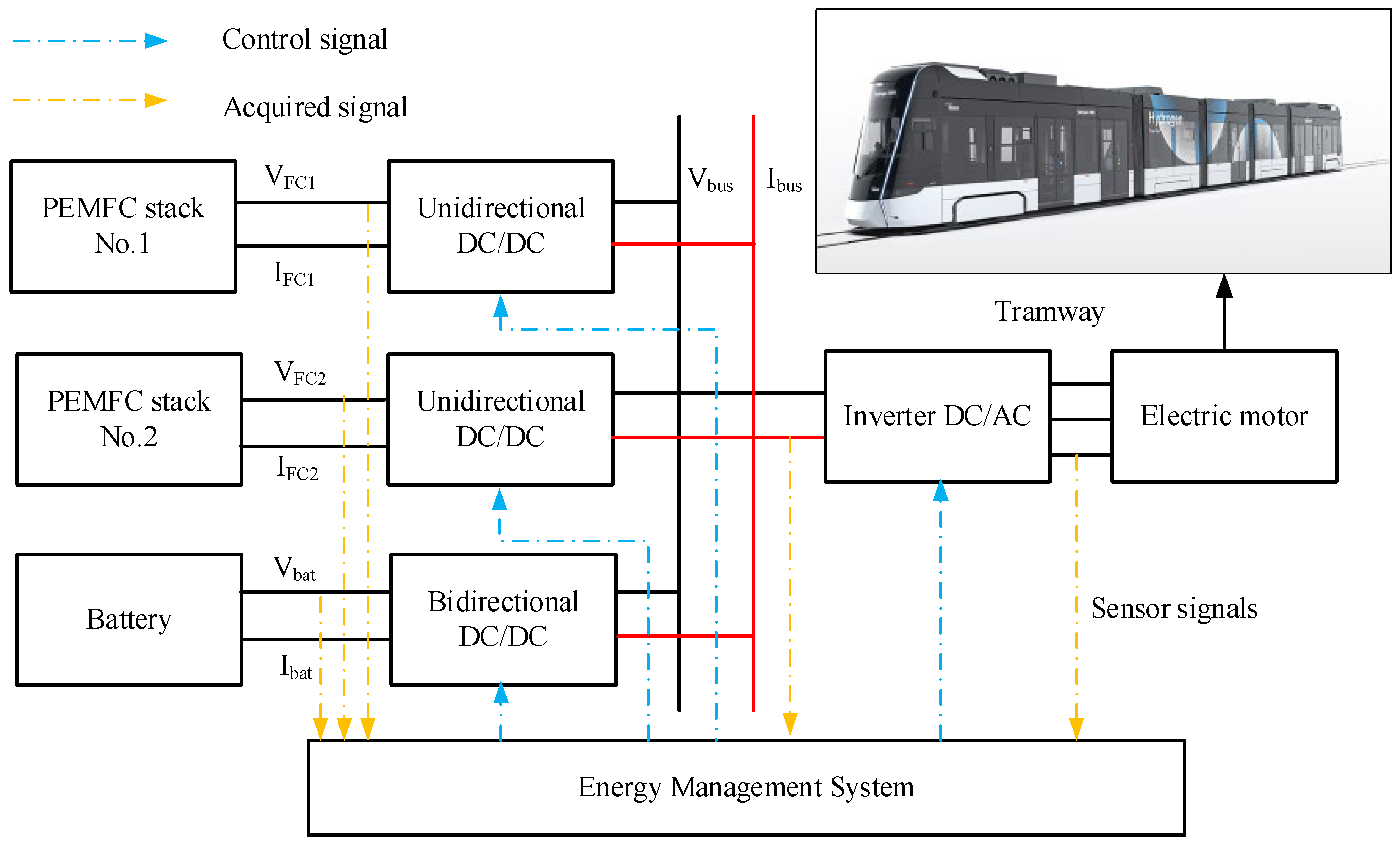
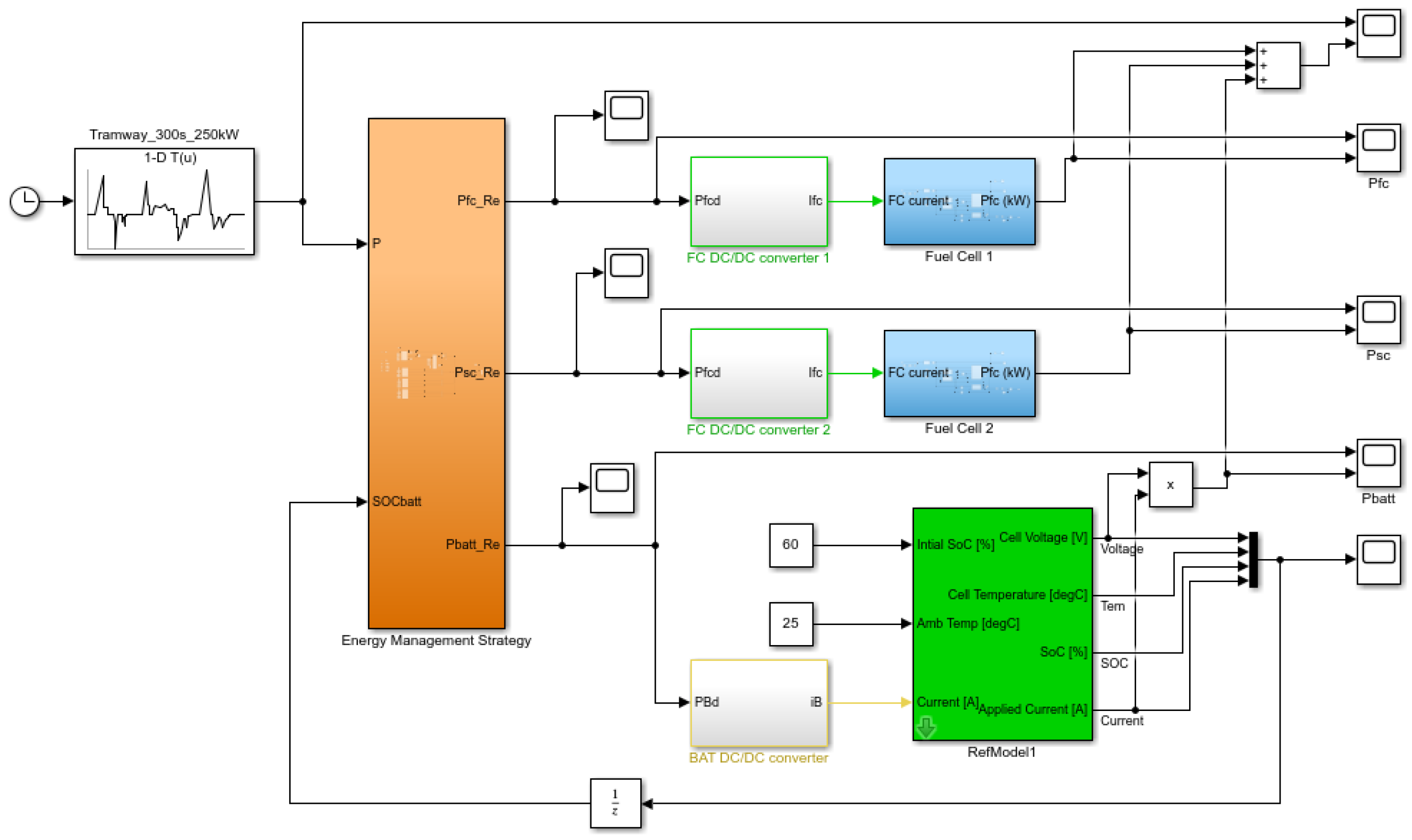
2. Dual-Stack FC/BAT Hybrid Tramway Configuration

2.1. Powertrain Configuration

The configuration of the dual FC/BAT tramway was designed based on a hybrid LF-LRV tramway which is being developed by Chinese manufacturers from Tangshan Railway Vehicle Co. Ltd. and Southwest Jiaotong University, as shown in Figure 1 [18,19,20]. The proposed dual FC/BAT hybrid tramway configuration includes two PEMFC systems which are connected with two unidirectional DC/DC converters and a BAT connected with a bidirectional DC/DC converter. During operation, the dual FC systems function as the primary power source, supplying the power to the DC bus. The output voltage of the FC systems is boosted to the required voltage of the DC bus via unidirectional DC/DC converters working in boost mode. In addition, excess power is charged or discharged to the BAT through the bidirectional DC/DC converter by changing the buck mode and boost mode, respectively. The DC bus is connected to a DC/AC inverter and supplies the electrical power to the electric motor. To efficiently allocate the power requirement from the electric motor to each power source, we built a mathematical model of each component in the powertrain to mimic the dynamic behavior. Then, we designed and validated the energy management strategy based on the model developed to satisfy the power requirement of the hybrid tramway, as shown in Figure 2.

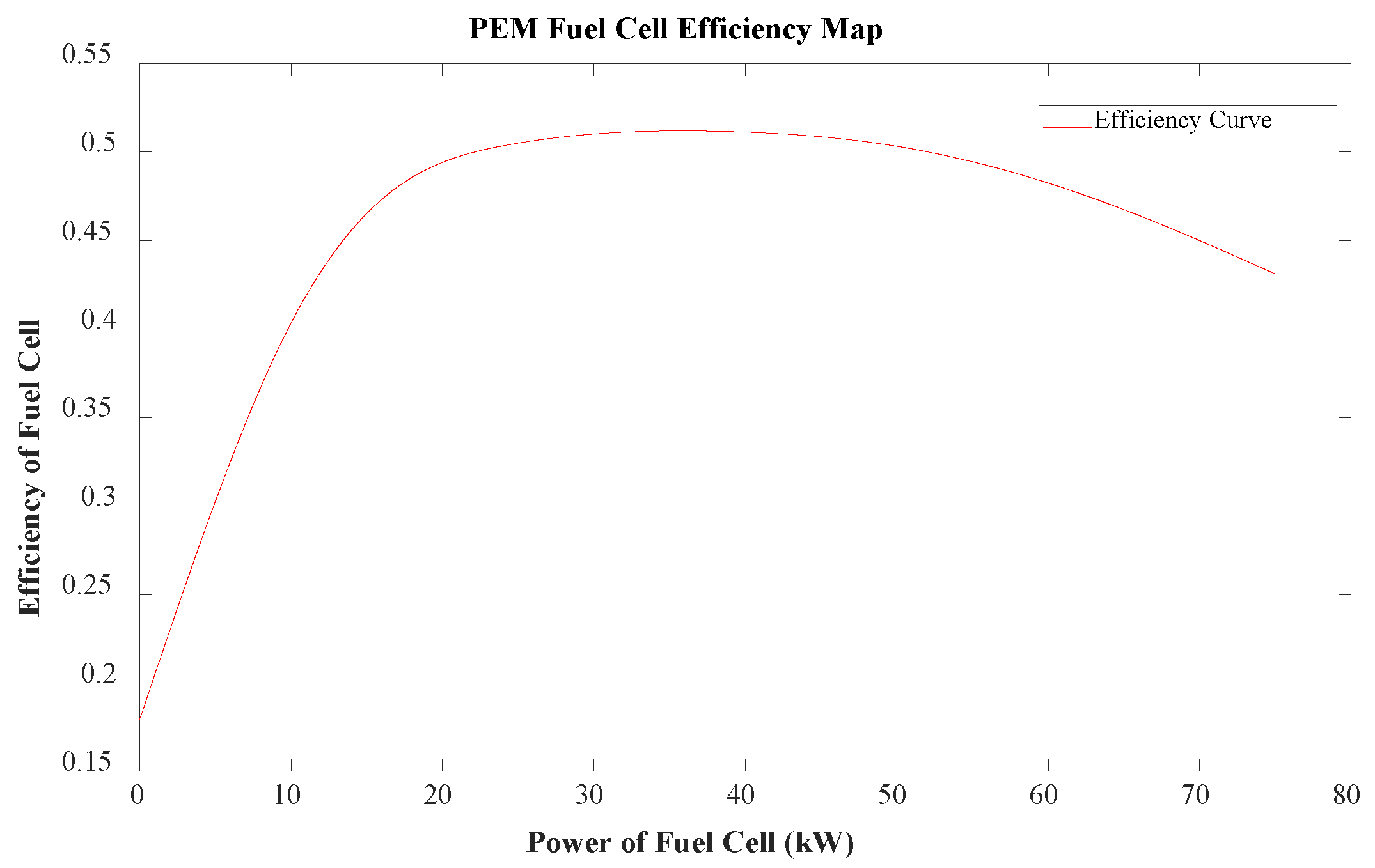
2.2. Fuel Cell Model

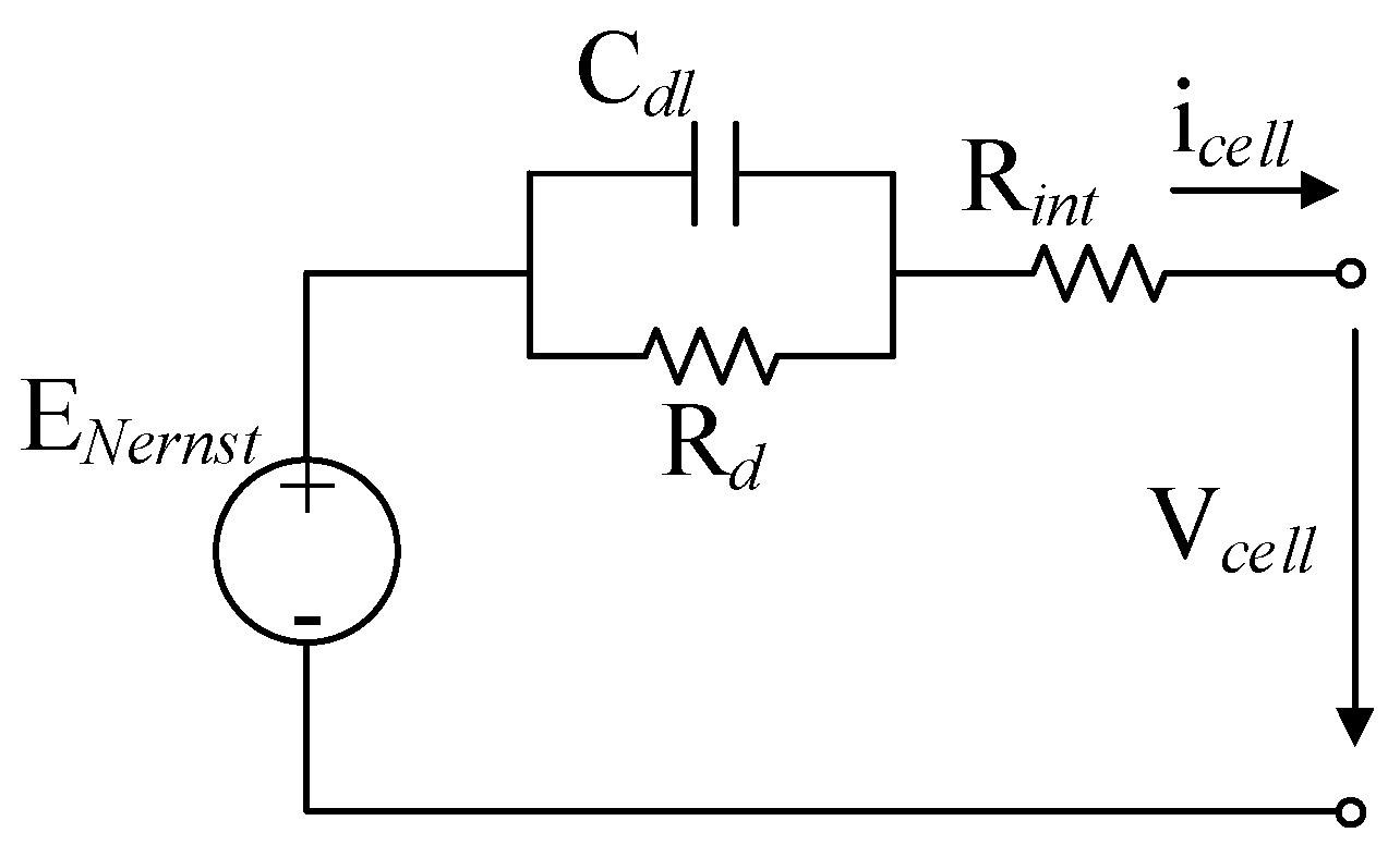
2.2.1. Electrochemical Model

A simplified model of the FC is shown in Figure 3, the output voltage of which can be defined as follows [21,22]:
V c e l l = E N e r n s t V a c t V c o n c V o h m i c
where the following symbols represent different parameters in this model: E N e r n s t is the thermodynamic potential, V a c t represents the activation voltage loss, V c o n c denotes the concentration voltage loss, and V o h m i c refers to the ohmic voltage loss.
The Nernst equation for reversible thermodynamic potential is presented as follows:
E N e r n s t = 1.229 8.5 × 10 4 ( T 298.15 )   + R T 2 F ln p H 2 ( p O 2 ) 0.5
where p H 2 , p O 2 denote the hydrogen and oxygen partial pressure, T represents the cell temperature, R is the universal gas constant, and F is the Faraday constant.
Additionally, the ohmic voltage loss resulting from the internal resistance of the electrolyte membrane is estimated using the following equation:
V o h m i c = i R i n t
The activation voltage loss, which is accountable for the primary decrease in fuel cell voltage at low current densities, can be characterized as
V a c t = ξ 1 + ξ 2 T + ξ 3 T ln c O 2 + ξ 4 T ln i
where i is the cell current, and R int , c O 2 , and ξ 1 ... ξ 4 are the internal resistance of the electrolyte membrane, the oxygen concentration at the cathode/membrane interface, and the parametric coefficients, respectively.
The reactant concentration change during the electrochemical reaction at the electrode surface can be estimated as
V c o n c = R T n F ln i / A L i / A L i / A
Due to the double capacitor layers effect, the voltage drop, V d , at the electrode–electrolyte interface can be calculated as [23]
d V d d t = i C d l V d R d C d l
where R d indicates the sum of activation resistance and concentration resistance.
R d = V a c t + V c o n c i
Based on all of the aforementioned effects, the voltage output of a single cell can be estimated as
V c e l l = E N e r n s t V d V o h m i c
The total voltage generated by N cells can be estimated as follows:
V s t a c k = N V c e l l

2.2.2. Reactant Flow Model

The reactant flow model for the anode is given by the following equation:
V a R T d p H 2 d t = m ˙ H 2 , i n m ˙ H 2 , o u t N i 2 F
where V a ,     m ˙ H 2 , i n ,     m ˙ H 2 , o u t are the anode volume, hydrogen inlet, and hydrogen outlet flow rates through the FC stack, respectively.
The hydrogen outlet flow rate through the FC stack is given by:
m ˙ H 2 , o u t = k a p H 2 p tan k
where ka is a flow constant for the anode, and p tan n k is the pressure of the hydrogen tank.
Similar to the cathode, we obtain:
V c R T d p O 2 d t = m ˙ O 2 , i n m ˙ O 2 , o u t N i 4 F
where V c ,     m ˙ O 2 , i n ,     m ˙ O 2 , o u t are the cathode volume, oxygen inlet, and oxygen outlet flow rates through the FC stack, respectively.
m ˙ O 2 , o u t = k c p O 2 p B P R
The total power input of the system is proportional to the amount of hydrogen consumed.
P t o t = m ˙ H 2 , u s e d Δ H = N i 2 F Δ H
where Δ H is the enthalpy of combustion for hydrogen.
Finally, the output power, PFC, is obtained as
P F C = V s t a c k i
From the output power of each FC, the power output of the dual fuel cell can be calculated as
P d u a l   f u e l   c e l l = P F C , s ys 1 + P F C , s ys 2
where P F C , s ys 1 and P F C , s ys 2 are the output powers of FC 1 and FC 2, respectively. From the power of each system, the hydrogen consumption, m ˙ d u a l   f u e l   c e l l , can be calculated as [24]
m ˙ d u a l   f u e l   c e l l = P F C , s ys 1 η F C , s ys 1 L H V + P F C , s ys 2 η F C , s ys 2 L H V
where η F C , s ys 1 and η F C , s ys 2 represent the efficiencies of FC 1 and FC 2, respectively (as shown in Figure 4). LHV is a lower heating value. The average efficiency of the dual FC system can be estimated as follows:
η d u a l   F u e l   C e l l = P 1 η F C , s ys 1 + P 2 η F C , s ys 2 P 1 + P 2

2.3. Battery Model

The BAT is considered to be another second unit that acts as the buffer supply for the system when the FC cannot adapt to the power demand during endurance operation. To design an EMS, it is necessary to build a BAT model with some referenced parameters to evaluate the working state, thereby providing criteria for an effective EMS design. The model of the BAT is shown in [25,26]. In this study, the BAT is simply taken for the purpose of the EMS design as follows:
The controlled voltage source is presented as [27].
E = E 0 K Q max Q + A e B Q Q max
The BAT voltage is estimated as
V b a t = E R i
where Qmax, A, B, and R are the maximum capacity, exponential voltage, exponential capacity, and resistor of the BAT, respectively. E0 is the voltage of the no-load condition, and K represents the polarized voltage constant.
The BAT voltage related to the BAT state of charge (SOCbat) can be rewritten as [28]
E = E 0 K 1 S O C b a t + A e B Q max S O C b a t 1
During the discharge process, the energy released from the BAT is estimated as
E r e l e a s e = E 0 K 1 S O C b a t × i t R i + A e B Q max S O C b a t 1 K 1 S O C b a t × i *
where i* denotes the filtered current at low frequency, and t denotes the time parameterized. The output power of the BAT is calculated as
P b a t = V b a t i
Then, SOCbat can be derived from the charging current and its maximum charge of it.
S O C = Q max i t Q max
The capacity loss model can be used to estimate BAT degradation as follows:
Q l oss σ , A h = σ I c , θ , S O C A h z
where Ah is the accumulated charge throughput, z is the power law exponent that represents Ah throughput dependence, z = 0.52 , Ic is the charging current, θ is the test temperature, and σ is a nonlinear function of severity factors, which can be expressed as
σ = A b a t S O C + B b a t exp E a + η I c R g 273.15 + θ
where Abat, Bbat, and η are determined using the curve fitting method; η = 63.54 ; A b a t = 74.99 ; B b a t = 12895.92 ; Rg is the universal gas constant, which equals 8.314 J/mol/K; and Ea is the activation energy, which equals 31,700 J/mol [29]. The accumulated charge throughput, Ah, which can be seen as the BAT capacity loss, is estimated as
A h = 0 t σ I c t d t
Then, the State of Health (SoH) can be calculated as follows:
S O H t = Q b a t , n o m Q l oss t Q b a t , n o m
where Q b a t , n o m is the nominal capacity of the BAT.

2.4. DC/DC Converter Model

In this system, two DC/DC boost converters are used to connect with the PEM FC system and convert electrical power between the low-voltage side and the high-voltage side. Meanwhile, a bidirectional DC/DC converter is placed between the BAT and the DC bus for both the distribution and regeneration cycles. As power management operates in a higher layer than local control, and different layers need to be dealt with at different operating frequencies, it is necessary to assume that the time constant of the inductor is significantly greater than the switching cycles. The high conversion rate of the DC/DC converter and the modulation frequency make it possible to use an average model [30,31]. Moreover, once the inner loop sub-system is well-controlled, it should respond promptly to the reference. Therefore, it is necessary to reduce the fast dynamics of the DC/DC converter via the following equivalent static model [32]:
V I V h = L d i L d t + i L R L
V h = κ V O
i O = κ i L η β β = 1 ,                 for   boost   converter   or   for                                         bidirectional   converter   with   i O V O 0 β = 1 ,           for   bidirectional   converter   with   i O V O < 0
where VI, is the input, while VO is the output voltage at the DC/DC converter. L denotes the inductance, RL is the resistor of the inductor, κ denotes the ratio of the converter, and iL, and iO represent the input current and output current, respectively. η represents the converter’s efficiency.

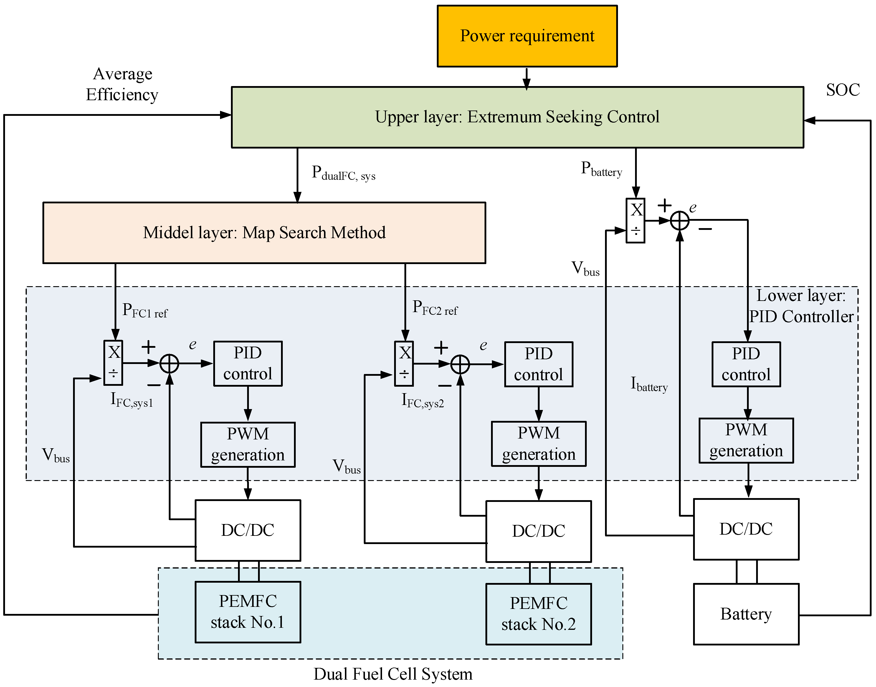
3. Proposed Energy Management Strategy

The main purpose of this energy management strategy is to optimize the power distribution between power sources whilst satisfying the power requirement from the tramway’s powertrain and constraints. The proposed energy management strategy is shown in Figure 5, which contains three layers: the upper layer, middle layer, and lower layer. The upper layer is used to distribute the required power to the dual FC system and BAT by using the extremum-seeking control. Then, the reference power of the dual FC system is distributed to FC 1 and FC 2 by using the MSM in the middle layer. Finally, the lower layer is integrated to control the DC/DC converter, which can adjust the output power of the FC and BAT to track the reference signal.

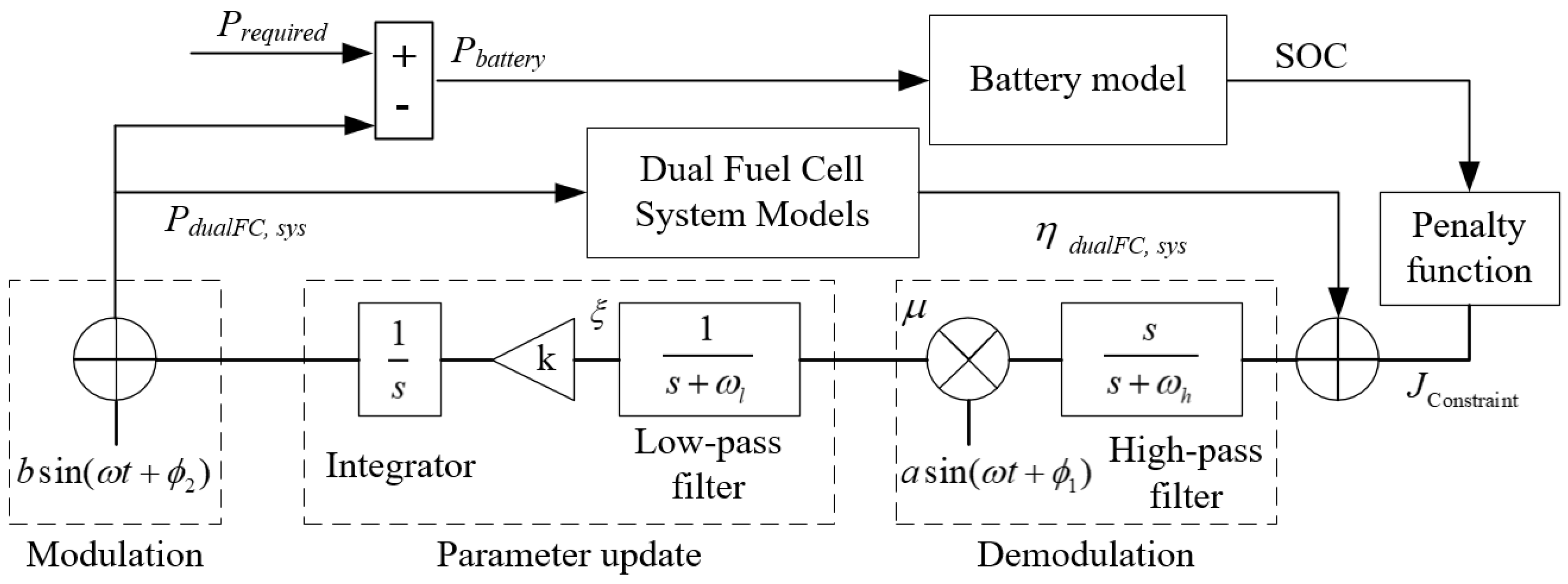
3.1. Upper Layer: Band-Pass Filter Extremum-Seeking Control

The required power must be distributed efficiently between the dual FC system and the electric motor/generator. Given the complexity of the target system, a real-time, model-free energy management strategy would be a more suitable candidate. Based on this observation, we employed the BFESC to optimize the energy flows of the system, as described in this section. The structure of the proposed BFESC, which uses both a high-pass filter and a low-pass filter in the controller scheme, is presented in Figure 6. The power requirement is distributed to the BAT and dual FC system. The equation of this method is shown below.
μ = a sin ω t + ϕ 1 J Constraint + η dual   fuel   cell L 1 s s + ω h ξ = μ L 1 1 s + ω l P d u a l   f u e l   c e l l = b sin ω t + ϕ 2 + ξ L 1 k s P required = P d u a l   f u e l   c e l l + P b a t t e r y
where Prequired, Pdual fuel cell, and Pbattery are the power requirement, the power of the dual FC, and the power of the BAT, respectively. μ is the output of demodulation, and ξ is the output of the low-pass filter. L 1 represents the inverse Laplace transform, and the notation “ ” denotes the convolution operation. η Fuelcell is the efficiency of the dual FC system.
Unlike previous research [2,16], which only considers the battery’s SOC, this paper proposes a penalty function to ensure the safety of the BAT by considering not only the SOC but also the current as input parameters. The penalty function is designed as shown in Equation (33). When the BAT’s parameters exceed the desired ranges, the signal from the penalty function acts as a virtual disturbance that opposes the dual FC’s efficiency.
J Constraint = x = S O C , I c , T k x m a x k 1 x x min x x min , 0 , k 2 x x x m a x x m a x 2 with   k 1 S O C , k 2 S O C = 1 , 1 k 1 I c , k 2 I c = 1 , 1
where k x denotes penalty gains which are turned and fixed during the operation, xmin and xmax represent the design boundaries.

3.2. Middle Layer: Map Search Method

In this layer, the calculated power requirement of the dual FC system should be distributed to each FC by using an efficient energy allocation strategy to improve the performance of the dual PEMFC system and reduce hydrogen consumption. From Equation (17), it can be seen that maximizing the efficiency of the dual FC system can minimize the level of energy consumption. Considering the efficiency maps of two FC systems that assume similar curves, as shown in Figure 4, required power values from 0 to 150 kW are tested (assuming that the maximum power of a dual FC system is 150 kW). Then, the power output of each FC system is run from 0 to 75 kW. With each required power value, the MSM is used to determine a combination of the power of FC 1 and FC 2 based on the efficiency maps to make sure that this combination can satisfy the required power (Equation (16)) and guarantee the maximum value of the efficiencies (Equation (17)). Consequently, the power allocation curves of FC 1 and FC 2 are defined according to the power requirement (Figure 7), and the average efficiency of the dual FC system is also determined (Figure 8), which can be used for the upper layer in Equation (32).

3.3. Lower Layer: PID Controller

The reference power can be given from the upper layer and middle layer, as presented above. The error between the measured current of each device and the reference current is transferred to the PID controller. The output signals of the PID controllers are given to PWM generations to be converted to PWM signals. These signals are used to control the DC/DC converters to achieve the power requirement (Figure 9).

4. Simulation and Discussion

To fully evaluate the effectiveness of the proposed hierarchical control strategy presented in Section 3, the performance of the hybrid power source supply to the hydrogen tramway was investigated via the simulation method. The simulation models and proposed control strategies were conducted in MATLAB 2021a, as presented in Figure 10. The key parameters of the PEMFC and BAT are listed in Table 1 and Table 2, in which the PEMFC parameters were taken from Ballard’s Fuel Cell [33] and the battery model was built based on the configuration of a Nissan Leaf Lithium Ion battery [34]. First, a comparison between the proposed BFESC-MSM, non-constraint ESC-MSM (NCESC-MSM), and rule-based strategy (RBS) [10] was conducted in the case of a high current condition based on the power requirement of the hydrogen tramway (Figure 4). Second, a scenario with a high current and SOC was used to prove the effectiveness of the proposed EMS.

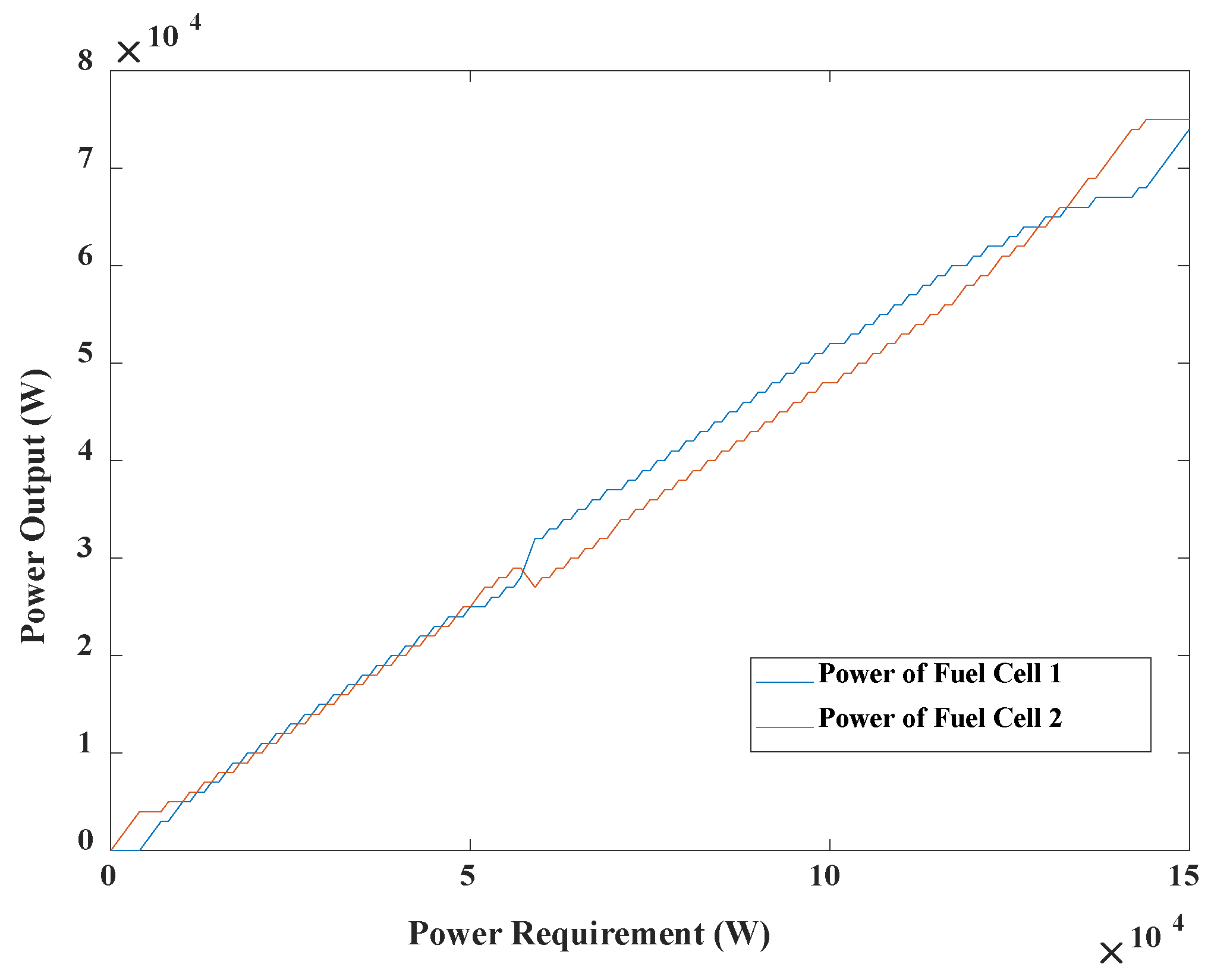
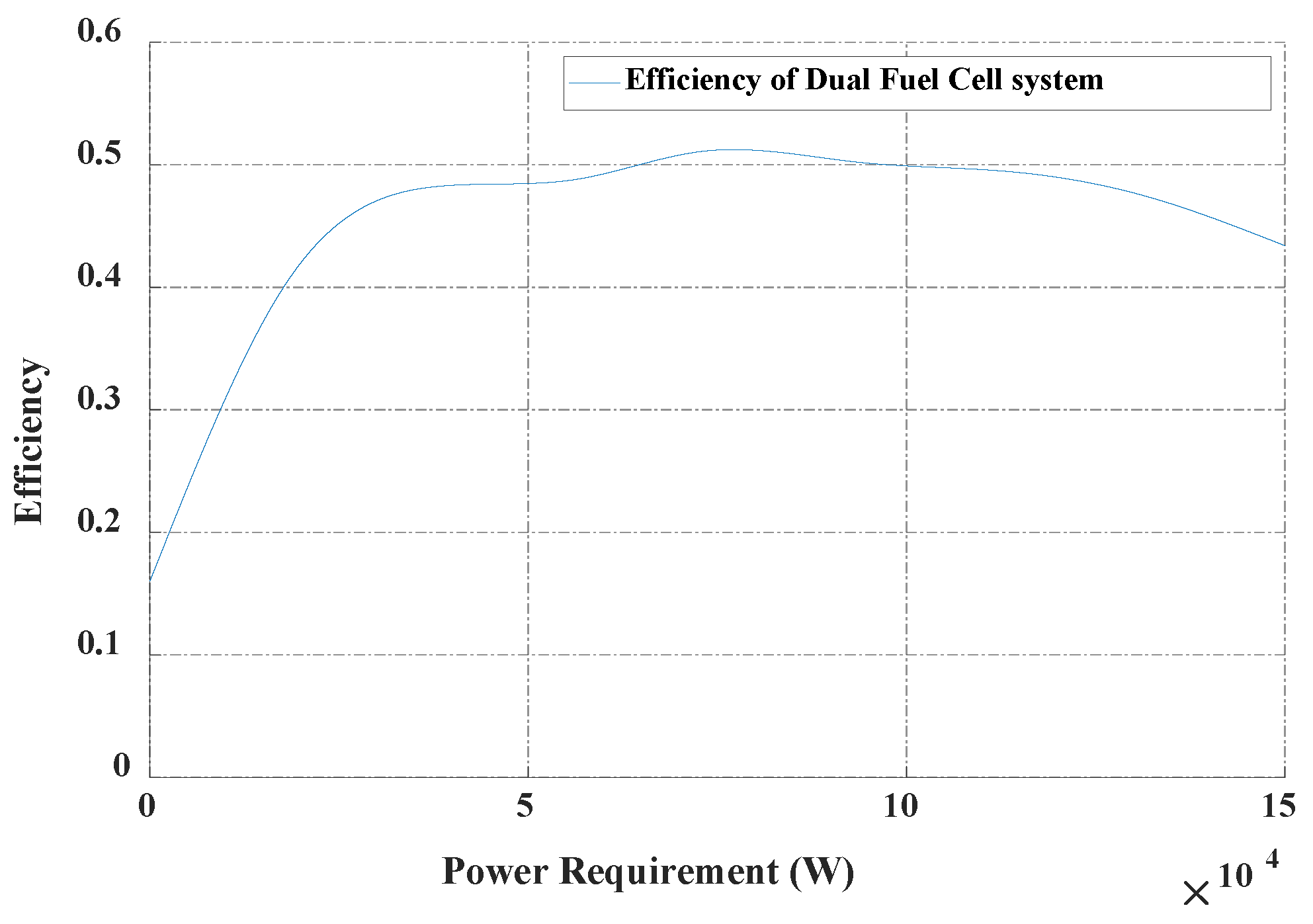
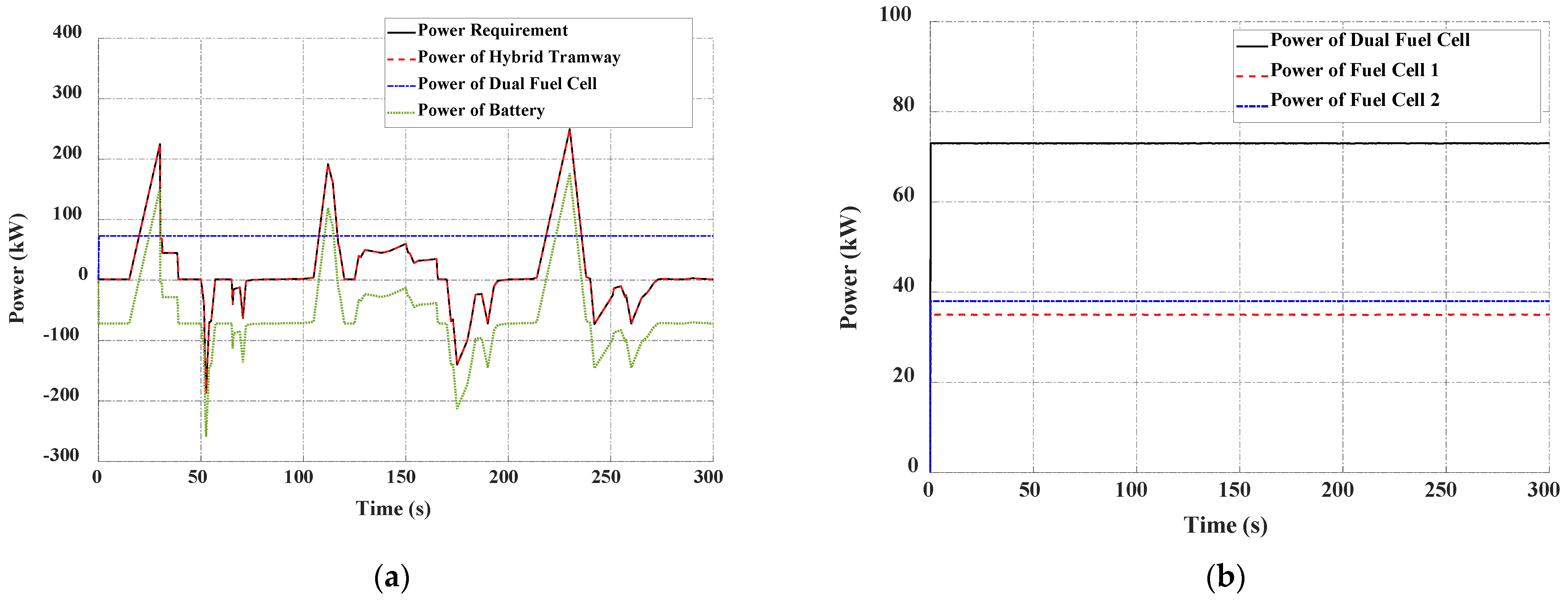
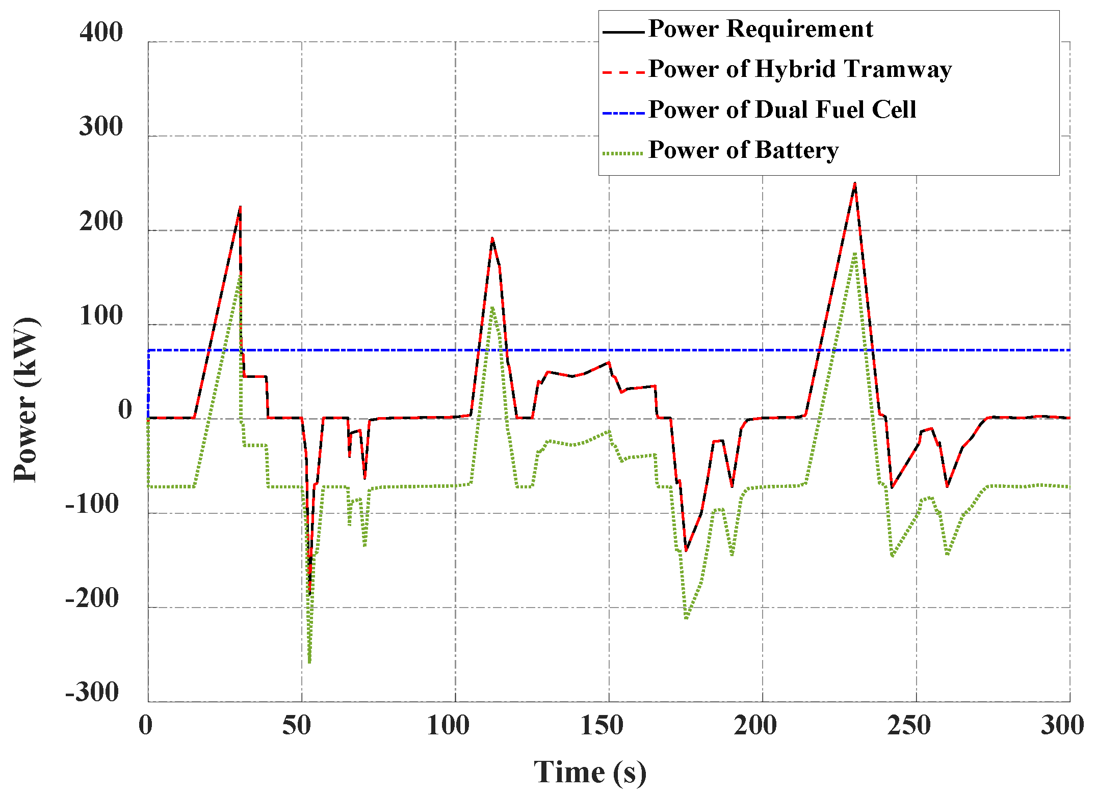
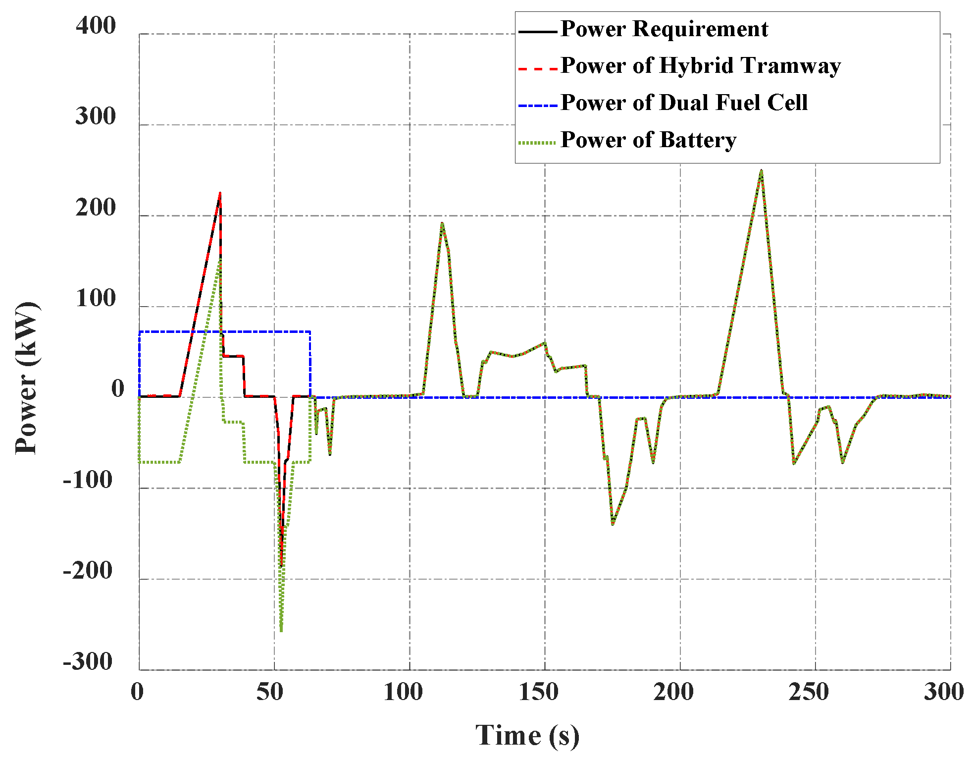
4.1. Case Study 1: High Current

The first simulation was performed using a high current operation condition with a battery with the working boundary of the current in the range from −65 A to 65 A. In addition, the initial SOC of the battery was set at 60%. The simulation results indicated that the power requirement of the hydrogen tramway was distributed to each power source by using the proposed BFESC-MSM. In this strategy, the upper layer allocated the power requirement to the dual fuel cell and battery, while the middle layer distributed the power reference of the dual fuel cell to each fuel cell system, as shown in Figure 11. Considering the battery status, the power reference of the dual fuel cell was changed to guarantee the current of the battery worked within the desired ranges. This led to the fuel cell’s efficiency not being maintained at the highest working point. Meanwhile, in the NCESC-MSM, the power of the dual fuel cell was maintained at a constant value at the highest working point (Figure 12). The power distribution using the RBS was similar to that using NCESC-MSM, and the dual fuel cell also maintained its highest efficiency value without examining the battery status (Figure 13). Therefore, the NCEMS-MSM and RBS achieved higher fuel cell efficiency, as depicted in Figure 14. However, these EMSs could not maintain the current in the desired range, leading to an increase in battery losses (Figure 15 and Figure 16). With the proposed EMS, the current of the battery was limited to the boundary, enhancing the battery’s durability. Compared with the ESC without constraints, the capacity loss of the battery using the proposed EMS could be appropriately reduced by 16.67%.

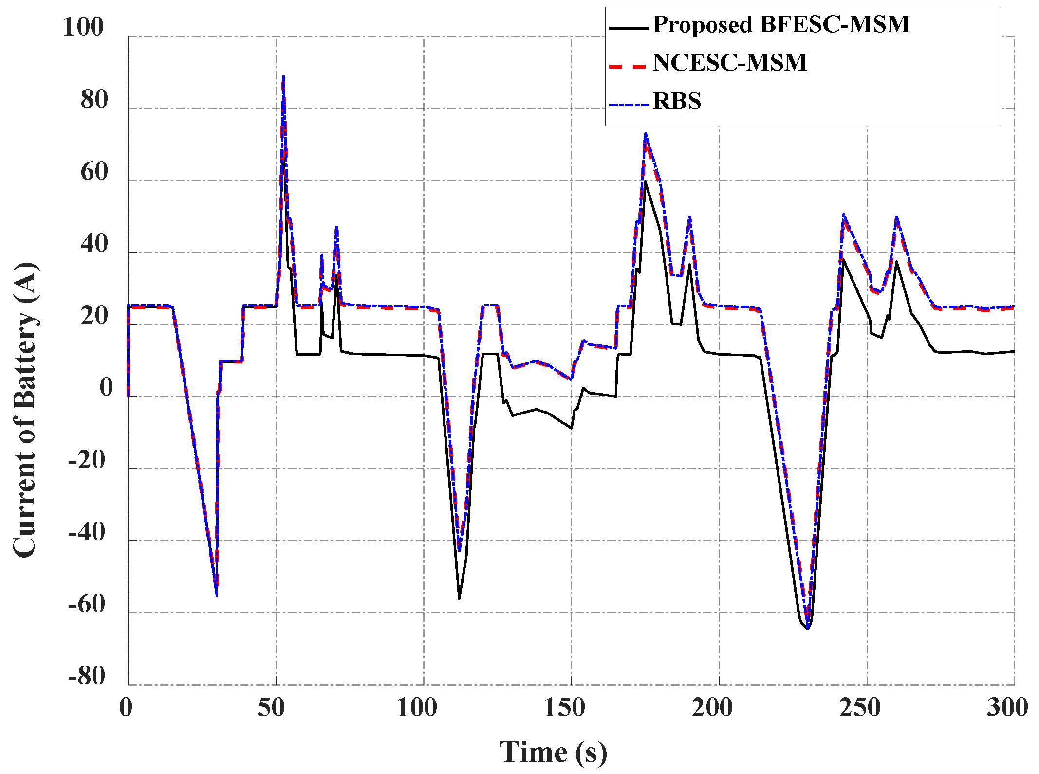
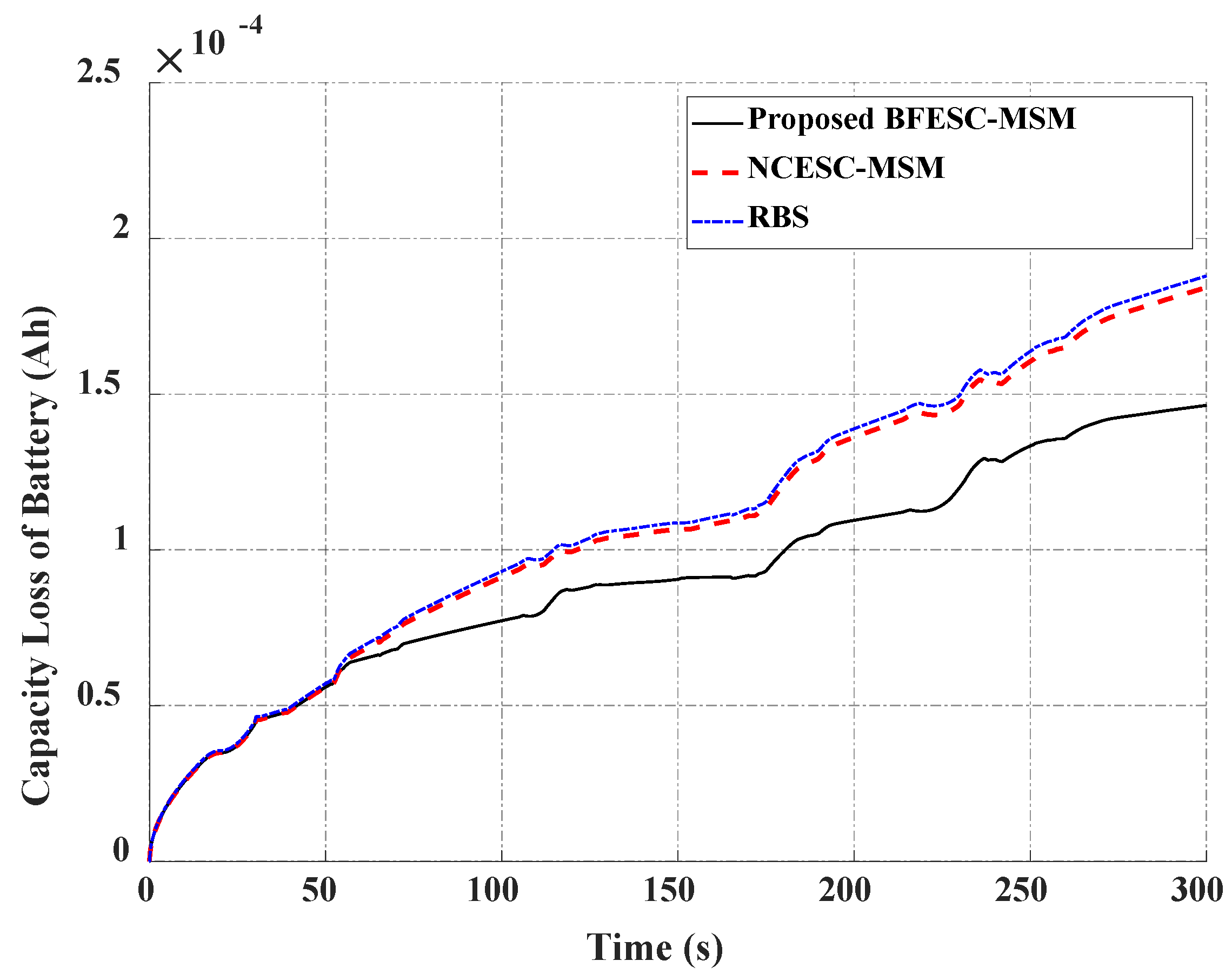
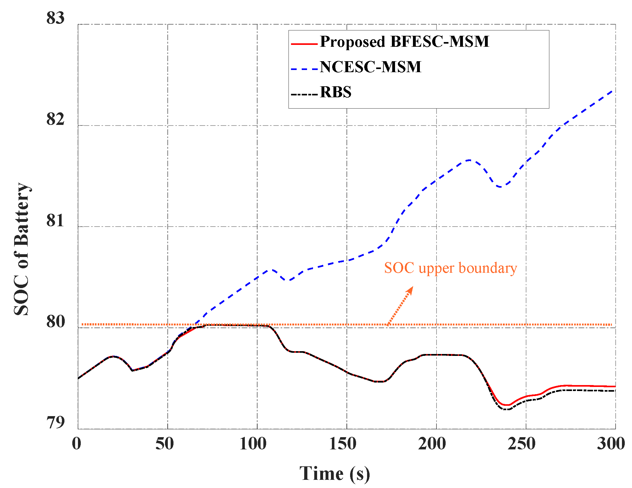
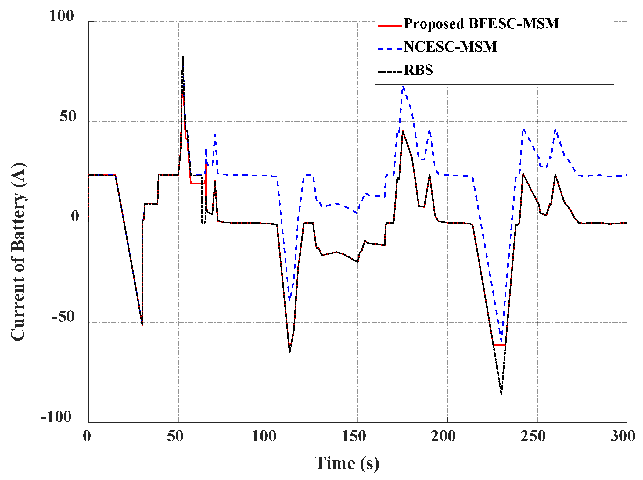
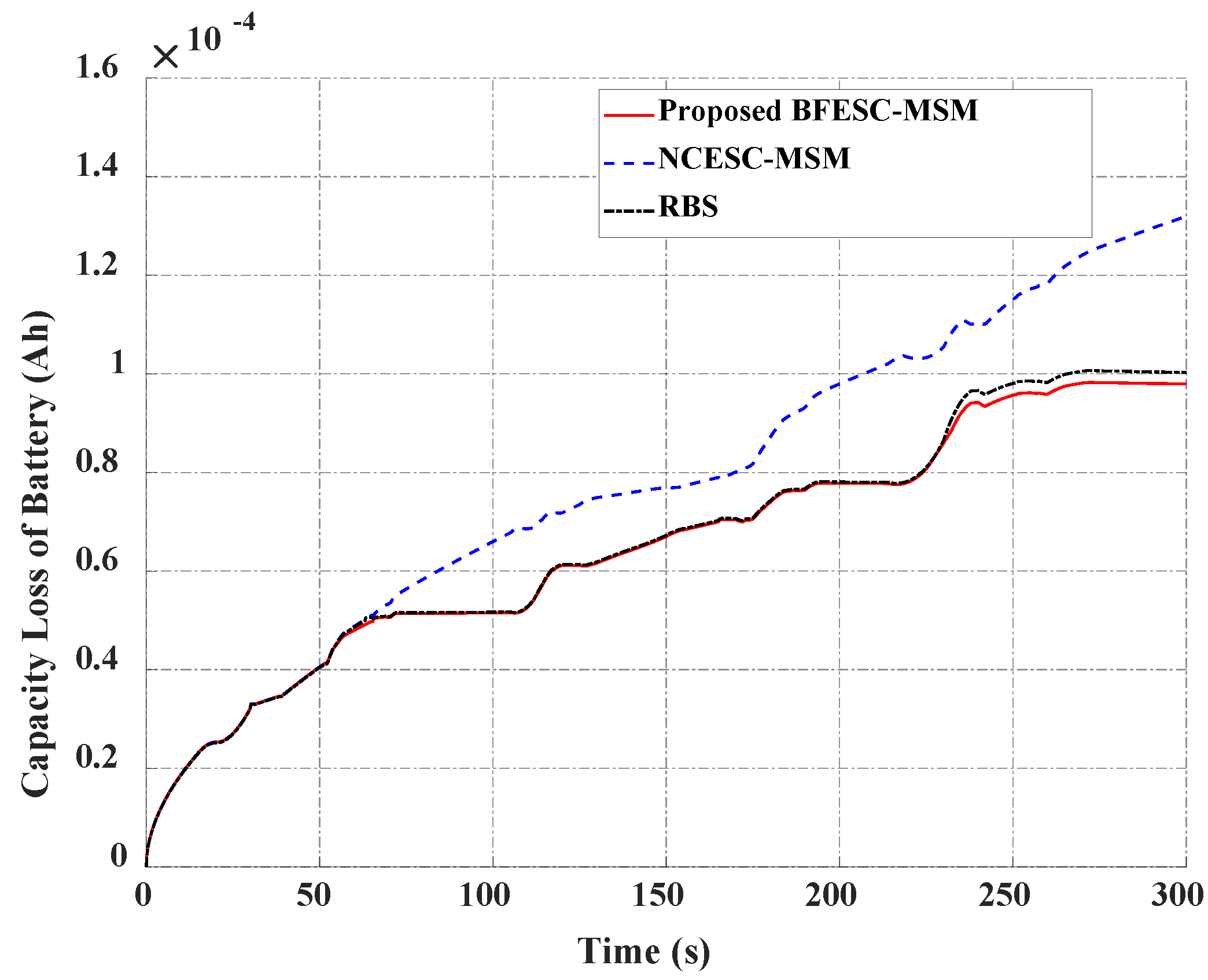
4.2. Case Study 2: High Current and High SOC

The second simulation was conducted under a condition in which the battery had a high SOC, in which the initial SOC was set at 79.5%. Using the EMSs, the hydrogen tramway’s power was distributed to each power source. By considering the constraints of the battery SOC, the power of the dual fuel cell was changed and used as a supplementary power to compensate for the battery when the SOC of the BAT reached its upper boundary. Then, the power requirement was mainly supplied by the battery, as shown in Figure 17. Meanwhile, without considering the battery status, the NCESC-MSM and RBS continued to keep the dual fuel cell working in the high-efficiency region, as plotted in Figure 18 and Figure 19. In addition, the power reference of the dual fuel cell was also changed when the SOC of the BAT reached its maximum value (Figure 20). The maximum current of the BAT was not included in the constraints of the RBS. Therefore, this resulted in the SOC and current of the battery exceeding the desired upper boundary (80%) and reducing the battery life (Figure 21 and Figure 22). The capacity loss of the battery indicated that using the proposed EMS could improve the capacity loss by 25.9% compared with the NCESC-MSM and by about 2% compared with the RBS, as shown in Figure 22.

5. Conclusions

In this paper, a novel energy management system based on a combination of online and offline optimization methods was designed to effectively distribute power from the load demand to each component to keep the system working in a highly efficient region and improve the battery lifetime. Specifically, the online BFESC was used in the upper layer to optimally distribute the power between the dual fuel cell and battery. In addition, the offline method, called the MSM, was designed based on fuel cell efficiency maps to allocate the dual fuel cell’s power reference to each fuel cell system. The effectiveness of the proposed EMS was demonstrated through a simulation model we developed. The simulation results of two case studies showed that the system can satisfy the load. In terms of the battery status, using the proposed EMS, the efficiency of the fuel cell was lower than 4% compared with the NCESC-MSM and the RBS. However, the capacity loss of the battery could improve by up to 25.9% in the case of a high current and high SOC. However, in a hybrid power source, both the battery and fuel cell have short lifespans and sensitivity to sudden changes. Therefore, in future work, fuel cell degradation will be considered in the designed EMS to improve its lifetime.

Author Contributions

T.-C.D. carried out the investigation and methodology, built and validated the model and the proposed algorithm through MATLAB simulations, carried out the experiment setup, and wrote the original manuscript. H.-A.T. supported the experiment setup and checked the manuscript. K.-K.A. was the supervisor providing funding and administrating the project, and they reviewed and edited the manuscript. All authors have read and agreed to the published version of the manuscript.

Funding

This research was financially supported by the “Hydrogen Electric Tram Demonstration Project” through the Ministry of Trade, Industry & Energy (MOTIE) and Korea Institute for Advancement of Technology (KIAT), and this work was supported by “Regional Innovation Strategy (RIS)” through the National Research Foundation of Korea (NRF), funded by the Ministry of Education (MOE) (2021RIS-003).

Data Availability Statement

Not applicable.

Conflicts of Interest

The authors declare no conflict of interest.

References

  1. Do, T.C.; Truong, H.V.A.; Dao, H.V.; Ho, C.M.; To, X.D.; Dang, T.D.; Ahn, K.K. Energy Management Strategy of a PEM Fuel Cell Excavator with a Supercapacitor/Battery Hybrid Power Source. Energies 2019, 12, 4362. [Google Scholar] [CrossRef]
  2. Truong, H.V.A.; Dao, H.V.; Do, T.C.; Ho, C.M.; To, X.D.; Dang, T.D.; Ahn, K.K. Mapping Fuzzy Energy Management Strategy for PEM Fuel Cell–Battery–Supercapacitor Hybrid Excavator. Energies 2020, 13, 3387. [Google Scholar] [CrossRef]
  3. Shang, Z.; Hossain, M.M.; Wycisk, R.; Pintauro, P.N. Poly (phenylene sulfonic acid)-expanded polytetrafluoroethylene composite membrane for low relative humidity operation in hydrogen fuel cells. J. Power Sources 2022, 535, 231375. [Google Scholar] [CrossRef]
  4. Marx, N.; Boulon, L.; Gustin, F.; Hissel, D.; Agbossou, K. A review of multi-stack and modular fuel cell systems: Interests, application areas and on-going research activities. Int. J. Hydrogen Energy 2014, 39, 12101–12111. [Google Scholar] [CrossRef]
  5. Marx, N.; Cardozo, J.; Boulon, L.; Gustin, F.; Hissel, D.; Agbossou, K. Comparison of the series and parallel architectures for hybrid multi-stack fuel cell-battery systems. In Proceedings of the 2015 IEEE Vehicle Power and Propulsion Conference (VPPC), Montreal, QC, Canada, 19–22 October 2015; pp. 1–6. [Google Scholar] [CrossRef]
  6. De Bernardinis, A.; Péra, M.-C.; Garnier, J.; Hissel, D.; Coquery, G.; Kauffmann, J.-M. Fuel cells multi-stack power architectures and experimental validation of 1 kW parallel twin stack PEFC generator based on high frequency magnetic coupling dedicated to on board power unit. Energy Convers. Manag. 2008, 49, 2367–2383. [Google Scholar] [CrossRef]
  7. Han, X.; Li, F.; Zhang, T.; Zhang, T.; Song, K. Economic energy management strategy design and simulation for a dual-stack fuel cell electric vehicle. Int. J. Hydrogen Energy 2017, 42, 11584–11595. [Google Scholar] [CrossRef]
  8. Bahrami, M.; Martin, J.-P.; Maranzana, G.; Pierfederici, S.; Weber, M.; Meibody-Tabar, F.; Zandi, M. Multi-stack lifetime improvement through adapted power electronic architecture in a fuel cell hybrid system. Mathematics 2020, 8, 739. [Google Scholar] [CrossRef]
  9. Zhang, C.; Zeng, T.; Wu, Q.; Deng, C.; Chan, S.H.; Liu, Z. Improved efficiency maximization strategy for vehicular dual-stack fuel cell system considering load state of sub-stacks through predictive soft-loading. Renew. Energy 2021, 179, 929–944. [Google Scholar] [CrossRef]
  10. Wang, T.; Li, Q.; Yin, L.; Chen, W. Hydrogen consumption minimization method based on the online identification for multi-stack PEMFCs system. Int. J. Hydrogen Energy 2019, 44, 5074–5081. [Google Scholar] [CrossRef]
  11. Macias, A.; Kandidayeni, M.; Boulon, L.; Chaoui, H. A novel online energy management strategy for multi fuel cell systems. In Proceedings of the 2018 IEEE International Conference on Industrial Technology (ICIT), Lyon, France, 16–19 February 2018; pp. 2043–2048. [Google Scholar] [CrossRef]
  12. Fernandez, A.M.; Kandidayeni, M.; Boulon, L.; Chaoui, H. An adaptive state machine based energy management strategy for a multi-stack fuel cell hybrid electric vehicle. IEEE Trans. Veh. Technol. 2019, 69, 220–234. [Google Scholar] [CrossRef]
  13. Tao, S.; Chen, W.; Gan, R.; Li, L.; Zhang, G.; Han, Y.; Li, Q. Energy management strategy based on dynamic programming with durability extension for fuel cell hybrid tramway. Railw. Eng. Sci. 2021, 29, 299–313. [Google Scholar] [CrossRef]
  14. Song, K.; Wang, X.; Li, F.; Sorrentino, M.; Zheng, B. Pontryagin’s minimum principle-based real-time energy management strategy for fuel cell hybrid electric vehicle considering both fuel economy and power source durability. Energy 2020, 205, 118064. [Google Scholar] [CrossRef]
  15. Zhou, D.; Al-Durra, A.; Matraji, I.; Ravey, A.; Gao, F. Online energy management strategy of fuel cell hybrid electric vehicles: A fractional-order extremum seeking method. IEEE Trans. Ind. Electron. 2018, 65, 6787–6799. [Google Scholar] [CrossRef]
  16. Trinh, H.-A.; Truong, H.-V.-A.; Ahn, K.K. Development of fuzzy-adaptive control based energy management strategy for PEM fuel cell hybrid tramway system. Appl. Sci. 2022, 12, 3880. [Google Scholar] [CrossRef]
  17. Wang, T.; Li, Q.; Yin, L.; Chen, W.; Breaz, E.; Gao, F. Hierarchical power allocation method based on online extremum seeking algorithm for dual-pemfc/battery hybrid locomotive. IEEE Trans. Veh. Technol. 2021, 70, 5679–5692. [Google Scholar] [CrossRef]
  18. Li, Q.; Yang, H.; Han, Y.; Li, M.; Chen, W. A state machine strategy based on droop control for an energy management system of PEMFC-battery-supercapacitor hybrid tramway. Int. J. Hydrogen Energy 2016, 41, 16148–16159. [Google Scholar] [CrossRef]
  19. Li, Q.; Wang, T.; Dai, C.; Chen, W.; Ma, L. Power management strategy based on adaptive droop control for a fuel cell-battery-supercapacitor hybrid tramway. IEEE Trans. Veh. Technol. 2017, 67, 5658–5670. [Google Scholar] [CrossRef]
  20. Li, Q.; Chen, W.; Liu, Z.; Li, M.; Ma, L. Development of energy management system based on a power sharing strategy for a fuel cell-battery-supercapacitor hybrid tramway. J. Power Sources 2015, 279, 267–280. [Google Scholar] [CrossRef]
  21. Khan, M.J.; Iqbal, M.T. Modelling and Analysis of Electro-chemical, Thermal, and Reactant Flow Dynamics for a PEM Fuel Cell System. Fuel Cells 2005, 5, 463–475. [Google Scholar] [CrossRef]
  22. Phan, V.D.; Trinh, H.-A.; Ahn, K.K. Finite-Time Command Filtered Control for Oxygen-Excess Ratio of Proton Exchange Membrane Fuel Cell Systems with Prescribed Performance. Mathematics 2023, 11, 914. [Google Scholar] [CrossRef]
  23. Derbeli, M.; Charaabi, A.; Barambones, O.; Napole, C. High-performance tracking for proton exchange membrane fuel cell system PEMFC using model predictive control. Mathematics 2021, 9, 1158. [Google Scholar] [CrossRef]
  24. Bizon, N.; Thounthong, P. Energy efficiency and fuel economy of a fuel cell/renewable energy sources hybrid power system with the load-following control of the fueling regulators. Mathematics 2020, 8, 151. [Google Scholar] [CrossRef]
  25. Ham, H.; Han, K.; Lee, H. Battery System Modeling for a Military Electric Propulsion Vehicle with a Fault Simulation. Energies 2013, 6, 5168–5181. [Google Scholar] [CrossRef]
  26. Sockeel, N.; Shahverdi, M.; Mazzola, M.; Meadows, W. High-fidelity battery model for model predictive control implemented into a plug-in hybrid electric vehicle. Batteries 2017, 3, 13. [Google Scholar] [CrossRef]
  27. Trinh, H.-A.; Phan, V.-D.; Truong, H.-V.-A.; Ahn, K.K. Energy Management Strategy for PEM Fuel Cell Hybrid Power System Considering DC Bus Voltage Regulation. Electronics 2022, 11, 2722. [Google Scholar] [CrossRef]
  28. Martyushev, N.V.; Malozyomov, B.V.; Sorokova, S.N.; Efremenkov, E.A.; Qi, M. Mathematical Modeling of the State of the Battery of Cargo Electric Vehicles. Mathematics 2023, 11, 536. [Google Scholar] [CrossRef]
  29. Wu, J.; Wang, X.; Li, L.; Du, Y. Hierarchical control strategy with battery aging consideration for hybrid electric vehicle regenerative braking control. Energy 2018, 145, 301–312. [Google Scholar] [CrossRef]
  30. Castaings, A.; Lhomme, W.; Trigui, R.; Bouscayrol, A. Practical control schemes of a battery/supercapacitor system for electric vehicle. IET Electr. Syst. Transp. 2016, 6, 20–26. [Google Scholar] [CrossRef]
  31. Trinh, H.-A.; Nguyen, D.G.; Phan, V.-D.; Duong, T.-Q.; Truong, H.-V.-A.; Choi, S.-J.; Ahn, K.K. Robust Adaptive Control Strategy for a Bidirectional DC-DC Converter Based on Extremum Seeking and Sliding Mode Control. Sensors 2023, 23, 457. [Google Scholar] [CrossRef]
  32. Nguyen, B.; German, R.; Trovão, J.P.F.; Bouscayrol, A. Real-Time Energy Management of Battery/Supercapacitor Electric Vehicles Based on an Adaptation of Pontryagin’s Minimum Principle. IEEE Trans. Veh. Technol. 2019, 68, 203–212. [Google Scholar] [CrossRef]
  33. Ballard. Ballard’s FC Move-HD. Available online: https://www.ballard.com/about-ballard/publication_library/product-specification-sheets/fcmovetm-spec-sheet (accessed on 2 May 2023).
  34. Nissan. 2018 Nissan Leaf Battery Real Specs. Available online: https://pushevs.com/2018/01/29/2018-nissan-leaf-battery-real-specs/ (accessed on 2 May 2023).
Figure 1. Configuration of dual PEM FC/BAT tramway.
Mathematics 11 02269 g001
Figure 2. Power requirement of hybrid LF-LRV tramway.
Mathematics 11 02269 g002
Figure 3. A simplified model of the FC.
Mathematics 11 02269 g003
Figure 4. Efficiency map of FC systems.
Mathematics 11 02269 g004
Figure 5. Flow chart of energy management strategy.
Mathematics 11 02269 g005
Figure 6. Upper layer: BFESC for dual FC/BAT system.
Mathematics 11 02269 g006
Figure 7. Power output allocation using the MSM method.
Mathematics 11 02269 g007
Figure 8. Average efficiency of the dual FC system.
Mathematics 11 02269 g008
Figure 9. Lower layer with PID controller.
Mathematics 11 02269 g009
Figure 10. Dual FC-BAT tramway with mathematical model in MATLAB/Simulink.
Mathematics 11 02269 g010
Figure 11. Power distribution using proposed BFESC-MSM with constraint consideration: (a) upper layer; (b) middle layer.
Mathematics 11 02269 g011
Figure 12. Power distribution using NCESC-MSM: (a) upper layer; (b) middle layer.
Mathematics 11 02269 g012
Figure 13. Power distribution using RBS: (a) upper layer; (b) middle layer.
Mathematics 11 02269 g013
Figure 14. Comparison of efficiency of dual fuel cell in case 1.
Mathematics 11 02269 g014
Figure 15. Comparison of current of BAT in case 1.
Mathematics 11 02269 g015
Figure 16. Comparison of capacity loss of battery in case 1.
Mathematics 11 02269 g016
Figure 17. Power distribution using the proposed BFESC-MSM in case study 2.
Mathematics 11 02269 g017
Figure 18. Power distribution using NCESC-MSM in case study 2.
Mathematics 11 02269 g018
Figure 19. Power distribution using RBS in case study 2.
Mathematics 11 02269 g019
Figure 20. Comparison of SOC of battery in case study 2.
Mathematics 11 02269 g020
Figure 21. Comparison of current of battery in case study 2.
Mathematics 11 02269 g021
Figure 22. Comparison of capacity loss of battery in case study 2.
Mathematics 11 02269 g022
Table 1. Fuel cell system parameters.
ParameterValueUnit
Number of cells380
Rated power75kW
Nominal efficiency58%
Membrane thickness178μm
Anode pressure3atm
Cathode pressure3atm
Cell area232cm2
Table 2. Battery parameters.
ParameterValueUnit
Capacity54Ah
Cell voltage limit2.5–4.2V
Cells in series20Cell
Cells in parallel35Cell
Disclaimer/Publisher’s Note: The statements, opinions and data contained in all publications are solely those of the individual author(s) and contributor(s) and not of MDPI and/or the editor(s). MDPI and/or the editor(s) disclaim responsibility for any injury to people or property resulting from any ideas, methods, instructions or products referred to in the content.

