Article

A Method for Mathematical Modeling of Hydrodynamic Friction of Plunger Pairs with Consideration of Microgeometry

by
Konstantin Gavrilov
1,*,
Yuriy Rozhdestvenskii
2 and
Ildar Umurzakov
1
1
Department of Wheeled and Tracked Vehicles, Institute of Engineering and Technology, South Ural State University, 76 Prospekt Lenina, 454080 Chelyabinsk, Russia
2
Department of Motor Transport, Institute of Engineering and Technology, South Ural State University, 76 Prospekt Lenina, 454080 Chelyabinsk, Russia
*
Author to whom correspondence should be addressed.
Mathematics 2023, 11(12), 2637; https://doi.org/10.3390/math11122637
Submission received: 16 May 2023 / Revised: 2 June 2023 / Accepted: 7 June 2023 / Published: 9 June 2023

Abstract

:
The fuel injection system heavily relies on the high-pressure fuel pump, which plays a critical role in its overall performance. The fuel pump plunger is subjected to high levels of stress and experiences irregular lubrication during dynamic loads, causing premature wear. In the industrial sector, laser surface micro-texturing has been utilized to reduce friction and enhance anti-wear properties, and its positive impact has been supported by both theoretical and experimental evidence. This article presents a method for determining the hydromechanical characteristics of plunger pairs under conditions of hydrodynamic friction. The microgeometry of friction surfaces was taken into account through the cavitation effect of the lubricating fluid, described by the modified Reynolds equation. Software was developed according to the proposed method. The developed software can be used to analyze the contacting surfaces of plunger pairs and evaluate their tribotechnical characteristics based on the microgeometry parameters of the friction surfaces. The article also discusses the impact of the microgeometry parameters on the quality criteria of the hydromechanical characteristics of the plunger pairs. Computational examples are given for the analysis of contacting surfaces of plunger pairs separated by a lubrication layer. The technical characteristics are evaluated depending on the parameters of the microgeometry of the roughness of the friction surfaces. The influence of the microgeometry parameters on the quality criteria of the hydromechanical characteristics of the plunger pairs is presented.

1. Introduction

Currently, there is a pressing need to improve the quality and performance of high-pressure fuel pumps and enhance environmental emission standards.
Friction reduction is a key issue for mechanical engineering. It is necessary to achieve high efficiency, reliability, economy, and ease of operation. Friction is the main cause of energy loss and mechanical system failures. Globally, friction in an engine is a part of power loss, determining its efficiency, although in piston internal combustion engines (ICE), approximately 30% of energy is spent on overcoming friction losses [1,2].
The second significant factor affecting the efficiency of hydraulic plunger pairs is mechanical damage, such as wear of mating surfaces, sticking, and plunger misalignment [3,4,5].
Common rail (CR) fuel injection systems provide better fuel economy, lower emissions, and higher power and form an integral part of modern engines [6,7]. Pump elements are exposed to high loads due to fuel compression under high pressure. The high-pressure fuel pump (HPP) is one of the most important elements of the CR system, the performance of which directly affects the performance of the whole system [8]. An increase in fuel pressure at the top of the plunger cylinder, combined with regularly varying speeds, requires the accurate lubrication of the plunger pair [9]. An increase in pressure leads to more plunger wear and less lubrication, which negatively affects the efficiency of the fuel system [10,11]. Some authors say that the workflow of the HPP is poorly studied [12].
Most of the current research in this field focuses on one or several parameters of microgeometry, and improving one parameter may lead to the deterioration of others. To achieve the most effective prediction of microgeometry utilization in plunger pairs, a mass conservation algorithm was employed in conjunction with the search for optimal microgeometric parameters.
In recent years, the use of textured surfaces to reduce friction and improve the anti-wear properties of tribological couplings has been gaining popularity [13,14,15]. Laser surface texturing is widely used in the industry, and its positive effects have been theoretically predicted and experimentally confirmed [16,17,18].
Laser texturing improved the hydrodynamic lubrication of mechanical seals, positively influenced the change in load capacity and friction coefficient, and reduced wear as compared to nontextured friction surfaces [19,20].
A lubrication model has been created that takes into account the surface roughness of textured cylinder liners [21]. The special topography created on the surface of the cylinder liners improved the lubricating capability and reduced wear.
A wear prediction model based on Markov chains has been developed [22]. This model is effective in the development of new machine components and the modification of existing assemblies.
Laser texturing also affects the plunger surface to improve the seal and reduce plunger wear in diesel engines. The results of tribological tests showed that the depth of the greatest wear decreased by 72.4% and the average roughness decreased by 22.6%. Engine rig tests revealed that the number of fuel leaks decreased by 73.1%. The test results showed that the average coefficient of friction decreased by 27.8%. Figure 1 illustrates an example of plunger surface texturing [23,24].
Improving the efficiency of an HPP plunger pair by texturing the plunger surface is a relevant issue. This study evaluates the texturing effect on the hydromechanical characteristics of the plunger pair to increase the energy efficiency of the fuel system in ICE.
Also worth mentioning is the research conducted in the field of modifying friction pairs by using new materials [25,26].

2. Idea: Simple Discrete Model

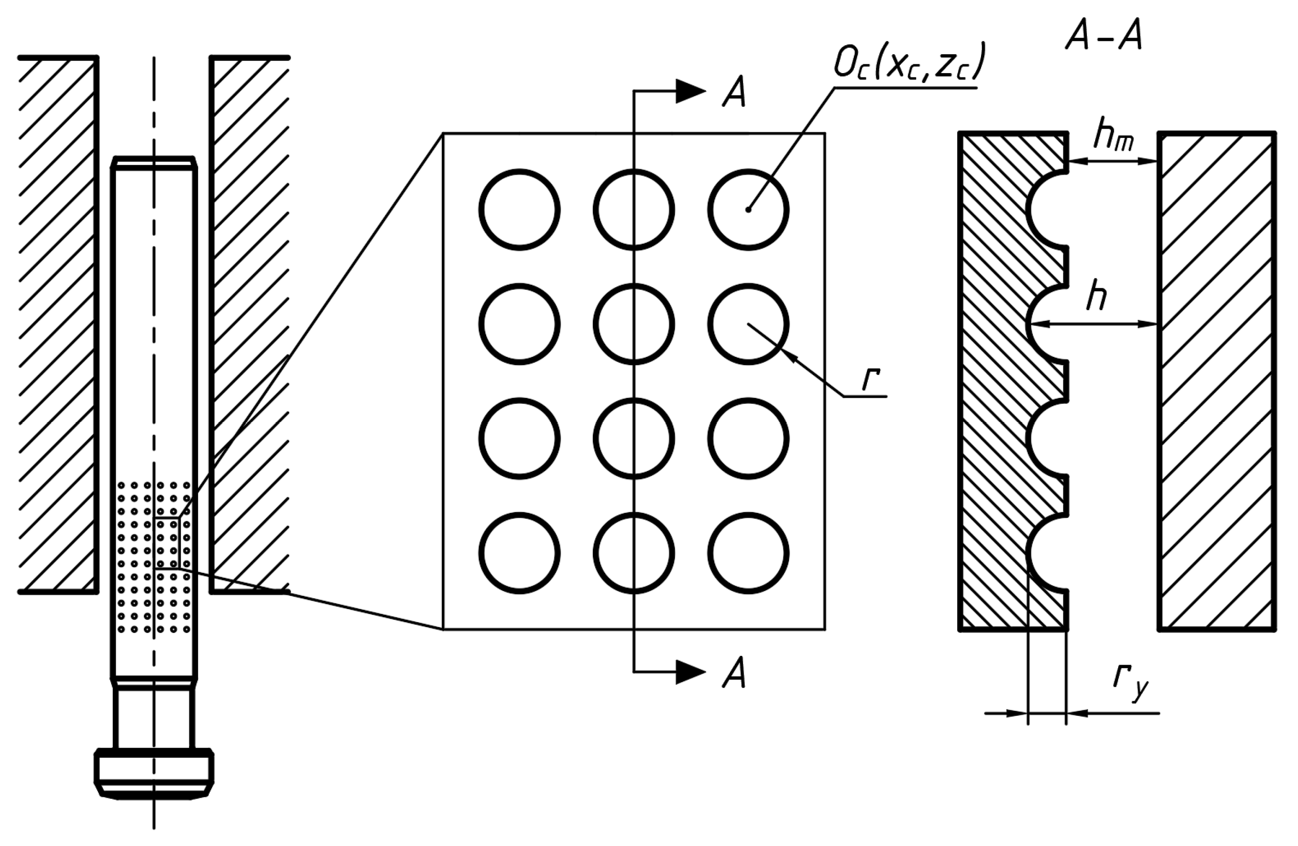
Figure 2 schematically shows the arrangement of micro-dimples on the surface of the plunger. The illustration depicts the unfolded surface of the plunger with a microgeometry relief in the form of ellipsoidal indentations.
The consideration of micro-roughness is performed using the following equation:
h = r y r r 2 ( x x c ) 2 ( z z c ) 2 ,    i f x 2 + z 2 r h m ,    i f x 2 + z 2 > r
where h—thickness of the oil film in any position;
hm—minimum thickness of the film;
r—radius of the dimple;
ry—depth of the dimple;
x, z—coordinates within the dimple cell;
xc, zc—cell center coordinates.
Thus, when the computational grid intersects the micro-dimple region (Figure 2), the minimum thickness of the lubricating layer will be increased by the depth of the micro-dimple at that grid point.
In turn, the minimum thickness of the lubricating layer will be determined as follows:
h m = r 0 ( r p + e cos α ) = h 0 e cos α
where e—eccentricity of the plunger pairs;
r0—inner diameter of the plunger sleeve;
rp—radius of the plunger;
h0 = r0rp—thickness of the oil film in the radial direction when the plunger pair is concentric;
α—angle of application of the force on the crankshaft journal.
The micro-dimple filling density D is determined by the formula:
D = 100 d 2 H 2
where d—micro-dimple diameter;
H = (l + d)—cell height.
Therefore, the distance between micro-dimple l (Figure 3) can be determined as follows:
l = 100 d 2 D d

3. Generalization of the Model

The contact surface of the plunger is oriented in a circumferential direction, as shown in Figure 2. Curvature is neglected here because the magnitude of the diametral clearance (3–4 μm) is sufficiently small compared to the plunger diameter.
To determine the hydrodynamic pressures and lubricating film reaction, a modified Reynolds equation incorporating the boundary conditions of Jakobson–Floberg–Olsson (JFO) was utilized:
φ h ¯ 3 β ¯ 12 μ ¯ ϶ g θ θ x + z ¯ h ¯ 3 β ¯ 12 μ ¯ ϶ g θ θ z ¯ = w 2 x h ¯ θ + τ h ¯ θ ,
where β ¯ = β ψ 2 / μ 0 ω 0 —dimensionless compressibility coefficient of the lubricant;
β dimensional value of the compressibility coefficient of the lubricant;
g ( θ ) switching function between the active region and the cavitation region:
g θ = 1 , i f θ 1 ; 0 , i f θ < 1 ,
where g ( θ ) = 1 —active region;
g ( θ ) = 0 —cavitation region.
The remaining notations in Equation (5) correspond to the notations used in Reference [27].
The degree of lubricating gap fill θ has a dual meaning. In the active region (pressure region where p > 0 ) θ = ρ / ρ c , ρ c is the lubricant density at the cavitation pressure p c . In the cavitation area, where p 0 , p = p c , ρ = ρ c ; in this case, the degree of gap fill θ characterizes the relative amount of lubricating material in the lubricating gap of the tribosystem. Hydrodynamic pressures and the degree of gap fill are related by the following expression:
p ¯ = p ¯ c + g θ β ¯ ln θ .
The system of algebraic equations resulting from Equation (3) in the Elrod algorithm [28] was solved using the point iterative Gauss–Seidel method with respect to the fill factor θij. The switching function g was updated simultaneously at all grid nodes after completing a full iteration cycle. A dimensionless compressibility coefficient of the lubricating fluid β equal to 40 was chosen as the most acceptable value in terms of stability for the iterative procedure.
From the analysis of information sources, it is known that the Elrod algorithm and similar mass conservation algorithms for lubricant in the bearing lubrication film have drawbacks related to numerical instability in solving the system of algebraic equations derived from Equation (5). Additionally, the obtained calculation results depend on the values of β, especially at high eccentricities typical for heavily loaded bearings in thermal engines.
To solve the problem of mathematical modeling of micro-roughness on the plunger surface, a modified Elrod equation has been developed, expressed as follows:
φ h 3 12 μ ¯ e * x ( g Φ ) + 1 a 2 z h 3 12 μ ¯ e * z ( g Φ ) = w 21 2 z h ¯ 1 + ( 1 g ) Φ + τ h ¯ 1 + ( 1 g ) Φ ,
where h ¯ = h / h 0 ; μ ¯ e * = μ e * / μ 0 ; a z ¯ a = z / R ;
a = B / 2 R ; τ = ω 0 t ; w 21 = ( w 2 w 1 ) / ( ω 0 R ) ;
h ¯ , μ ¯ e —dimensionless lubricating film thickness and dimensionless effective viscosity of the lubricant;
B , R —height and radius of the plunger;
μ e * —effective viscosity of the lubricant corresponding to the temperature T e * ;
μ 0 , h 0 , ω 0 —viscosity of the lubricant, the typical thickness of the lubricating film at the central position of the pin, and the rotational speed of the pin, respectively;
w ¯ 21 —dimensionless linear velocity of the pin’s movement;
g—switching function.
The missing notations are provided in Reference [28].

4. The Equation of Motion for a Plunger Pair

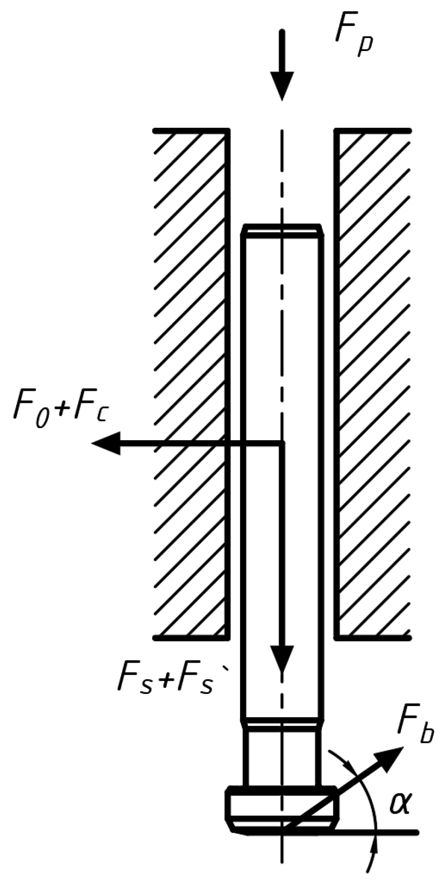
Figure 4 shows the reactions of forces acting on the plunger.
The equation of equilibrium is given as follows:
F 0 + F c = F b cos α ,
where F0—initial lubricating film reaction;
Fc—lubricating film reaction at minimum lubricating film thickness;
Fb—crankshaft force;
α—angle of application of crankshaft force.
F p + F s + F s = F b sin α
where Fp—fuel injection force;
Fs—spring force;
Fs—compression spring force.
The equation of radial balance for the plunger can be expressed as follows:
m 2 c t 2 = F 0 + F c F b cos α
where m—mass of the plunger;
c—instantaneous minimum oil film thickness;
a—angle of force on the distributor shaft.

5. Results of Modeling

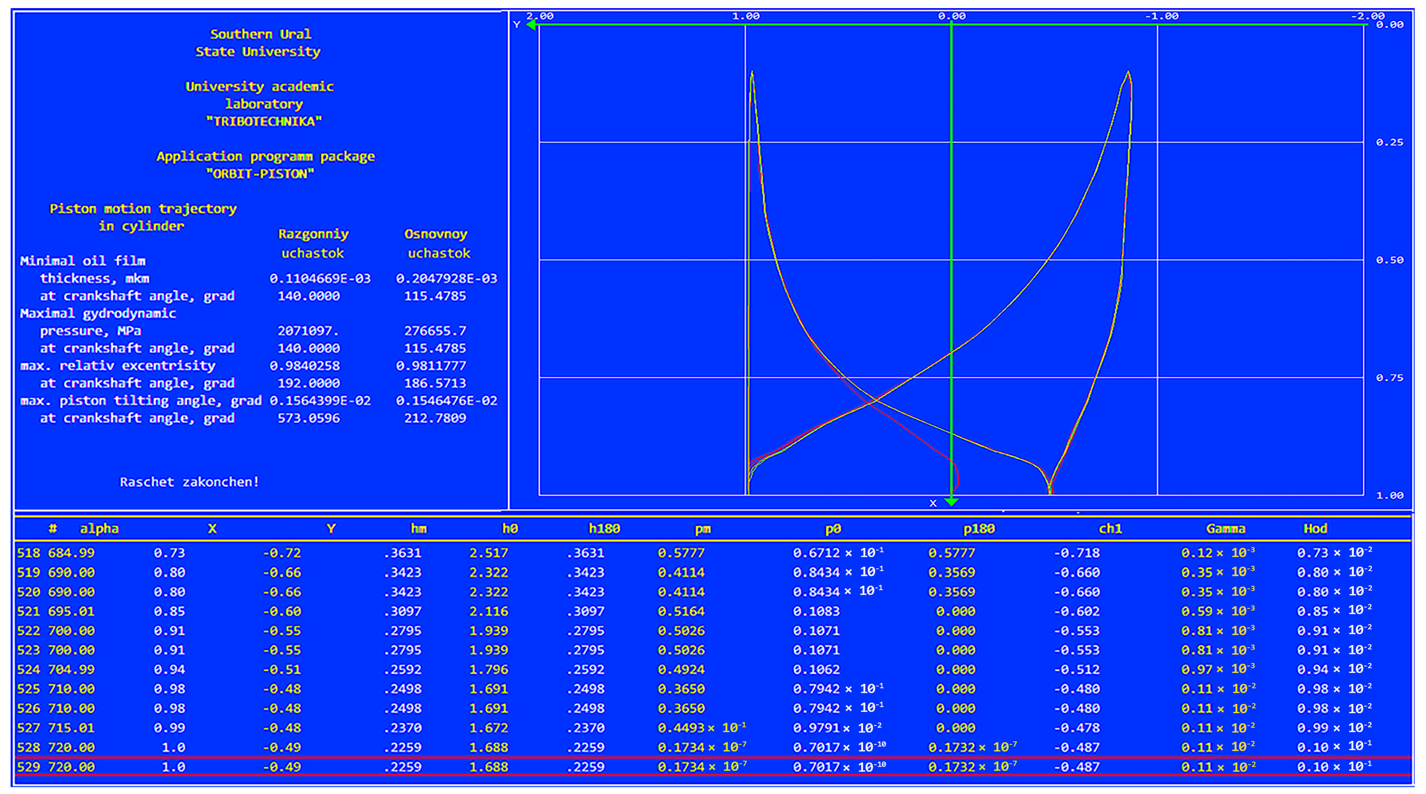
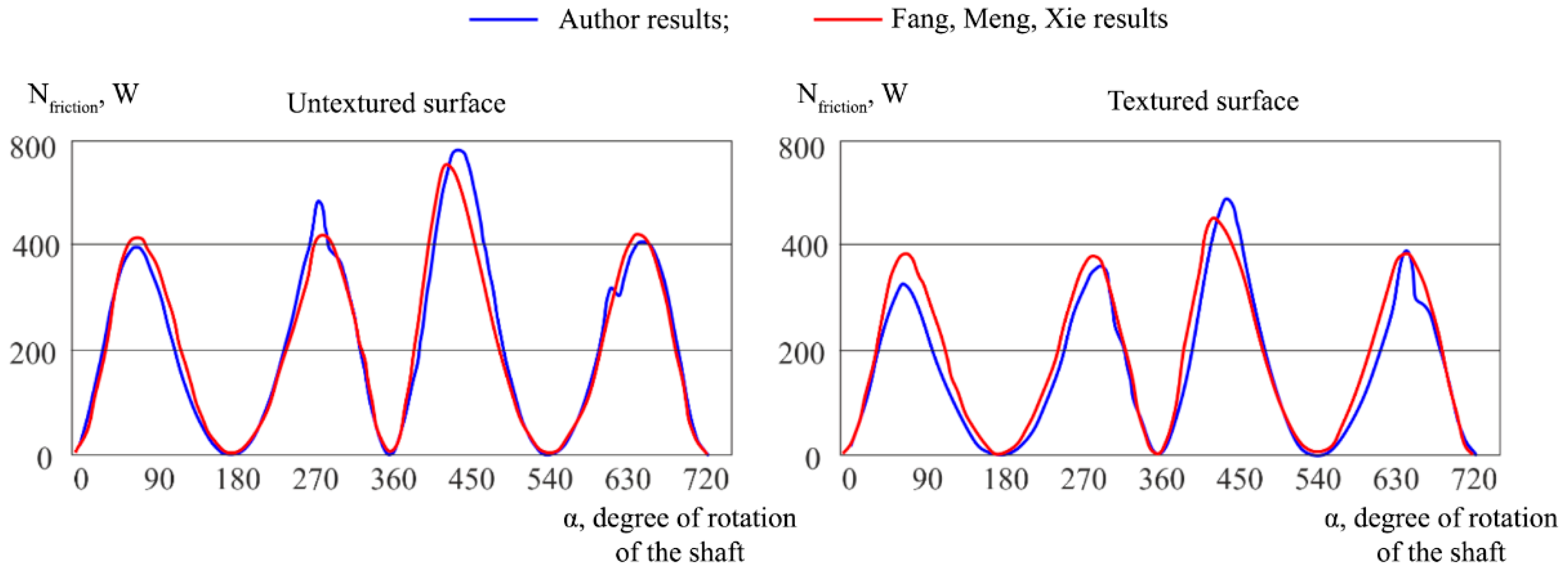
Parametric studies were conducted using the developed software “Microgeometry of Plunger Pairs for Fuel Injection Pumps”, based on the calculation methodology described above. The results of the program are shown in Figure A1 of Appendix A. The software used is a modified version of the software previously used for accounting for micro-dimples in diesel engine pistons, and its validation is presented in Figure 5 [29]. The initial parameters of the plunger pair characteristics and the diesel fuel characteristics are provided in Table 1 and Table 2, respectively.
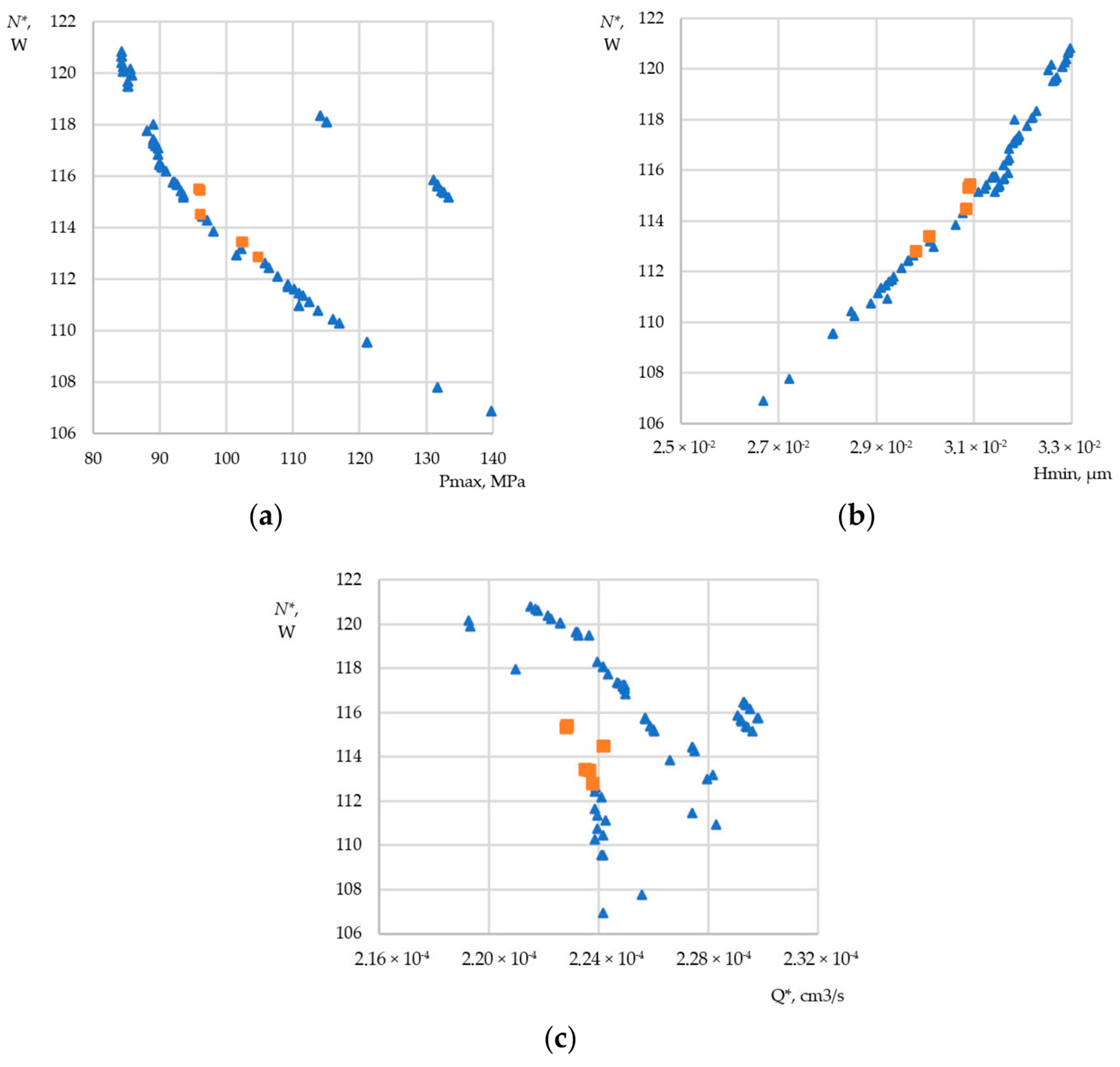
A total of 80 parametric measurements of the hydrodynamic characteristics were performed with different microgeometry parameters (Figure 6), including a variant with its complete absence. Then, six microgeometry variants with average values of the hydrodynamic characteristics were selected (Table 3). These results are presented in Figure 4 as squares.
The variable parameters of the microgeometry were the following: X1 and X2—the start and the end points of the texturing area, respectively; d—the diameter of the micro-cavities; ry—the depth of the micro-cavities; D—the density of surface filling with micro-cavities.
The following quality criteria were selected: h min * , μm—minimum lubricating film thickness per cycle; p max * , MPa—maximum lubricating film pressure per cycle; N*, W—average friction losses; Q*, cm3/s—average fuel leakage.
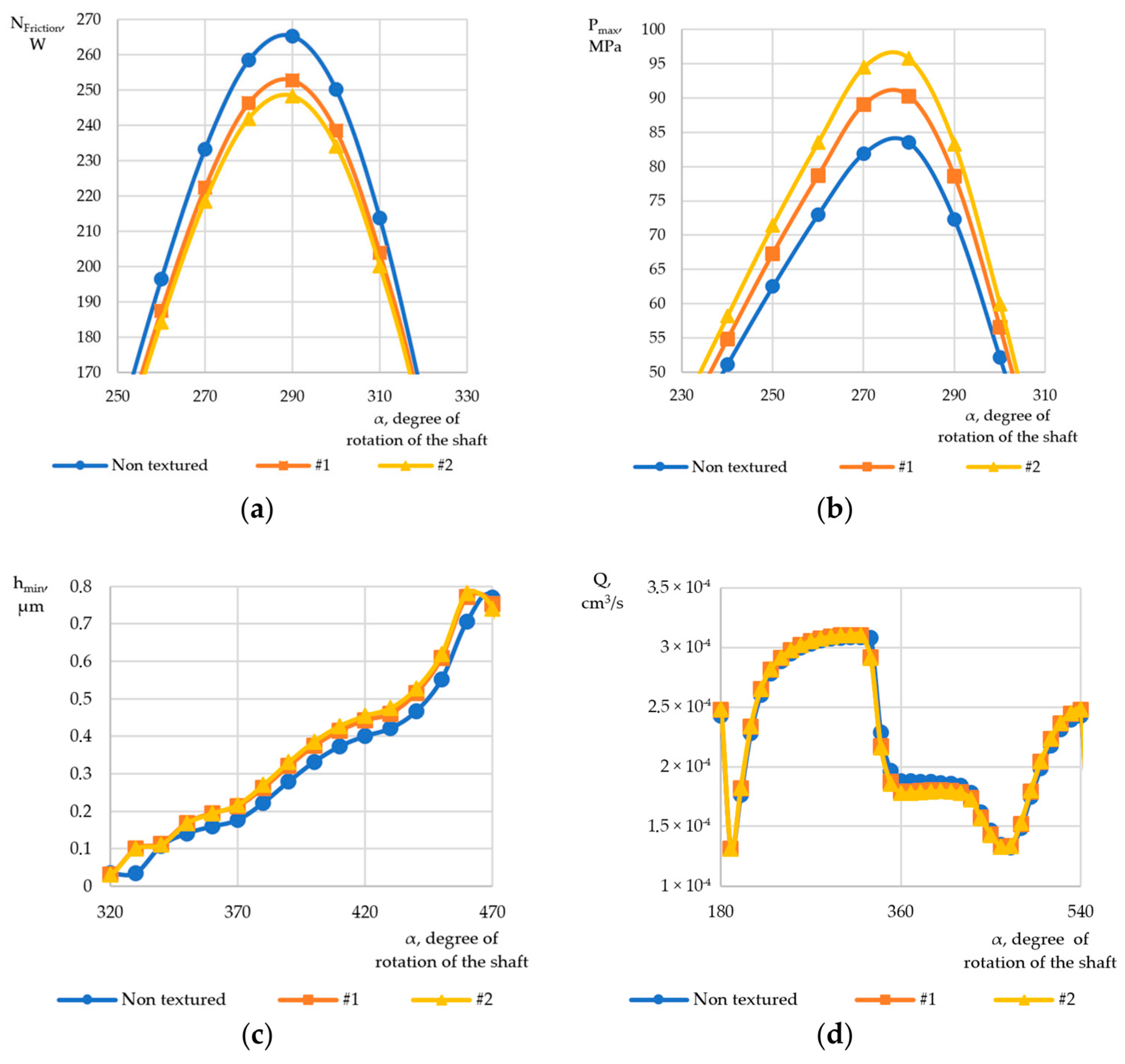
For a graphical representation of changes in hydrodynamic characteristics in the tribosystem depending on the angle of rotation of the distributor shaft of the fuel injection pump (HPFP), the following parameters were chosen: Nfriction—change in average friction losses; Pmax—change in average lubricating film pressure; Hmin—change in average lubricating film thickness; Q—change in maximum fuel leakage.
For better visualization, a graphical comparison of the hydrodynamic characteristics of the plunger pair without using the surface microgeometry and the results considering the surface with micro-dimples are presented in Figure 7. To compare the hydromechanical characteristics, results 1, 2, and 7 (without texturing) of Table 3 were selected.
The graphs shown in Figure 6 indicate a positive effect of applying laser microgeometry to the plunger. Using microgeometry reduced friction losses by 7.5%, while fuel leaks increased by 2.1%. The minimum thickness of the lubricating film decreased by 9%, and the maximum pressure of the lubricating film increased by 20%, which positively affected the load-carrying capacity of the tribosystem.

6. Conclusions

1. A mathematical model considering micro-dimples with variable parameters on the surfaces of plunger pairs has been presented.
2. Based on the provided methodology, software has been developed, and the computational grid has been modified to increase its density and allow for significantly smaller values of microgeometry parameters to be used in the calculations.
3. Based on the results of the performed parametric investigations of the microgeometry of the plunger pair in the “Microgeometry of Plunger Pair for Fuel Injection Pump” program implemented in Visual Fortran, the following conclusions can be drawn: the maximum feasible computational grid size is 12,000 by 7500 cells, enabling the specification of micro-dimple diameters of approximately 5 μm. The depth of the micro-dimples was varied from 2 to 6 μm (with no minimum restrictions).
4. Based on numerous results of the parametric investigations, it can be concluded that texturing has a positive impact on plunger pairs. Out of the total number of calculations exceeding 135 units, two compromise options were identified. In these cases, friction losses were reduced by 7.5%, and the load-carrying capacity of the lubricating film was increased by raising the pressure in the lubricating film by 20%.
5. The results will be further utilized in the design of new high-pressure fuel pumps for common rail systems.

Author Contributions

Conceptualization, K.G.; Methodology, K.G. and Y.R.; Validation, K.G. and Y.R.; Formal Analysis, K.G.; Investigation, K.G. and Y.R.; Resources, K.G. and I.U.; Data Collection, K.G.; Writing—Original Draft Preparation, K.G.; Writing—Review and Editing, I.U.; Visualization, K.G. and I.U.; Supervision, K.G.; Project Administration, K.G., Y.R. and I.U.; Funding Acquisition, K.G., Y.R. and I.U. All of the authors contributed significantly to the completion of this article, conceiving and designing the review, and writing and improving the paper. All authors have read and agreed to the published version of the manuscript.

Funding

This work was supported by a grant from the Russian Science Foundation No. 23-29-10042, accessed on 20 April 2023 (https://rscf.ru/project/23-29-10042/).

Institutional Review Board Statement

Not applicable.

Informed Consent Statement

Not applicable.

Data Availability Statement

There are no data applicable in this study.

Acknowledgments

The authors thank South Ural State University (SUSU) for supporting them.

Conflicts of Interest

The authors declare no conflict of interest.

Appendix A

Figure A1. Program window with parametric calculation results.
Mathematics 11 02637 g0a1

References

  1. Knauder, C.; Allmaier, H.; Sander, D.E.; Salhofer, S.; Reich, F.M.; Sams, T. Analysis of the journal bearing friction losses in a heavy-duty diesel engine. Lubricants 2015, 3, 142–154. [Google Scholar] [CrossRef]
  2. Holmberg, K.; Andersson, P.; Nylund, N.O.; Mäkelä, K.; Erdemir, A. Global energy consumption due to friction in trucks and buses. Tribol. Int. 2014, 78, 94–114. [Google Scholar] [CrossRef]
  3. Brazhenko, V.N.; Mochalin, E.V.; Jian-Cheng, C. Mechanical Admixture Influence in the Working Fluid on Wear and Jamming of Spool Pairs from Aircraft Hydraulic Drives. J. Frict. Wear 2020, 41, 526–530. [Google Scholar] [CrossRef]
  4. Brazhenko, V. The Influence of Contaminated Hydraulic Fluid on the Relative Volume Flow Rate and the Wear of Rubbing Parts of the Aviation Plunger Pump. Aviation 2019, 23, 43–47. [Google Scholar] [CrossRef] [Green Version]
  5. Liu, S.; Zhang, Y.; Ai, C.; Ge, Y.; Li, Z.; Zhu, Y.; Hao, M. A new test method for simulating wear failure of hydraulic pump slipper pair under high-speed and high-pressure conditions. Front. Energy Res. 2023, 10, 1096633. [Google Scholar] [CrossRef]
  6. Zhang, Q.; Fu, Y.; Yuan, Z.; Song, Z. Multi-medium running induced piston pump erosion. Sci. Technol. Rev. 2012, 30, 44–48. [Google Scholar]
  7. Teoh, Y.H.; How, H.G.; Masjuki, H.H.; Nguyen, H.-T.; Kalam, M.A.; Alabdulkarem, A. Investigation on particulate emissions and combustion characteristics of a common-rail diesel engine fuelled with Moringa oleifera biodiesel-diesel blends. Renew. Energy 2019, 136, 521–534. [Google Scholar] [CrossRef]
  8. Huang, J.L.; Xu, H.; Sun, S.Y.; Wang, D. Influence of fuel injection system’s optimization on performance of diesel engine and its injection parameter reoptimization. J. Dalian Marit. Univ. 2017, 43, 2–108. [Google Scholar]
  9. Zhao, J.; Fu, Y.; Ma, J.; Fu, J.; Chao, Q.; Wang, Y. Review of cylinder block/valve plate interface in axial piston pumps: Theoretical models, experimental investigations, and optimal design. Chin. J. Aeronaut. 2021, 34, 1–134. [Google Scholar] [CrossRef]
  10. Segu, D.Z.; Hwang, P. Effectiveness of multishape laser surface texturing in the reduction of friction under lubrication regime. Ind. Lubr. Tribol. 2016, 68, 116–124. [Google Scholar] [CrossRef]
  11. Sun, J.; Zhang, X.; Zhu, J.; Gao, Y.; Wang, H.; Zhao, X.; Teng, Q.; Ren, Y.; Zhu, G. On the lubrication characteristics of piston ring under different engine operation conditions. Ind. Lubr. Tribol. 2019, 72, 101–108. [Google Scholar] [CrossRef]
  12. Cavallo, M.; Frattini, E.; Palmieri, F. Fuel Influence on Single-Piston Common Rail Pump Performance; SAE Technical Paper 2021; N° 2021-24-0063; SAE International: Warrendale, PA, USA, 2021. [Google Scholar] [CrossRef]
  13. Chen, L.; Ren, L.Q.; Zhao, Y.; Zhou, H. The wear-resistance of 3Cr2W8V steel with cave pit non-smooth processed by laser. J. Bionic Eng. 2008, 5, 34–39. [Google Scholar] [CrossRef]
  14. Lee, Y.H.; Schuh, J.K.; Ewoldt, R.H.; Allison, J.T. Simultaneous design of non-Newtonian lubricant and surface texture using surrogate-based multiobjective optimization. Struct. Multidiscip. Optim. 2019, 60, 99–116. [Google Scholar] [CrossRef]
  15. Singh, A.; Patel, D.S.; Ramkumar, J.; Balani, K. Single step laser surface texturing for enhancing contact angle and tribological properties. Int. J. Adv. Manuf. Technol. 2019, 100, 1253–1267. [Google Scholar] [CrossRef]
  16. Fukagai, S.; Le, M.; Lewis, R. Tribological aspects to optimize traction coefficient during running-in period using surface texture. Wear 2019, 424, 223–232. [Google Scholar] [CrossRef]
  17. Etsion, I.; Sher, E. Improving fuel efficiency with laser surface textured piston rings. Tribol. Int. 2009, 42, 542–547. [Google Scholar] [CrossRef]
  18. Kovalchenkova, A.; Ajayi, O.; Erdemir, A.; Fenske, G.; Etsion, I. The effect of laser surface texturing on transitions in lubrication regimes during unidirectional sliding contact. Tribol. Int. 2005, 38, 219–225. [Google Scholar] [CrossRef]
  19. Etsion, I.; Halperin, G. A laser surface textured hydrostatic mechanical seal. Tribol. Trans. 2002, 45, 430–434. [Google Scholar] [CrossRef]
  20. Etsion, I.; Kligerman, Y.; Halperin, G. Analytical and experimental investigation of laser-textured mechanical seal faces. Tribol. Trans. 1999, 42, 511–516. [Google Scholar] [CrossRef]
  21. Yin, B.; Zhou, H.; Xu, B.; Hekun, J. The influence of roughness distribution characteristic on the lubrication performance of textured cylinder liners. Ind. Lubr. Tribol. 2019, 71, 483–493. [Google Scholar] [CrossRef]
  22. Gavrilov, K.; Rozhdestvenskii, Y.; Umurzakov, I. The Construction of Models of Rough Surfaces’ Interaction: Markov’s Approach. Mathematics 2022, 10, 3607. [Google Scholar] [CrossRef]
  23. Jia, H.; Zhou, Z.; Yin, B.; Zhou, H.; Xu, B. Effect of compound texture on lubrication and sealing performance of plunger pump. Lubr. Sci. 2020, 33, 43–59. [Google Scholar] [CrossRef]
  24. Jia, H.; Zhou, Z.; Yin, B.; Zhou, H.; Xu, B. Influence of microdimple on lubrication performance of textured plunger pump. Ind. Lubr. Tribol. 2021, 73, 4–571. [Google Scholar] [CrossRef]
  25. Sinong, X.; Xiuqing, H.; Yinfei, Y.; Liang, L.; Ning, H.; Hanlong, L. Feasible fabrication of a wear-resistant hydrophobic surface. Appl. Surf. Sci. 2019, 463, 923–930. [Google Scholar]
  26. Puzanov, A.; Simakov, A.; Kosorukova, O.; Kotov, V. Perspectives using synthetic corundum in hydraulic drives. J. Phys. Conf. Ser. 2021, 1925, 012021. [Google Scholar] [CrossRef]
  27. Prokopyev, V.N.; Gavrilov, K.V. Optimization of parameters of lightly loaded sliding bearings. Probl. Mech. Eng. Mach. Reliab. 2007, 5, 79–86. (In Russian) [Google Scholar]
  28. Gavrilov, K.V.; Izzatulloev, M.A.; Gritsenko, P.S.; Tsveshko, I.R. Influence of lubrication source location on hydro-mechanical characteristics of lightly loaded bearings in thermal engines. Vestnik of South Ural State University. Ser. Mech. Eng. 2019, 19, 3–21. (In Russian) [Google Scholar]
  29. Fang, C.; Meng, X.; Xie, Y. A piston tribodynamic model with deterministic consideration of skirt surface grooves. Tribol. Int. 2017, 110, 232–251. [Google Scholar] [CrossRef]
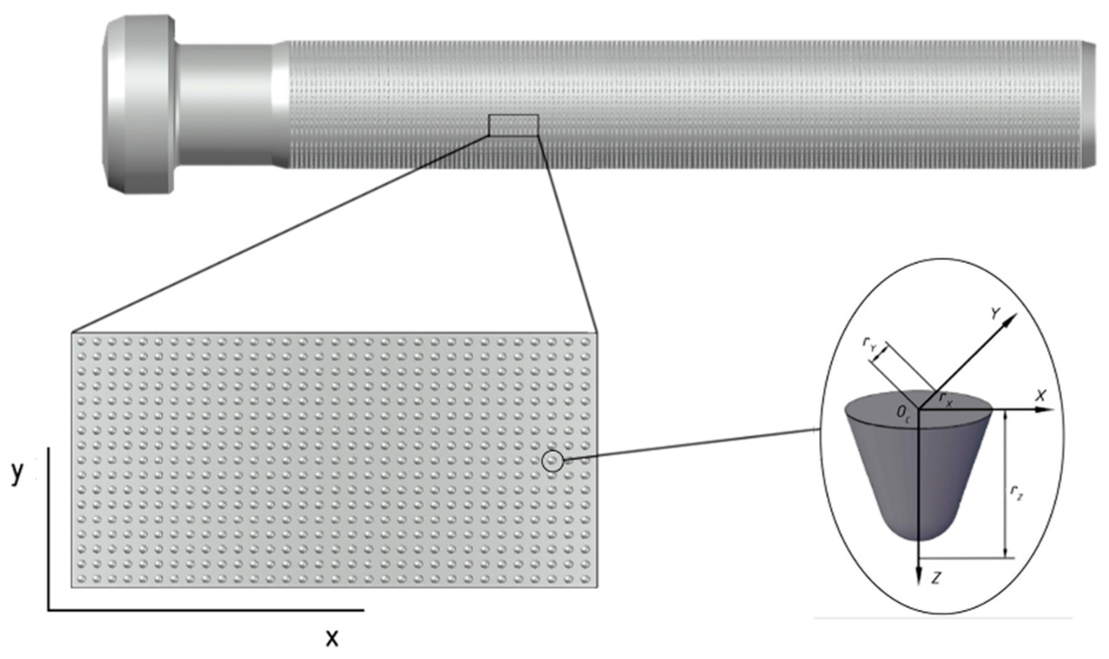
Figure 1. An example of plunger surface texturing.
Mathematics 11 02637 g001
Figure 2. Accounting for micro-roughness in the lubricating layer.
Mathematics 11 02637 g002
Figure 3. Distribution of micro-dimples.
Mathematics 11 02637 g003
Figure 4. Forces acting on the plunger.
Mathematics 11 02637 g004
Figure 5. The dependency of friction losses in the piston on the crankshaft rotation angle of the diesel engine.
Mathematics 11 02637 g005
Figure 6. Reflection of the average friction losses of the parametric results (six selected variants highlighted with squares): (a) in the projection of maximum pressures; (b) in the projection of minimum lubricating film thickness; (c) in the projection of fuel leakage.
Mathematics 11 02637 g006
Figure 7. Variation in hydrodynamic characteristics depending on the angle of rotation of the shaft of the injection pump: (a) change in friction losses; (b) change in maximum pressures of the lubricating film; (c) change in minimum thickness of the lubricating film; (d) change in fuel leaks.
Mathematics 11 02637 g007
Table 1. Initial parameters of the geometry and operating conditions of the plunger pair.
Diameter of Plunger,
mm
Mass of Plunger, gramsLength of Working Part of Plunger, mmEccentricity, mmRotational Speed of Shaft, RPMAverage Velocity of Plunger, m/s
11.056.055.603.533000.77
Table 2. Parameters of diesel fuel.
Density, kg/m3Thermal Capacity, joule/K·kgCoefficient of Thermal Conduction,
W/m·K
Coefficient of Dynamic Viscosity, Pa·s
73020900.1490.0024
Table 3. Parametric results of the hydrodynamic characteristics of the fuel injection pump plunger pair.
Varied ParametersQuality Criteria (Hydrodynamic Characteristics)
X1,
m
X2,
m
d,
m
ry,
m
D,
%
h min * , μm p max * , MPa N*,
W
Q*,
cm3/s
10.1533 × 10−10.4378 × 10−11.19 × 10−54.76 × 10−637.55993.01 × 10−2102.651113.3842.20 × 10−4
20.1583 × 10−10.4444 × 10−11.22 × 10−54.89 × 10−638.88172.98 × 10−2105.045112.7742.21 × 10−4
30.1375 × 10−10.4166 × 10−11.08 × 10−54.33 × 10−633.33263.08 × 10−296.340114.4632.19 × 10−4
40.1535 × 10−10.4380 × 10−11.19 × 10−54.76 × 10−637.60663.01 × 10−2102.724113.3692.20 × 10−4
50.1370 × 10−10.4161 × 10−11.08 × 10−54.32 × 10−633.22033.09 × 10−296.306115.3072.18 × 10−4
60.1361 × 10−10.4148 × 10−11.07 × 10−54.30 × 10−632.96573.09 × 10−295.989115.4062.18 × 10−4
7Plunger pair without microgeometry3.31 × 10−285.603121.9082.17 × 10−4
Disclaimer/Publisher’s Note: The statements, opinions and data contained in all publications are solely those of the individual author(s) and contributor(s) and not of MDPI and/or the editor(s). MDPI and/or the editor(s) disclaim responsibility for any injury to people or property resulting from any ideas, methods, instructions or products referred to in the content.