Article

Robust Tilt-Integral-Derivative Controllers for Fractional-Order Interval Systems

1
School of Electronics and Information Engineering, Taizhou University, Taizhou 318000, China
2
Department of Electrical Engineering, College of Engineering, Jouf University, Sakaka 72388, Saudi Arabia
*
Author to whom correspondence should be addressed.
Mathematics 2023, 11(12), 2763; https://doi.org/10.3390/math11122763
Submission received: 19 April 2023 / Revised: 5 June 2023 / Accepted: 15 June 2023 / Published: 19 June 2023
(This article belongs to the Section Control Theory and Mechanics)

Abstract

:
In this study, an innovative and sophisticated graphical tuning approach is postulated, aimed at the design of tilt-integral-derivative (TID) controllers that are specifically customized for fractional-order interval plants, whose numerators and denominators consist of fractional-order polynomials that are subjected to parametric uncertainties. By leveraging the powerful value set concept and the advanced D-composition technique, a comprehensive set of stabilizing TID controllers is obtained. The validity and effectiveness of the proposed methodology are demonstrated by some examples, which vividly illustrate its remarkable performance and potential.

1. Introduction

Fractional calculus is a branch of mathematics that extends the concept of differentiation and integration to non-integer orders. While traditional calculus operations are limited to integer orders, fractional calculus enables the computation of derivatives and integrals of any real or complex order, including fractional orders. Fractional calculus has become increasingly relevant in recent years, with applications in numerous fields, such as physics, engineering, finance, and biology: for instance, in physics, fractional calculus has been used to describe anomalous diffusion in systems with memory, while in finance, it has been applied to the modeling of financial time series with long-range dependence [1,2,3,4].
Fractional-order controllers are a type of controller that utilizes fractional calculus principles, so as to achieve control performance superior to traditional integer-order controllers. Fractional-order controllers offer several advantages, such as providing better damping and faster response, enhanced stability, and robustness against parameter variations [5,6]. Fractional-order controllers can achieve these improvements with fewer components and less complexity than traditional controllers. Fractional-order controllers are widely used in various engineering fields, including control systems [7,8,9], robotics [10], power electronics [11], and process control [12]. Fractional-order controllers have also shown promising results in biomedical applications, such as controlling glucose levels in diabetic patients [13], and in active suspension systems for improving vehicle ride quality [14].
The modeling of complex real-world systems is often plagued by inherent uncertainties and inaccuracies that can lead to unstable control performance: to account for this, engineers frequently employ interval uncertainty structures to incorporate the uncertain parameters of the system model into a real interval [15,16]. This approach allows for a more realistic representation of the system’s behavior. The problem of stabilizing and improving the performance of interval systems, including those of both integer and fractional orders, has become a crucial challenge in the field of control [17,18]. Indeed, interval uncertainty modeling has emerged as one of the most popular techniques, among engineers, for dealing with uncertain systems, offering a versatile and effective means of mitigating the detrimental effects of uncertainty and improving control performance in the face of real-world complexity [15].
The literature review makes clear that the examination of the stability of an interval fractional system encompasses two principal categories of methods: the linear matrix inequalities (LMIs) method [19,20] and the graphical method [21]. The LMI method may have limitations when applied to fractional-order systems with non-commensurate orders. Additionally, the process of solving LMIs can occasionally introduce conservatism, which can affect the accuracy of stability testing [22]. The graphical method for analyzing the stability of interval fractional systems is primarily rooted in the zero exclusion principle [23]. The graphical method entails plotting the value set of the characteristic function of the interval fractional system at each frequency, and determining if zero is excluded by the value set [24]. By presenting both necessary and sufficient conditions for the stabilization of specific types of interval fractional systems, such as fractional systems with incommensurate orders and fractional delay systems, the graphical method offers a powerful tool for engineers to design and analyze control systems under conditions of significant uncertainty and variability. Moreover, the graphical method offers the advantage of providing a clear and intuitive representation of the system’s behavior in the frequency domain, enabling engineers to identify potential stability issues and make informed decisions about controller design and implementation [25,26]. Paper [27] introduced a robust stability checking function that employs the zero exclusion principle to assess the stability of fractional-order interval systems. Furthermore, in a study conducted by [28], a novel method was proposed, by which to investigate the robust stability of fractional-order interval systems with an interval time delay, utilizing the concept of the value set.
The quest to determine the stabilizing region of fractional-order controllers has garnered significant attention in recent years. To this end, several graphical tuning methods have been developed, to calculate the stabilizing region of fractional-order proportional-integral-derivative (FOPID) and fractional-order proportional-integral (FOPI) controllers, as outlined in [29,30]. In addition, an algorithm for stabilizing fractional-order systems using FOPID controllers was introduced in [31,32]. The computation of the stabilizing region of FOPID controllers provides several advantages: for example, it enables the identification of a set of stabilizing FOPID controllers, rather than just a single controller, thus allowing for a more flexible choice of controller parameters. This approach offers an effective means of improving the performance and stability of complex control systems, and has the potential to yield significant advancements in the field of control theory and engineering [33].
In recent years, the tuning methodology applied to TID controllers has garnered significant scholarly attention [34,35]. In [36], a novel approach was introduced, to devise TID controllers for fractional-order systems. This technique, however, falls short in ensuring the robust stability of interval systems, which has spurred the author of the current paper to develop a novel methodology for achieving robust stabilization of fractional-order interval systems with TID controllers. In summary, the paper presents the following novel contributions:
  • Analysis of the robust stability of the closed-loop system for interval fractional-order plants using TID controllers;
  • Calculation of the robust stability region of TID controllers for interval fractional-order systems;
  • Introduction of a robust stability testing function, to investigate the robust stability of the interval system;
  • Presentation of an auxiliary function aimed at enhancing the control requirements for disturbance rejection.
The present paper is structured as follows: Section 2 elaborates on TID controllers and the corresponding closed-loop control system; Section 3 introduces several robust stabilization methods utilizing TID controllers in the presence of uncertainties; Section 4 presents the simulation results conducted to validate the proposed methods; Section 5 concludes the paper with a summary of the key findings.

2. Background and Preliminaries

Upon careful examination of Figure 1, it is pertinent to direct our attention towards the single-input-single-output (SISO) fractional-order system under consideration. The TID controller is embodied in the block C ( s ) , which assumes a pivotal role in regulating and governing the system’s behavior. To be more precise, the TID controller exhibits a highly intricate and finely-tuned structure, as it operates through a combination of tilt, integral, and derivative actions, which are designed to achieve system performance and stability. The transfer function of TID controllers can be precisely defined as follows:
C ( s ) = K t s 1 n + K i s + K d s ,
where 1 n ( 0 , 1 ) , and K t , K i , and K d are real numbers. The fractional-order interval plant G ( s ) can be defined as follows:
G ( s ) = N G ( s ) D G ( s ) = i b = 0 n b b i b s β i b i a = 0 n a a i a s α i a ,
where β 0 = 0 < β 1 < < β n b and α 0 = 0 < α 1 < < α n a . It is imperative to note that the fractional-order plant G ( s ) is characterized by a set of coefficients, whose values are subject to interval uncertainties, i.e., b i b [ b i b , b i b + ] , b n b 0 and a i a [ a i a , a i a + ] , a n a 0 . The presence of such uncertainties, arising from various sources—such as measurement errors, modeling approximations, and external disturbances—renders the system’s behavior highly intricate and nonlinear, thereby posing a formidable challenge to the synthesis of robust and high-performance control strategies. Based on the preceding explanations and the information presented in Figure 1, it is possible to derive the characteristic function of the closed-loop control system, as follows:
Δ ( s ) = s D G ( s ) + ( K t s 1 1 n + K i + K d s 2 ) N G ( s ) .
Definition 1.
According to reference [37], it can be deduced that the value set of N G ( s ) is a convex polygon whose vertices can be determined by the following pattern:
V 1 N ( s ) = b 0 + b 1 s β 1 + + b n b s β n b , V 2 N ( s ) = b 0 + + b 1 s β 1 + + b n b s β n b , V 3 N ( s ) = b 0 + b 1 + s β 1 + + b n b s β n b , V 2 n b + 1 N ( s ) = b 0 + + b 1 + s β 1 + + b n b + s β n b .
The determination of the exposed edges can be accomplished by utilizing (4). Specifically, it can be observed that V 1 N ( s ) and V 2 N ( s ) possess identical structures, with the exception of b 0 . As a result, it is plausible to designate one of the edges as e ( V 1 N ( s ) , V 2 N ( s ) ) , where ( e ( x 1 , x 2 ) = η x 1 + ( 1 η ) x 2 ) , η [ 0 , 1 ] . The remaining edges can be constructed through a comparable method. To form a comprehensive collection of vertices, all V i N ( s ) (where i ranges from 1 to 2 n b + 1 ) can be included in a single set, as follows:
P E N ( s ) = { e ( V 1 N ( s ) , V 2 N ( s ) ) , e ( V 1 N ( s ) , V 3 N ( s ) ) , , e ( V 2 n b + 1 1 N ( s ) , V 2 n b + 1 N ( s ) ) } .
Similarly, V r D ( s ) (where r is an integer that ranges from 1 to 2 n a + 1 ) and P E D ( s ) can be defined as the vertices and exposed edges, respectively, of D G ( s ) .
Remark 1.
The aim of this remark is to ascertain the domain of stabilization in the ( K t , K i ) plane, while keeping the K d values constant, such that the following polynomial (6) adheres to the Hurwitz criterion:
Δ 0 ( s ) = s D G 0 ( s ) + ( K t s 1 1 n + K i + K d s 2 ) N G 0 ( s ) ,
where N G 0 ( s ) and D G 0 ( s ) denote one of the selected elements of N G ( s ) and D G ( s ) , respectively. By performing a partition of Δ 0 ( j ω ) into its constituent real and imaginary components, and subsequently setting them equal to zero, we are able to derive the following result:
A 11 K t + A 12 K i = B 1 A 21 K t + A 22 K i = B 2 .
Ultimately, upon solving Equation (7), the parameters K t and K i can be ascertained by the following means:
K t = B 1 A 22 A 12 B 2 A 11 A 22 A 12 A 21 K i = B 2 A 11 A 21 B 1 A 11 A 22 A 12 A 21 ,
where
A 11 = real ( s 1 1 n N G 0 ( s ) ) A 12 = real ( N G 0 ( s ) ) B 1 = real ( s D G 0 ( s ) + K d s 2 N G 0 ( s ) ) A 21 = imag ( s 1 1 n N G 0 ( s ) ) A 22 = imag ( N G 0 ( s ) ) B 2 = imag ( s D G 0 ( s ) + K d s 2 N G 0 ( s ) ) .
The functions denoted by real (.) and imag (.) correspond, respectively, to the real and imaginary components of a complex number. By verifying a singular test point within each distinct region, it is feasible to determine the stabilizing region [31,32,36].
In this paper, we utilize the zero exclusion principle, as defined below, to assess the robust stability of the fractional-order closed-loop control system.
Zero Exclusion Principle [25]: The system is robustly stable if and only if Δ ( s ) has at least one stable polynomial and 0 Δ ( j ω ) for ω [ 0 , ) .

3. Main Results

The present section can be subdivided into two distinct subsections. Firstly, within the confines of the ‘Algorithm to Determine Robust Stability Region of TID Controllers’ subsection, a theorem is presented that facilitates the analysis of the robust stability of the characteristic function (3). Secondly, an algorithm is proposed that enables the computation of the stabilizing region of TID controllers for the fractional-order interval plant G ( s ) . Furthermore, the ‘Robust Stability Checking Function’ subsection features an auxiliary function that is a tool for investigating the robust stability of the closed-loop control system.

3.1. Algorithm to Determine Robust Stability Region of TID Controllers

The primary aim of this subsection is to delineate the robust stability region of TID controllers, with respect to fractional-order interval systems, as portrayed in Figure 1. Consequently, the subsequent theorem serves to ascertain a comprehensive set both of the necessary and of the sufficient conditions that are indispensable for verifying the robust stability of the aforementioned system.
Theorem 1.
The characteristic function (4) can be robustly stable if and only if the characteristic functions Δ i 1 N ( s ) ( i 1 = 1 , , 2 n b + 1 ) , stipulated in (10), and Δ i 2 D ( s ) ( i 2 = 1 , , 2 n a + 1 ) , enumerated in (11), are also robustly stable:
Δ i 1 N ( s ) = s D G ( s ) + ( K t s 1 1 n + K i + K d s 2 ) V i 1 N ( s ) , i 1 = 1 , 2 n b + 1 ;
Δ i 2 D ( s ) = s V i 2 D ( s ) + ( K t s 1 1 n + K i + K d s 2 ) N G ( s ) , i 2 = 1 , , 2 n a + 1 .
Proof. 
Drawing on the zero exclusion principle, it is clear that the sole necessity is to scrutinize the proviso of 0 Δ ( j ω ) .
The ‘if’ portion: In the event that the functions Δ i 1 N ( s ) , with i 1 ranging from 1 to 2 n b + 1 , as well as Δ i 2 D ( s ) , with i 2 ranging from 1 to 2 n a + 1 , are endowed with the trait of robust stability, it logically follows that for s = j ω one can straightforwardly derive the conclusion that:
( K t s 1 1 n + K i + K d s 2 ) V i 1 N ( s ) s D G ( s ) s V i 2 D ( s ) ( K t s 1 1 n + K i + K d s 2 ) N G ( s ) .
A perspicacious observation can be made from Equation (12) that the value sets s ( K t s 1 1 n + K i + K d s 2 ) V i 1 N ( s ) and s D G ( s ) (consequently s V i 2 D ( s ) and ( K t s 1 1 n + K i + K d s 2 ) N G ( s ) ) have no overlap in the complex plane, thus rendering it manifest that 0 is not an element of Δ ( j ω ) .
The ‘only if’ portion: The robust stability of the characteristic function (4) serves as the foundation upon which the zero exclusion principle is invoked, culminating in the unequivocal fact that 0 is devoid of membership in Δ ( j ω ) . The application of said principle unequivocally establishes the position of the origin outside the set of values constituting Δ ( j ω ) . Thus, by invoking Equation (10), one is able to infer the robust stability of Δ i 1 N ( s ) , indexed by i 1 spanning the set of integers from 1 to 2 n b + 1 , as well as Δ i 2 D ( s ) , indexed by i 2 spanning the set of integers from 1 to 2 n a + 1 , as outlined in (10) and (11), respectively. □
The task at hand now centers exclusively around ascertaining the robust stability domain that characterizes the characteristic functions Δ i 1 N ( s ) and Δ i 2 D ( s ) , as enunciated in (10) and (11), respectively. In order to accomplish this end, the computational procedure presented in Stabilization Algorithm outlines the method for ascertaining the stabilizing region.
Stabilization Algorithm:
Step 1. Attain the vertices denoted as V i 1 N ( s ) and V i 2 D ( s ) , by availing oneself of the process outlined in Definition 1;
Step 2. Utilize the D-decomposition technique, as delineated in Remark 1, to apply it proficiently to both s P E D ( s ) + ( K t s 1 1 n + K i + K d s 2 ) N G ( s ) and s V i 2 D ( s ) + ( K t s 1 1 n + K i + K d s 2 ) P E N ( s ) ;
Step 3. The ultimate stabilizing domain of the TID controllers for fractional-order interval plants can be defined as the intersection of all the stable regions calculated in Step 2.

3.2. Robust Stability Checking Function

The application of a robust stability checking function constitutes a prevalent methodology for evaluating the robust stability of an interval system that has been controlled by a pre-designed TID controller: hence, the following theorem introduces an auxiliary function, of ascertaining the robust stability of the closed-loop system, given a pre-designed controller.
Theorem 2.
Assume that the TID controller can stabilize one member of the interval system, and let H 1 N , H 2 N , , H l n N and H 1 D , H 2 D , , H l d D be all edges of P E N ( s ) and P E D ( s ) , respectively. Then, the system is robustly stable if and only if it can be ascertained that the inequality H ( ω ) > 0 , defined in Equation (13), holds true:
H ( ω ) min { H 1 ( ω ) , , H l n ( ω ) , H 1 + ( ω ) , , H l d + ( ω ) } , H i ( ω ) = min r = 1 , , 2 n a + 1 T R s V r D ( s ) ( N c H i N ) , H i + ( ω ) = min r = 1 , , 2 n b + 1 T R N c V r N ( s ) ( s H i D ) ,
where N c = ( K t s 1 1 n + K i + K d s 2 ) and, for the polynomials V x ( s ) , V y ( s ) , and V z ( s ) , we define T R V z ( s ) ( e ( V x ( s ) , V y ( s ) ) as
T R V z ( s ) ( e ( V x ( s ) , V y ( s ) ) = | V x ( s ) + V z ( s ) | + | V x ( s ) + V y ( s ) | | V z ( s ) V y ( s ) | .
Proof. 
Drawing on the findings from Remark 1, it becomes evident that the value sets of Δ i 1 N ( s ) and Δ i 2 D ( s ) constitute two convex polygons, each situated within the complex plane. Assuming that the triangle inequality holds true for every two consecutive vertices of Δ i 1 N ( s ) , one can deduce that 0 is not a member of Δ i 1 N ( s ) , which ultimately implies that the inequalities H i ( ω ) > 0 , i = 1 , , l n are satisfied. Similarly, adherence to the inequalities H i + ( ω ) > 0 , i = 1 , , l d results in the exclusion of 0 from Δ i 2 D ( s ) i.e., 0 Δ i 2 D ( s ) . Consequently, if the inequality H ( ω ) > 0 is met, then, leveraging Theorem 1 and the zero exclusion principle, the proof is established. □

3.3. Effective Output Disturbance Attenuation

The sensitivity function is responsible for characterizing critical feedback system properties, such as robust performance and disturbance rejection. The smallness of the sensitivity function in the low frequency range helps to achieve the desired performance of the closed-loop system. Consequently, in order to meet these requirements, a robust fractional-order controller denoted as C ( s ) must adhere to the subsequent inequality:
| S ( s ) | = 1 1 + C ( s ) G ( s ) < M s ( s ) ,
where M s ( j ω ) denotes the weighting function that characterizes the performance specifications’ frequency response and disturbance magnitude [38]. To further enhance the performance specifications, the designer must satisfy the inequality H S ( ω ) < 0 , in accordance with the maximum modulus principle [39] and Theorems 1 and 2. The function H S ( ω ) can be obtained as follows:
H S ( ω ) max { H i S | i = 1 , 2 } ,
where
H 1 S ( ω ) max i = 1 , , 2 n b + 1 . H i d ( ω ) , H i d ( ω ) max e h D D Q E D e h D D F s ( j ω ) , h D = 1 , 2 , , l D , Q E D { h 1 D , h 2 D , , h l D D } , h 1 D 1 1 + ( K t s 1 1 n + K i + K d s 2 ) V i N ( j ω ) s H 1 D , h 2 D 1 1 + ( K t s 1 1 n + K i + K d s 2 ) V i N ( j ω ) s H 2 D , h l D D 1 1 + ( K t s 1 1 n + K i + K d s 2 ) V i N ( j ω ) s H l D D .
H 2 S ( ω ) max i = 1 , , 2 n a + 1 . H i n ( ω ) , H i n ( ω ) max e h N N Q E N e h N N F s ( j ω ) , h N = 1 , 2 , , l N , Q E N { h 1 N , h 2 N , , h l N N } , h 1 N 1 1 + ( K t s 1 1 n + K i + K d s 2 ) H 1 N s V i D ( j ω ) , h 2 N 1 1 + ( K t s 1 1 n + K i + K d s 2 ) H 2 N s V i D ( j ω ) , h l N N 1 1 + ( K t s 1 1 n + K i + K d s 2 ) H l N N s V i D ( j ω ) .

4. Illustrative Examples

Example 1.
Consider the following plant, as discussed in [36]:
G ( s ) = 9 s 3 + 3 s 2 + 11 s + 9 .
Let us now regard G ( s ) in (19) as an interval plant, expressed as follows:
G ( s ) = [ 8.5 , 9.5 ] s 3 + [ 2.5 , 3.5 ] s 2 + [ 10.5 , 11.5 ] s + [ 8.5 , 9.5 ] .
Utilizing the values of K d = 0 and 1 n = 0.9 for the TID controller, the first stage of the Stabilization Algorithm yields a set of vertices for N G ( s ) = [ 8.5 , 9.5 ] and D G ( s ) = [ 8.5 , 9.5 ] + [ 10.5 , 11.5 ] s + [ 2.5 , 3.5 ] s 2 + s 3 , which can be derived in the following manner:
V 1 N ( s ) = 8.5 V 2 N ( s ) = 9.5
V 1 D ( s ) = 8.5 + 10.5 s + 2.5 s 2 + s 3 V 2 D ( s ) = 9.5 + 10.5 s + 2.5 s 2 + s 3 V 3 D ( s ) = 8.5 + 11.5 s + 2.5 s 2 + s 3 V 4 D ( s ) = 9.5 + 11.5 s + 2.5 s 2 + s 3 V 5 D ( s ) = 8.5 + 10.5 s + 3.5 s 2 + s 3 V 6 D ( s ) = 9.5 + 10.5 s + 3.5 s 2 + s 3 V 7 D ( s ) = 8.5 + 11.5 s + 3.5 s 2 + s 3 V 8 D ( s ) = 9.5 + 11.5 s + 3.5 s 2 + s 3 .
The exposed edges P E N ( s ) and P E D ( s ) can be defined as
P E N ( s ) = { e ( V 1 N ( s ) , V 2 N ( s ) ) }
P E D ( s ) = { e ( V 1 D ( s ) , V 2 D ( s ) ) , e ( V 1 D ( s ) , V 3 D ( s ) ) , e ( V 1 D ( s ) , V 5 D ( s ) ) , e ( V 2 D ( s ) , V 4 D ( s ) ) , e ( V 2 D ( s ) , V 6 D ( s ) ) , e ( V 3 D ( s ) , V 4 D ( s ) ) , e ( V 3 D ( s ) , V 7 D ( s ) ) , e ( V 4 D ( s ) , V 8 D ( s ) ) , e ( V 5 D ( s ) , V 6 D ( s ) ) , e ( V 5 D ( s ) , V 7 D ( s ) ) , e ( V 6 D ( s ) , V 8 D ( s ) ) , e ( V 7 D ( s ) , V 8 D ( s ) ) } .
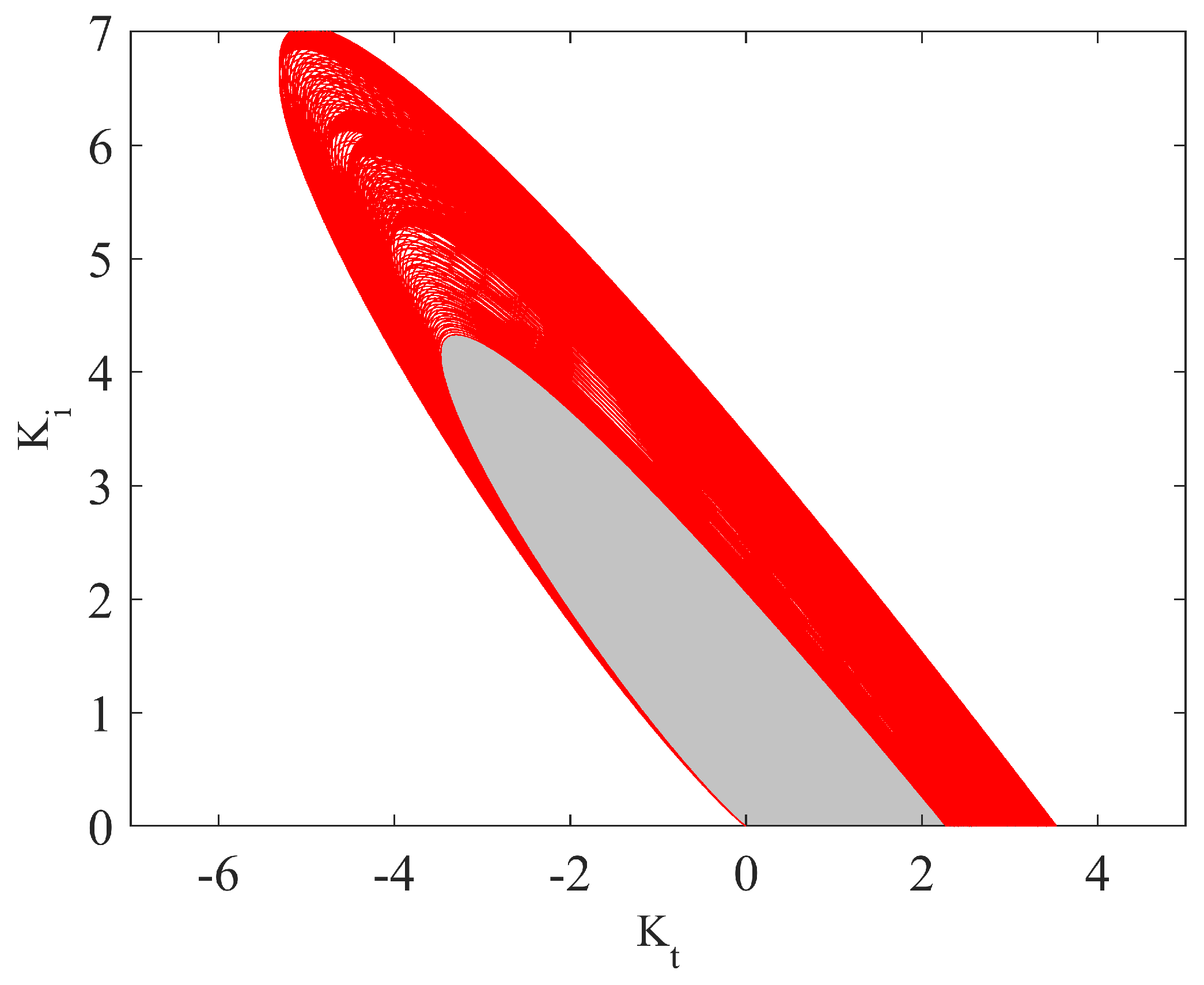
Upon the successful execution of steps 2 and 3, delineated in the eminentStabilization Algorithm, the robust stability region of the TID controllers can be ascertained, and is shown in Figure 2 (gray region). In Figure 2, the red color denotes the boundaries of the stability region for all polynomials of Δ i 1 N ( s ) and Δ i 2 D ( s ) . To test the stability of any member of the uncertainty space of the characteristic function, the graphical method proposed in [40] is used. As an illustrative example, consider the subsequent characteristic function:
Δ 0 ( s ) = s ( 8.5 + 10.5 s + 2.5 s 2 + s 3 ) + 8.5 ( s 0.1 + 1 ) .
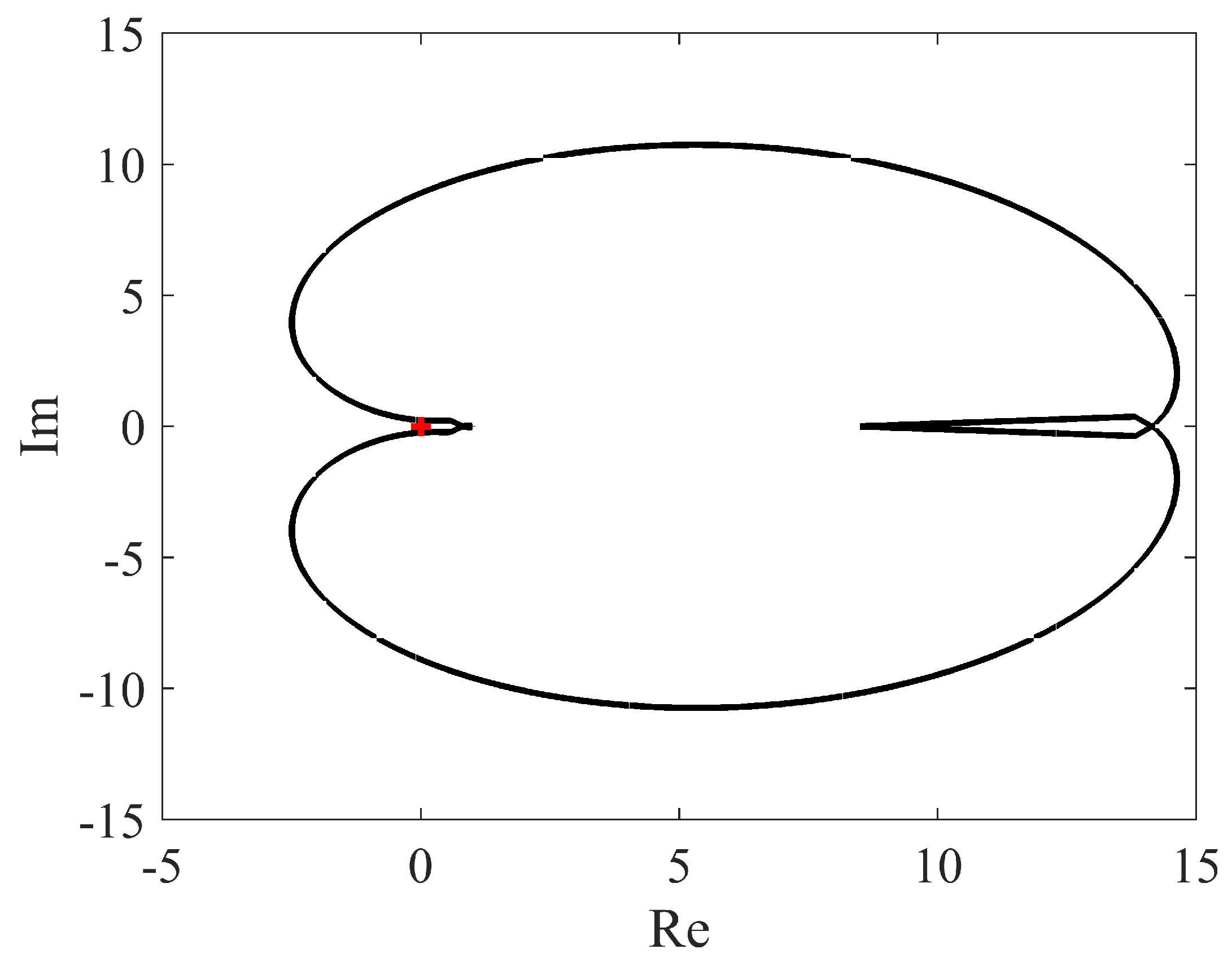
Consequently, it is imperative that we generate a graphical representation of the Mikhailov’s plot, which is expressed as ψ ( s ) = Δ 0 ( s ) ( s + 1 ) 4 , where s equals the complex frequency j ω , and is graphically portrayed in Figure 3. The depicted figure shows that the function Δ 0 ( s ) , due to the fact that the curve does not encompass the origin, is stable. The approach proposed in reference [36] is inadequate for computing the robust stability region of TID controllers within the framework of interval systems; however, as demonstrated by the findings presented in the current paper, this issue has been effectively addressed and improved upon.
Example 2.
Given the interval plant G ( s ) , as denoted in (20), Theorem 2 is employed to scrutinize and determine which controller, either C 1 ( s ) in (26) or C 2 ( s ) in (28), has the capability to effectively stabilize the system in a robust manner:
C 1 ( s ) = 0.25 s 0.9 + 0.15 s ;
C 2 ( s ) = 2 s 0.9 + 1 s .
In accordance with Theorem 2, our preliminary task entails evaluating the stability of a singular selected component of the interval system. To accomplish this, we designate either Δ 1 0 ( s ) or Δ 2 0 ( s ) as the elected member, based on the corresponding controller being considered—namely, C 1 ( s ) , as represented in (26), or C 2 ( s ) , as represented in (28):
Δ 1 0 ( s ) = s ( 9.5 + 11.5 s + 2.5 s 2 + s 3 ) + 8.5 ( 0.25 s 0.1 + 0.15 ) ;
Δ 2 0 ( s ) = s ( 9.5 + 11.5 s + 2.5 s 2 + s 3 ) + 8.5 ( 2 s 0.1 + 1 ) .
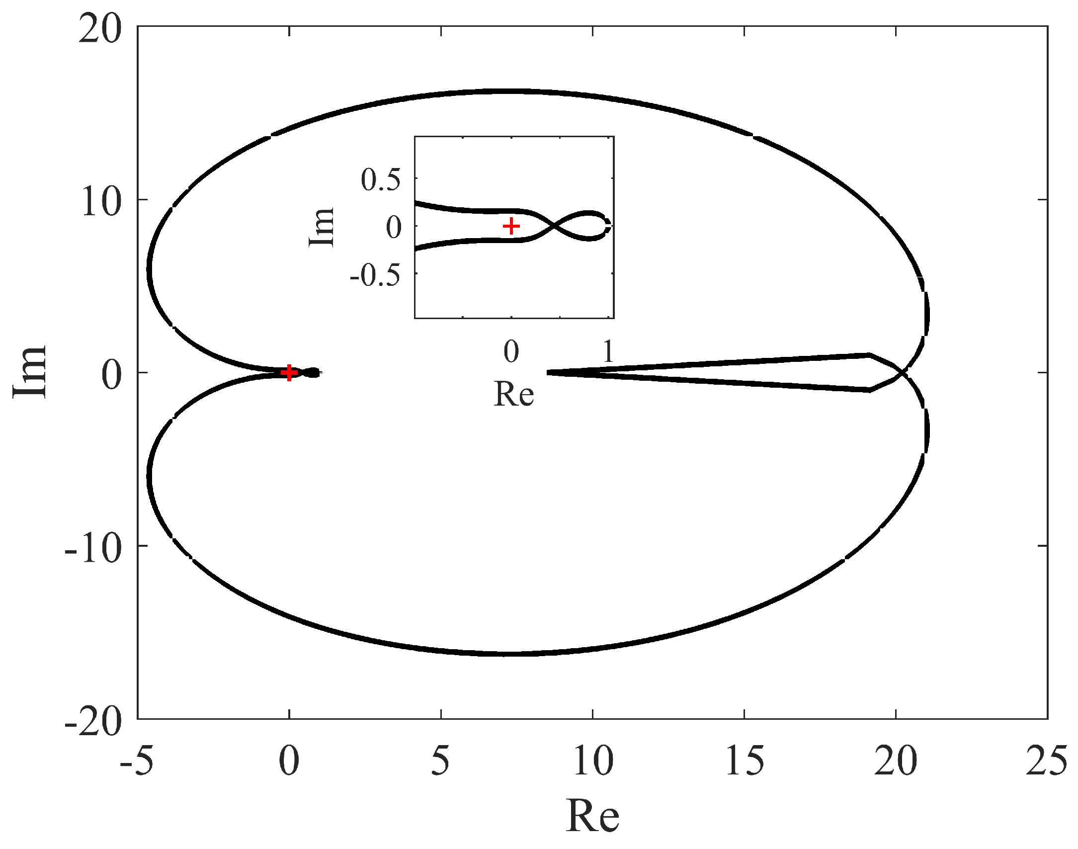
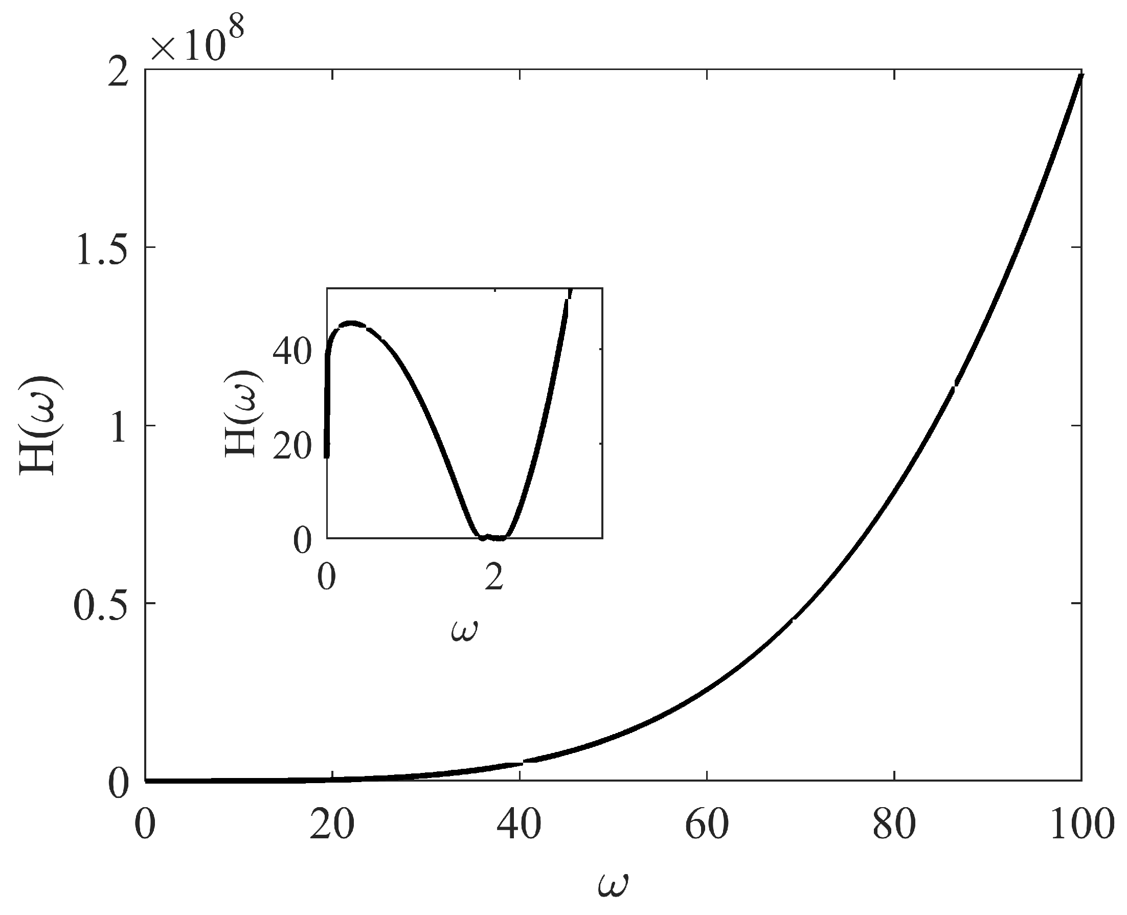
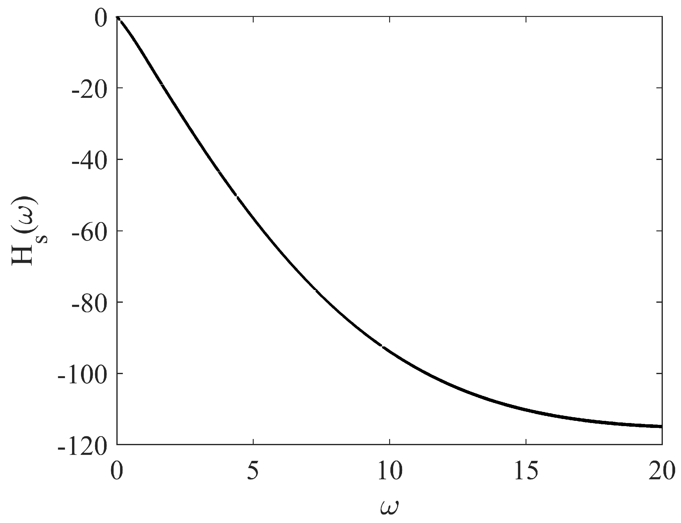
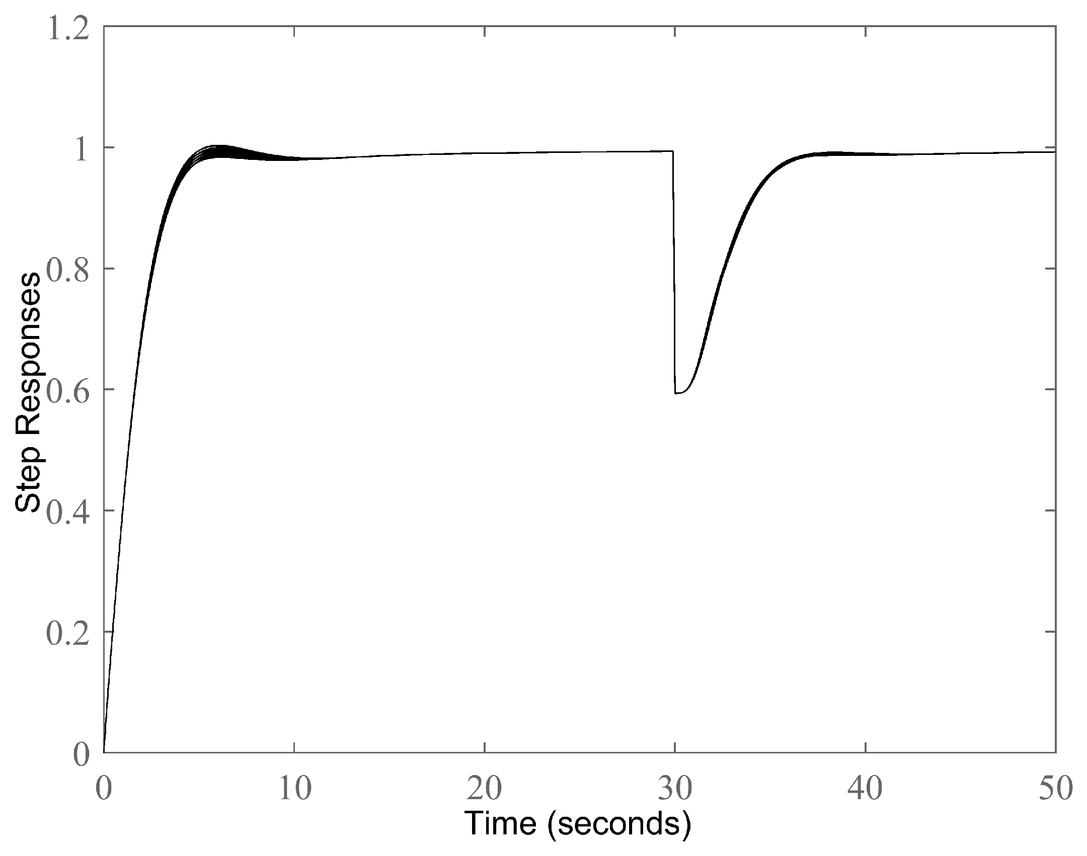
The Mikhailov’s plots corresponding to Δ 1 0 ( s ) (dotted line) and Δ 2 0 ( s ) (solid line) have been plotted in Figure 4 and Figure 5. Consequently, it can be inferred that the system’s stability is easily ascertained. At present, our sole task is to scrutinize the polarity of H ( ω ) pertaining to both controllers: namely, C 1 ( s ) in (26) or C 2 ( s ) in (28). Furthermore, in accordance with the controllers C 1 ( s ) and C 2 ( s ) presented in Equations (26) and (28), respectively, the corresponding H ( ω ) has been illustrated in Figure 6 and Figure 7, respectively. A comprehensive analysis of these figures suggests that the controller C 2 ( s ) fails to fulfill the critical condition H ( ω ) > 0 , which, as per Theorem 2, renders the system incapable of achieving robust stability. Conversely, the controller C 1 ( s ) effectively stabilizes the closed-loop control system. Remarkably, the outcomes obtained from the robust stability region portrayed in Figure 2 coincide with these results. Furthermore, to enhance the system’s disturbance rejection capability, a plot of H s ( ω ) has been generated for M s ( s ) = ( s + 1000 ) ( s + 30.67 ) ( s + 0.001 ) s 2 + 30.67 s + 247.3 in Figure 8. It can be observed from Figure 8 that H s ( ω ) < 0 , ensuring the preservation of robust performance. With regards to robust performance, we specifically opt for a controller that satisfies the inequality H S ( s ) < 0 : this selection criterion is motivated by the objective to attain robust performance. Figure 9 exhibits the step responses, which demonstrate an acceptable level of performance. Figure 10 shows a comparison of TID (26), PID (30), and FOPID (31) controllers for the nominal plant (19), based on the methods proposed in [41]. As shown in Figure 10, the TID has a better performance, in the sense of faster responses and smaller overshoots.
C P I D ( s ) = 2.12224 + 2.4679 s + 0.4563 s
C F O P I D ( s ) = 0.1112 + 0.0694 s 1.2 + 0.7 s

5. Conclusions

This paper presented a novel approach for obtaining the stabilizing region of TID controllers applicable to fractional-order interval plants. Initially, a pertinent theorem was introduced, to analyze the robust stability of a closed-loop system, which comprised a TID controller and an interval fractional-order plant. Based on the insights gained from Theorem 1, a practical algorithm was devised for computing the stabilizing region of TID controllers. An auxiliary function was proposed, to enhance the disturbance rejection control criteria. Finally, the effectiveness of the proposed approach was verified via the demonstration of two examples. It is important to acknowledge that the current discussion has not specifically addressed the matter of finding optimal TID controllers; therefore, future endeavors could involve exploring techniques to determine the optimal TID control or to calculate the stabilizing region for fractional TID controllers within fractional-order interval systems that incorporate an interval time delay. These aspects present potential avenues for further research and development in this field.

Author Contributions

Validation, S.Z.; Investigation, G.C.; Writing—review & editing, M.Z.M.; Funding acquisition, M.L.A. All authors have read and agreed to the published version of the manuscript.

Funding

This research was funded by the Deputyship for Research Innovation, Ministry of Education in Saudi Arabia through grant number 223202.

Data Availability Statement

Data are available upon request.

Acknowledgments

The authors extend their appreciation to the Deputyship for Research & Innovation, Ministry of Education in Saudi Arabia for funding this research work through the project number 223202.

Conflicts of Interest

The authors declare no conflict of interest.

References

  1. Hilfer, R. (Ed.) Applications of Fractional Calculus in Physics; World Scientific: Singapore, 2000. [Google Scholar]
  2. Dalir, M.; Bashour, M. Applications of fractional calculus. Appl. Math. Sci. 2010, 4, 1021–1032. [Google Scholar]
  3. Ortigueira, M.D. Fractional Calculus for Scientists and Engineers; Springer Science & Business Media: Berlin/Heidelberg, Germany, 2011; Volume 84. [Google Scholar]
  4. Tarasov, V.E. (Ed.) Handbook of Fractional Calculus with Applications; De Gruyter: Berlin, Germany, 2019; Volume 5. [Google Scholar]
  5. Ghorbani, M.; Tavakoli-Kakhki, M.; Tepljakov, A.; Petlenkov, E. Robust stability analysis of smith predictor based interval fractional-order control systems: A case study in level control process. IEEE/CAA J. Autom. Sin. 2022, 10, 762–780. [Google Scholar] [CrossRef]
  6. Ghorbani, M.; Tepljakov, A.; Petlenkov, E. Robust FOPID Stabilization for Smith Predictor Structures. In Proceedings of the 2022 IEEE 61st Conference on Decision and Control (CDC), Cancun, Mexico, 6–9 December 2022. [Google Scholar]
  7. Ghorbani, M. Robust stabilization criteria of a general form of fractional-order controllers for interval fractional-order plants with complex uncertain parameters. ISA Trans. 2022, 129, 140–151. [Google Scholar] [CrossRef] [PubMed]
  8. Asadi, M.; Farnam, A.; Nazifi, H.; Roozbehani, S.; Crevecoeur, G. Robust Stability Analysis of Unstable Second Order Plus Time-Delay (SOPTD) Plant by Fractional-Order Proportional Integral (FOPI) Controllers. Mathematics 2022, 10, 567. [Google Scholar] [CrossRef]
  9. Pachauri, N.; Suresh, V.; Kantipudi, M.P.; Alkanhel, R.; Abdallah, H.A. Multi-Drug Scheduling for Chemotherapy Using Fractional Order Internal Model Controller. Mathematics 2023, 11, 1779. [Google Scholar] [CrossRef]
  10. Chávez-Vázquez, S.; Gómez-Aguilar, J.F.; Lavín-Delgado, J.E.; Escobar-Jiménez, R.F.; Olivares-Peregrino, V.H. Applications of fractional operators in robotics: A review. J. Intell. Robot. Syst. 2022, 104, 63. [Google Scholar] [CrossRef]
  11. Warrier, P.; Shah, P. Fractional order control of power electronic converters in industrial drives and renewable energy systems: A review. IEEE Access 2021, 9, 58982–59009. [Google Scholar] [CrossRef]
  12. Shah, P.; Agashe, S. Review of fractional PID controller. Mechatronics 2016, 38, 29–41. [Google Scholar] [CrossRef]
  13. Goharimanesh, M.; Lashkaripour, A.; Mehrizi, A.A. Fractional order PID controller for diabetes patients. J. Comput. Appl. Mech. 2015, 46, 69–76. [Google Scholar]
  14. Kumar, V.; Rana, K.P.S.; Kumar, J.; Mishra, P. Self-tuned robust fractional order fuzzy PD controller for uncertain and nonlinear active suspension system. Neural Comput. Appl. 2018, 30, 1827–1843. [Google Scholar] [CrossRef]
  15. Bhattacharyya, S.P.; Keel, L.H. Robust control: The parametric approach. In Advances in Control Education 1994; Elsevier: Pergamon, Turkey, 1995; pp. 49–52. [Google Scholar]
  16. Ghorbani, M.; Tavakoli-Kakhki, M. Robust stability analysis of uncertain incommensurate fractional order quasi-polynomials in the presence of interval fractional orders and interval coefficients. Trans. Inst. Meas. Control. 2021, 43, 1117–1125. [Google Scholar] [CrossRef]
  17. Ghorbani, M.; Tavakoli-Kakhki, M.; Estarami, A.A. Robust FOPID stabilization of retarded type fractional order plants with interval uncertainties and interval time delay. J. Frankl. Inst. 2019, 356, 9302–9329. [Google Scholar] [CrossRef]
  18. Zheng, S.; Li, W. Robust stabilization of fractional-order plant with general interval uncertainties based on a graphical method. Int. J. Robust Nonlinear Control. 2018, 28, 1672–1692. [Google Scholar] [CrossRef]
  19. Badri, P.; Sojoodi, M. LMI-based robust stability and stabilization analysis of fractional-order interval systems with time-varying delay. Int. J. Gen. Syst. 2022, 51, 1–26. [Google Scholar] [CrossRef]
  20. Di, Y.; Zhang, J.-X.; Zhang, X. Robust stabilization of descriptor fractional-order interval systems with uncertain derivative matrices. Appl. Math. Comput. 2023, 453, 128076. [Google Scholar] [CrossRef]
  21. Casagrande, D.; Krajewski, W.; Viaro, U. On the robust stability of commensurate fractional-order systems. J. Frankl. Inst. 2022, 359, 5559–5574. [Google Scholar] [CrossRef]
  22. Zheng, S. Robust stability of fractional order system with general interval uncertainties. Syst. Control. Lett. 2017, 99, 1–8. [Google Scholar] [CrossRef]
  23. Moornani, K.A.; Haeri, M. On robust stability of LTI fractional-order delay systems of retarded and neutral type. Automatica 2010, 46, 362–368. [Google Scholar] [CrossRef]
  24. Moornani, K.A.; Haeri, M. On robust stability of linear time invariant fractional-order systems with real parametric uncertainties. ISA Trans. 2009, 48, 484–490. [Google Scholar] [CrossRef]
  25. Moornani, K.A.; Haeri, M. Robust stability testing function and Kharitonov-like theorem for fractional order interval systems. IET Control. Theory Appl. 2010, 4, 2097–2108. [Google Scholar] [CrossRef]
  26. Moornani, K.A.; Haeri, M. Robustness in fractional proportional–integral–derivative-based closed-loop systems. IET Control. Theory Appl. 2010, 4, 1933–1944. [Google Scholar] [CrossRef]
  27. Ghorbani, M.; Rezaei, H.; Tepljakov, A.; Petlenkov, E. Robust stability testing function for a complex interval family of fractional-order polynomials. J. Frankl. Inst. 2022, 17, 10038–10057. [Google Scholar] [CrossRef]
  28. Ghorbani, M.; Tavakoli-Kakhki, M.; Tepljakov, A.; Petlenkov, E.; Farnam, A.; Crevecoeu, G. Robust stability analysis of interval fractional-order plants with interval time delay and general form of fractional-order controllers. IEEE Control. Syst. Lett. 2021, 6, 1268–1273. [Google Scholar] [CrossRef]
  29. Luo, Y.; Chen, Y. Stabilizing and robust FOPI controller synthesis for first order plus time delay systems. In Proceedings of the 2011 50th IEEE Conference on Decision and Control and European Control Conference, Orlando, FL, USA, 12–15 December 2011. [Google Scholar]
  30. Luo, Y.; Chen, Y. Stabilizing and robust fractional order PI controller synthesis for first order plus time delay systems. Automatica 2012, 48, 2159–2167. [Google Scholar] [CrossRef]
  31. Hamamci, S.E. An algorithm for stabilization of fractional-order time delay systems using fractional-order PID controllers. IEEE Trans. Autom. Control. 2007, 52, 1964–1969. [Google Scholar] [CrossRef]
  32. Hamamci, S.E. Stabilization using fractional-order PI and PID controllers. Nonlinear Dynamics 2008, 51, 329–343. [Google Scholar] [CrossRef]
  33. Zheng, S.; Tang, X.; Song, B. A graphical tuning method of fractional order proportional integral derivative controllers for interval fractional order plant. J. Process. Control. 2014, 24, 1691–1709. [Google Scholar] [CrossRef]
  34. Singh, K.; Amir, M.; Ahmad, F.; Khan, M.A. An integral tilt derivative control strategy for frequency control in multi microgrid system. IEEE Syst. J. 2020, 15, 1477–1488. [Google Scholar] [CrossRef]
  35. Ahmed, M.; Magdy, G.; Khamies, M.; Kamel, S. Modified TID controller for load frequency control of a two-area interconnected diverse-unit power system. Int. J. Electr. Power Energy Syst. 2022, 135, 107528. [Google Scholar] [CrossRef]
  36. Lu, C.; Tang, R.; Chen, Y.; Li, C. Robust tilt-integral-derivative controller synthesis for first-order plus time delay and higher-order systems. Int. J. Robust Nonlinear Control. 2023, 33, 1566–1592. [Google Scholar] [CrossRef]
  37. Tan, N.; Özgüven, Ö.F.; Özyetkin, M.M. Robust stability analysis of fractional order interval polynomials. ISA Trans. 2009, 48, 166–172. [Google Scholar] [CrossRef] [PubMed]
  38. Levine, W.S. The Control Handbook (Three Volume Set); CRC Press: Boca Raton, FL, USA, 2018. [Google Scholar]
  39. Brown, J.W.; Churchill, R.V. Complex Variables and Applications; McGraw-Hill: New York, NY, USA, 2009. [Google Scholar]
  40. Busłowicz, M. Stability of linear continuous-time fractional order systems with delays of the retarded type. Bull. Pol. Acad. Sci. Tech. Sci. 2008, 56, 319–324. [Google Scholar]
  41. Valério, D.; Da Costa, J. Tuning of fractional PID controllers with Ziegler–Nichols-type rules. Signal Process. 2006, 86, 2771–2784. [Google Scholar] [CrossRef]
Figure 1. Closed-loop fractional control system.
Mathematics 11 02763 g001
Figure 2. Robust stability region of TID controllers.
Mathematics 11 02763 g002
Figure 3. Mikhailov’s plot for ψ ( s ) = Δ 0 ( s ) ( s + 1 ) 4 .
Mathematics 11 02763 g003
Figure 4. Mikhailov’s plot for ψ ( s ) = Δ 1 0 ( s ) ( s + 1 ) 4 .
Mathematics 11 02763 g004
Figure 5. Mikhailov’s plot for ψ ( s ) = Δ 2 0 ( s ) ( s + 1 ) 4 .
Mathematics 11 02763 g005
Figure 6. Curve of H ( ω ) corresponding to C 1 ( s ) .
Mathematics 11 02763 g006
Figure 7. Curve of H ( ω ) corresponding to C 2 ( s ) .
Mathematics 11 02763 g007
Figure 8. Curve of H s ( ω ) corresponding to C 1 ( s ) .
Mathematics 11 02763 g008
Figure 9. Step responses corresponding to C 1 ( s ) .
Mathematics 11 02763 g009
Figure 10. Step responses corresponding to FOPID (blue color), PID (black color), and TID (red color).
Mathematics 11 02763 g010
Disclaimer/Publisher’s Note: The statements, opinions and data contained in all publications are solely those of the individual author(s) and contributor(s) and not of MDPI and/or the editor(s). MDPI and/or the editor(s) disclaim responsibility for any injury to people or property resulting from any ideas, methods, instructions or products referred to in the content.