Article

Hydro-Mechanical Coupling of Cement-Based Slurry Grouting in Saturated Geomaterials

School of Water Conservancy and Civil Engineering, Zhengzhou University, Zhengzhou 450001, China
*
Author to whom correspondence should be addressed.
Mathematics 2023, 11(13), 2877; https://doi.org/10.3390/math11132877
Submission received: 17 May 2023 / Revised: 18 June 2023 / Accepted: 24 June 2023 / Published: 27 June 2023

Abstract

:
A mathematical model is proposed to simulate the fully hydro-mechanical coupling of two-phase cement-based slurry migration in saturated deformable geomaterials from microscopic to macroscopic scale. The mass conservation equations and the momentum balance equations for cement-based slurry and geomaterials are derived based on the thermodynamically constrained averaging theory (TCAT). The Galerkin discretization of the governing equations of hydro-mechanical coupling are developed by the isogeometric analysis (IGA) integrated with the Bézier extraction operator, and the numerical calculation is implemented with the generalized backward Euler method. The presented modeling is verified by comparison of the numerical calculation with the experimental tests, and the pore fluid pressure of the stratum and the slurry concentration of cement-based slurry migration in saturated deformable geomaterials are discussed. The modeling presented provides an effective alternative method to simulate cement-based slurry migration and explore isothermal multiphase coupled problems.

1. Introduction

Slurry grouting is a widely adopted technology in geotechnical engineering for reducing the permeability or/and improving the mechanical characteristics of geomaterials such as soils or rocks. Cement-based slurries are regarded as a suspension of cement particles with additional components such as bentonite and stabilizing and dispersing agents in water, which have been widely used in grouting in view of their lower cost and environmental pollution compared to chemical slurries.
The geomaterials are porous media, and the cement-based slurries are a two-phase fluid. Therefore, the essence of cement-based slurry grouting in geomaterials is that the water and suspended solid particles within the slurries are transported in porous media. When the cement-based slurry is grouted into the geomaterials, the migration of suspended slurry particles takes place by the advection, diffusion, and dispersion. A fraction of the suspended slurry particles deposit and accumulate on the surface of the solid skeleton of geomaterials, which blocks the transport channels within the geomaterials and gradually terminates the further permeation of the cement-based slurry. The permeability of the geomaterials is significantly reduced; more seriously, the increasing pore fluid pressure leads to the deformation of the solid skeleton or even to the failure of the injected geomaterials.
With the aim of further clarifying the migration laws and improving the effectiveness of the cement-based slurry grouting in geomaterials, the researchers performed mostly one-dimensional cement-based slurry grouting experiments under certain conditions such as grouting pressure, grouting rate, and grouting concentration in the laboratory [1,2,3]. However, three-dimensional or in situ tests are more suitable for evaluating cement-based slurry grouting implemented in fieldworks [4]. Scholars have proposed many numerical analysis [5,6,7,8] or analytical methods [9,10,11,12,13,14,15] to explore the migration mechanism of cement-based slurry grouting in geomaterials. The common disadvantage of these models is that they cannot reflect the hydro-mechanical dynamic coupling between the force acting on the solid skeleton of geomaterials and the migration of suspended slurry particles.
As mentioned above, the cement-based slurry grouting in geomaterials is a mechanics problem of multiphase porous media, which is usually analyzed by the hybrid mixture theory (HMT) [16]. However, the thermodynamics postulated in the HMT loses the connection between the microscale and macroscale. Thus, the thermodynamically constrained averaging theory (TCAT) [17] was developed to formulate the macroscale mechanical models for multiphase porous media consistent with microscale thermodynamics and physical properties using the averaging theories. The TCAT approach has been introduced primarily in deriving hydrological models such as single or multiphase fluid flow and species or heat transportation in porous media [17,18,19,20] and revealing multiphysics problems such as hygro-thermal coupling in concrete [16] and the growth or necrosis of biological tissues [21,22] involving diffusion, advection, dispersion, adsorption, chemical reactions, phase changes, temperature changes, and other phenomenon.
Moreover, numerical methods are usually used to solve the governing equations for mechanics problems of multiphase porous media such as finite element method (FEM) [5,6,7]. However, FEM mesh geometry replaces real geometry with piecewise polynomial approximation, and mesh refinement in local scale and high computational cost are required for achieving high-precision analysis results. Fortunately, isogeometric analysis (IGA) presented by Hughes et al. [23] changes this situation using the same basis functions such as B-splines, and NURBS, or T-splines employed in CAD to express the real geometry of objects, thereby eliminating the mesh in FEM, realizing direct interaction between numerical analysis and CAD, simplifying the refinement process, reducing the computational costs, and improving the solution accuracy. The IGA has been widely used to simulate various mechanics and engineering problems, for example, structural analysis [24], fluid mechanics [25], solid mechanics [26], and the THM-coupled process in porous media [27,28,29,30]. Recently, Borden et al. [31] and Scott et al. [32] proposed that the basis functions for B-splines, NURBS, and T-splines in IGA consisted of the linear Bernstein polynomials using a Bézier extraction operator; this transformation enables the element structure of IGA to be the same as the element structure of FEM, and the IGA procedure is implemented by FEM program. Therefore, the Bézier extraction operator arouses particular interest in geo-mechanical simulation [33,34,35].
This study presents mathematical modeling that can efficiently simulate the hydro-mechanical fully dynamic coupled migration of two-phase cement-based slurry grouting in saturated deformable geomaterials from the microscale to the macroscale. The proposed mathematical modeling uses the thermodynamically constrained averaging theory (TCAT) to establish the governing equations for two-phase cement-based slurry and geomaterials, the IGA with Bézier extraction is applied for Galerkin discretization of the governing equations, and the solution is implemented with the generalized backward Euler method.
The layout of this manuscript is arranged as follows. The derivation of the mass conservation equations, momentum balance equations and supplementary equations is presented in Section 2. The Bézier extraction operator is introduced, and the discretization for the governing equations and the solving process are given in Section 3. The accuracy of the proposed modeling was verified by comparison with a cement-based slurry grouting experiment, and the pore fluid pressure and the slurry concentration are discussed in Section 4. The conclusions are expressed in Section 5.

2. Governing Equations for Cement-Based Slurry Grouting

The macroscopic mass conservation equations and momentum balance equations for simulation two-phase cement-based slurry grouting in saturated deformable geomaterials with the TCAT procedure are presented.

2.1. Mass Conservation Equations

The solid phase of geomaterials s comprises the solid skeleton with mass fraction ω ss and the growing slurry particles attached to the surface of solid skeleton with mass fraction ω as . The sum of the mass fractions of two constituents of solid phase is equal to 1.
ω as + ω ss = 1
Assuming that the diffusion between the two constituents of the solid phase does not occur, based on the basic mass conservation principles of TCAT theory [17], the macroscopic mass conservation equations for the slurry particles attached to the surface of solid skeleton and the solid skeleton read, respectively, are
ϕ s ρ s ω as t + ϕ s ρ s ω as ν s - M f as = 0
ϕ s ρ s ω ss t + ϕ s ρ s ω ss ν s = 0
where ϕ s is the volume fraction of solid phase, ρ s is the density of solid phase, ν s is the velocity of solid phase, and M f as is the sum mass transport of slurry particles attached to the surface of solid skeleton.
Combine Equations (2) and (3) to yield the macroscopic mass conservation equation for the solid phase of geomaterials:
ϕ s ρ s t + ϕ s ρ s ν s - M f as = 0
Expand Equation (2) using the product rule, then substitute into Equation (4) to achieve an alternative mass conservation equation for the slurry particles attached to the surface of solid skeleton:
ϕ s ρ s ω as t + ϕ s ρ s ν s ω as - 1 - ω as M f as = 0
The slurry phase f comprises the water in slurry with mass fraction ω wf and the decreasing suspended slurry particles with mass fraction ω sf . The sum of the mass fractions of two constituents of slurry phase is equal to 1.
ω wf + ω sf = 1
The macroscopic mass conservation equations for the water solvent and the suspended slurry particles within slurry are, respectively
ϕ f ρ f ω wf t + ϕ f ρ f ω wf ν wf = 0
ϕ f ρ f ω sf t + ϕ f ρ f ω sf ν f + ϕ f ρ f ω sf u sf ¯ ¯ + M sf s = 0
where ϕ f is the volume fraction of slurry phase in geomaterials, ρ f is the density of slurry phase, ν f is the velocity of slurry phase, ν wf is the velocity of water within slurry, M sf s is the sum mass transport of suspended slurry particles sf attached to the solid skeleton, and u sf ¯ ¯ is the diffusion velocity of suspended slurry particles sf .
Similar to the solid phase of geomaterials, the summation of Equations (7) and (8) sets the macroscopic mass conservation equation for the slurry phase as
ϕ f ρ f t + ϕ f ρ f ν f + M sf s = 0
Expanding Equation (8) with the product rule, then substituting it into Equation (9), obtains an alternative equation for the suspended slurry particles in slurry phase:
ϕ f ρ f ω sf t + ϕ f ρ f ν f ω sf + ϕ f ρ f ω sf u sf ¯ ¯ + 1 ω sf M sf s = 0
Obviously, M sf s = M f as = M sf as .

2.2. Momentum Balance Equations

For the slow-flowing slurry in geomaterials, the momentum due to inertia is negligible [1,9,10,11,12]. Meanwhile, the momentum exchange owing to the mass transfer of slurry to solid phase is also considered small and is neglected, having the same order of magnitude as the inertial momentum terms. The basic momentum balance equation for an arbitrary phase α in the TCAT framework simplifies to [17,22]
ϕ α t α ϕ α ρ α g α κ c α Τ κ α = 0
where g α is the body force of phase α , t α is the stress tensor of phase α , and κ c α Τ κ α is the interaction force between phase α and adjacent interface of phase κ .
The stress tensor of slurry phase f is [17,22]
t f = p f Ι
where p f is the slurry pressure and Ι is the unit tensor.
The momentum balance equation, Equation (10), for the slurry phase changes to
ϕ f p f ρ f g f + R f ν f ν s = 0
where R f is the resistance to slurry flow in geomaterials.
Let K f = k μ = ε f 2 R f ; Equation (13) is expressed as a form of Darcy’ law
K f p f ρ f g f + ϕ f ν f ν s = 0
in which k is the intrinsic permeability of geomaterials, and μ is the dynamic viscosity of slurry.
The momentum balance equation, Equation (11), for the solid phase changes to
ϕ s τ s α p f Ι + ϕ s ρ s g s + ϕ f ρ f g f = 0
where α = 1 K T K S , K T is the bulk modulus of the solid phase, K S is the averaged bulk modulus of the solid particles, for incompressible solid α = 1 , ϕ s τ s is the effective stress tensor, ϕ s τ s = D s ε e s = D s ε s ε p s , D s is the constitutive matrix of the solid phase, ε e s is the elastic strain of solid phase, ε s is the total strain, and ε p s is the plastic strain.

2.3. The Final Equations for Grouting

The macroscopic mass balance equation of slurry particles attached to the surface of solid skeleton is
1 ϕ f ρ s ω as t + 1 ϕ f ε s ρ s ν s ω as = 1 - ω as M sf as
The diffusive velocity is approximately calculated using Fick’s law
ω sf u sf ¯ ¯ = D sf ¯ ω sf
The macroscopic mass balance equation of suspended slurry particles in slurry phase transforms to
ϕ f ρ f ω sf t ( ϕ f ρ f D sf ¯ ω sf ) + ϕ f ρ f ν f ω sf = 1 ω sf M sf as
where D sf ¯ is the effective dispersion tensor.
Combine Equations (4) and (9), then introduce Equation (14) to obtain
1 ϕ f ρ s D s ρ s Dt + ϕ f ρ f D s ρ f Dt + ν s 1 ρ f ρ f K f p f ρ f g + 1 ρ f 1 ρ s M sf as = 0
making   β s = 1 ρ s D ρ s D p f ,   β f = 1 ρ f D ρ f D p f
where β s , β f are the compressibility of the solid phase and the slurry phase, respectively.
Substitute the state equations, Equation (20), into Equation (19) to achieve
1 ϕ f β s + ϕ f β f D s p f Dt + ν s 1 ρ f ρ f K f p f ρ f g + 1 ρ f 1 ρ s M sf as = 0
The velocity of the solid phase is very slow, and the slurry pressure will spread quickly [17], so
p f t ν s p f
Based on this approximation, the partial time derivative replaces the material derivative in Equation (21) and it changes to
1 ϕ f β s + ϕ f β f p f t + u s t 1 ρ f ρ f K f p f ρ f g + 1 ρ f 1 ρ s M sf as = 0
Considering only that the solid phase is elastic, the momentum balance equation for solid phase is
D e s ε e s p f Ι + 1 ϕ f ρ s g + ϕ f ρ f g = 0
The iterations within each time step are adapted to keep the coupling between the governing equations in the solving process of the governing equations for two-phase cement-based slurry grouting. Two computational steps are used in each coupling iteration: the first is applied to obtain the mass fraction of suspended slurry particles ω sf and the mass fraction of slurry particles attached to the solid skeleton ω as , the second to calculate the slurry pressure ρ f and the displacement of the solid phase U s .
For each coupling iteration, firstly, solve Equation (16) to achieve the mass fraction of slurry particles attached to the solid skeleton ω as , and solve Equation (18) to obtain the mass fraction of the suspended slurry particles ω sf , then update the mass transport of the slurry particles attached to the surface of the solid skeleton M sf s , the density of slurry ρ f and the density of the solid phase ρ s ; finally, combine Equations (23) and (24) to solve for the fluid pressure p f and the displacement vector of solid phase U s . The calculation procedure moves forward when the convergence is achieved within a time step.

3. Discretization and Solving

3.1. Bézier Extraction Operator

The essential difference between FEM and IGA is the geometric topology, the real geometry is determined by the control points and the basis functions in IGA; however, the mesh geometry replaces real geometry in FEM. The Bézier extraction operator employs piecewise C0 Bernstein polynomial basis functions so that the B-splines or NURBS or T-splines used in IGA are represented in FEM. The univariate Bézier extraction operator is calculated by repeating all the internal knots of a non-decreasing knot vector until the multiplicity is equal to the polynomial order of basis functions, which means the control points and the basis functions do not determine the Bézier extraction operator that decomposes the global basis functions in traditional IGA to the local mesh element.
The basis functions for B-spline with Bézier extraction can be realized locally for each element with the equation [31]
N e ξ = C e B e ξ
where C e is the local Bézier extraction operator matrix and the order of matrix is p + 1 × p + 1 ; B e ξ is the Bernstein polynomial basis functions and N e ξ is the basis function for B-spline with local Bézier extraction.
The basis functions for NURBS with Bézier extraction can be determined in local mesh element as
R e ξ = 1 W b ξ W e C e B e ξ
where W e is the diagonal matrix of local NURBS weights, W b is the weight function with Bézier extraction, W b ξ = w e T C e B e ξ , w e is the local NURBS weights, and R e ξ is the basis function for NURBS with local Bézier extraction.
The local two-dimensional and three-dimensional Bézier extraction operator, respectively, are calculated by
C e = C η j C ς k
C e = C ε i C η j C ς k
where C ς k , C η j and C ε i are the elements of the local univariate Bézier extraction operator of ς , η and ε direction, respectively, i = 1 , 2 , , n , j = 1 , 2 , , m , k = 1 , 2 , , l , e = n × m × l .
Thus, the basis functions for the element are similar to that in traditional FEM, which results in the conformation of the element stiffness matrix being almost the same as traditional FEM.

3.2. Discretization for Governing Equations

Suppose Ω and Γ show the domain and its continuous boundary of representative elementary volume (REV) for the object, respectively. The boundary conditions on Γ include Dirichlet conditions on Γ D and Neumann conditions on Γ N , which indicates Γ = Γ D Γ N .
The approximate solutions of field variables are expressed at a local element based on Bézier extraction as
U s e = i = 1 N e N i U U i es p f e = i = 1 N e N i p p i ef
ω as e = i = 1 Ne N i ω s ω i eas ω sf e = i = 1 Ne N i ω f ω i esf
where Ne is the number of control points at each local element; N i U , N i p , N i ω s and N i ω f are the basis functions for the displacement of solid phase, fluid pressure, mass fraction of slurry particles attached to solid skeleton and mass fraction of suspended slurry particles at each control point i of local element, respectively; and U i es , p i ef , ω i eas and ω i esf are the corresponding values, respectively.
The strain at each control point of local element is obtained by
ε s e = i = 1 Ne N i ε U i es
where N i ε = N i U .
For a two-dimensional situation,
U s e = u s v s T     U i es = u i s v i s T
N i ε = N i U x 0 N i U y 0 N i U y N i U x T
For a three-dimensional spatial problem,
U s e = u se v se w se T     U i es = u i s v i s w i s T
N i ε = N i U x 0 0 N i U y N i U z 0 0 N i U y 0 N i U x 0 N i U z 0 0 N i U z 0 N i U x N i U y T
The weak form of the linear momentum balance equation is achieved by integrating the result function of Equation (24) and multiplying an arbitrary test function ϕ u over the domain of local element and is written as
Ω e δ ϕ u D s ε e s p f Ι + 1 ϕ f ρ s g + ϕ f ρ f g d Ω e = Γ e t r δ ϕ u d Γ e
where t r is the boundary traction on Γ N .
Take the basis functions for the displacement N U as the arbitrary test function ϕ u , and then substitute this into the equation to result in Galerkin discretization:
M 1 U es + M 2 p ef = F u
where
M 1 = Ω e N U Τ D e N U d Ω e
M 2 = Ω e N U Τ Ι N p d Ω e
F u = Γ e N U Τ t r d Γ e Ω e N U Τ 1 ϕ f ρ s g + ϕ f ρ f g d Ω e
The weak form of Equation (23) is derived by introducing an arbitrary function ϕ p and adopting a similar procedure, shown as
Ω e δ ϕ p 1 ϕ f β s + ϕ f β f p f t + d U s dt 1 ρ f ρ f K f p f ρ f g + 1 ρ f 1 ρ s M sf as d Ω e = Γ e q f K f δ ϕ p d Γ e
where q f is the slurry flux on Γ N .
Take the basis functions for fluid pressure N P as the arbitrary test function ϕ p , the Galerkin discretization form of Equation (23) is given as
M 3 p ef · + M 4 U es · + M 5 p ef = F f
where
M 3 = Ω e N p Τ 1 ϕ f β s + ϕ f β f N P d Ω e
M 4 = Ω e N p Τ N U d Ω e
M 5 = Ω e N p Τ ρ f ρ f K f N P d Ω e
F f = Γ e N p Τ q f K f d Γ e Ω e N p Τ 1 ρ f ρ f K f ρ f g 1 ρ f 1 ρ s M sf as d Ω e
Using an arbitrary function ϕ sf and adopting the integrating procedure, the weak form of Equation (16) is defined as
Ω e δ ϕ sf ϕ f ρ f ω sf t ( ϕ f ρ f D sf ¯ ω sf ) + ϕ f ρ f ν f ω sf + 1 ω sf M sf as d Ω e = Γ e q sf ρ sf δ ϕ sf d Γ e
where q sf is the flux of suspended particles with slurry on Γ N .
The Galerkin discretization form of Equation (18) is derived by the basis functions for the mass fraction of suspended slurry particles N ω f replacing the arbitrary function ϕ sf :
M 6 ω esf · + M 7 ω esf = F sf
where
M 6 = Ω e N ω fT ϕ f ρ f N ω f d Ω e
M 7 = Ω e N ω fT ϕ f ρ f ν f N ω f ( ϕ f ρ f D sf N ω f ) N ω f M sf as d Ω e
F sf = Γ e N ω fT q sf ρ sf d Γ e Ω e N ω fT M sf as d Ω e
Using an arbitrary function ϕ a s and adopting the integrating procedure, the weak form of Equation (15) is shown:
Ω e δ ϕ as 1 ϕ f ρ s ω as t + 1 ϕ f ε s ρ s ν s ω as 1 - ω as M sf as d Ω e = Γ e q as ρ as δ ϕ as d Γ e
where q as is the flux of suspended particles attached to the solid skeleton on Γ N .
The Galerkin discretization form of Equation (16) is written as
M 8 ω e α s · + M 9 ω e α s = F as
where
M 8 = Ω e N ω s Τ 1 ϕ f ρ s N ω s d Ω e
M 9 = Ω e N ω s Τ 1 ϕ f ρ s ν s N ω s + N ω s M sf as d Ω e
F as = Γ e N ω s Τ q as ρ as d Γ e + Ω e N ω s Τ M sf as d Ω e
Summarize the Equations (31), (33), (35) and (37) into the coupled matrix
0 0 0 0 M 4 M 3 0 0 0 0 M 6 0 0 0 0 M 8 U es · p ef · ω esf · ω e α s · + M 1 M 2 0 0 0 M 5 0 0 0 0 M 7 0 0 0 0 M 9 U es p ef ω esf ω e α s = F u F f F sf F as
Equation (33) can simplify to
C X t + Κ X = F
where X = u p f ω s f ω α s is the unknown solution vector at each control point.

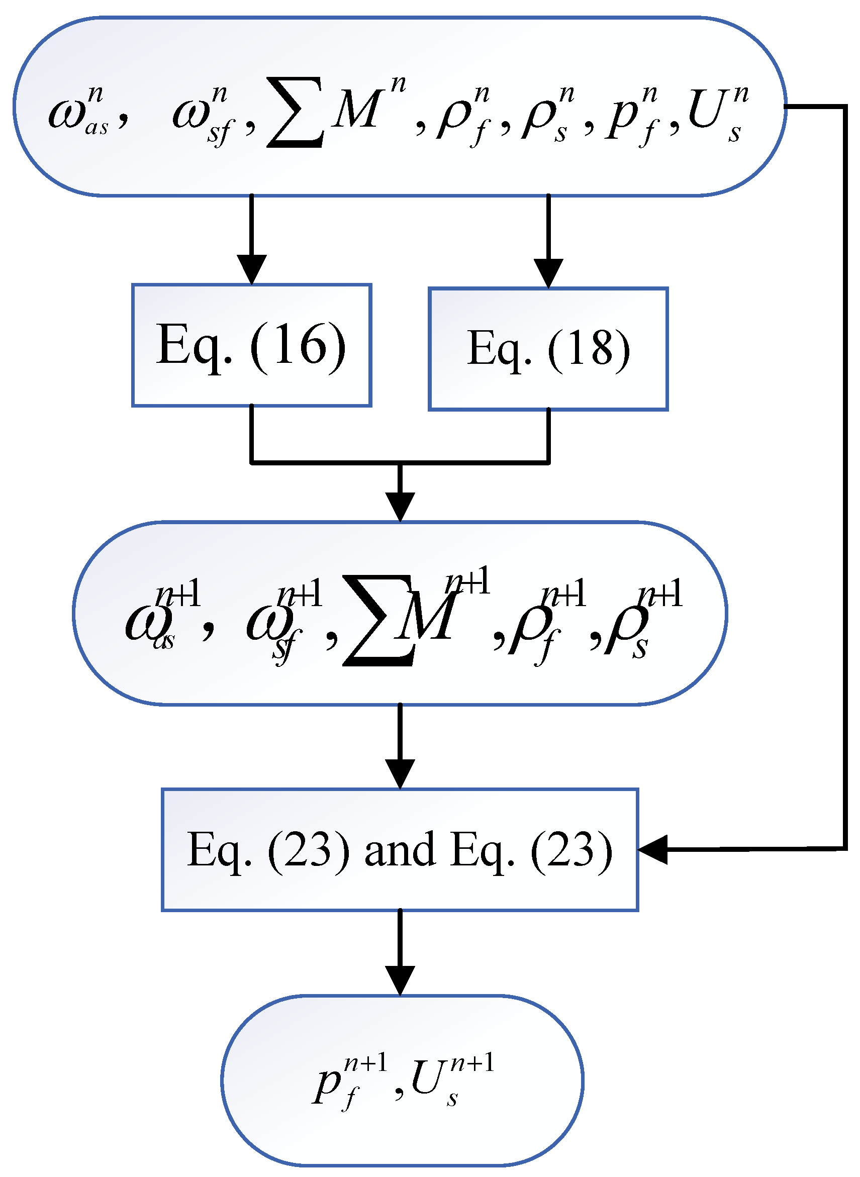
3.3. Solving Implementation

The change in rate of the unknown solution vector X is approximated with the backward Euler method and written as
X t n + 1 = X n + 1 X n t n + 1 t n
The coupled matrix Equation (39) at time step t n + 1 is given as
C X t n + 1 + Κ X n + 1 = F n + 1
Substitute Equation (40) into Equation (41) to obtain
t n + 1 t n K + C n + 1 X n + ! = C n + 1 X n + t n + 1 t n F n + 1
The residual R of Equation (39) at time step t n + 1 is [34,36]
R n + 1 = Δ t K + C n + 1 X n + ! C n + 1 X n + Δ t F n + 1
The increment of the unknown solution vector Δ X n + 1 i + 1 is calculated using the Newton–Raphson iteration scheme [36]
R X n + 1 i Δ X n + 1 i + 1 R n + 1 i
where i is the iteration number, n is the time step, and R X is the Jacobian matrix.
Update the unknown solution vector X at time step t n + 1 incrementally after each iteration with
X n + 1 i + 1 = X n + 1 i + Δ X n + 1 i + 1

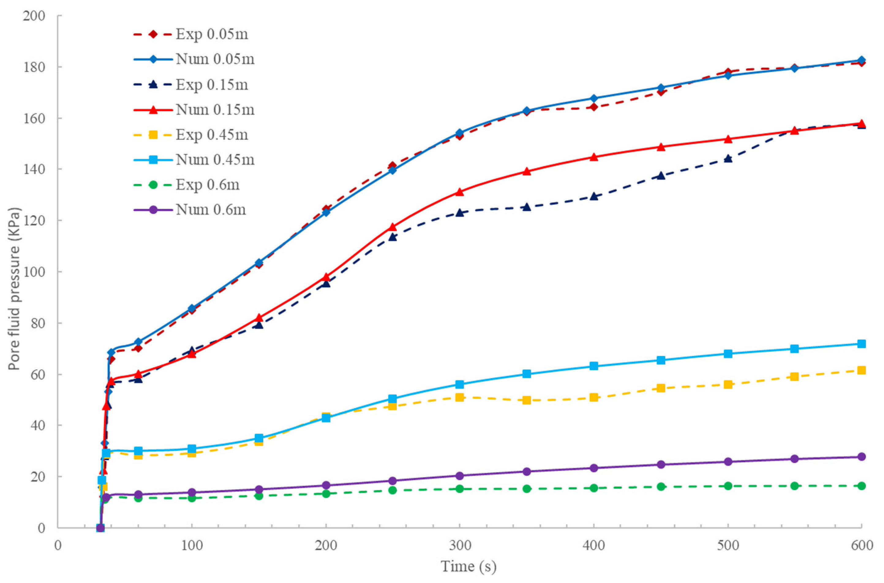
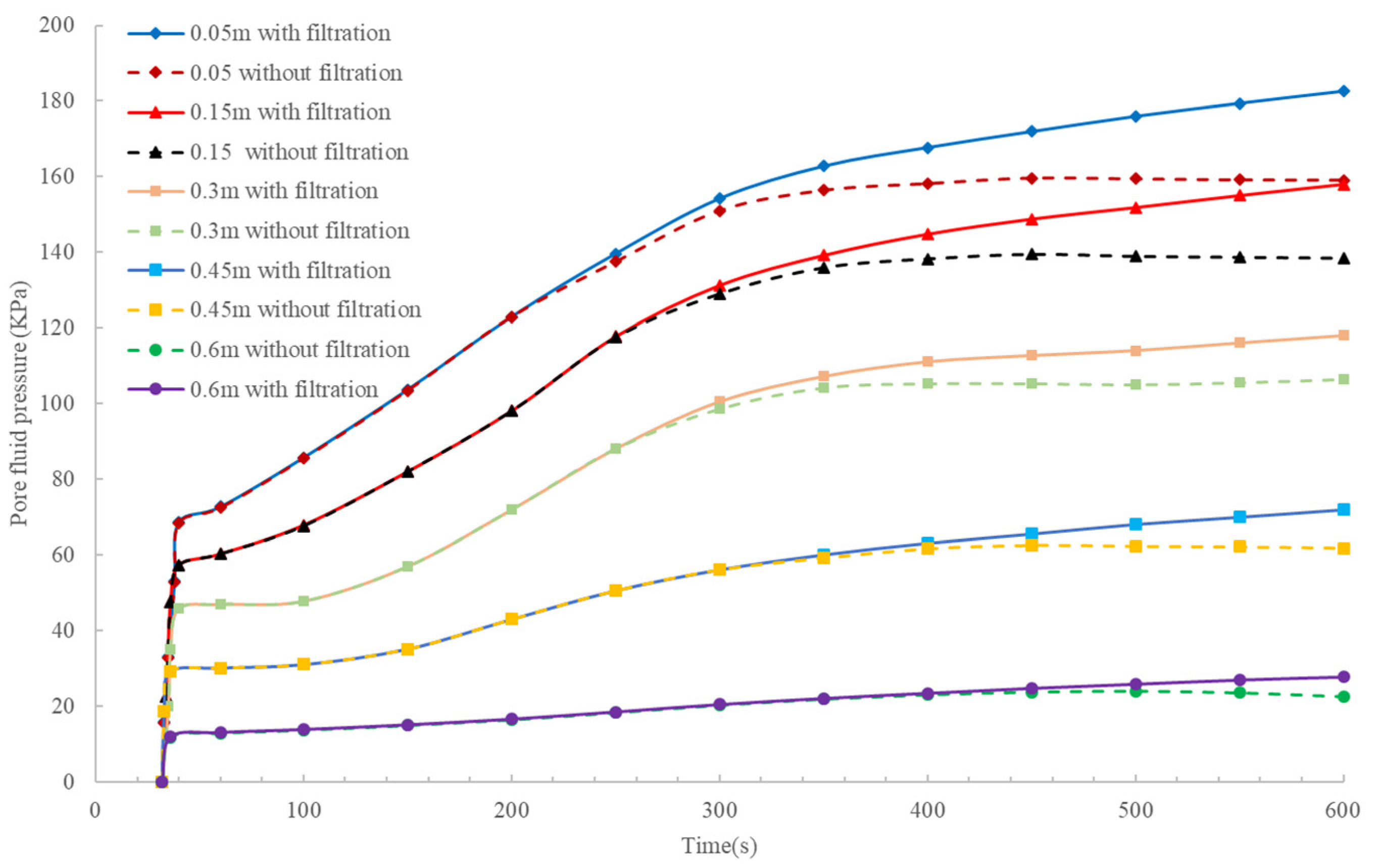
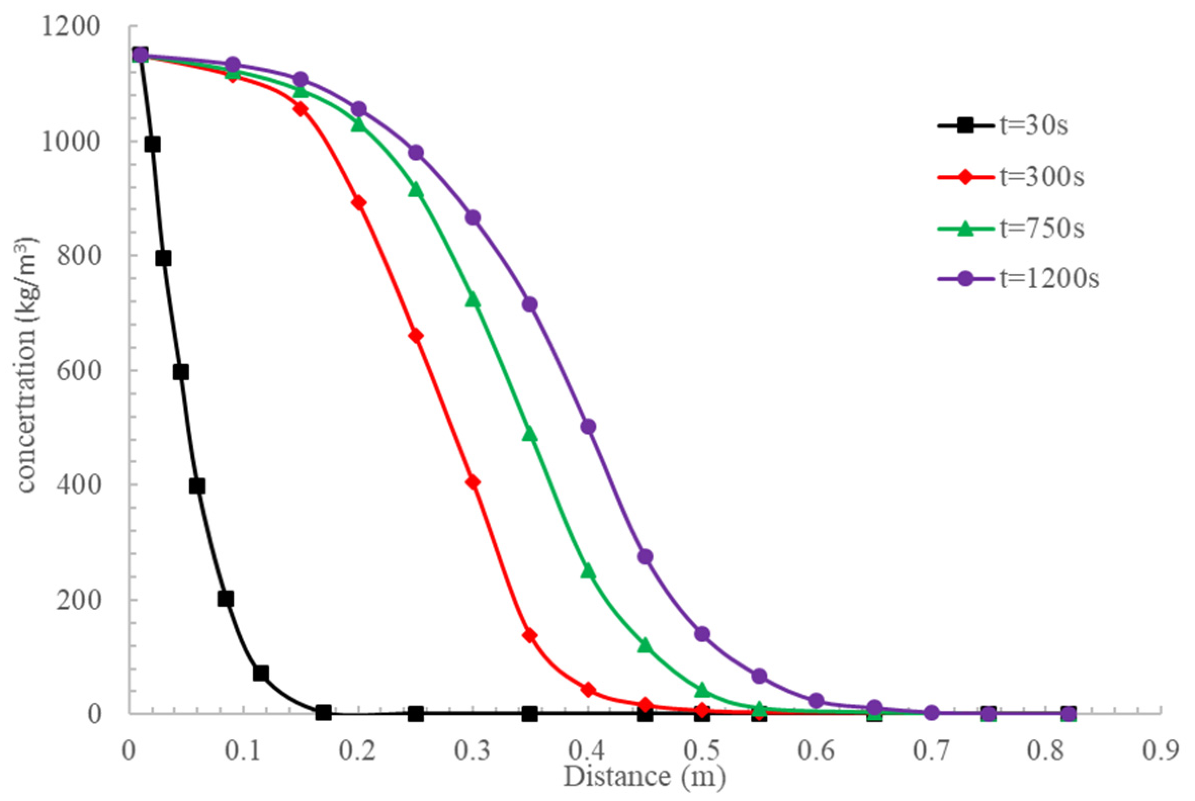
4. Validation and Discussion

The performance of the proposed model is investigated through a one-dimensional injection experiment with a sand column performed by Bouchelaghem et al. [1]. The comparison between the pore-fluid-pressure distributions of experiment and proposed model along the column is shown in Figure 1. The parameters in calculations with the proposed mode are the same as the values of Bouchelaghem et al. [1].
It can be seen from Figure 2 that while the pore fluid pressure in the sand column changes quickly after starting the grouting, the evolution of pore fluid pressures is more regular during the numerical simulations in the proposed model than in the experiments. For the initial phase of slurry flow around t = 0–300 s, the numerical pressures show excellent agreement with the experimental results, the discrepancies between them grow away from the sand column basis after t > 300 s; the pore fluid pressures grow constantly on numerical curves, while pressures undergo a temporary stagnation on experimental curves preceding a constant increase. A possible explanation for this is that the deposition rate is not uniform inside the sand column [1]. The proposed model presents the migration process of cement-based slurry grouting well.
It can be shown in Figure 3 that the filtration effects could be presented by the cumulative mass deposition which does not start with slurry grouting. As the slurry migrates through the sand column, the slurry viscosity decreases. The fluid viscosity variation is predominant during the initial phase of grout propagation around t = 0–300 s, and the viscosity effects are well reproduced by the proposed method, but are no longer effective for t > 300 s. Filtration remains to cause pore-fluid-pressure variations and lasts as long as deposition takes place. Filtration becomes the predominant process when the slurry grout in the sand column and the cumulative mass deposition has reached a critical level, while viscosity variation is no longer effective. In this respect, filtration and viscosity effects are complementary with respect to each other.
Figure 4 shows the pore pressure changes in different places in the sand column. At t = 100 s, as part of the sand column is still filled with interstitial water, the pore fluid pressure is divided into two distinct regions. The region near to the grouting point undergoes a pressure increase rapidly, while the initial water pressure is still prevailing in the other region of the column away from the grouting point. At t = 600 s, all the sand column is filled with slurry, and the pore fluid pressure increase extends to the whole column.
Best concordances between the proposed model and the experimental values appear in the process where the viscosity effects are predominant and the region near to the grouting point around z = 0–0.4 m during the initiation of filtration effects.
The slurry grouting begins at t = 30 s and fills the sand column at t = 300 s during the laboratory experiments. As shown in Figure 5, a spreading of the forward concentration and growing width of the transition zone occur in the migration progress.
As shown in Figure 4 and Figure 5, the pore fluid pressure within the grouted sand column changes continuously when the slurry displaces the initial interstitial water; the pore pressure increase follows the slurry front advance. At t = 300 s, the inflexion points present on all the pressure curves indicate the presence of the slurry front at the top of the sample.
As seen in Figure 6, the slurry remains less concentrated towards the top of the sand column than near to the grouting point, which is due to the deposition retaining particles upstream, near the grouting point where the solid skeleton sites have been in constant contact with the slurry suspension since the beginning of the grouting.

5. Conclusions

A mathematical model combining TCAT theory and isogeometric analysis (IGA) for the simulation of fully coupled hydromechanics of two-phase cement-based slurry grouting in saturated deformable geomaterials from the microscopic to macroscopic is proposed. The proposed modeling can be used not only for the two-phase cement-based slurry grouting but also for revealing multiphase isothermal problems by establishing governing equations with TCAT theory as required.

Author Contributions

Methodology, H.W. and L.K.; Investigation, H.Z.; Data curation, H.Z.; Writing—original draft, H.W. and L.K.; Writing—review & editing, L.K. All authors have read and agreed to the published version of the manuscript.

Funding

This research was funded by [National Natural Science Foundation of China] grant number [51708512].

Data Availability Statement

The data presented in this research are available in the article.

Conflicts of Interest

The authors declare no conflict of interest.

References

  1. Bouchelaghem, F.; Vulliet, L. Mathematical and numerical filtration–advection–dispersion model of miscible grout propagation in saturated porous media. Int. J. Numer. Anal. Met. 2001, 25, 1195–1227. [Google Scholar] [CrossRef]
  2. Mohammadmoradi, P.; Taheri, S.; Bryant, S.L.; Kantzas, A. Solvent diffusion and dispersion in partially saturated porous media: An experimental and numerical pore-level study. Chem. Eng. 2018, 191, 300–317. [Google Scholar] [CrossRef]
  3. Nadimi, S.; Shahriar, K. Experimental creep tests and prediction of long-term creep behavior of grouting material. Arab. J. Geosci. 2014, 7, 3251–3257. [Google Scholar] [CrossRef]
  4. Ding, W.; Duan, C.; Zhu, Y.; Zhao, T.; Huang, D.; Li, P. The behavior of synchronous grouting in a quasi-rectangular shield tunnel based on a large visualized model test. Tunn. Undergr. Space Technol. 2019, 83, 409–424. [Google Scholar] [CrossRef]
  5. Li, H.; Ji, X.M.; Zhou, P. Study on the Microscopic Mechanism of Grouting in Saturated Water-Bearing Sand Stratum Based on VOF-DEM Method. Processes 2022, 10, 1447. [Google Scholar] [CrossRef]
  6. Lin, Y.X.; Wang, X.; Ma, J.; Huang, L.C. A finite-discrete element-based approach for modelling the hydraulic fracturing of rocks with irregular inclusions. Eng. Fract. Mech. 2022, 261, 108209. [Google Scholar] [CrossRef]
  7. Lin, Y.X.; Lai, Z.S.; Ma, J.J.; Huang, L.C.; Lei, M.F. A FDEM approach to study mechanical and fracturing responses of geo-materials with high inclusion contents using a novel reconstruction strategy. Eng. Fract. Mech. 2023, 282, 109171. [Google Scholar] [CrossRef]
  8. Kim, J.S.; Lee, I.M.; Jang, J.H.; Choi, H. Grout ability of cement-based grout with consideration of viscosity and filtration phenomenon. Int. J. Numer. Anal. Meth. Geomech. 2009, 33, 1771–1797. [Google Scholar] [CrossRef]
  9. Chupin, O.; Saiyouri, N.; Hicher, P.-Y. Modeling of a semi-real injection test in sand. Comput. Geotech. 2009, 36, 1039–1048. [Google Scholar] [CrossRef] [Green Version]
  10. Kou, L.; Miao, R.; Miao, F. Fractal analysis of non-Newton fluid grouting through soil composed of arbitrary cross-sectional capillaries. Fractals 2021, 29, 2150139. [Google Scholar] [CrossRef]
  11. Li, L.; Huang, Q.; Zuo, X.; Wu, J.; Wei, B.; He, Y.; Zhang, W.; Zhang, J. Study on the Slurry Diffusion Law of Fluidized Filling Gangue in the Caving Goaf of Thick Coal Seam Fully Mechanized Caving Mining. Energies 2022, 15, 8164. [Google Scholar] [CrossRef]
  12. Saada, Z.; Canou, J.; Dormieux, L.; Dupla, J.; Maghous, S. Modelling of cement suspension flow in granular porous media. Int. J. Numer. Anal. Methods Geomech. 2005, 29, 691–711. [Google Scholar] [CrossRef]
  13. Srinivasacharya, D.; Bhuvanavijaya, R.; Mallikarjuna, B. Dispersion effects on mixed convection over a vertical wavy surface in a porous medium with variable properties. Procedia Eng. 2015, 127, 271–278. [Google Scholar] [CrossRef] [Green Version]
  14. Sun, Z.Z.; Yan, X.; Han, W.Q.; Ma, G.W.; Zhang, Y.M. Simulating the Filtration Effects of Cement-Grout in Fractured Porous Media with the 3D Unified Pipe-Network Method. Processes 2019, 7, 46. [Google Scholar] [CrossRef] [Green Version]
  15. Zhou, S.H.; Zhang, X.H.; Wu, D.; Di, H.G. Mathematical Modeling of Slurry Infiltration and Particle Dispersion in Saturated Sand. Transp. Porous Med. 2017, 124, 91–116. [Google Scholar] [CrossRef]
  16. Francesco, P.; Schrefler, B.A.; Sciumè, G. Multiphase Flow in Deforming Porous Media: A Review. Arch. Computat. Methods Eng. 2017, 24, 423–448. [Google Scholar] [CrossRef]
  17. Gray, W.G.; Miller, C.T. Introduction to the Thermodynamically Constrained Averaging Theory for Porous Medium Systems; Springer: Cham, Switzerland, 2014. [Google Scholar] [CrossRef]
  18. Gray, W.G.; Miller, C.T. Thermodynamically constrained averaging theory approach for heat transport in single-fluid-phase porous media systems. J. Heat Transf. 2009, 131, 101002. [Google Scholar] [CrossRef]
  19. Jackson, A.S.; Rybak, I.; Helmig, R.; Gray, W.G.; Miller, C.T. Thermodynamically constrained averaging theory approach for modeling flow and transport phenomena in porous medium systems:9. Transition region models. Adv. Water Resour. 2012, 42, 71–90. [Google Scholar] [CrossRef]
  20. Rybak, I.V.; Gray, W.G.; Miller, C.T. Modeling of two-fluid-phase flow and species transport in porous media. J. Hydrol. 2015, 521, 565–581. [Google Scholar] [CrossRef] [Green Version]
  21. Kremheller, J.; Vuong, A.T.; Yoshihara, W.; Schrefler, B.; Wall, W. A monolithic multiphase porous medium framework for (a-)vascular tumor growth. Comput. Methods Appl. Mech. Eng. 2018, 340, 657–683. [Google Scholar] [CrossRef]
  22. Sciumè, G. Mechanistic modeling of vascular tumor growth: An extension of Biot’s theory to hierarchical bi-compartment porous medium systems. Acta Mech. 2021, 232, 1445–1478. [Google Scholar] [CrossRef]
  23. Hughes, T.J.R.; Cottrell, J.A.; Bazilevs, Y. Isogeometric analysis: CAD, finite elements, NURBS, exact geometry and mesh refinement. Comput. Methods Appl. Mech. Eng. 2015, 194, 4135–4195. [Google Scholar] [CrossRef] [Green Version]
  24. Bhardwaj, G.; Singh, I.V.; Mishra, B.K.; Bui, Q.T. Numerical simulation of functionally graded cracked plates using NURBS based XIGA under different loads and boundary conditions. Compos. Struct. 2015, 126, 347–359. [Google Scholar] [CrossRef]
  25. Bazilevs, Y.; Calo, V.M.; Hughes, T.J.R.; Zhang, Y. Isogeometric fluid-structure interaction: Theory, algorithms, and computations. Comput. Mech. 2008, 43, 3–37. [Google Scholar] [CrossRef]
  26. Yu, T.T.; Yin, S.H.; Bui, T.Q.; Hirose, S. A simple FSDT-based isogeometric analysis for geometrically nonlinear analysis of functionally graded plates. Finite Elem. Anal. Des. 2015, 96, 1–10. [Google Scholar] [CrossRef]
  27. Irzal, F.; Remmers, J.J.; Verhoosel, C.V.; Borst, R. Isogeometric finite element analysis of poroelasticity. Int. J. Numer. Anal. Meth. Geomech. 2013, 37, 1891–1907. [Google Scholar] [CrossRef]
  28. Nguyen, M.N.; Bui, T.Q.; Yu, T.; Hirose, S. Isogeometric analysis for unsaturated flow problems. Comput. Geotech. 2014, 62, 257–267. [Google Scholar] [CrossRef]
  29. Bekele, Y.W.; Kyokawa, H.; Kvarving, A.M.; Kvamsdal, T.; Nordal, S. Isogeometric analysis of THM coupled processes in ground freezing. Comput. Geotech. 2017, 88, 129–145. [Google Scholar] [CrossRef]
  30. Shahrokhabadi, S.; Cao, T.D.; Vahedifarda, F. Thermo-hydro-mechanical modeling of unsaturated soils using isogeometric analysis: Model development and application to strain localization simulation. Int. J. Numer. Anal. Methods Geomech. 2020, 44, 261–292. [Google Scholar] [CrossRef] [Green Version]
  31. Borden, M.J.; Scott, M.A.; Evans, J.A.; Hughes, T.J. Isogeometric finite element data structures based on Bézier extraction of NURBS. Int. J. Numer. Meth. Eng. 2011, 87, 15–47. [Google Scholar] [CrossRef]
  32. Scott, M.A.; Borden, M.J.; Verhoosel, C.V.; Sederberg, T.W.; Hughes, T.J. Isogeometric finite element data structures based on Bézier extraction of T-splines. Int. J. Numer. Meth. Eng. 2011, 88, 126–156. [Google Scholar] [CrossRef]
  33. Irzal, F.; Remmers, J.J.; Verhoosel, C.V.; Borst, R. An Isogeometric analysis Bézier interface element for mechanical and poromechanical fracture problems. Int. J. Numer. Meth. Eng. 2014, 97, 608–628. [Google Scholar] [CrossRef] [Green Version]
  34. Shahrokhabadi, S.; Cao, T.D.; Vahedifarda, F. Isogeometric analysis through Bézier extraction for thermo-hydromechanical modeling of saturated porous media. Comput. Geotech. 2019, 107, 176–188. [Google Scholar] [CrossRef]
  35. Vo-Minh, T.; Nguyen-Son, L.; Nguyen-Van, G.; Thai-Phuong, T. Upper bound limit analysis of circular tunnel in cohesive-frictional soils using isogeometric analysis based on Bézier extraction. Tunn. Undergr. Space Technol. 2021, 114, 103995. [Google Scholar] [CrossRef]
  36. Borst, R.D.; Crisfield, M.A.; Remmers, J.J.; Verhoosel, C.V. Nonlinear Finite Element Analysis of Solids And structures; John Wiley & Sons: Hoboken, NJ, USA, 2012. [Google Scholar] [CrossRef]
Figure 1. Computational iteration: step n + 1.
Mathematics 11 02877 g001
Figure 2. Comparison results between experiment and proposed model.
Mathematics 11 02877 g002
Figure 3. Comparison calculated results between with and without filtration.
Mathematics 11 02877 g003
Figure 4. Comparison results between experiment and calculated model at different places of sand column.
Mathematics 11 02877 g004
Figure 5. Concentration curves of injected slurry at different times.
Mathematics 11 02877 g005
Figure 6. Concentration curves at different places of sand column.
Mathematics 11 02877 g006
Disclaimer/Publisher’s Note: The statements, opinions and data contained in all publications are solely those of the individual author(s) and contributor(s) and not of MDPI and/or the editor(s). MDPI and/or the editor(s) disclaim responsibility for any injury to people or property resulting from any ideas, methods, instructions or products referred to in the content.

