Article

Equilibrium Position of a Particle in a Microchannel Flow of Newtonian and Power-Law Fluids with an Obstacle

State Key Laboratory of Fluid Power Transmission and Control, Zhejiang University, Hangzhou 310027, China
*
Author to whom correspondence should be addressed.
Mathematics 2023, 11(17), 3700; https://doi.org/10.3390/math11173700
Submission received: 15 August 2023 / Revised: 26 August 2023 / Accepted: 27 August 2023 / Published: 28 August 2023
(This article belongs to the Section Mathematical Physics)

Abstract

:
The equilibrium position yep/H of a particle in a microchannel flow of Newtonian and power-law fluids with an obstacle is numerically studied using the lattice Boltzmann method in the range of the ratio of an obstacle to particle diameter 0.5 ≤ β ≤ 2, fluid power-law index 0.4 ≤ n ≤ 1, Reynolds number 20 ≤ Re ≤ 60, and blockage ratio 0.15 ≤ k ≤ 0.3. Some results are validated by comparing them with the available results. The results showed that, when a particle migrates around an obstacle in the flow behind and near the obstacle, the particle with a different initial, y/H, migrates downstream in a different lateral position, yep/H, and the larger the value of β, the closer the value of yep/H is to the centerline. Therefore, the value of yep/H can be controlled by changing β in the wake zone of the obstacle. However, in the flow far downstream from the obstacle, the particle with a different initial y/H tends to have the same yep/H when n, Re and k are fixed, but the values of yep/H are different for different n, Re and k; i.e., the larger the values of n, Re and k, the closer the value of yep/H is to the centerline. The value of β has no effect on the value of yep/H. In the flow far downstream from the obstacle, the flow distance required for the particle to reach yep/H increases with increasing β and n but decreases with decreasing Re and k.

1. Introduction

Microfluidic technology [1,2,3,4] is widely applied in the biomedical field for applications such as cell separation and capture [5,6], bacterial selection and isolation [7], DNA separation and focusing [8,9,10]. Its emergence has greatly propelled the development of the biomedical field. Microfluidic technology can generally be classified into two categories: active and passive [10]. Active microfluidic techniques primarily employ external forces generated by electricity, magnetism, acoustics, optics and other means to control the migration of particles. Passive microfluidic techniques, on the other hand, modify the particle migration by utilizing the forces exerted on particles by fluids or designing the channel structure [11], for example, altering the diversion form of the channel area or introducing obstacles within the channels to modify the lateral migration and equilibrium position of particles. Both active and passive microfluidic technologies can be used to facilitate particle capture, focusing, selection and separation.
Particle migration and lateral equilibrium position in Poiseuille flow were studied by Segré and Silberberg [12]. They found that when rigid spherical particles, uniformly suspended in a liquid medium, were introduced into Poiseuille flow, these particles would gradually move to a position 0.6 times the radius from the centerline, forming a so-called Segré–Silberberg (SS) ring. Subsequently, Oliver [13] made further observations and revealed that the rotational motion of spherical particles induced an outward migration rather than an inward migration. In contrast, non-rotating particles tended to migrate toward the centerline. Oliver also found that rotating spherical particles eventually concentrated at a position approximately 0.5 to 0.65 times the radius from the centerline, while non-rotating particles tended to concentrate closer to the centerline. The initial position of the particle at the entrance had minimal impact on its final lateral position. The particles would move along the centerline when entering the flow. The centerline was an unstable equilibrium position for a symmetrical spherical particle, which would start rolling even with a slight deviation from the centerline and migrate away from the centerline. For an asymmetric spherical particle, it migrated in a non-uniform rolling manner and moved further away from the centerline as the rolling speed increased. Once the rolling stopped, it would move toward the centerline again. Regardless of the particle’s density or degree of symmetry, a particle would tend to migrate toward the centerline if it was initially located near the wall because there was a short-range hydrodynamic repulsive force between the particle and the wall. The combined effect of the repulsive force toward the centerline generated by the wall and the force toward the wall generated by the Magnus effect resulted in the concentration of particles at the position of the SS ring. Goldsmith and Mason [14] believed that spherical particles only migrated laterally in Poiseuille flow when they were deformable, while rigid spheres did not migrate laterally. However, Oliver [13] pointed out that the failure to detect lateral migration of rigid spheres was due to the small particle Re (<10−6), which is much smaller than the Re (10−3~6 × 10⁻²) when Segré and Silberberg found the SS ring. Oliver further argued that if the lateral force acting on particles was small, the correlation between particle migration and particle distance from the wall was weak, and the density difference between particles and the fluid was small, the above factors could be ignored when frequent collisions occurred between particles. From this, it can be seen that whether the particles will concentrate at the position of the SS ring and whether there are other equilibrium positions for the particles depend on factors such as flow Re, particle Re, particle density and size, particle shape and rigidity, wall effect on particles, and interaction between particles. The diversity of factors has led to the complexity of the problem and has also attracted people’s attention.
There are also some studies on the lateral equilibrium position of particles in channel flow. For instance, in the case of a small particle Re and a small blockage ratio, the particles would move to a position between the wall and the centerline, which was 0.6 times the half-width of the channel from the centerline [15]. Other studies have shown that the equilibrium position remained at the centerline when particle Re was 0.625 and the blockage ratio was 0.125 [16]. When particle Re (approximately 2~3) was greater than the critical Re, the particle would change from a single equilibrium position in the centerline to three equilibrium positions [17,18], namely two stable equilibrium positions equidistant from the centerline and one unstable equilibrium position in the centerline. The larger the blockage ratio, the closer the equilibrium position was to the wall [19]. Choi et al. [20] measured the 3-D positions of particles inside a square microchannel and found that the particles migrated first in the lateral direction and then cross-laterally toward the four equilibrium positions. In practical applications, people have different requirements for the lateral equilibrium position when particles move in the flow. In this paper, one of the passive microfluidic technologies is studied, i.e., setting an obstacle in the channel to change the lateral equilibrium position in the flow behind and near the obstacle and exploring the flow distance required for particles to reach the equilibrium position. This is one of the innovative points of this article.
In addition to setting an obstacle to change the lateral equilibrium position in a Newtonian fluid, this method is also applied to the power-law fluid in this paper. There have been some studies on changing the lateral equilibrium position by changing fluid characteristics [9,21,22,23]. Taking power-law fluid as an example, Chrit et al. [24] studied numerically the inertial migration of rigid and flexible particles in the channel flow, and the results showed that the lateral equilibrium position depended on the particle size and the power-law index of the fluid. In shear-thickened fluids, the equilibrium position is not sensitive to particle size. In shear-thinning fluid, small particles had an additional unstable equilibrium position, which led to the aggregation of particles at the centerline. These equilibrium positions were insensitive to Re. Hu et al. [25] pointed out that the lateral equilibrium position was closer to the centerline with the increase of the power-law index and blockage ratio. When the blockage ratio was large, the equilibrium position was closer to the wall with the increase in Re, but when the blockage ratio was small, the equilibrium position did not change significantly with Re. Tong et al. [26] found that in shear-thinning fluids, the equilibrium position underwent displacement in response to changes in flow rate, particle size and solution mass fraction. Ghomsheh et al. [27] demonstrated numerically a displacement of equilibrium position toward the wall while increasing the shear-thinning effect. Li et al. [28] studied the flow and mass transfer of nanofluids with power-law-type base fluids over a free-rotating disk and paid attention to the precipitation of nanoparticles in the power-law fluid. The variable viscosity of power-law fluids offered a promising method for controlling particle motion, particularly in inertial focusing techniques.
Although the above research on the lateral equilibrium position in the power-law fluid has been performed, the authors have not yet seen research on changing the lateral equilibrium position by setting an obstacle in the power-law fluid. So, this is another innovative point in this article.

2. Numerical method

2.1. Lattice Boltzmann Method (LBM)

Unlike directly solving the Navier–Stokes (N–S) equation, the LBM simulates fluid motion by solving discrete Boltzmann equations. LBM involves two fundamental processes during simulation: collision and migration. The collision term solely depends on local physical quantities, rendering it conducive to parallel computing. In this study, a three-dimensional (D3Q19) single-relaxation-time LBGK model with external forces was employed due to its high efficiency and precision [29,30]. Under the influence of external forces, the discrete lattice Boltzmann equation is expressed using a single-relaxation time model as follows:
f i x + Δ t e i , t + Δ t = f i x , t + 1 τ f i e q x , t f i x , t + Δ t · F p ,
where fi (x,t) is the distribution function at position x and time, t, for the velocity vectors of the microscopic particles, ei, in the ith direction. Τ denotes the dimensionless relaxation time, Δt is the unit lattice time, Fp is the external force term, and fieq(x,t) is the equilibrium distribution function defined as [31]:
f i e q = ρ w i 1 + e i · u c s 2 + ( e i · u ) 2 2 c s 4 u 2 2 c s 2 ,   c s = 1 3 ,   w 0 = 1 3 ,   w 1 = 1 18 ,   w 3 = 1 36 ,
where wi is the weight factor, cs is the lattice sound speed, and ρ and u are fluid density and velocity, respectively. The speed configuration of the D3Q19 model is as follows:
E = 0 1 1 0 0 0 0 1 1 1 1 1 1 1 1 0 0 0 0 0 0 0 1 1 0 0 1 1 1 1 0 0 0 0 1 1 1 1 0 0 0 0 0 1 1 0 0 0 0 1 1 1 1 1 1 1 1 .
The external force term, Fp, is [32]
F p = 1 1 2 τ e i u · F b c s 2 f i e q x , t ,
where Fb is the body force.
To ensure consistency between microscopic and macroscopic quantities, the discrete velocities and distribution functions must satisfy the following conditions:
ρ = f i ,   u = 1 ρ f i e i + Δ t 2 ρ F b ,
where ρ and u are the macroscopic density and velocity, respectively.
The N–S equation can be derived through the Chapman–Enskog expansion [33], and the pressure P in the equation satisfies the state equation: P = ρcs2.

2.2. Boundary Treatment

In the numerical simulations, the boundary conditions of the distribution function need to be given. At the exit and entrance, we use periodic boundary conditions:
f i x , t + Δ t = f i * [ x c i Δ t + x T % x T , t ] ,
in which * is the step after collision, xT is the vector composed of periodic lengths in each direction, and % is the remainder operation. The periodic boundary condition means that the fluid and particles leave the channel at the exit and then re-enter at the entrance, guaranteeing the conservation of mass and momentum at the boundary.
The no-slip boundary condition is applied to the upper and lower wall surfaces. For the no-slip condition, the standard bounce format on the walls is used:
f i x , t + Δ t = f i * x , t .
For the boundary condition of the particle surface, a half-way bounce-back scheme, suitable for moving boundaries, is used [34,35]:
f i x , t + Δ t = f i * x , t 2 B i e i · u b .
where i′ and i are the reflected and incident directions, respectively; t + Δt corresponds to the post-collision time; and Bi = 3ρωi/c2, ub=u0 + Ω × xb (u0 is the translational velocity of the particle’s center, Ω is the angular velocity, and xb=x+ ei/2 − x0, where x0 is the position of the particle’s center).

2.3. Hydrodynamic Force and Torque

The properties of some lattice points change when particles move in the flow, causing momentum exchange between the fluid and particle. The force and torque exerted on the particle by the fluid at xb are calculated using the momentum exchange method:
F h x + 1 2 e i ,   t = 2 e i f i x , t + B i e i · u b ,     T h x + 1 2 e i ,   t = x b × F h .
When the fluid node changes to the particle node, the impact force and torque exerted on the particles are [36]:
F c x ,   t = ρ f x ,   t u x ,   t ,       T c x ,   t = x x 0 × F c .
In the same way, the fluid node also exerts an impulse force and torque on the particle node when the particle node at the previous time step becomes a fluid node in the current time distribution:
F u x ,   t = ρ f x ,   t u x ,   t ,       T u x ,   t = x x 0 × F u .
During the time period [t, t + 1], the total force and torque on the particle are given by combining Equations (9)–(11):
F = F h x + 1 2 e i ,   t + F c x ,   t + F u x ,   t ,
T = T h x + 1 2 e i ,   t + T c x ,   t + T u x ,   t .
A stepped zigzag boundary is applied to the moving boundary of a particle using the bounce scheme [35,36], which is the better way of treating boundaries when the mesh is fine enough. The velocity and position of particles are finally calculated through Newton’s law.

2.4. Lubrication Force

When the distance between two particles or particles and the wall is very small, a lubrication force is introduced in order to avoid unphysical overlap. Here, the short-range lubrication force is used [37]:
f r = C m ε d d min Δ r Δ r 2 e r ,   d   d min + Δ r ( 0 , 0 ) ,                 d   > d min + Δ r ,
where Cm = MU2/a is the characteristic force (M, U and a are the mass, velocity and radius of the particle, respectively); ε = 10−4 is a coefficient; d and dmin are the distance and minimum distance between the centers of two particles or between the center of the particle and wall, respectively (dmin = a or dmin = a1 + a2); Δr is a predefined critical distance at which the lubrication force becomes active (Δr is typically set as 1–2 grids, Δr = 2Δx); and er denotes the direction from the particle center to wall or to another particle center.

2.5. Power-Law Fluid

The N–S equation with second-order accuracy in both time and space under the low Mach number limit can be derived by performing a Chapman–Enskog expansion:
· u = 0 , ρ D u D t = p + ρ f + · τ ,
in which u and ρ are the velocity and density of the fluid, respectively; p is pressure; f is body force; and τ is shear stress, expressed as for power-law fluid [38]:
τ = m γ ˙ n 1 γ ˙ ,
where m is the flow consistency coefficient; n is the power-law index (n = 1 corresponds to the Newtonian fluid, n < 1 and n > 1 correspond to shear-thinning and shear-thickening fluids, respectively); and γ ˙ is the rate-of-strain tensor, given as the Cartesian coordinate system:
γ ˙ = 2 u x 2 + 2 v y 2 + u x + v y 2 ,
where the local derivatives of the velocity are approximated using a fourth-order finite difference scheme:
u x = 2 3 Δ x u i + 1 , j , k u i 1 , j , k + 1 12 Δ x u i + 2 , j , k u i 2 , j , k + O Δ x 4 v y = 2 3 Δ x u i , j + 1 , k u i , j 1 , k + 1 12 Δ x u i , j + 2 , k u i , j 2 , k + O Δ x 4 .
In the simulation, the instantaneous local relaxation time, τf, for the fluid lattice point is calculated with ν = (2τf − 1)c2t/6 (ν is viscosity and c is the ratio of grid step to time step).
The apparent viscosities of shear-thinning and shear-thickening fluids tend to infinity and zero at the zero-shear rate fluid lattice point, respectively. Both cases lead to computational instability or reduced computational efficiency. Therefore, the upper and lower limits of apparent viscosity are set, respectively [39]:
μ x ρ min = 0.001 ,       μ x ρ max = 0.1

3. Verification

3.1. Velocity Distribution for the Power-Law Fluid

The velocity distributions in the Poiseuille flow of power-law fluid with indexes of n = 0.8, 1 and 1.2 are shown in Figure 1, where both numerical results calculated using the present method and the analytical solution [40] are given. We can see that the two results match very well, and the velocity profiles of shear-thinning fluid are flatter compared to Newtonian fluid and shear-thickening fluid, which validates the reliability of the method and program used in this article.

3.2. Particle Trajectory

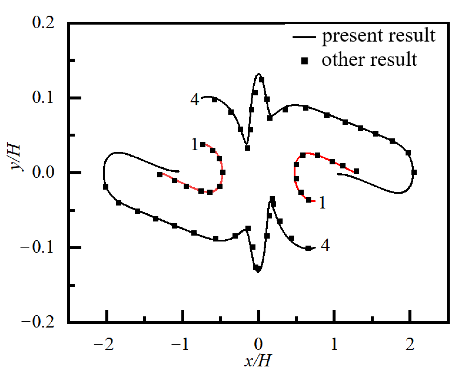
The motion trajectory of a pair of particles with an initial distribution on either side of the centerline in a simple shear flow of a Newtonian fluid without obstacles is shown in Figure 2, where the numbers 1 and 4 represent the two initial positions of the particle pair. The present result is in good agreement with the result given by Yan et al. [41].

3.3. Grid Resolution and Compute-Domain Independence

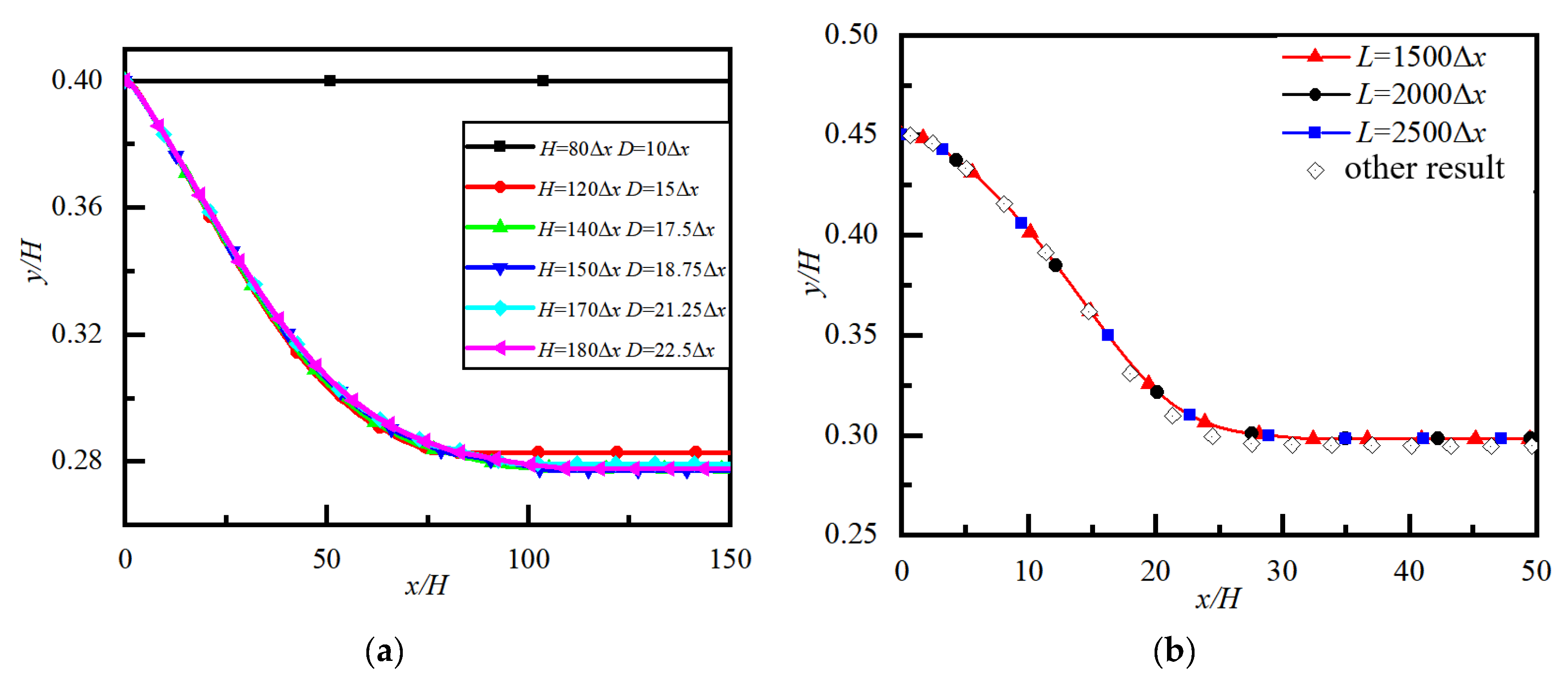
In order to validate that the numerical results do not depend on the number of grids, the numerical results of particle trajectories in channel flow with different channel heights, H, and particle diameters, D, are shown in Figure 3a. For balancing computational efficiency and accuracy, D = 22.5Δx and H = 150∆x are selected in the following numerical simulation.
To verify that the selected channel length L does not affect the numerical results, the numerical results of particle trajectories with different L are shown in Figure 3b, where other numerical results [42] are also given as a comparison. It can be seen that there was only a little difference in the results for three cases, so we selected L = 2000Δx, in the following numerical simulation.

4. Results and Discussion

4.1. Flow and Parameters

Lateral migration and the lateral equilibrium position of particles in a microchannel flow of Newtonian and power-law fluids with an obstacle are studied. As shown in Figure 4, the influence of the upper and lower walls on the flow in the x–y plane with z = 0.5 W can be ignored when H/W ≤ 0.5, so the migration of a neutrally buoyant particle in the x–y plane (cross-section) is considered. A circular obstacle is located on the centerline of the x–y plane, and a particle enters the flow along the x–y plane from the left of the microchannel. The initial streamwise distance between the particle and obstacles is l = 90Δx, and the initial lateral position of the particle is y. Reynolds number is defined as Re = ρU2-nHn/m, where ρ is the fluid density, U is mean velocity, H is channel height, m is the flow consistency coefficient, and n is the power-law index. The blockage ratio is defined as k = D/H.

4.2. Lateral Migration and Equilibrium Position of a Particle without Obstacle

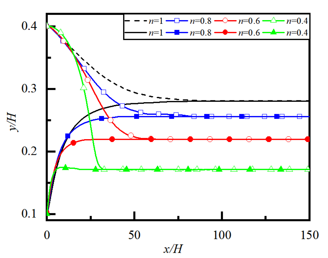
Firstly, the lateral migration and equilibrium position of particles without obstacles are considered. The initial positions of the particles are at y/H = 0.4 and 0.1, respectively. Particle trajectories for different power-law indexs, n, are shown in Figure 5, where we can see that the final equilibrium position of the particle is yeq/H = 0.28 when the particle migrates in Newtonian fluid (n = 1), while the final equilibrium positions of the particle are yeq/H = 0.26, 0.22 and 0.17, respectively, when the particle migrates in shear-thinning fluid with n = 0.8, 0.6 and 0.4. It can be seen that as long as the power law index of the fluid is the same, a particle initially located at different lateral positions will eventually reach the same lateral equilibrium position, which is exactly the so-called SS effect mentioned earlier. The smaller the power law index n of the fluid, the closer the lateral equilibrium position of the particle is to the wall.

4.3. Effect of Obstacle Size on Particle Migration and Lateral Position

4.3.1. Situation near Obstacle

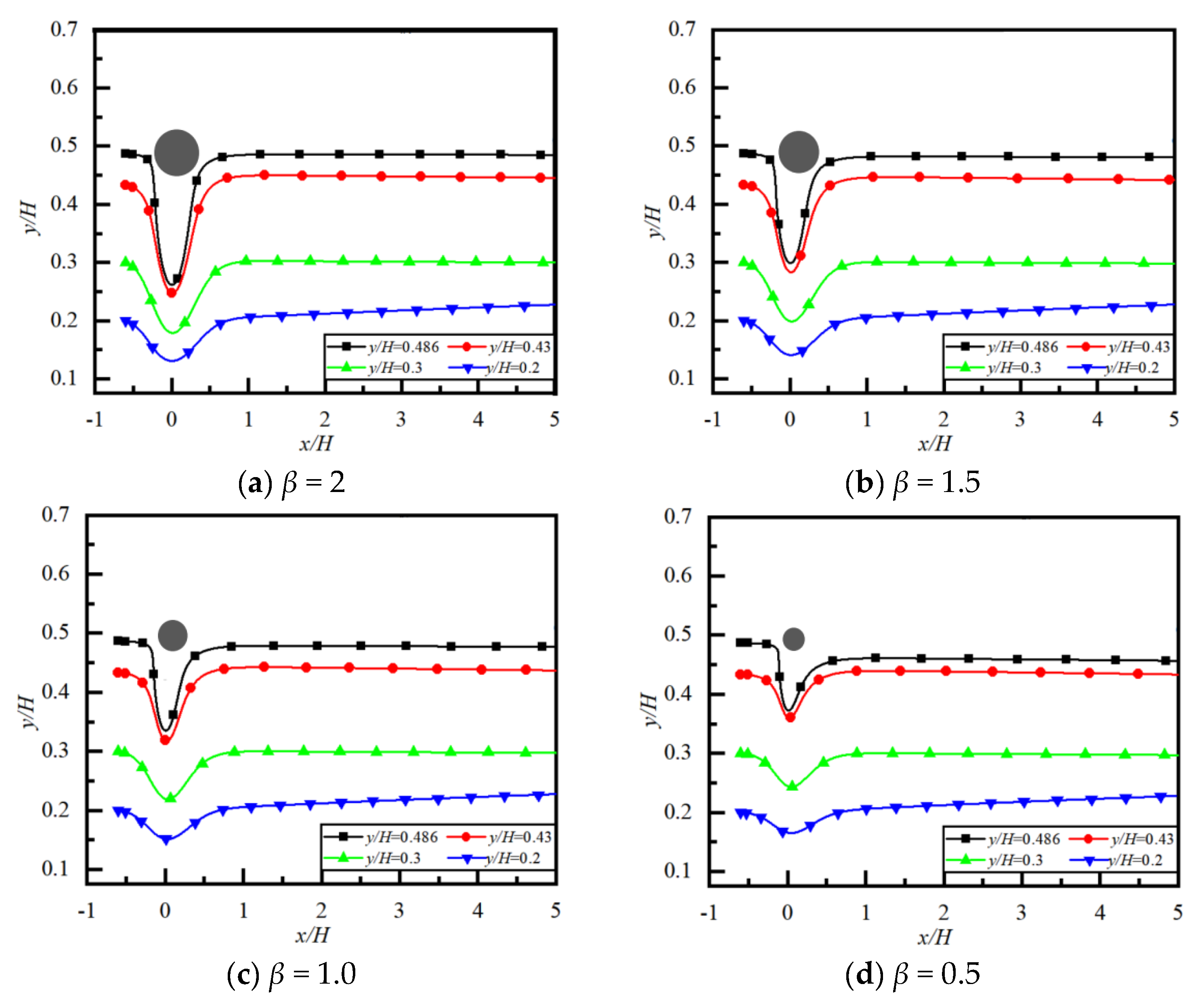
The ratio of obstacle diameter to particle diameter is defined as β = d/D. When there is an obstacle with different β in the flow, how to change the particle trajectory after flowing around the obstacle is the topic to be discussed in this section. The particle trajectories for different β and initial lateral positions y/H (at x/H ≤ 5, i.e., situation near obstacle) are shown in Figure 6, and particle lateral positions at x/H = 5 for different β and y/H are listed in Table 1. It can be seen that (1) When a particle with a different initial y/H migrates around an obstacle, it first moves toward the wall, then toward the centerline, and finally downstream in a different lateral position. (2) A particle with a different initial y/H has different lateral positions at x/H ≤ 5 after migrating around the obstacle, which is different from the situation when there is no obstacle, as shown in Figure 5, where the final lateral equilibrium position yep/H = 0.28 regardless of the initial y/H. (3) The particle lateral positions after migrating around the obstacle are very close to those of the initial y/H. (4) In Table 1, the larger the value of β (i.e., the larger the obstacle size), the closer the particle’s lateral position is to the centerline. Based on the above results, the lateral position of particles can be controlled by changing the obstacle size in the wake zone of the obstacle.

4.3.2. Situations Far Downstream of Obstacle

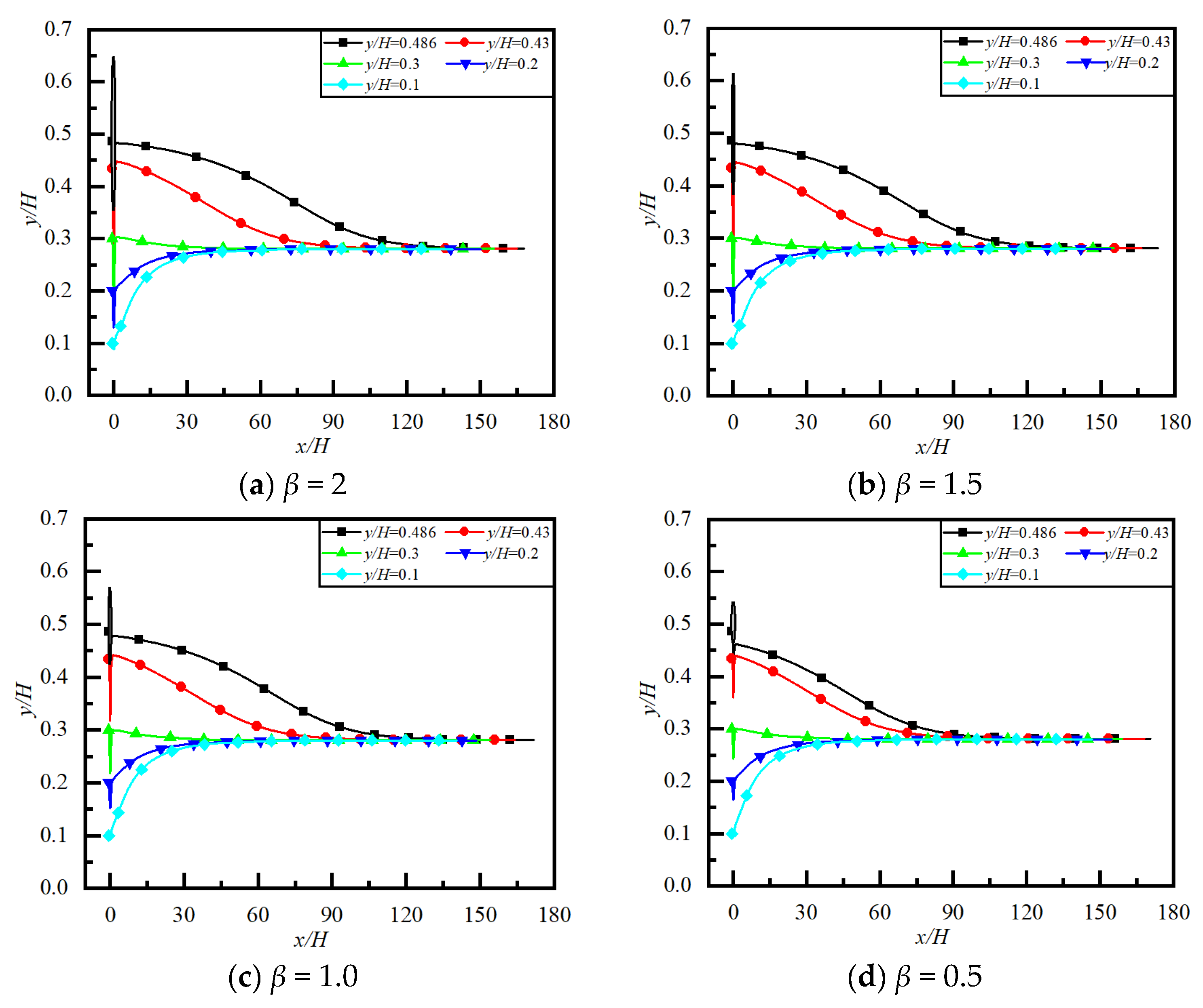
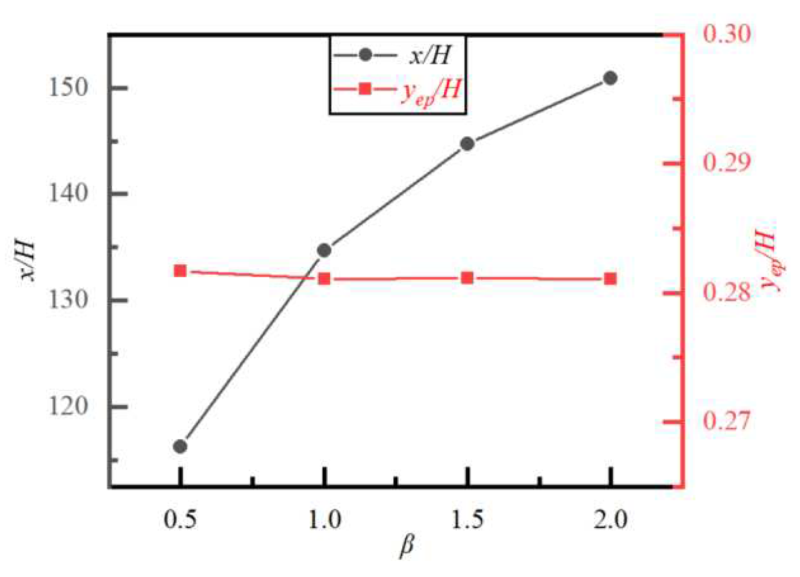
Figure 7 shows the particle trajectories for different β and y/H at 0 ≤ x/H ≤ 180 (situations far downstream of the obstacle). It can be seen that, far downstream from the obstacle, the particle initially located at different y/H tends to the same lateral equilibrium position. This is because the influence of the obstacle on the flow has disappeared far downstream from the obstacle, and the lateral equilibrium position of the particle is the same as when there is no obstacle. Figure 8 shows the equilibrium positions of particles initially located at different y/H and the flow distance required for particles to reach the equilibrium position for different β. We can see that, for the same n, Re and k, the equilibrium positions of particles are almost the same for different β, indicating that the obstacle size has no effect on the equilibrium position of particles far downstream. However, the flow distance required for the particle initially located at a different y/H to reach the same lateral equilibrium position is different when β is different. The larger the value of β (i.e., the larger the obstacle size), the longer the flow distance required for the particle to reach the equilibrium position. The reason is that the larger the value of β, the greater the impact of the obstacle on particle migration and trajectory.

4.4. Effect of Power-Law Index n on Particle Migration and Lateral Equilibrium Position

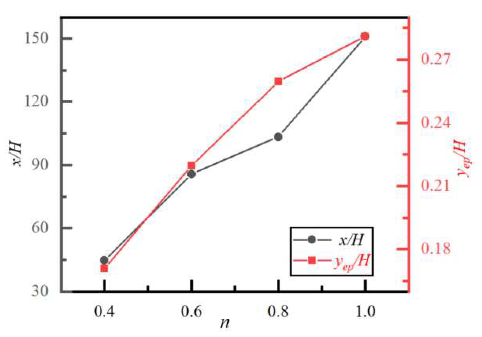
Particle trajectory and lateral equilibrium position yep/H for different n and y/H are shown in Figure 9, where we can see that particles with different initial y/H reach the same yep/H after migrating around obstacles. However, for different n, the values of yep/H are different, and the flow distances required for particles to reach yep/H are also different. Figure 10 displays the yep/H of particles with different initial y/H and the required flow distance to reach yep/H for different n. It can be seen that the larger the value of n (i.e., the weaker the shear-thinning effect), the closer yep/H is to the centerline, which is the same conclusion as in Figure 5 and is consistent with the conclusion of Jeffri and Zahed [43] that the enhancement of the fluid shear-thinning effect will cause yep/H to move toward the wall. On the other hand, the flow distance required for particles to reach yep/H increases with increasing n. The reason may be attributed to the fact that the larger n, the weaker the shear-thinning effect of the fluid, the greater the viscous resistance of the fluid, and thus the stronger the effect of resisting the particle toward yep/H.

4.5. Effect of Reynolds Number Re on Particle Migration and Lateral Equilibrium Position

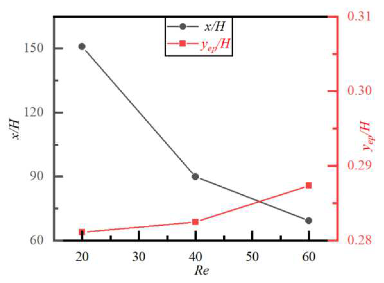
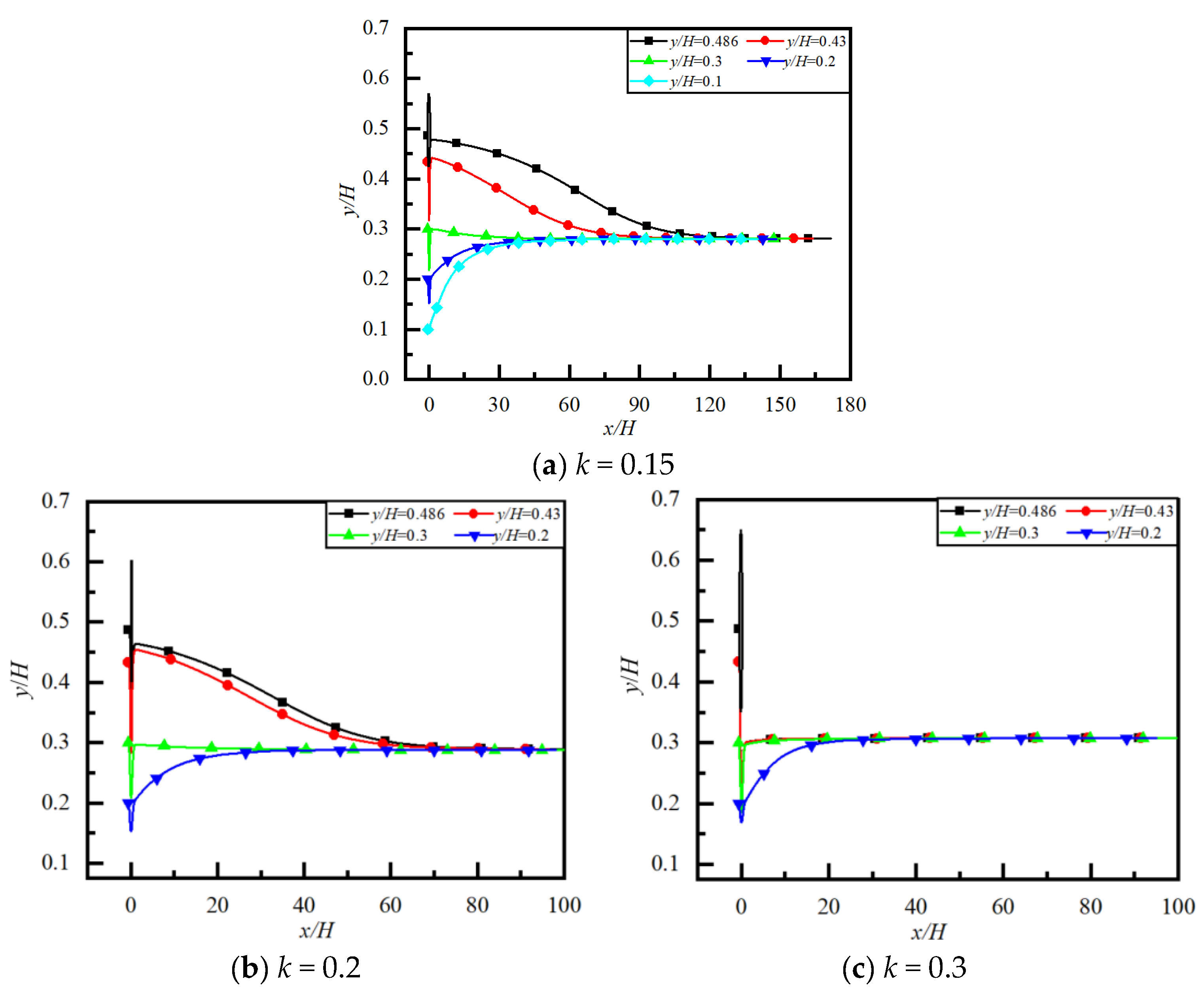
Figure 11 and Figure 12 show the particle trajectory, the lateral equilibrium position yep/H, and the required flow distance to reach yep/H for different Re and y/H. The particle with a different initial y/H finally reaches yep/H after migrating around obstacles for different Re. In the three cases of Re taken in the text, although the difference in yep/H is not significant, the larger the value of Re, the closer yep/H is to the centerline. Nakayama et al. [44] also found that, in the flow of circular tubes at 100 ≤ Re ≤ 1000, yep/H is relatively close to the wall at Re = 100, while it is relatively close to the centerline at Re = 1000. The lateral migration of particles is mainly controlled by inertial forces, which are mainly composed of two parts: the first is the force induced by the parabolic velocity profile that points toward the wall, and the second is the force directed toward the centerline, caused by the symmetry destruction of the wake of particles due to the influence of the wall. When Re is large, the influence of the latter is greater than that of the former, so yep/H is closer to the centerline. In Figure 12, the smaller the value of Re, the longer the flow distance required for particles to reach yep/H. This is because the viscous effect is stronger than the inertial effect under small Re, which has a strong resisting effect on the particle moving toward yep/H.

4.6. Effect of Blockage Ratio k on Particle Migration and Lateral Equilibrium Position

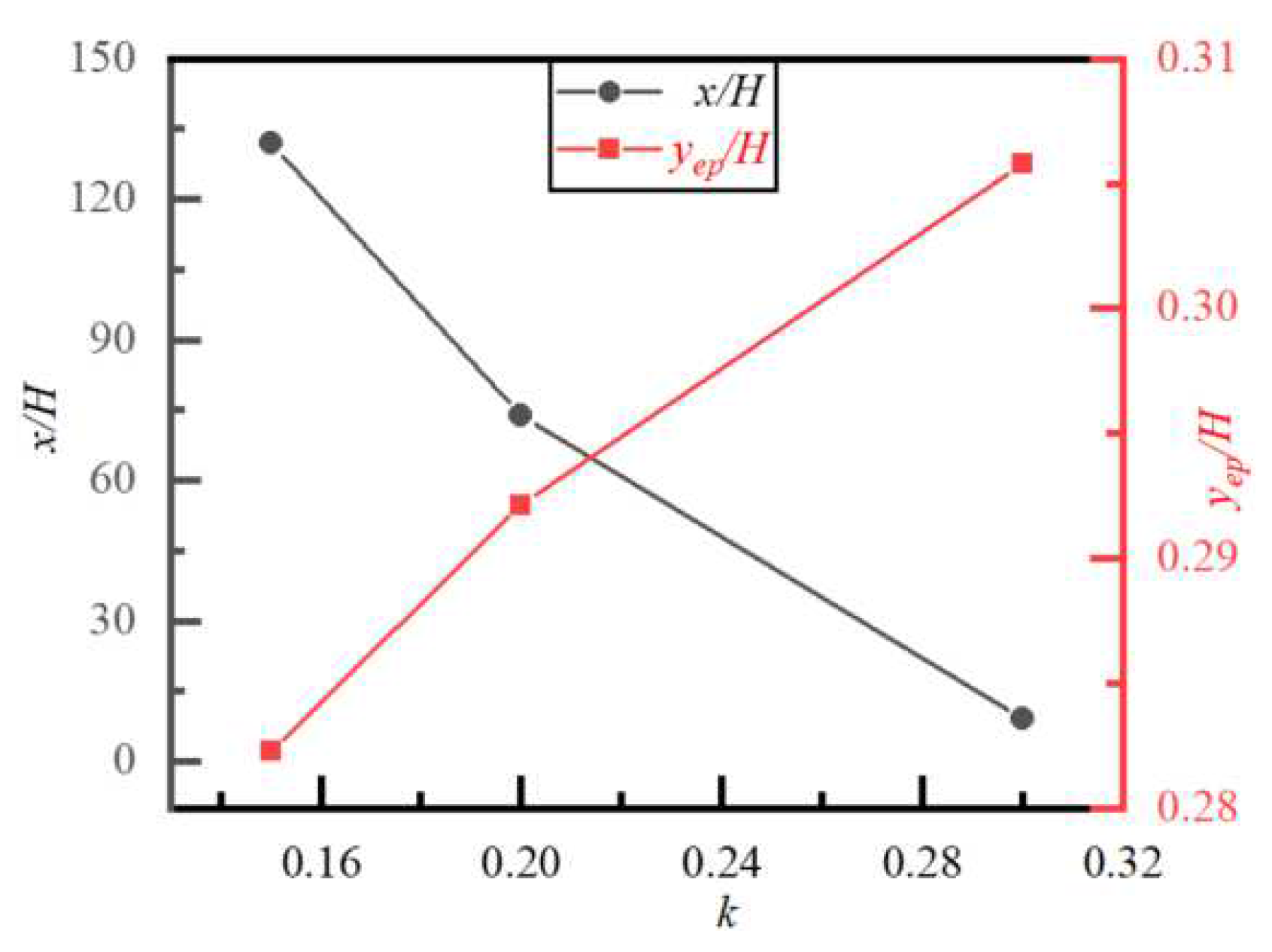
Particle trajectory, lateral equilibrium position, and required flow distance to reach the equilibrium position yep/H for different k and y/H are shown in Figure 13 and Figure 14, respectively. We can see that the particle with a different initial y/H also finally reaches yep/H after migrating around obstacles for different k. The larger the value of k, the closer yep/H is to the centerline. This is because the larger k corresponds to a larger particle (while the channel height H remains constant), and the wall effect has a more significant impact on the symmetry destruction of the wake of a large particle, while the force generated by the symmetry destruction is directed toward the centerline. In Figure 14, the larger the value of k, the shorter the flow distance required for particles to reach yep/H. The reason for this is the same as in the case of Re discussed earlier, i.e., a larger particle (a larger k) means a larger Re while the velocity and viscosity remain constant. At a larger Re, the inertial effect is stronger than the viscous effect, which has a weaker resisting effect on the particles moving toward yep/H. So, the flow distance required for a particle to reach yep/H is shorter in the case of a larger k.

5. Conclusions

Equilibrium position yep/H of particles in a microchannel flow of Newtonian and power-law fluids with an obstacle is numerically studied using the lattice Boltzmann method in the range of 0.5 ≤ β ≤ 2, 0.4 ≤ n ≤ 1, 20 ≤ Re ≤ 60, and 0.15 ≤ k ≤ 0.3. Some results are validated by comparing them with available results. The effects of β, n, Re and k on particle migration and yep/H are discussed. The main conclusions are summarized as follows:
(1) The values of yep/H are 0.28, 0.26, 0.22 and 0.17 when a particle migrates in the fluid with n = 1, 0.8, 0.6 and 0.4, respectively. A particle initially located at different lateral positions y/H will eventually reach the same yep/H as long as n is the same. The smaller the value of n, the closer the value of yep/H is to the wall.
(2) When a particle migrates around an obstacle in the flow behind and near the obstacle, the particle with a different initial y/H migrates downstream in a different lateral position, and the larger the value of β, the closer the particle’s lateral position is to the centerline. Therefore, the value of the lateral position can be controlled by changing β in the wake zone of the obstacle. However, in the flow far downstream from the obstacle, the particle with a different initial y/H tends to have the same yep/H when n, Re and k are fixed, but the values of yep/H are different for different n, Re and k; i.e., the larger the values of n, Re and k, the closer the value of yep/H is to the centerline. The value of β has no effect on the value of yep/H.
(3) In the flow far downstream from the obstacle, the flow distance required for the particle to reach yep/H increases with increasing β and n but decreases with decreasing Re and k.

Author Contributions

Conceptualization, J.L. and D.C.; methodology, D.C. and J.L.; software, D.C.; validation, D.C.; writing, D.C. and J.L.; resources, D.C. and J.L.; review, J.L. All authors have read and agreed to the published version of the manuscript.

Funding

This work was supported by the National Natural Science Foundation of China (Grant No. 12132015).

Institutional Review Board Statement

Not applicable.

Informed Consent Statement

Not applicable.

Data Availability Statement

No applicable.

Conflicts of Interest

There are no conflict of interest regarding the publication of this paper.

References

  1. Di Carlo, D. Inertial microfluidics. Lab A Chip 2009, 9, 3038–3046. [Google Scholar] [CrossRef]
  2. Duffy, D.C.; McDonald, J.C.; Schueller, O.J.A.; Whitesides, G.M. Rapid prototyping of microfluidic systems in poly (dimethylsiloxane). Anal. Chem. 1998, 70, 4974–4984. [Google Scholar] [CrossRef] [PubMed]
  3. Martel, J.M.; Toner, M. Inertial focusing in microfluidics. In Annual Review of Biomedical Engineering; Yarmush, M.L., Ed.; Annual Reviews: SAN Mateo, CA, USA, 2014; pp. 371–396. [Google Scholar]
  4. Wang, R.J.; Lin, J.Z.; Li, Z.H. Analysis of electro-osmotic flow characteristics at joint of capillaries with step change in zeta-potential and dimension. Biomed. Microdevices 2005, 7, 131–135. [Google Scholar]
  5. Gossett, D.R.; Weaver, W.M.; Mach, A.J.; Hur, S.C.; Tse, H.T.K.; Lee, W.; Amini, H.; Di Carlo, D. Label-free cell separation and sorting in microfluidic systems. Anal. Bioanal. Chem. 2010, 397, 3249–3267. [Google Scholar] [CrossRef]
  6. Lagus, T.P.; Edd, J.F. High-throughput co-encapsulation of self-ordered cell trains: Cell pair interactions in microdroplets. RSC Adv. 2013, 3, 20512–20522. [Google Scholar] [CrossRef]
  7. Godino, N.; Jorde, F.; Lawlor, D.; Jaeger, M.; Duschl, C. Purification of microalgae from bacterial contamination using a disposable inertia-based microfluidic device. J. Micromechanics Microengineering 2015, 25, 084002. [Google Scholar] [CrossRef]
  8. Horsman, K.M.; Bienvenue, J.M.; Blasier, K.R.; Landers, J.P. Forensic DNA analysis on microfluidic devices: A review. J. Forensic Sci. 2007, 52, 784–799. [Google Scholar] [CrossRef]
  9. Kang, K.; Lee, S.S.; Hyun, K.; Lee, S.J.; Kim, J.M. DNA-based highly tunable particle focuser. Nat. Commun. 2013, 4, 2567. [Google Scholar] [CrossRef]
  10. Yan, S.; Zhang, J.; Yuan, D.; Li, W.H. Hybrid microfluidics combined with active and passive approaches for continuous cell separation. Electrophoresis 2017, 38, 238–249. [Google Scholar] [CrossRef] [PubMed]
  11. Garcia, A.L.; Akhtar, J.; Saenz, L.; Shu, F.J.; Kuravi, S.; Kota, K. Waviness-induced passive particle manipulation of very dilute suspensions in confined microfluidic flows. Microfluid. Nanofluidics 2023, 27, 30. [Google Scholar] [CrossRef]
  12. Segré, G.; Silberberg, A. Radial particle displacements in poiseuille flow of suspensions. Nature 1961, 189, 209–210. [Google Scholar] [CrossRef]
  13. Oliver, D.R. Influence of particle rotation on radial migration in the poiseuille flow of suspensions. Nature 1962, 194, 1269–1271. [Google Scholar] [CrossRef]
  14. Goldsmith, H.L.; Mason, S.G. Axial migration of particles in poiseuille flow. Nature 1961, 190, 1095–1096. [Google Scholar] [CrossRef]
  15. Ho, B.P.; Leal, L.G. Inertial migration of rigid spheres in two-dimensional unidirectional flows. J. Fluid Mech. 1974, 65, 365–400. [Google Scholar] [CrossRef]
  16. Feng, J.; Hu, H.H.; Joseph, D.D. Direct simulation of initial value problems for the motion of solid bodies in a Newtonian fluid. Part 2. Couette and Poiseuille flows. J. Fluid Mech. 1994, 277, 271–301. [Google Scholar] [CrossRef]
  17. Fox, A.J.; Schneider, J.W.; Khair, A.S. Inertial bifurcation of the equilibrium position of a neutrally-buoyant circular cylinder in shear flow between parallel walls. Phys. Rev. Res. 2020, 2, 013009. [Google Scholar] [CrossRef]
  18. Fox, A.J.; Schneider, J.W.; Khair, A.S. Dynamics of a sphere in inertial shear flow between parallel walls. J. Fluid Mech. 2021, 915, A119-1-23. [Google Scholar] [CrossRef]
  19. Wen, B.; Li, H.B.; Zhang, C.Y.; Fang, H.P. Lattice-type-dependent momentum-exchange method for moving boundaries. Phys. Rev. E Stat. Nonlin. Soft. Matter Phys. 2012, 85, 016704. [Google Scholar] [CrossRef] [PubMed]
  20. Choi, Y.S.; Seo, K.W.; Lee, S.J. Lateral and cross-lateral focusing of spherical particles in a square microchannel. Lab A Chip 2011, 11, 460–465. [Google Scholar] [CrossRef]
  21. D’Avino, G.; Maffettone, P.L. Particle dynamics in viscoelastic liquids. J. Non-Newton. Fluid Mech. 2015, 215, 80–104. [Google Scholar] [CrossRef]
  22. Yu, Z.S.; Wang, P.; Lin, J.Z.; Hu, H.H. Equilibrium positions of the elasto-inertial particle migration in rectangular channel flow of Oldroyd-B viscoelastic fluids. J. Fluid Mech. 2019, 868, 316–340. [Google Scholar] [CrossRef]
  23. Yang, S.; Kim, J.Y.; Lee, S.J.; Lee, S.S.; Kim, J.M. Sheathless elasto-inertial particle focusing and continuous separation in a straight rectangular microchannel. Lab Chip 2011, 11, 266–273. [Google Scholar] [CrossRef] [PubMed]
  24. Chrit, F.E.; Bowie, S.; Alexeev, A. Inertial migration of spherical particles in channel flow of power law fluids. Phys. Fluids 2020, 32, 083103. [Google Scholar] [CrossRef]
  25. Hu, X.; Lin, J.Z.; Ku, X.K. Inertial migration of circular particles in Poiseuille flow of a power-law fluid. Phys. Fluids 2019, 31, 073306. [Google Scholar] [CrossRef]
  26. Tong, S.H.; Han, X.F.; Zhou, F.K.; Xu, X.F. Study on particle aggregation behavior in shear-thinning fluid. Chin. J. Process Eng. 2022, 22, 792–801. [Google Scholar]
  27. Ghomsheh, M.J.; Jafari, A.; Funfschilling, D. Inertial lift on a particle in a straight microchannel of Newtonian, power-law and Carreau-Yasuda fluids: A simulation study toward optimized particle separation. J. Non-Newton. Fluid Mech. 2023, 312, 104977. [Google Scholar] [CrossRef]
  28. Li, B.T.; Chen, X.; Zheng, L.C.; Zhu, L.L.; Zhou, J.L.; Wang, T.T. Precipitation phenomenon of nanoparticles in power-law fluids over a rotating disk. Microfluid. Nanofluidics 2014, 17, 107–114. [Google Scholar] [CrossRef]
  29. Guo, Z.; Shi, B.; Wang, N. Lattice BGK model for incompressible Navier–Stokes equation. J. Comput. Phys. 2000, 165, 288–306. [Google Scholar] [CrossRef]
  30. Nie, D.M.; Lin, J.Z. A LB-DF/FD method for Particle Suspensions. Commun. Comput. Phys. 2010, 7, 544–563. [Google Scholar]
  31. Qian, Y.H.; Dhumieres, D.; Lallemand, P. Lattice BGK models for Navier-Stokes equation. Europhys. Lett. 1992, 17, 479–484. [Google Scholar] [CrossRef]
  32. He, X.Y.; Shan, X.W.; Doolen, G.D. Discrete Boltzmann equation model for nonideal gases. Phys. Rev. E 1998, 57, R13–R16. [Google Scholar] [CrossRef]
  33. Chen, S.; Doolen, G.D. Lattice Boltzmann method for fluid flows. Annu. Rev. Fluid Mech. 1998, 30, 329–364. [Google Scholar] [CrossRef]
  34. Ladd, A.J.C. Numerical simulations of particulate suspensions via a discretized Boltzmann equation. Part 1. Theoretical foundation. J. Fluid Mech. 1994, 271, 285–309. [Google Scholar] [CrossRef]
  35. Ladd, A.J.C. Numerical simulations of particulate suspensions via a discretized Boltzmann equation. Part 2. Numerical results. J. Fluid Mech. 1994, 271, 311–339. [Google Scholar] [CrossRef]
  36. Aidun, C.K.; Lu, Y.; Ding, E.J. Direct analysis of particulate suspensions with inertia using the discrete Boltzmann equation. J. Fluid Mech. 1998, 373, 287–311. [Google Scholar] [CrossRef]
  37. Glowinski, R.; Pan, T.W.; Hesla, T.I.; Joseph, D.D.; Periaux, J. A Fictitious domain approach to the direct numerical simulation of incompressible viscous flow past moving rigid bodies: Application to particulate flow. J. Comput. Phys. 2001, 169, 363–426. [Google Scholar] [CrossRef]
  38. Zhu, Q.Y.; Zhuang, Y.J.; Yu, H.Z. Three-dimensional numerical investigation on thermosolutal convection of power-law fluids in anisotropic porous media. Int. J. Heat Mass Transf. 2017, 104, 897–917. [Google Scholar] [CrossRef]
  39. Drazer, G.; Koplik, J.; Gabbanelli, S. Lattice Boltzmann method for non-Newtonian (power-law) fluids. Phys. Rev. E 2005, 72, 046312. [Google Scholar]
  40. Bird, R.B.; Dai, C.C.; Yarusso, B.J. The rheology and flow of viscoplastic materials. Rev. Chem. Eng. 1983, 1, 1–70. [Google Scholar] [CrossRef]
  41. Yan, Y.; Morris, J.F.; Koplik, J. Hydrodynamic interaction of two particles in confined linear shear flow at finite Reynolds number. Phys. Fluids 2007, 19, 113305. [Google Scholar] [CrossRef]
  42. Hu, X.; Lin, J.Z.; Guo, Y.; Ku, X.K. Motion and equilibrium position of elliptical and rectangular particles in a channel flow of a power-law fluid. Powder Technol. 2021, 377, 585–596. [Google Scholar] [CrossRef]
  43. Jefri, M.A.; Zahed, A.H. Elastic and viscous effects on particle migration in plane-Poiseuille flow. J. Rheol. 1989, 33, 691–708. [Google Scholar] [CrossRef]
  44. Nakayama, S.; Yamashita, H.; Yabu, T.; Itano, T.; Sugihara-Seki, M. Three regimes of inertial focusing for spherical particles suspended in circular tube flows. J. Fluid Mech. 2019, 871, 952–969. [Google Scholar] [CrossRef]
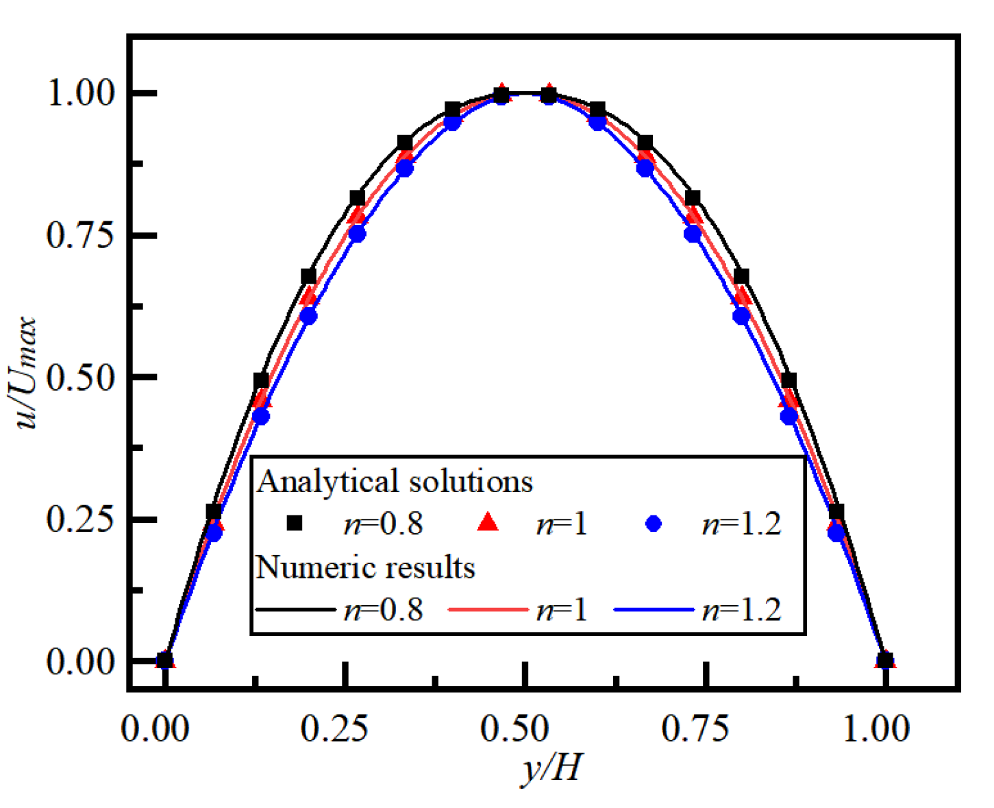
Figure 1. Velocity distributions in the Poiseuille flow of power-law fluid with different indices.
Mathematics 11 03700 g001
Figure 2. Trajectory of a pair of particles with an initial distribution on either side of the centerline in a simple shear flow of a Newtonian fluid. ■: other result [41].
Mathematics 11 03700 g002
Figure 3. Particle trajectories in channel flow with different (a) H and D and (b) L. ◊: other result [42].
Mathematics 11 03700 g003
Figure 4. Particle in a microchannel flow.
Mathematics 11 03700 g004
Figure 5. Particle trajectories for different power-law indexes, n (Re = 20, k = 0.15).
Mathematics 11 03700 g005
Figure 6. Particle trajectories at x/H ≤ 5 for different β and y/H (n = 1, Re = 20, k = 0.15).
Mathematics 11 03700 g006
Figure 7. Particle trajectories at 0 ≤ x/H ≤ 180 for different β and y/H (n = 1, Re = 20, k = 0.15).
Mathematics 11 03700 g007
Figure 8. Equilibrium position of particles and the flow distance required for particles to reach the equilibrium position for different β (n = 1, Re = 20, k = 0.15).
Mathematics 11 03700 g008
Figure 9. Particle trajectory and lateral equilibrium position for different n and y/H (β = 1, Re = 20, k = 0.15).
Mathematics 11 03700 g009
Figure 10. Equilibrium position of a particle and the required flow distance to reach the equilibrium position for different n (β = 2, Re = 20, k = 0.15).
Mathematics 11 03700 g010
Figure 11. Particle trajectory and lateral equilibrium position for different Re and y/H (β = 1, n = 1, k = 0.15).
Mathematics 11 03700 g011
Figure 12. Equilibrium position of a particle and the required flow distance to reach the equilibrium position for different Re (β = 1, n = 1, k = 0.15).
Mathematics 11 03700 g012
Figure 13. Particle trajectory and lateral equilibrium position for different k and y/H (β = 1, n = 1, Re = 20).
Mathematics 11 03700 g013
Figure 14. Equilibrium position of a particle and the required flow distance to reach the equilibrium position for different k (β = 1, n = 1, Re = 20).
Mathematics 11 03700 g014
Table 1. Particle lateral positions at x/H = 5 for different β and y/H.
y/H = 0.2y/H = 0.3y/H = 0.43y/H = 0.486
β = 20.230.30.4480.485
1.50.230.2980.4430.481
1.00.2280.2980.4390.477
0.50.2250.2970.4350.457
Disclaimer/Publisher’s Note: The statements, opinions and data contained in all publications are solely those of the individual author(s) and contributor(s) and not of MDPI and/or the editor(s). MDPI and/or the editor(s) disclaim responsibility for any injury to people or property resulting from any ideas, methods, instructions or products referred to in the content.