Article

Projectile Motion in Special Theory of Relativity: Re-Investigation and New Dynamical Properties in Vacuum

by
Ebrahem A. Algehyne
1,*,
Abdelhalim Ebaid
1,*,
Essam R. El-Zahar
2,3,
Musaad S. Aldhabani
1,
Mounirah Areshi
1 and
Hind K. Al-Jeaid
4
1
Department of Mathematics, Faculty of Science, University of Tabuk, P.O. Box 741, Tabuk 71491, Saudi Arabia
2
Department of Mathematics, College of Science and Humanities in Al-Kharj, Prince Sattam bin Abdulaziz University, P.O. Box 83, Al-Kharj 11942, Saudi Arabia
3
Department of Basic Engineering Science, Faculty of Engineering, Menoufia University, Shebin El-Kom 32511, Egypt
4
Department of Mathematical Sciences, Faculty of Applied Sciences, Umm Al-Qura University, Makkah 21955, Saudi Arabia
*
Authors to whom correspondence should be addressed.
Mathematics 2023, 11(18), 3890; https://doi.org/10.3390/math11183890
Submission received: 20 July 2023 / Revised: 24 August 2023 / Accepted: 30 August 2023 / Published: 13 September 2023

Abstract

:
The projectile motion (PP) in a vacuum is re-examined in this paper, taking into account the relativistic mass in special relativity (SR). In the literature, the mass of the projectile was considered as a constant during motion. However, the mass of a projectile varies with velocity according to Einstein’s famous equation m = m 0 1 v 2 / c 2 , where m 0 is the rest mass of the projectile and c is the speed of light. The governing system consists of two-coupled nonlinear ordinary differential equations (NODEs) with prescribed initial conditions. An analytical approach is suggested to treat the current model. Explicit formulas are determined for the main characteristics of the relativistic projectile (RP) such as time of flight, time of maximum height, range, maximum height, and the trajectory. The relativistic results reduce to the corresponding ones of the non-relativistic projectile (NRP) in Newtonian mechanics, when the initial velocity is not comparable to c. It is revealed that the mass of the RP varies during the motion and an analytic formula for the instantaneous mass in terms of time is derived. Also, it is declared that the angle of maximum range of the RP depends on the launching velocity, i.e., unlike the NRP in which the angle of maximum range is always π / 4 . In addition, this angle lies in a certain interval [ π / 4 , π / 6 ) for any given initial velocity (<c). The obtained results are discussed and interpreted. Comparisons with a similar problem in the literature are performed and the differences in results are explained.

1. Introduction

In the literature, the projectile problem (PP) has been extensively discussed in text books [1,2]. Further, it was investigated in Newtonian mechanics using classical calculus [3,4,5,6,7,8] and also in view of fractional calculus [9,10,11,12,13]. However, the above studies considered the PP when the initial velocity of the projectile is small when compared to the speed of light c. In such studies, the initial (rest) mass m 0 of the projectile remains constant during the motion. However, the situation is different when the velocity of the projectile becomes a considerable value compared to c, such as 0.5 c or 0.9 c . In this case, the relativistic mass m should be taken into account according to the SR. This means that m is not constant after launching the projectile and so, the non-relativistic mechanics (Newtonian mechanics) is no longer valid to treat the PP with velocities comparable to c. Also, the Earth’s gravitational force acting on the projectile changes due to the change in mass. These points were not addressed in Refs. [14,15], in which the Earth’s gravitational force was taken as a constant during the motion. The discussion above motivated us to reconsider the PP, taking into account the Lorentz relativistic factor 1 1 v 2 / c 2 . The equations of motion will be formulated for the relativistic projectile (RP) utilizing the Newtonian second law of motion in relativistic form. It may be important here to point out that the authors in Refs. [14,15,16] formulated the equations of motion of the RP and pendula utilizing the relativistic form of the Newtonian second law of motion.
In addition, the authors [14,15,16] confirmed that it is not obligatory to use the covariant equations [17] (page 94) to study all physical issues in special relativity, especially when studying the projectile and the pendulum. In the present work, we follow the analysis [14,15] to re-investigate the RP problem by considering another point of view regarding the influence of Earth’s gravitational field on the mass of the RP. By this, the equations of motion of the RP are constructed in more complex forms than those in Refs. [14,15]. Accordingly, the features of the RP in our study are completely different than those previously found in the relevant literature. This work may have applications in several areas and problems of physics [18,19,20,21,22,23,24]. The current calculation may be useful when studying the time dilation of a relativistic particle through curved trajectories [18] in addition to the bullet problem, which treats the case when a faster bullet collides with a slower preceding one, and they mutually annihilate [19]. Furthermore, the occurrence of ballistic annihilation was also recently studied by Junge et al. [20]. The radio friction [21] and the ‘optical bullets’ appearing in laser technology [22] might also be useful as additional applications. Moreover, a promising application to build tiny accelerators is the so-called Laser Wakefield acceleration (LWFA) scheme; electrons are accelerated in a plasma wave trailing the laser pulse during the propagation through an ionized gas. The associated accelerating field is on the order of 100 GV/m and thus three to four orders of magnitude higher compared to state-of-the-art radio-frequency accelerators; see Ref. [23] for details. The Teravolt bullets discussed by the Alice team [24] of the CERN in Geneva are another application. In this context, other useful works have been also introduced by Carbajo et al. [25,26].
The present model generalizes both of the previous models of the RP [14,15] in addition to the non-relativistic projectile (NRP) discussed in text books [1,2]. The horizontal and vertical velocities for the RP will be analytically obtained. Moreover, the displacements of the RP in the horizontal and vertical directions will be derived in analytic forms. Furthermore, the properties of the RP such as the time of maximum height, the time of flight, the maximum height, the range, maximum angle, and the trajectory will be discussed. A new concept called the minimum mass of the RP is introduced for the first time. Explicit formulas for such properties will be provided. It will be shown that the present results for the RP reduce to the corresponding ones of the NRP for much lower initial velocity when compared to c.

2. Formulation Using Newton’s Second Law in Relativistic Form

Consider the PP a projectile of initial mass m 0 which is constant in the system S ( x o y ) attached to the projectile. Suppose that v is the velocity of the projectile at any instant. Then, v is the relative velocity of the system S with respect to another fixed system S ( x o y ) in which the motion of the projectile is to be observed. While m 0 is constant in the system S , it varies and depends on v for an observer in S. Let m denote the mass in S; then m = m 0 1 v 2 / c 2 , as stated earlier by Einstein. Hence, the observer in S measures the Earth’s gravitational force F acting on the projectile as F = m g (g is the acceleration due to gravity of Earth) or F = m 0 g 1 v 2 / c 2 , which depends on v, i.e., unlike in Ref. [14], in which F was taken as a constant.
Assuming the motion in a vacuum within the Earth’s gravitational field and applying the Newtonian second haw of motion in relativistic form, the basic equation of motion in the x y plane for the RP can be expressed in a vector form:
d d t ( m v ) = m g ,
where the vectors v and g = ( 0 , g ) stand for the instantaneous velocity of the projectile and the acceleration due to gravity of the Earth, respectively. In Ref. [15], the term of the Earth’s gravitational force, on the right-hand side, was taken as m 0 g , i.e., constant during the motion; this assumption is not realistic from our point of view, as explained above. So, the RP is re-modeled by Equation (1), which can be written as
m d v d t + d m d t v = m g .
The derivative d m d t is
d m d t = m 0 v d v d t ( c 2 v 2 ) 3 / 2 = m v d v d t c 2 v 2 ,
and hence Equation (2) reduces to
d v d t + v d v d t c 2 v 2 v = g .
Assume that u ( t ) = d x d t and w ( t ) = d y d t are, respectively, the horizontal and vertical components of the instantaneous velocity v ( t ) , i.e., v ( t ) = u ( t ) i + w ( t ) j ; then Equation (4) splits to the following two-coupled NODEs with initial conditions:
d u d t + v d v d t c 2 v 2 u = 0 , u ( 0 ) = u 0 = v 0 cos θ 0 , x ( 0 ) = 0 ,
d w d t + v d v d t c 2 v 2 w = g , w ( 0 ) = w 0 = v 0 sin θ 0 , y ( 0 ) = 0 ,
where the RP is launched from the origin o with initial velocity v 0 and elevation angle θ 0 . The above model for the RP is completely different than that one in Ref. [15]. Consequently, new results are expected in this paper for the RP. Indeed, the above set of equations can also be derived via applying the covariant equations in the SR; see Appendix A.

3. Solutions and Analysis

In this section, the above two-coupled NODEs are to be solved analytically using fundamental solution methods such as the separation of variable technique. Let us begin with integrating Equation (5) with respect to the time t, utilizing the separation of variables technique; this gives
ln u u 0 1 2 ln c 2 v 2 c 2 v 0 2 = 0 ,
which leads to
u 2 = u 0 2 c 2 v 2 c 2 v 0 2 ,
Substituting the total velocity v = u 2 + w 2 and simplifying, Equation (8) gives the following relation between the velocity components u and w:
u 2 = u 0 2 c 2 w 2 c 2 w 0 2 .
In order to solve the NODE given by Equation (6), we should first obtain v in terms of only w. From Equation (9) and v 2 = u 2 + w 2 , we can write
v 2 = a + b w 2 ,
where a and b are the following two constants:
a = u 0 2 c 2 c 2 w 0 2 , b = c 2 v 0 2 c 2 w 0 2 .
According to Equation (10), we deduce that v d v d t = b w d w d t , and thus Equation (6) becomes
d w d t + b w 2 d w d t c 2 a b w 2 = g ,
which reduces to
c 2 a + ( 1 b ) w 2 c 2 a b w 2 d w = g d t .
Integrating both sides gives
t = 1 g c 2 a b tanh 1 b c 2 a w tanh 1 b c 2 a w 0 b 1 g b × c 2 a b w w 0 + tanh 1 b c 2 a w 0 tanh 1 b c 2 a w .
Implementing the relations (11), we find that
c 2 a = c 4 c 2 v 0 2 c 2 w 0 2 , c 2 a b = c 2 ,
b 1 = u 0 2 c 2 w 0 2 , b 1 b = u 0 2 c 2 v 0 2 .
Substituting (15) and (16) into (14) and simplifying yields
t = u 0 2 ( w w 0 ) g ( c 2 v 0 2 ) + c ( c 2 w 0 2 ) g ( c 2 v 0 2 ) tanh 1 w 0 c tanh 1 w c .
Equation (17) can be further simplified using the following assumptions:
A = u 0 2 g ( c 2 v 0 2 ) , B = w 0 u 0 2 g ( c 2 v 0 2 ) = w 0 A , D = c ( c 2 w 0 2 ) g ( c 2 v 0 2 ) ,
E = B + D tanh 1 w 0 c .
Therefore,
t = A w + E D tanh 1 w c .
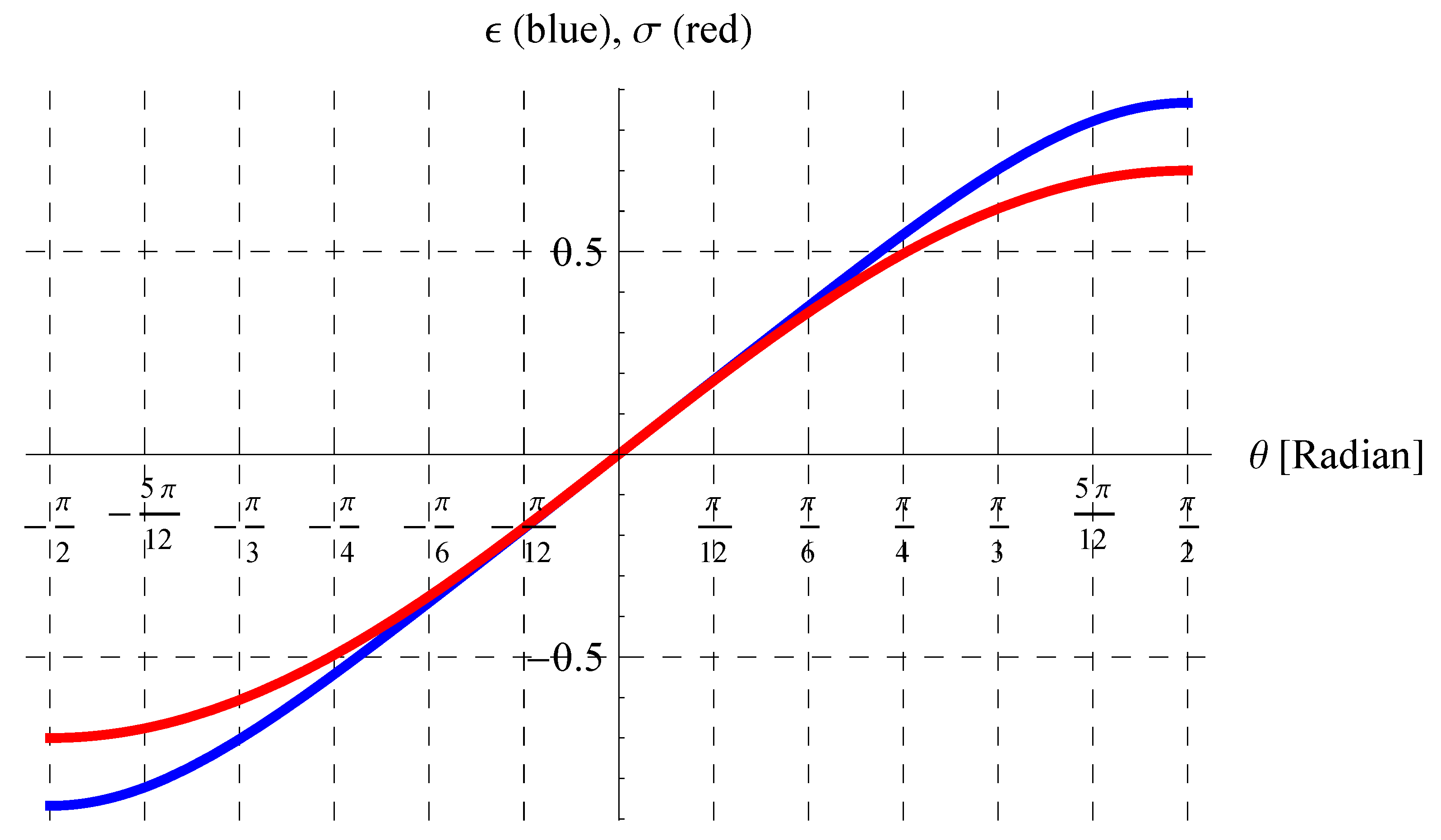
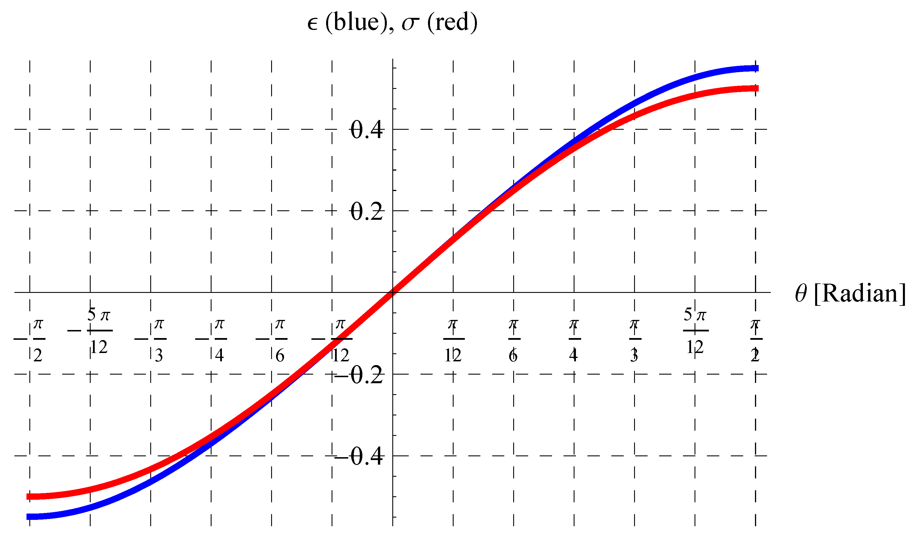
The analytical solution of this equation is not available; hence, an explicit formula for w in terms of t is a challenge. Such a difficulty can be overcome by searching for an accurate analytic approximation of tanh 1 w c in terms of w, as demonstrated below. Let ϵ ( v ) = tanh 1 w c = tanh 1 v sin θ c and σ ( v ) = v sin θ c , where θ is the angle of the instantaneous velocity v with the horizontal axes x at a moment t. Figure 1, Figure 2, Figure 3 and Figure 4 show the curves of ϵ and σ at different values of v in the domain π / 2 θ π / 2 . These figures indicate that the curves of ϵ and σ are nearly identical for θ [ π / 6 , π / 6 ] when v = 0.9 c (Figure 1), θ [ 5 π / 24 , 5 π / 24 ] when v = 0.7 c (Figure 2), θ [ π / 4 , π / 4 ] when v = 0.5 c (Figure 3), and θ [ π / 2 , π / 2 ] (complete domain) when v = 0.2 c (Figure 4). Therefore, the approximation tanh 1 w c w c can be applied, taking into account the above considerations. The validation of such an approach will be extensively addressed in the discussion section. Accordingly, Equation (20) becomes
t = E + A D c w .
The vertical displacement y can be easily obtained by substituting w = d y d t into Equation (21); hence,
t = E + A D c d y d t .
The above approximation is therefore useful for obtaining the analytic integration of the ODE in Equation (22). Thus,
t 2 2 = E t + A D c y ( t ) ,
that is,
y ( t ) = E t + t 2 / 2 A D / c .
From Equation (18), we have the expression A D / c = 1 g and hence,
y ( t ) = E g t 1 2 g t 2 ,
where E is already given by Equation (19). Inserting A D / c = 1 g into Equation (21), we obtain w = g ( E t ) , and hence Equation (9) becomes
u 2 = u 0 2 c 2 g 2 ( t E ) 2 c 2 w 0 2 ,
which yields
u = d x d t = u 0 c 2 w 0 2 c 2 g 2 ( t E ) 2 .
The horizontal displacement x ( t ) can be obtained by solving the following integral:
x ( t ) = u 0 c 2 w 0 2 0 t c 2 g 2 ( τ E ) 2 d τ .
Using the substitution
τ = E + c g sin σ ,
we have
x ( t ) = u 0 c 2 w 0 2 sin 1 ( E g / c ) sin 1 ( ( t E ) g / c ) c 2 g cos 2 σ d σ ,
that is,
x ( t ) = u 0 c 2 2 g c 2 w 0 2 sin 1 ( t E ) g c + sin 1 E g c + ( t E ) g c 1 ( t E ) 2 g 2 c 2 + E g c 1 E 2 g 2 c 2 .
The results of the NRP can be recovered as a special case of the current results for the RP. This issue is addressed in the next section.

4. Special Case: Non-Relativistic Projectile (NRP) v 0 c

For the projectile motion with classical initial velocity v 0 c , i.e., v 0 is not comparable to the speed of light c, the higher terms of v 0 / c , u 0 / c , and w 0 / c can be ignored. In this case, we have from Equations (18) and (19) that
E = w 0 u 0 2 g ( c 2 v 0 2 ) + c ( c 2 w 0 2 ) g ( c 2 v 0 2 ) × w 0 c ,
where the approximation tanh 1 w 0 c w 0 c is used. Simplifying the last equation leads to
E = w 0 g .
Inserting the value of E into Equation (25), we obtain
y ( t ) = w 0 t 1 2 g t 2 ,
or
y ( t ) = ( v 0 sin θ 0 ) t 1 2 g t 2 ,
which is the same vertical displacement for the NRP. Also, Equation (31) becomes
x ( t ) = u 0 c 2 2 g c 2 w 0 2 sin 1 g t w 0 c + sin 1 w 0 c + g t w 0 c 1 ( g t w 0 ) 2 c 2 + w 0 c 1 w 0 2 c 2 .
Applying the approximations sin 1 g t w 0 c g t w 0 c and sin 1 w 0 c w 0 c , we obtain
x ( t ) = u 0 c 2 2 g c 2 w 0 2 g t w 0 c + w 0 c + g t w 0 c + w 0 c , = u 0 c t c 2 w 0 2 , = u 0 t 1 w 0 2 c 2 , = u 0 t = ( v 0 cos θ 0 ) t ,
which is also the corresponding horizontal displacement for the NRP.

5. Properties of the Relativistic Projectile (RP)

Here, we derive the main characteristics of the RP such as the time of maximum height T h , the maximum height h, the time of flight T f , the range R, and the trajectory. Also, it should be noted that the present properties for the RP, discussed in this section, reduce to the corresponding ones of the NRP when v 0 c ; see Appendix B for proofs. The difference between our results and those in Ref. [14] will be addressed in detail in a subsequent section.

5.1. Time of Maximum Height T h

The projectile reaches its maximum height when its vertical velocity w vanishes, i.e., w = 0 . In this case, we have from Equation (21) that
T h = E = w 0 u 0 2 g ( c 2 v 0 2 ) + c ( c 2 w 0 2 ) g ( c 2 v 0 2 ) tanh 1 w 0 c .

5.2. Maximum Height h

The maximum height h is obtained by substituting T = E into Equation (25), and hence
h = 1 2 g E 2 = 1 2 g w 0 u 0 2 c 2 v 0 2 + c ( c 2 w 0 2 ) c 2 v 0 2 tanh 1 w 0 c 2 .

5.3. Time of Flight T f

The time of flight T f can be determined by solving the algebraic Equation (25) at t = T f , i.e., y ( T f ) = 0 ; hence,
T f = 2 E = 2 w 0 u 0 2 g ( c 2 v 0 2 ) + 2 c ( c 2 w 0 2 ) g ( c 2 v 0 2 ) tanh 1 w 0 c ,
where the parameter values in Equations (18) and (19) are employed.

5.4. Range R

The range of a projectile is deduced by substituting the t = T f = 2 E into the horiontal displacement x ( t ) , i.e., R = x ( T f ) = x ( 2 E ) ; thus,
R = u 0 c 2 g c 2 w 0 2 sin 1 E g c + E g c 1 E 2 g 2 c 2 .

5.5. Trajectory

The trajectory of a projectile is simply the relation between x and y in the absence of the time t. From Equation (25), we find
t = E + E 2 2 y g .
On substituting (42) into (31), we obtain
2 g x u 0 c 1 w 0 2 c 2 = sin 1 g 2 E 2 2 g y c + sin 1 E g c + g 2 E 2 2 g y c 1 g 2 E 2 2 g y c 2 + E g c 1 E 2 g 2 c 2 .

5.6. Minimum Mass

Here, we introduce the concept of minimum mass for the first time. Let us denote the minimum mass of the RP by m m . The m m is defined as the minimal value for the mass that may occur during the motion. Before deriving such a value m m , we have to obtain a general formula for m in terms of v or t. The derivative d m d t is already given by Equation (3), which can be easily integrated with respect to time t to give
m ( t ) = m 0 1 v 0 2 c 2 1 v 2 ( t ) c 2 ,
or
m ( t ) = γ ( t ) m 0 , γ ( t ) = 1 v 0 2 c 2 1 v 2 ( t ) c 2 .
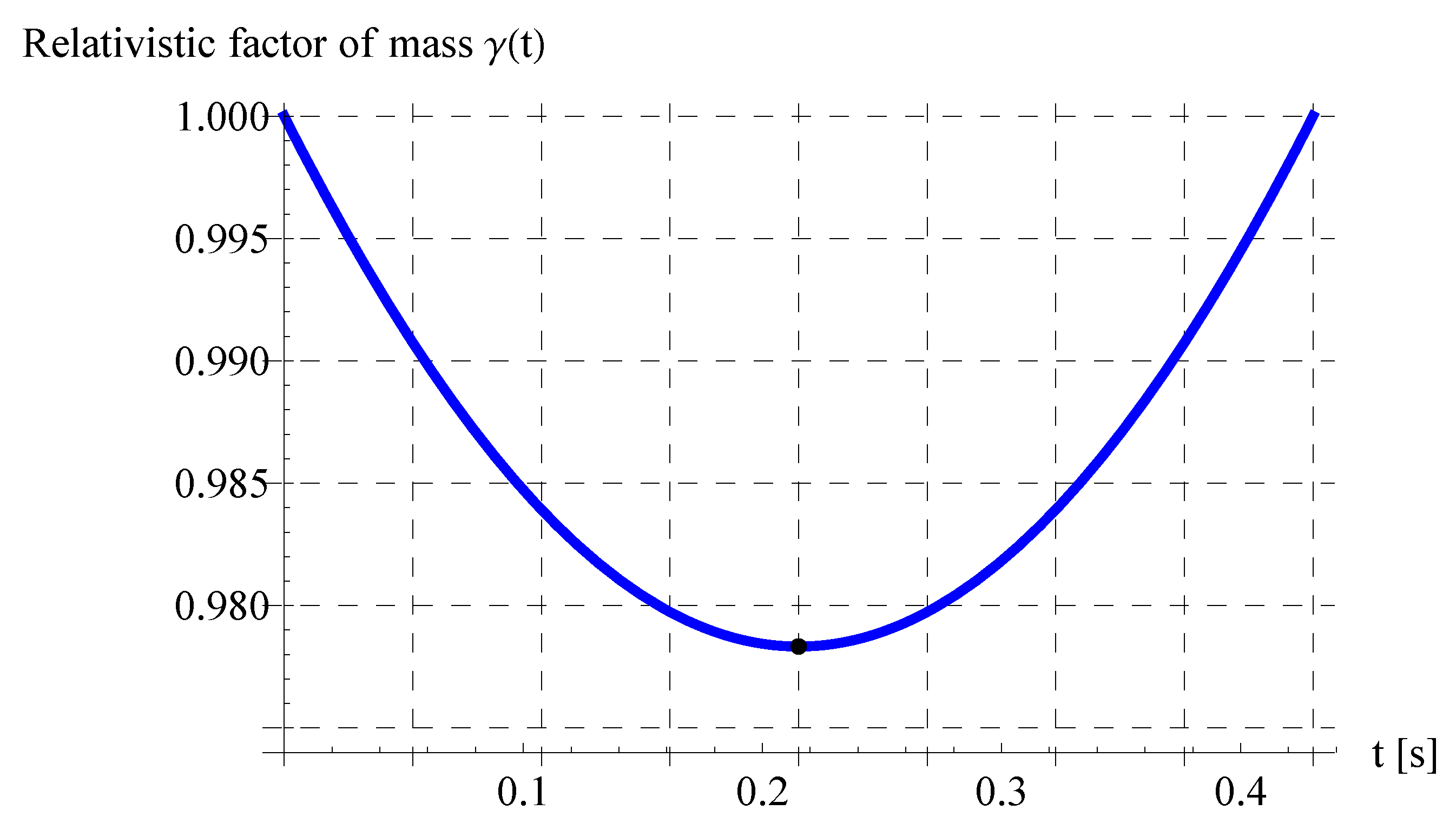
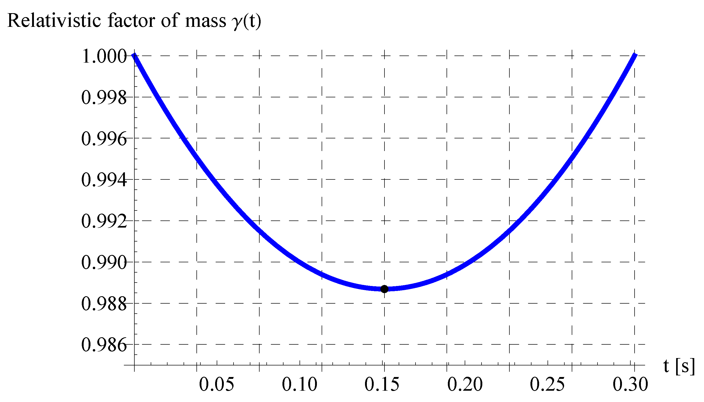
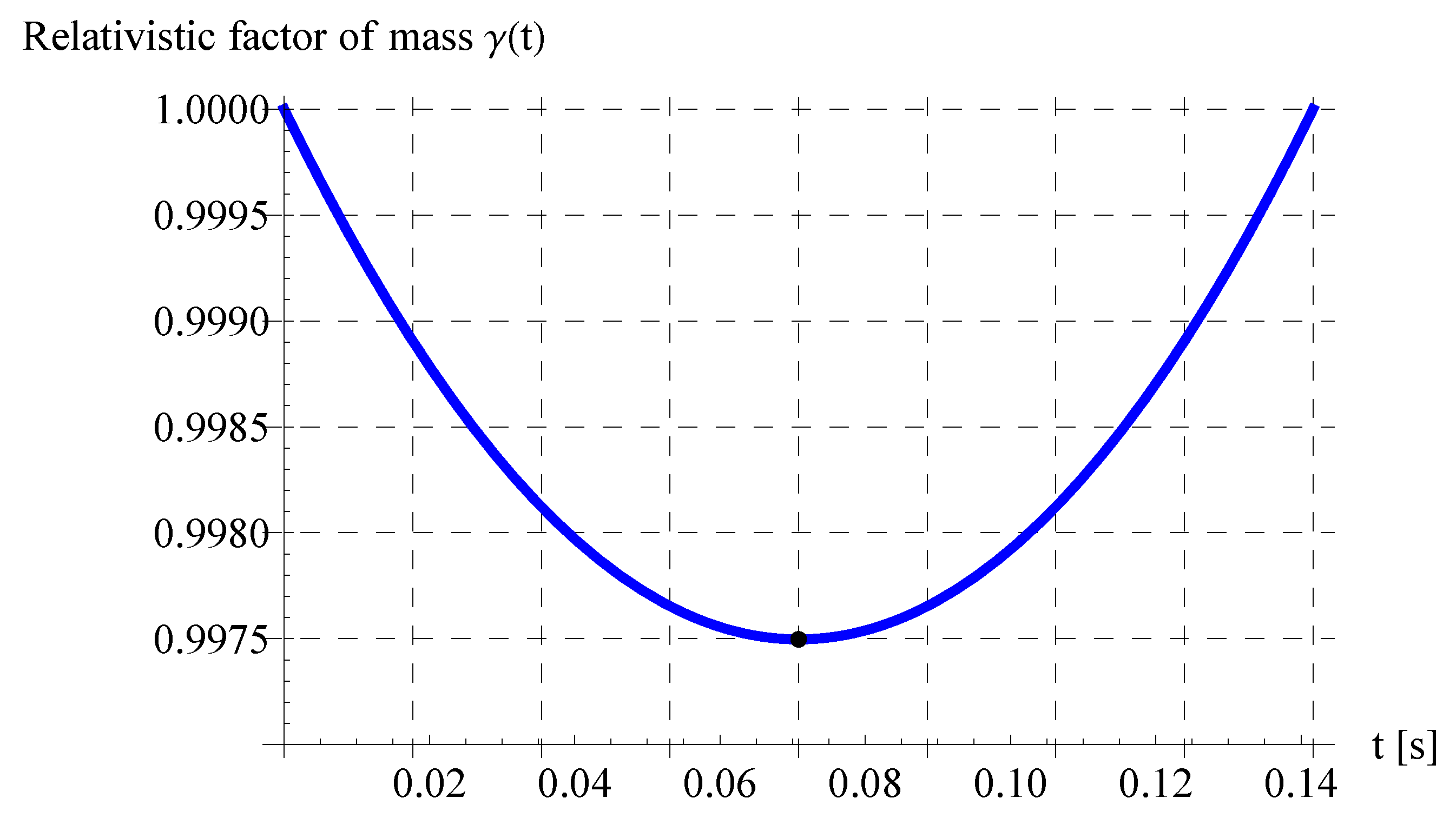
Since v 2 ( t ) < v 0 2 ( t ) t > 0 , then γ ( t ) < 1 t > 0 while γ ( 0 ) = 1 at t = 0 . By this, we have m ( 0 ) = m 0 at the initial time t = 0 and m ( t ) < m 0 t > 0 , i.e., the mass of the RP decreases with the progress of time. According to Equation (45), m ( t ) is minimum when γ ( t ) is minimum too. It is clear from Equation (45) that γ ( t ) is minimum when v 2 ( t ) is also minimum. This happens at the time of maximum height, i.e., t = E in which the vertical velocity w ( t ) vanishes, and hence the total velocity equals the horizontal velocity component at that moment, i.e., v 2 ( E ) = u 2 ( E ) . Therefore, the minimum mass m m is given from Equation (45) by
m m = γ ( E ) m 0 , γ ( E ) = 1 v 0 2 c 2 1 u 2 ( E ) c 2 .
On using Equation (9) at t = E , we obtain
u 2 ( E ) = u 0 2 c 2 c 2 w 0 2 .
Inserting (47) into (46), we obtain
m m = m 0 1 w 0 2 c 2 , γ ( E ) = 1 w 0 2 c 2 .
In terms of v 0 and θ 0 , we have
m m = m 0 1 v 0 2 sin 2 θ 0 c 2 , γ ( E ) = 1 v 0 2 sin 2 θ 0 c 2 .

6. Results and Discussion

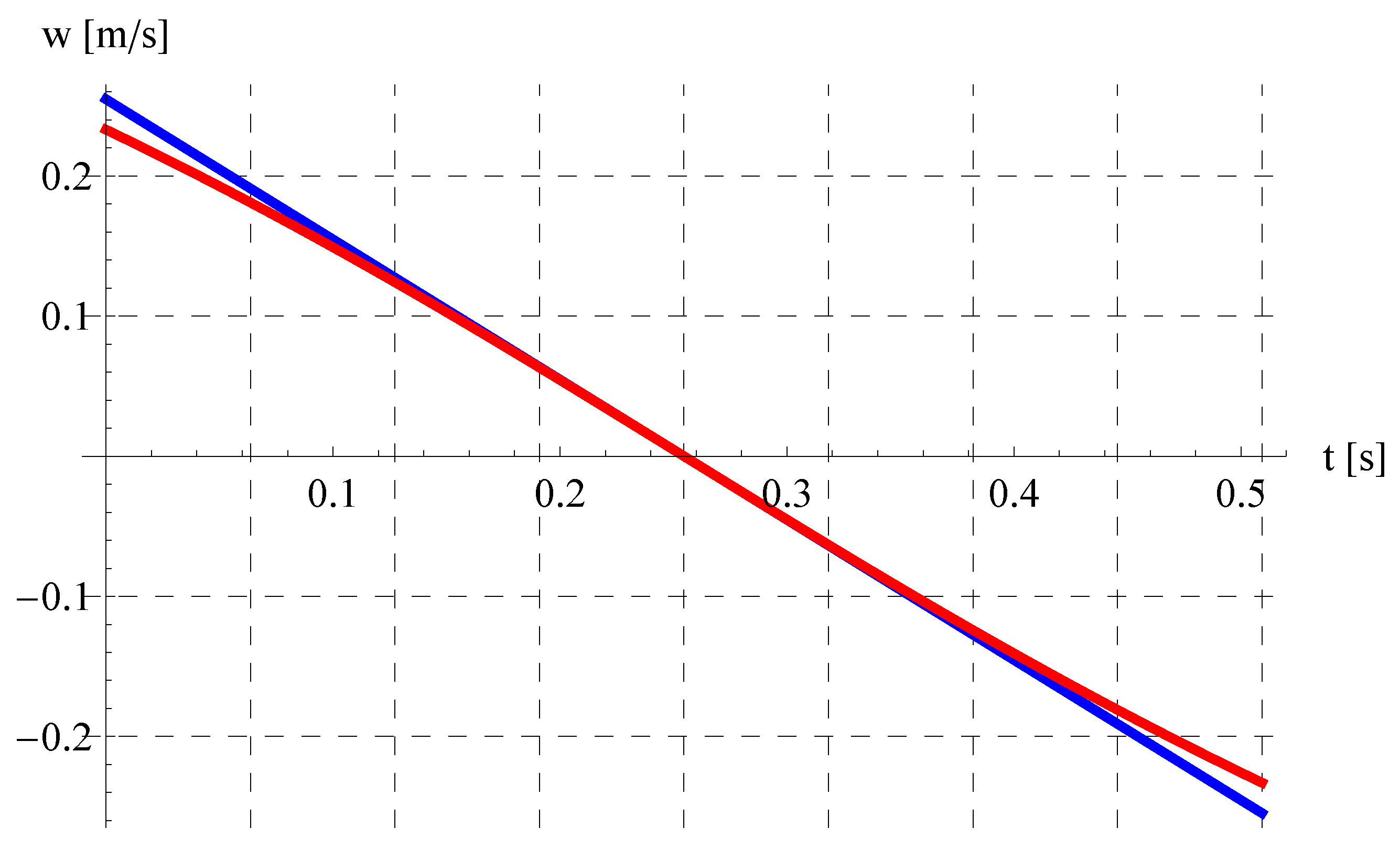
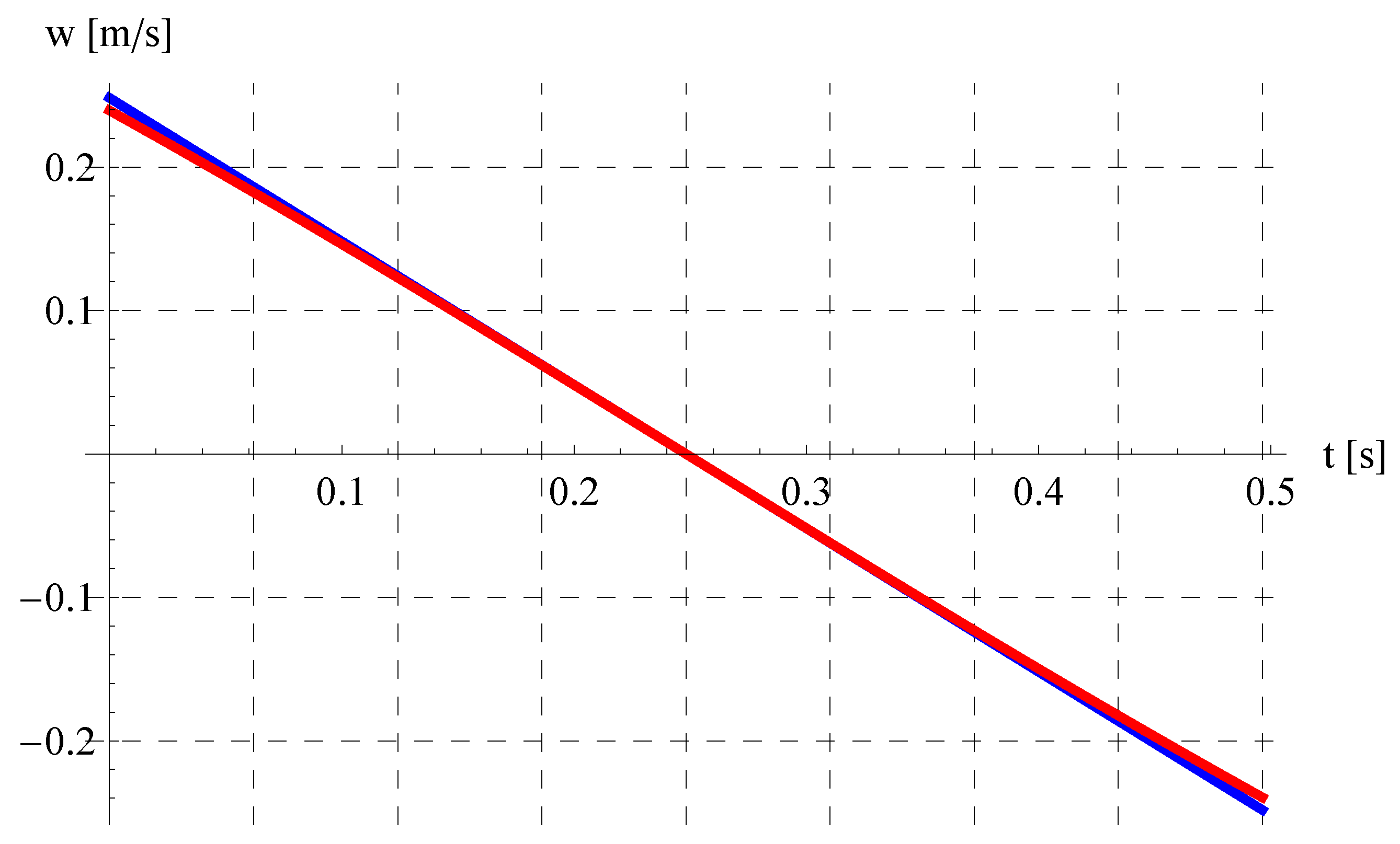
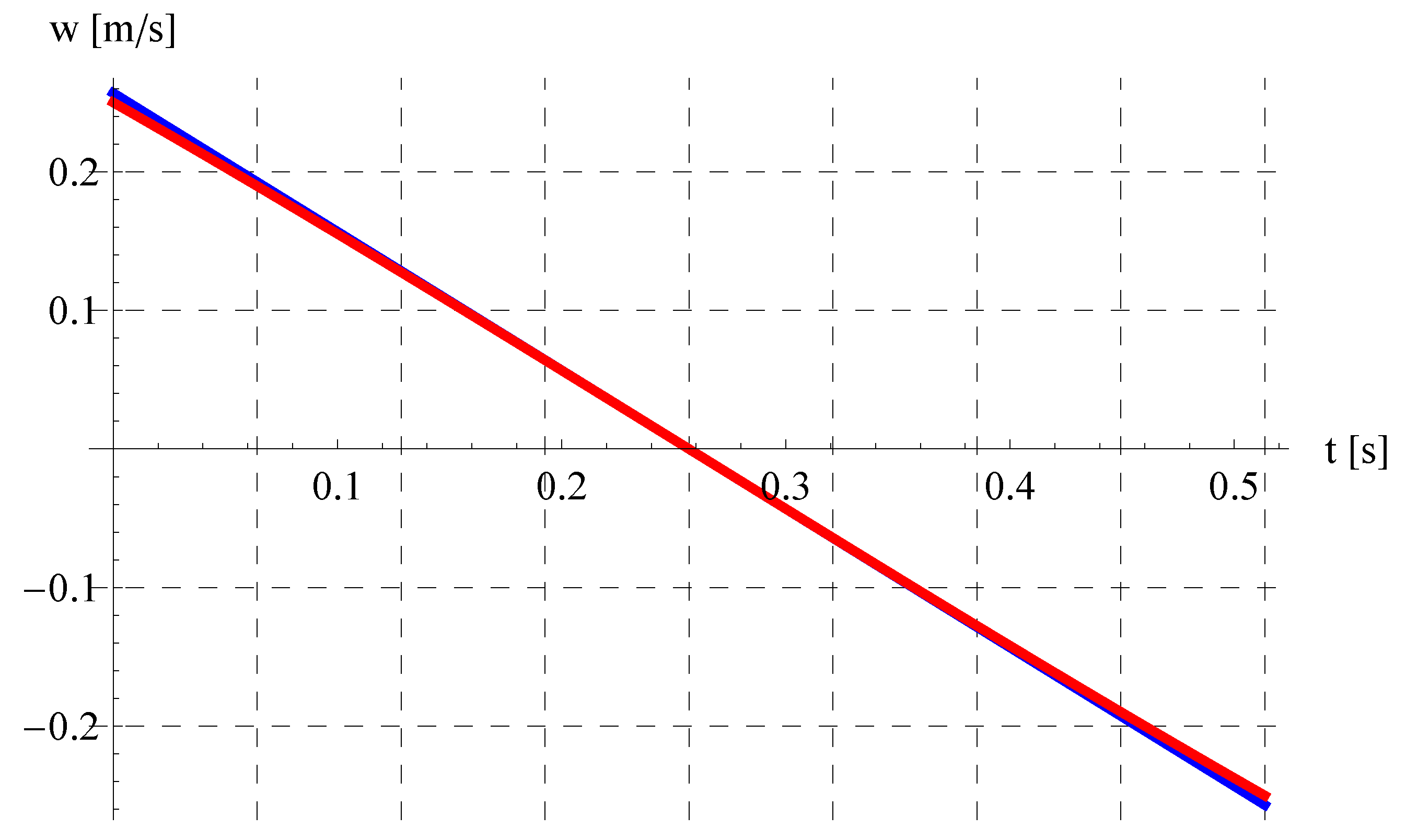
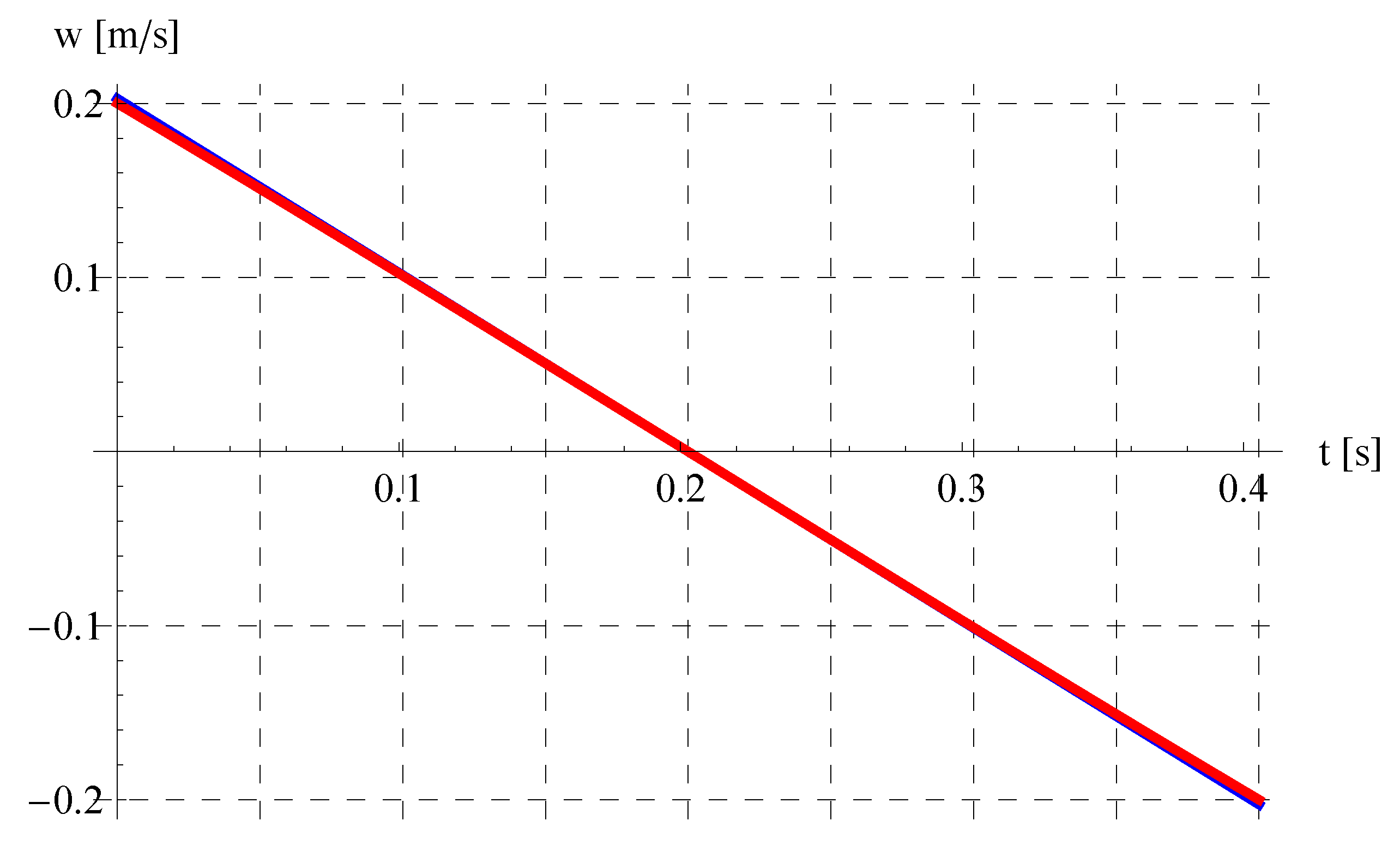
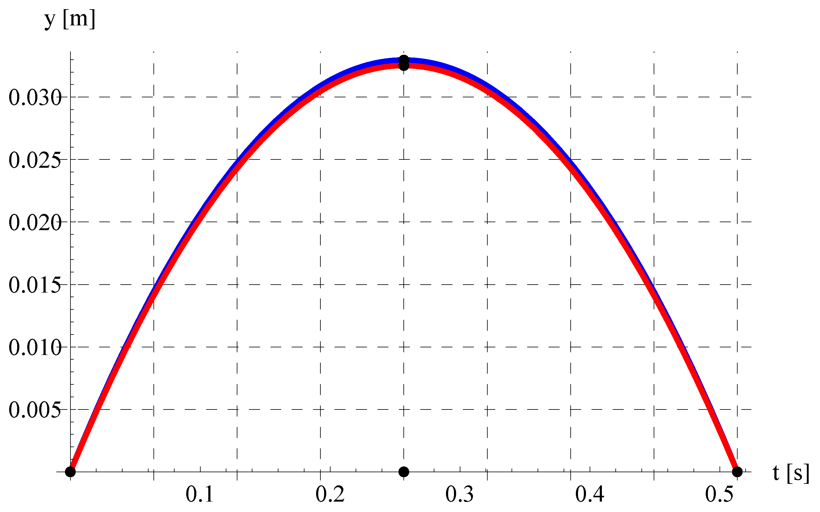
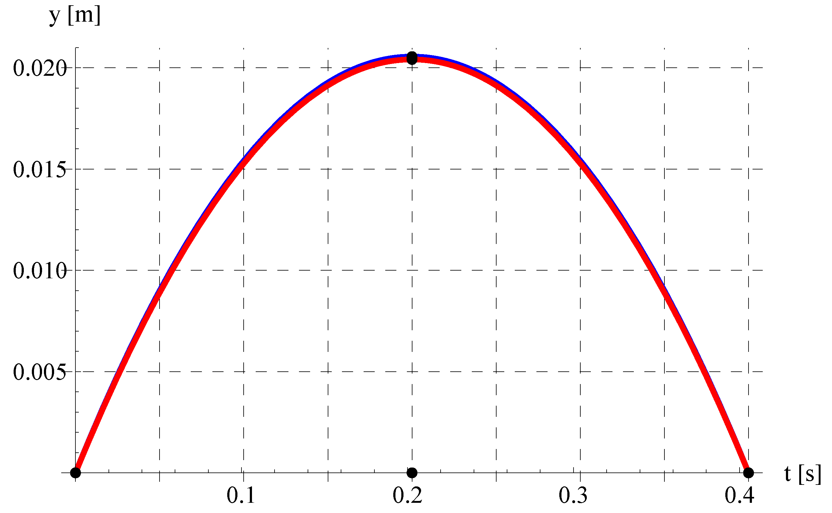
In this discussion, the values of acceleration due to gravity of Earth and speed of light are fixed as g = 9.81 [m/s 2 ] and c = 3 × 10 8 [m/s]. Let us begin the discussion with validating the approximation for the vertical velocity w ( t ) . In Figure 5, Figure 6, Figure 7 and Figure 8, comparisons are performed between the numerical solution of Equation (20) and the present analytic approximation (Equation (21)) for w ( t ) versus time t (in units of c / g ) at different values of v 0 and θ 0 . Agreement is detected in these figures, especially for θ 0 = π / 9 , v 0 = 0.7 c (Figure 6), θ 0 = π / 96 , v 0 = 0.5 c (Figure 7), and θ 0 = π / 2 , v 0 = 0.2 c (Figure 8). Even for the RP with much higher initial velocity v 0 = 0.9 c (Figure 5), the agreement is observed in most of the t-domain. This gives the impression that our analytic approximation for w ( t ) can be trusted. In order to confirm such an impression, further comparisons are performed in Figure 9, Figure 10, Figure 11 and Figure 12 between the numerical solution of Equation (20) and the present approximation (Equation (25)) for y ( t ) (in units of c 2 / g ) versus time t (in units of c / g ) at the same set of values of v 0 and θ 0 in previous figures, Figure 5, Figure 6, Figure 7 and Figure 8. Figure 9 shows a slight difference between the numerical solution using MATHEMATICA and the present analytical approximation at higher velocity v 0 = 0.9 c . This is simply because the value θ 0 = π / 12 lies relatively at the edge of the region of validity of our approximation described in Figure 1. However, the agreement between the numerical solution and the present approximation for y ( t ) can be easily seen in Figure 10, Figure 11 and Figure 12, especially because these figures are produced at the values of v 0 and θ 0 that satisfy the the regions of validity described in Figure 2, Figure 3 and Figure 4.
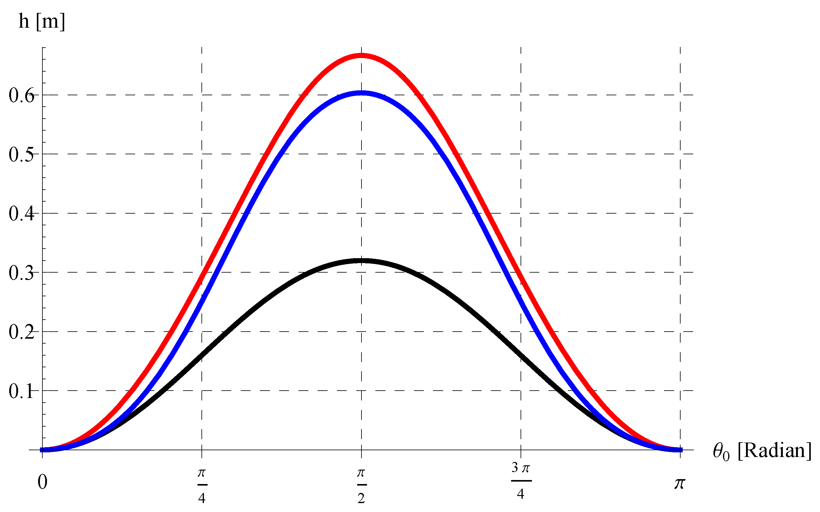
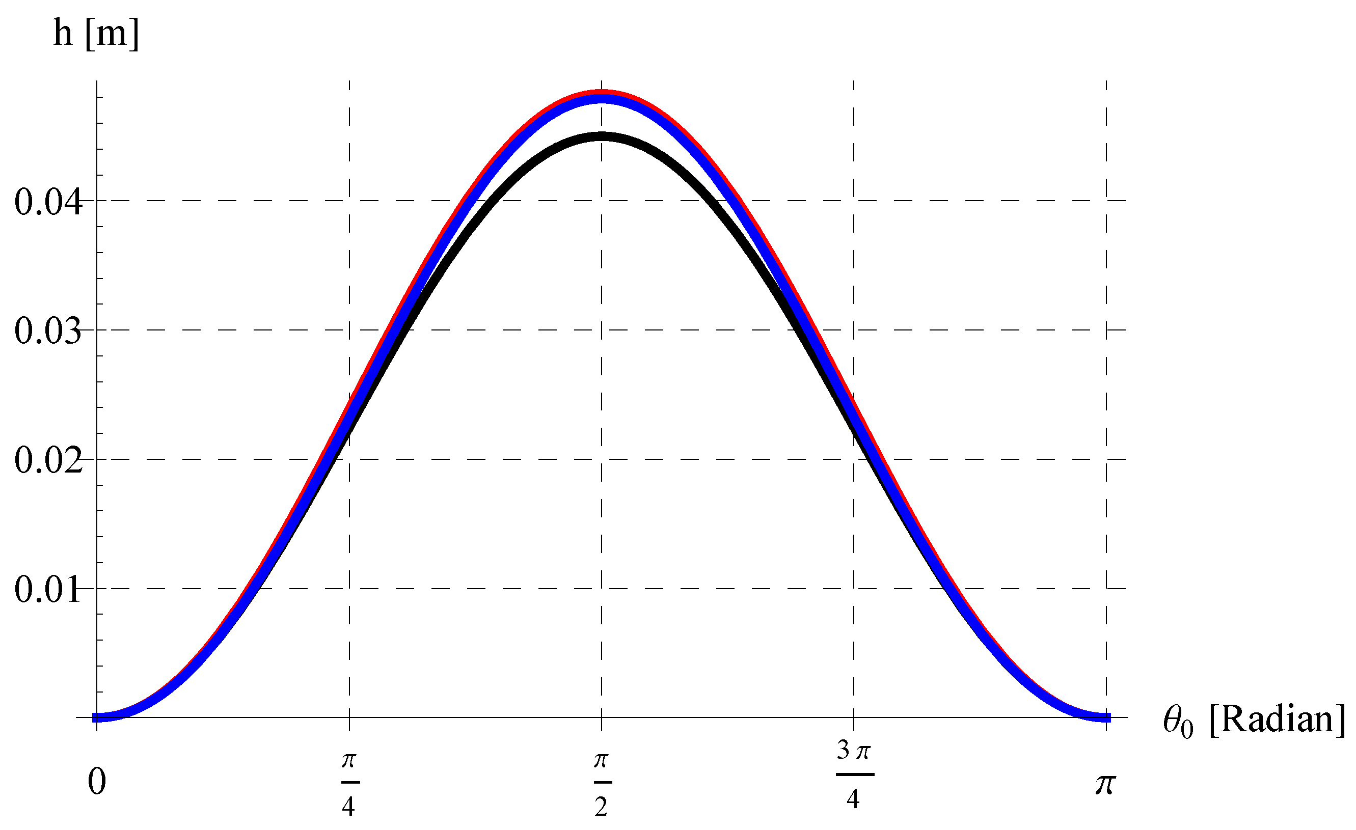
In Figure 13 and Figure 14, the maximum height h (in units of c 2 / g ) is depicted/compared with the corresponding results of the RP in Ref. [15] and the NRP at v 0 = 0.8 c (Figure 13) and v 0 = 0.3 c (Figure 14). In all cases, the h is symmetric about θ 0 = π / 2 (radian) as expected, but both our curve (blue) and the curve (red) of Ref. [15] for the RP are appreciably greater than that of the NRP. However, our curve is lower than the corresponding one of Ref. [15], especially at higher v 0 such as v 0 = 0.8 c in Figure 13. Reasons for such behavior are explained here. Since the instantaneous mass m ( t ) of the RP decreases with motion in the present study, it is always less than the mass m 0 in Ref. [15]), which was taken as a constant during motion. It was theoretically proved that m ( t ) < m 0 t > 0 (see Section 5.6) and confirmed through Figure 15, Figure 16, Figure 17 and Figure 18.
Hence, g m ( t ) > g m 0 and consequently the intensity of the Earth’s gravitational force acting on the RP is higher in our case than in Ref. [15]. This higher intensity of the Earth’s gravitational force affects the RP path and also its maximum height h. Thus, the higher the intensity of the Earth’s gravitational force, the lower the maximum height reached by the RP. As a final note on Figure 14, our curve is closer to Ref. [15] at a relatively lower initial velocity v 0 = 0.3 c . This is because the change in mass is not significant enough in this case. It will be shown later that the present range of the RP is also smaller than the range obtained by the author [15] because of the aforementioned note.
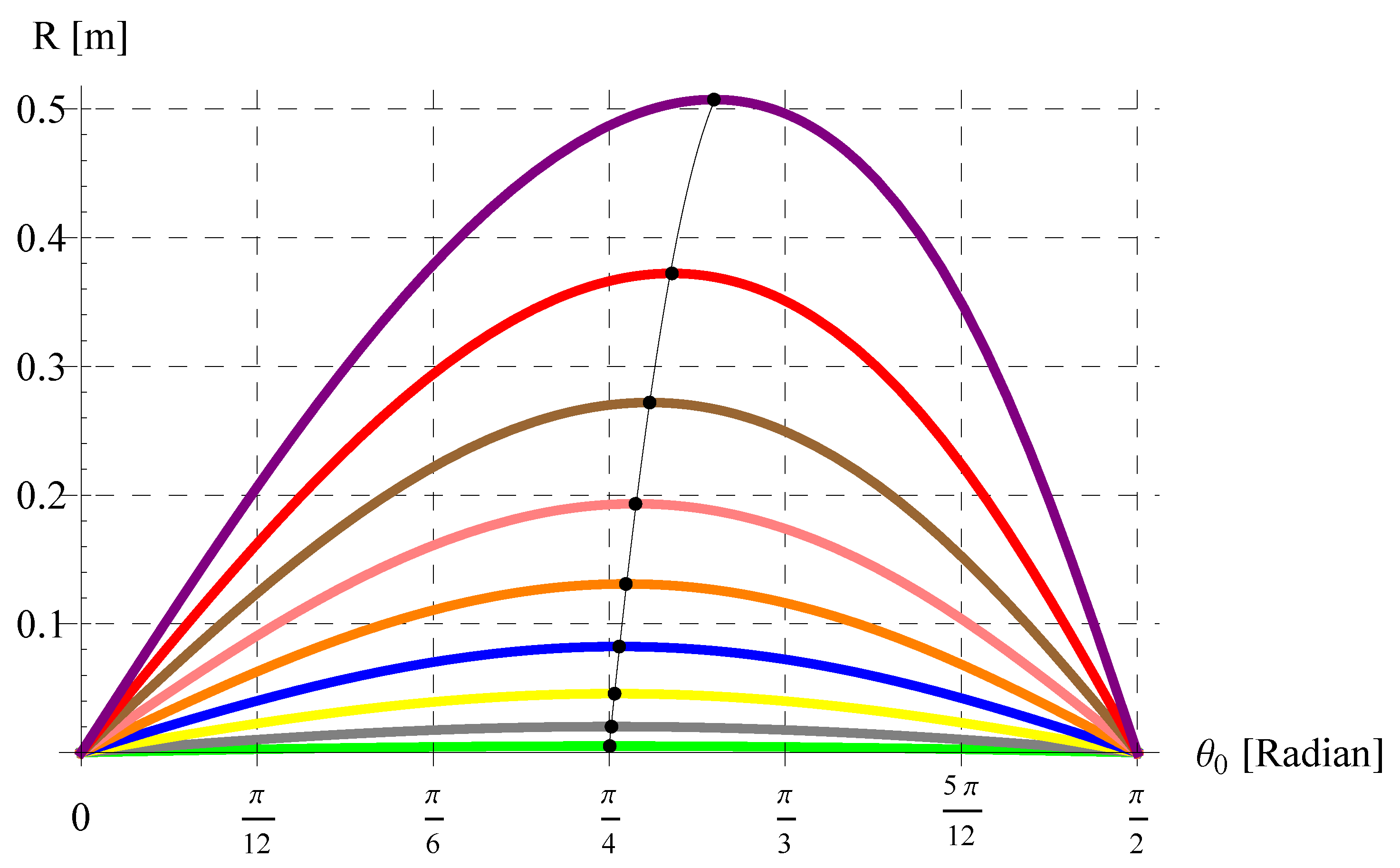
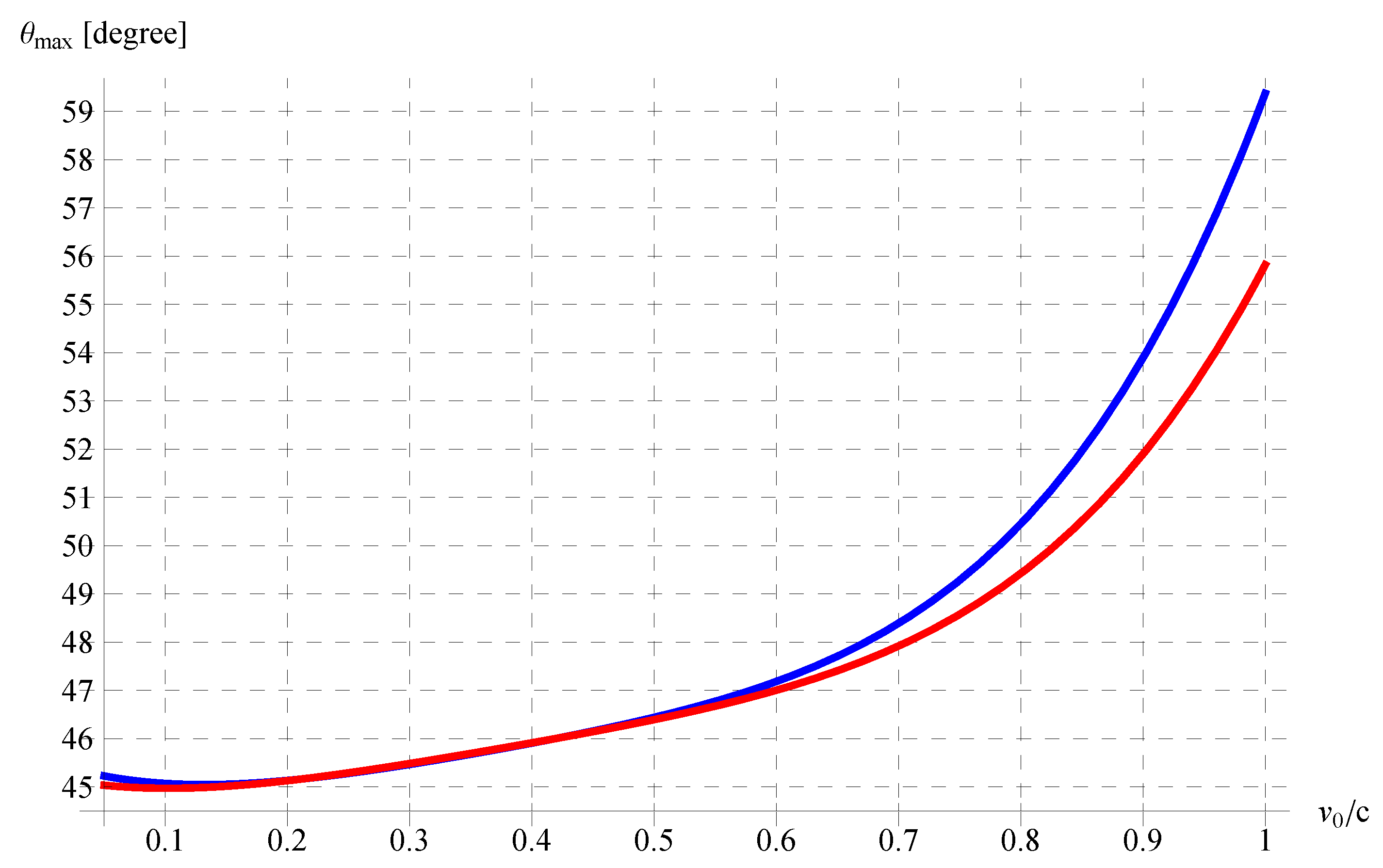
Figure 19 indicates the variation of R against θ 0 at different values of v 0 . It can be seen that R is not symmetric, especially at relatively higher values of v 0 . The symmetry happens in the first two curves from below, i.e., at v 0 = 0.1 c (green) and v 0 = 0.2 c (gray). Above these two curves, the symmetry disappears. In addition, R is maximum when θ 0 = π / 4 for v 0 = 0.1 c (green) and v 0 = 0.2 c (gray). For the rest of the curves, R is maximum at different values of θ 0 in the interval ( π / 4 , π / 6 ) . It can be concluded from this figure that the angle ( θ 0 ) max that maximizes the range R depends on v 0 such that ( θ 0 ) max = π / 4 when v 0 0.2 c while ( θ 0 ) max approaches π / 6 as v 0 approaches c. Such dependence of ( θ 0 ) max on v 0 is depicted in Figure 20. This figure confirms our results above that ( θ 0 ) max [ π / 4 , π / 6 ) .
Comparison between the present trajectory (blue), the corresponding results in Ref. [15] (red), and the non-relativistic trajectory (black) are presented in Figure 21 and Figure 22 at v 0 = 0.5 c , θ 0 = π / 4 (Figure 21) and v 0 = 0.7 c , θ 0 = π / 6 (Figure 22). These figures reveal that the current trajectory (blue) is shows much more curvature than the corresponding one in Ref. [15] (red) for the RP. This is because of the same reasons explained before when discussing the results of the maximum height h in Figure 13 and Figure 14.

7. Conclusions

The model describing the motion of the RP was established in this paper. The model was investigated, taking into account the mass variation. Explicit solutions were obtained for the velocities and displacements in the horizontal and the vertical directions, utilizing fundamental solution methods. The main characteristics of the RP were solved and introduced via analytical formulas. It is concluded that the mass of the RP varies during motion and an analytic formula for instantaneous mass in terms of time was determined. It was declared that the angle of maximum range of the RP depends on the launching velocity v 0 , i.e., unlike the NRP in which the angle of maximum range is always π / 4 . In addition, the angle of maximum range lies in a specific interval [ π / 4 , π / 6 ) based on the given initial velocity v 0 (<c). The obtained results were compared with a previous work in the relevant literature [15]. The difference in results was interpreted and demonstrated. As a validation, the current relativistic results reduced to the corresponding ones of the non-relativistic projectile when the initial velocity is not comparable to the speed of light, i.e., v 0 c . Parametric equations of the RP trajectory were determined analytically. The current analysis can be further extended by incorporating the resistance medium into the motion of the RP as a separate future work. Also, other classical projectile problems in the literature [27,28,29,30,31] can be treated in future via applying the relativistic effect.

Author Contributions

Conceptualization, E.A.A., A.E., E.R.E.-Z. and M.S.A.; Methodology, E.A.A., A.E., E.R.E.-Z. and M.S.A.; Software, H.K.A.-J., M.S.A. and M.A.; Validation, E.A.A., A.E., E.R.E.-Z. and M.A.; Formal analysis, E.A.A., A.E., E.R.E.-Z. and M.A.; Investigation, E.A.A., A.E., E.R.E.-Z. and M.A.; Resources, A.E., H.K.A.-J. and M.A.; Data curation, A.E., E.R.E.-Z., M.A. and H.K.A.-J.; Writing—original draft, E.A.A., A.E., E.R.E.-Z. and M.S.A.; Visualization, E.A.A., A.E., E.R.E.-Z., M.S.A., M.A. and H.K.A.-J. All authors have read and agreed to the published version of the manuscript.

Funding

This study was supported via funding from Prince sattam bin Abdulaziz University project number (PSAU/2023/R/1444).

Data Availability Statement

No new data were created or analyzed in this study. Data sharing is not applicable to this article.

Conflicts of Interest

The authors declare no conflict of interest.

Appendix A. Formulation Using Covariant Equations

Consider a particle of initial mass m 0 moving with velocity v with respect to an inertial frame, say the laboratory frame. Let τ be the instantaneous proper time, measured on a clock which is instantaneously at rest with respect to the particle. Then, the covariant equations in the moving frame of the particle are given by (see [17] (pp. 93–96))
K i = d p i d τ , τ = t β , β = 1 1 v 2 / c 2 ,
where K i is the i’th component of the generalized force, whose four components are expressed as
K 1 = β F x , K 2 = β F y , K 3 = β F z , K 4 = β c 2 F · v ,
p 1 = p x = β m 0 v x , p 2 = p y = β m 0 v y , p 3 = p z = β m 0 v z , p 4 = β m 0 ,
where t is the time measured by laboratory observers using their laboratory clocks, F is the force on the particle, and p i is the i’th component of the momentum. Based on the present physical problem, we have the three components of the force as
F x = 0 , F y = β m 0 g , F z = 0 .
In the x-direction ( i = 1 ), we have from (A1) that β F x = d p x d τ . Since F x = 0 , d p x d τ = 0 , or equivalently, β m 0 d d t ( β u ) = 0 ( v x = u ), i.e., d d t ( β u ) = 0 , which gives
β d u d t + u d β d t = 0 .
We have the derivative
d β d t = β v d v d t c 2 v 2 .
Inserting (A6) into (A5) and simplifying yields
d u d t + u v d v d t c 2 v 2 ,
which is the same equation obtained in Section 2 by Equation (5). Similarly, we can obtain, in the y-direction, that F y = d p y d t , and accordingly,
d d t ( β w ) = β g .
Thus,
d w d t + w v d v d t c 2 v 2 = g ,
which also agrees with Equation (6).

Appendix B. Properties of the NRP: Special Cases of the Current RP

In the NRP, the velocities are not comparable to the speed of light c, i.e., u 0 c , w 0 c , and v 0 c . From calculus, we have
tanh 1 w 0 c = w 0 c + w 0 3 3 c 3 + w 0 5 5 c 5 + .
Since w 0 c , the higher terms in (A10) can be neglected to give
tanh 1 w 0 c w 0 c .
From Equation (38), the time of maximum height T h reduces to
T h = w 0 g = v 0 sin θ 0 g ,
and consequently, the maximum height H becomes
h = 1 2 g w 0 2 g 2 = w 0 2 2 g = v 0 2 sin 2 θ 0 2 g .
Equation (40) yields
T f = 2 w 0 g = 2 v 0 sin θ 0 g ,
which is the same flight time of the NRP. Since E w 0 g , the range R in Equation (41) can be written as
R = u 0 c 2 g c 2 w 0 2 sin 1 w 0 c + w 0 c 1 w 0 2 c 2 ,
or
R = u 0 c 2 g c 2 w 0 2 2 w 0 c ,
= 2 u 0 w 0 g 1 w 0 2 c 2 ,
= 2 v 0 2 sin θ 0 cos θ 0 g ,
where the approximation sin 1 w 0 c w 0 c is applied in Equation (A16). The term w 0 2 c 2 in Equation (A17) is neglected to give Equation (A18) which represents the range of the NRP. The trajectory equation in Equation (43) can be expressed as
2 g x u 0 c 1 w 0 2 c 2 = sin 1 w 0 2 2 g y c + sin 1 w 0 c + w 0 2 2 g y c 1 w 0 2 2 g y c 2 + w 0 c 1 w 0 2 c 2 ,
or
2 g x u 0 c 1 w 0 2 c 2 = sin 1 δ + sin 1 w 0 c + δ 1 δ 2 + w 0 c 1 w 0 2 c 2 ,
where δ = w 0 2 2 g y c . On neglecting the higher terms of w 0 c and applying sin 1 w 0 c w 0 c , we obtain
2 g x u 0 c = 2 w 0 c + sin 1 δ + δ 1 δ 2 .
Since the magnitude w 0 2 2 g y is not comparable to c for any classical velocity w 0 c , δ 1 . Hence, the approximations
sin 1 δ = δ + δ 3 6 + 3 δ 5 40 + δ ,
and
1 δ 2 = 1 δ 2 2 δ 4 8 + 1 ,
can be used. Therefore, Equation (A21) yields
g x u 0 c = w 0 c + δ .
Thus,
g x u 0 w 0 = c δ = w 0 2 2 g y .
Therefore,
y = w 0 x u 0 g 2 u 0 2 x 2 ,
that is,
y = x tan θ 0 g sec 2 θ 0 2 v 0 2 x 2 .
This is also the corresponding trajectory of the NRP.

References

  1. Goldstein, H. Classical Mechanics; Addison-Wesley: San Francisco, CA, USA, 1980. [Google Scholar]
  2. Bedford, A.; Fowler, W. Engineering Mechanics; Addison-Wesley: San Francisco, CA, USA, 1996. [Google Scholar]
  3. Hayen, J.C. Projectile motion in a resistant medium. Part I: Exact solution and prop-erties. Int. J.-Non-Linear Mech. 2003, 38, 357–369. [Google Scholar] [CrossRef]
  4. Hayen, J.C. Projectile motion in a resistant medium. Part II: Approximate solution and estimates. Int. J.-Non-Linear Mech. 2003, 38, 371–380. [Google Scholar] [CrossRef]
  5. Weinacht, P.; Cooper, G.R.; Newill, J.F. Analytical Prediction of Trajectories for High-Velocity Direct-Fire Munitions; Technical report ARL-TR-3567; US Army Research Laboratory: Adelphi, MD, USA, 2005. [Google Scholar]
  6. Yabushita, K.; Yamashita, M.; Tsuboi, K. An analytic solution of projectile motion with the quadratic resistance law using the homotopy analysis method. J. Phys. A Math. Theor. 2007, 40, 8403–8416. [Google Scholar] [CrossRef]
  7. Benacka, J. Solution to projectile motion with quadratic drag and graphing the tra-jectory in spreadsheets. Int. J. Math. Educ. Sci. Technol. 2010, 41, 373–378. [Google Scholar] [CrossRef]
  8. Benacka, J. On high-altitude projectile motion. J. Phys. 2011, 89, 1003–1008. [Google Scholar] [CrossRef]
  9. Ebaid, A. Analysis of projectile motion in view of the fractional calculus. Appl. Math. Model. 2011, 35, 1231–1239. [Google Scholar] [CrossRef]
  10. Ahmad, B.; Batarfi, H.; Nieto, J.J.; Otero-Zarraquinos, O.; Shammakh, W. Projectile motion via Riemann-Liouville calculus. Adv. Differ. Equ. 2015, 2015, 63. [Google Scholar] [CrossRef]
  11. Rosales, J.J.; Guia, M.; Gomez, F.; Aguilar, F.; Martinez, J. Two-dimensional fractional projectile motion in a resisting medium. Cent. Eur. J. Phys. 2014, 12, 517–520. [Google Scholar] [CrossRef]
  12. Garcia, J.R.; Calderon, M.G.; Ortiz, J.M.; Baleanu, D.; de Santiago, C.S. Motion of a particle in a resisting medium using fractional calculus approach. Proc. Rom. Acad. Ser. A 2013, 14, 42–47. [Google Scholar]
  13. Ebaid, A.; El-Zahar, E.R.; Aljohani, A.F.; Salah, B.; Krid, M.; Machado, J.T. Analysis of the two-dimensional fractional projectile motion in view of the experimental data. Nonlinear Dyn. 2019, 97, 1711–1720. [Google Scholar] [CrossRef]
  14. Shahin, G.Y. Features of projectile motion in special theory of relativity. Eur. J. Phys. 2006, 27, 173. [Google Scholar] [CrossRef]
  15. Giffune, T.; Andrews, G. On the Relativistic Motion of Projectiles: On Range and Vertical Height, Undergraduate Research (NCUR) 2016; University of North Carolina Asheville: Asheville, NC, USA, 2016. [Google Scholar]
  16. Price, R.H. Projectiles, pendula, and special relativity. Am. J. Phys. 2005, 73, 433–438. [Google Scholar] [CrossRef]
  17. Katz, R. An Introduction to the Special Theory of Relativity, 1964 D; Van Nostrand Company, Inc.: New York, NY, USA, 1964. [Google Scholar]
  18. Kamel, A.; Ebaid, A.; El-Zahar, E.R.; Chteoui, R.; Seddek, L.F. Mathematical Physics of Time Dilation through Curved Trajectories with Applications. Mathematics 2023, 11, 2402. [Google Scholar] [CrossRef]
  19. Dygert, B.; Kinzel, C.; Junge, M.; Raymond, A.; Slivken, E.; Zhu, J. The bullet problem with discrete speeds. Electron. Commun. Probab. 2019, 24, 1–11. [Google Scholar] [CrossRef]
  20. Junge, M.; San Miguel, A.O.; Reeves, L.; Sánchez, C.R. Non-universality in clustered ballistic annihilation. Electron. Commun. Probab. 2023, 28, 1–12. [Google Scholar] [CrossRef]
  21. Gelfer, E.; Elkina, N.; Fedotov, A. Unexpected impact of radiation friction: Enhancing production of longitudinal plasma waves. Sci. Rep. 2018, 8, 6478. [Google Scholar] [CrossRef]
  22. Dong, P.; Reed, S.A.; Yi, S.A.; Kalmykov, S.; Shvets, G.; Matlis, N.H.; McGuffey, C.; Bulanov, S.S.; Chvykov, V.; Kalintchenko, G.; et al. Formation of optical bullets in laser-driven plasma bubble accelerators. AIP Conf. Proc. 2010, 1299, 171–173. [Google Scholar]
  23. Buck, A. Advanced Characterization and Control of Laser Wakefield Acceleration. Ph.D. Thesis, Ludwig-Maximilians-Universität München, Munich, Germany, 2011. [Google Scholar]
  24. Aharya, S.; Acosta, F.T.; Adamová, D.; Adolfsson, J.; Aggarwal, M.M.; Aglieri Rinella, G.; Agnello, M.; Agrawal, N.; Ahammed, Z.; Ahn, S.U.; et al. Neutral pion and η meson production at midrapidity in Pb-Pb collisions at 2.76 TeV. Phys. Rev. C 2018, 98, 1–28. [Google Scholar]
  25. Carbajo, S.; Granados, E.; Schimpf, D.; Sell, A.; Hong, K.H.; Moses, J.; Kärtner, F.X. Efficient generation of ultra-intense few-cycle radially polarized laser pulses. Opt. Lett. 2014, 39, 2487–2490. [Google Scholar] [CrossRef]
  26. Carbajo, S.; Nanni, E.A.; Wong, L.J.; Moriena, G.; Keathley, P.D.; Laurent, G.; Miller, R.D.; Kärtner, F.X. Direct longitudinal laser acceleration of electrons in free space. Phys. Rev. Accel. Beams 2016, 19, 21303. [Google Scholar] [CrossRef]
  27. El-Zahar, E.R.; Ebaid, A.; Aljohani, A.F.; Tenreiro Machado, J.; Baleanu, D. Re-Evaluating the Classical Falling Body Problem. Mathematics 2020, 8, 553. [Google Scholar] [CrossRef]
  28. Ebaid, A.; Alharbi, W.; Aljoufi, M.D.; El-Zahar, E.R. The Exact Solution of the Falling Body Problem in Three-Dimensions: Comparative Study. Mathematics 2020, 8, 1726. [Google Scholar] [CrossRef]
  29. Escobar, I.; Arribas, E.; Ramirez-Vazquez, R.; Belénde, A.Z. Projectile motion revis-ited: Does the distance between the launcher and the object always increase? J. King Saud Univ. Sci. 2022, 34, 101842. [Google Scholar] [CrossRef]
  30. Bradshaw, J.L. Projectile motion with quadratic drag. Am. J. Phys. 2023, 91, 258–263. [Google Scholar] [CrossRef]
  31. Said, A.; Mshewa, M.; Mwakipunda, G.; Ngata, M.; Mohamed, E. Computational Solution to the Problems of Projectile Motion under Significant Linear Drag Effect. Open J. Appl. Sci. 2023, 13, 508–528. [Google Scholar] [CrossRef]
Figure 1. Behavior of ϵ ( v ) and σ ( v ) versus θ at v = 0.9 c .
Mathematics 11 03890 g001
Figure 2. Behavior of ϵ ( v ) and σ ( v ) versus θ at v = 0.7 c .
Mathematics 11 03890 g002
Figure 3. Behavior of ϵ ( v ) and σ ( v ) versus θ at v = 0.5 c .
Mathematics 11 03890 g003
Figure 4. Behavior of ϵ ( v ) and σ ( v ) versus θ at v = 0.2 c .
Mathematics 11 03890 g004
Figure 5. Comparison between the numerical solution (red) of Equation (20) and the present analytic approximation (blue) for w ( t ) (Equation (21)) at θ 0 = π / 12 and v 0 = 0.9 c .
Mathematics 11 03890 g005
Figure 6. Comparison between the numerical solution (red) of Equation (20) and the present analytic approximation (blue) for w ( t ) (Equation (21)) at θ 0 = π / 9 and v 0 = 0.7 c .
Mathematics 11 03890 g006
Figure 7. Comparison between the numerical solution (red) of Equation (20) and the present analytic approximation (blue) for w ( t ) (Equation (21)) at θ 0 = π / 6 and v 0 = 0.5 c .
Mathematics 11 03890 g007
Figure 8. Comparison between the numerical solution (red) of Equation (20) and the present analytic approximation (blue) for w ( t ) (Equation (21)) at θ 0 = π / 2 and v 0 = 0.2 c .
Mathematics 11 03890 g008
Figure 9. Comparison between the numerical solution (red) and the present analytic approximation (blue) for y ( t ) (Equation (25)) at θ 0 = π / 12 and v 0 = 0.9 c .
Mathematics 11 03890 g009
Figure 10. Comparison between the numerical solution (red) and the present analytic approximation (blue) for y ( t ) (Equation (25)) at θ 0 = π / 9 and v 0 = 0.7 c .
Mathematics 11 03890 g010
Figure 11. Comparison between the numerical solution (red) and the present analytic approximation (blue) for y ( t ) (Equation (25)) at θ 0 = π / 6 and v 0 = 0.5 c .
Mathematics 11 03890 g011
Figure 12. Comparison between the numerical solution (red) and the present analytic approximation (blue) for y ( t ) (Equation (25)) at θ 0 = π / 2 and v 0 = 0.2 c .
Mathematics 11 03890 g012
Figure 13. Comparison between the present maximum height for RP (blue), the corresponding results in Ref. [15] (red), and the NRP (black) at v 0 = 0.8 c .
Mathematics 11 03890 g013
Figure 14. Comparison between the present maximum height for RP (blue), the corresponding results in Ref. [15] (red), and the NRP (black) at v 0 = 0.3 c .
Mathematics 11 03890 g014
Figure 15. Plots of the relativistic factor of mass γ ( t ) versus time t at v 0 = 0.99 c and θ 0 = π / 15 .
Mathematics 11 03890 g015
Figure 16. Plots of the relativistic factor of mass γ ( t ) versus time t at v 0 = 0.8 c and θ 0 = π / 12 .
Mathematics 11 03890 g016
Figure 17. Plots of the relativistic factor of mass γ ( t ) versus time t at v 0 = 0.3 c and θ 0 = π / 6 .
Mathematics 11 03890 g017
Figure 18. Plots of the relativistic factor of mass γ ( t ) versus time t at v 0 = 0.1 c and θ 0 = π / 4 .
Mathematics 11 03890 g018
Figure 19. Variation of R against θ 0 at v 0 = 0.1 c (green), v 0 = 0.2 c (gray), v 0 = 0.3 c (yellow), v 0 = 0.4 c (blue), v 0 = 0.5 c (orange), v 0 = 0.6 c (pink), v 0 = 0.7 c (brown), v 0 = 0.8 c (red), and v 0 = 0.9 c (purple). The thin curve (black) passes through the points of maximum range.
Mathematics 11 03890 g019
Figure 20. Comparison between the present (blue) maximum angle ( θ 0 ) max and the corresponding results in Ref. [15] (red) at different values of v 0 / c .
Mathematics 11 03890 g020
Figure 21. Comparison between the present trajectory (blue), the corresponding results in Ref. [15] (red), and the non-relativistic trajectory (black) at v 0 = 0.5 c and θ 0 = π / 4 .
Mathematics 11 03890 g021
Figure 22. Comparison between the present trajectory (blue), the corresponding results in Ref. [15] (red), and the non-relativistic trajectory (black) at v 0 = 0.7 c and θ 0 = π / 6 .
Mathematics 11 03890 g022
Disclaimer/Publisher’s Note: The statements, opinions and data contained in all publications are solely those of the individual author(s) and contributor(s) and not of MDPI and/or the editor(s). MDPI and/or the editor(s) disclaim responsibility for any injury to people or property resulting from any ideas, methods, instructions or products referred to in the content.