1. Introduction
Robots are key for the automation of various tasks and have revolutionized many fields in the 21st century. They are extremely precise and efficient in doing tasks that otherwise would be difficult or impossible. One such type of robot that is becoming increasingly important is a cleaning robot, which is programmed to work in indoor environments [
1,
2,
3]. These robots have vast potential to enhance productivity in cleaning tasks in domestic and commercial settings and have witnessed a steep rise over the last two decades. It is estimated that between 2015 and 2018, about
million robotic cleaning units were sold worldwide [
4].
Indoor robots (for cleaning and/or logistics) are designed for fully autonomous traversal in indoor environments [
1]. Typical indoor traversal requires the robot to be able to avoid obstacles by integrating the sensing models and communication modules [
5,
6]. However, if the environment is multi-floored, the robot is required to have the ability to detect and localize the staircases in order to perform cleaning tasks on the staircase and reach the next floor. Conventional indoor cleaning robots are usually designed for single-floor operations, i.e., they cannot climb the stairs and reach the next floor. However, many real-world indoor environments (residential and commercial buildings) have multiple floors connected by staircases. The stairs may be of different types, e.g., straight, spiral, and L-shaped staircases, and of different materials as well. This severely limits the ability of a conventional cleaning robot to be effective in such scenarios.
The significance of stair-climbing robots has been realized in modern buildings in domestic as well as commercial settings, such as malls, offices, schools, factories, etc. Conventional floor-cleaning robots without stair-climbing capabilities have limited usage in such cases. Stair-climbing robots can detect and localize the staircase and plan its path to climb the stairs and reach the next floor. A single robot can perform cleaning tasks on multiple floors as well as on staircases connecting these floors, thus making them more versatile, efficient, and cost-effective. In summary, the significance of stair-cleaning robots lies in their ability to provide convenience, efficiency, safety, and consistency in cleaning staircases. They offer practical solutions for both residential and commercial environments, making the maintenance of stairs easier and more effective.
To enable robots to traverse staircases, the accurate detection and location of staircases is highly critical. This would enable robots to plan and navigate through such environments, thereby making them much more effective for real-world indoor environments.
Recognizing a staircase seems straightforward for humans. However, for robots to be able to detect, recognize, and localize the staircases, this task is much more complex and challenging. For this, robots should be able to analyze incoming images and detect and recognize stair-like structures, among many other objects, in the working environment. Furthermore, accurate knowledge of the location of the staircase and the angle of approach is very important for reaching and aligning the robot with the staircase in order to start climbing it. This makes staircase detection and localization a highly challenging task for fully autonomous robots.
In this article, we present a solution to work with the sTetro platform [
7] for object detection tasks in real time. sTetro is a small, reconfigurable cleaning robot that can change its shape to climb staircases autonomously. In previous work, we validated the sTetro robot with respect to area coverage by benchmarking its performance with a fixed morphology robot. The results indicated that the sTetro robot could achieve superior coverage performance through its shape-shifting ability. However, the validation was conducted by passing manual commands to navigate the robot toward the first-step position of the staircase, and there were no autonomous strategies applied. In this paper, we extend our previous works by integrating the sensing modules and manipulation modules with sTetro robot using an ROS middleware environment that enables the robot to navigate autonomously to the staircase. For this, we use a deep learning approach to detect and recognize staircases in the incoming image stream. However, the robot also requires knowledge of how to move based on the staircase position/location. To this end, after detecting staircases, the next step is to localize the stairs with respect to the robot. For this, we use our own developed contour detection algorithm to find the target point (center of the first step of the staircase) and angle of approach. This enables the robot to approach the center of the staircase, align itself to the first stair, and then start climbing.
This article proposes a real-time staircase detection and localization for a low-cost stair-climbing robot (sTetro) with limited computing resources onboard. Toward achieving this aim, the following contributions are made:
A client-server computational framework for real-time object detection and motion control with ROS middleware for embedded-system-based small robots.
A contour-based algorithm for calculating the staircase’s middle point and angle of approach from the current position of the robot.
Tests in real environments with motion control of the robot [
8].
The rest of this article is organized as follows:
Section 2 describes the related work. In
Section 3, the technical details of the major components of the proposed system are presented. The experimental setup is given in
Section 4, and the experimental results are presented and discussed in
Section 5. Finally,
Section 6 concludes this article with some future work proposed in this direction.
2. Related Work
Many different approaches have been proposed in the literature to address the problem of staircase detection. These approaches can be grouped based on the sensors and algorithms used. Standard sensors, like RGB and RGB-D, have been used for staircase detection, with the prominent approach of detecting parallel lines in the image [
9]. Though this type of algorithm works for many simple scenarios, they have many limitations. Hough transform [
10], the preferred approach for the detection of parallel lines in traditional computer vision methods, fails to detect staircases that are curved or spiral. Furthermore, these algorithms assume that the robot is parallel to the staircase and facing it. However, this is not the case for most real-world scenarios. The robot must be able to detect and then plan its approach to the staircase. These approaches are also not designed for staircase-climbing robots. These robots require alignment with the staircase, which requires data pertaining to the first step of the staircase. Other approaches using RGB or RGB-D cameras include using Gabor filters, 3D column maps [
11], etc. These are able to handle approaching staircases from different angles. Even LiDARs have been used for the detection of staircases [
12,
13,
14]. However, these approaches also assume that the robot is parallel to the staircase and facing it. Some other sensors that have been used are monocular [
15,
16,
17,
18] and stereo sensors [
19]. In the aforementioned approaches, there is a research gap for real-time staircase detection and localization from arbitrary viewpoints for low-cost mobile robot applications, for example, cleaning and logistic robots.
Object detection and classification using convolutional neural networks (CNN) have been researched intensively in recent decades and have set a revolutionary era in many diverse applications with different kinds of input data, e.g., one such application of CNN using acoustic emission data to predict the roughness of surfaces is given in [
20,
21]. The use of object detection with CNN models has many exciting applications in robotics [
22,
23,
24]. Deep learning using large neural networks can find the unique features of various objects automatically, thereby reducing the need for pre-defined kernel-based solutions. Since the features of the objects can be identified, the most significant achievement of these deep-learning-based methods is the ability to identify uncanny features in object classification. As a result, the effectiveness and accuracy of deep-learning-based methods outperform conventional computer vision methods significantly [
25]. However, the biggest challenge is training these large networks, as they require a large amount of computation to converge by estimating the various parameters defined in the network. Recently, technologies in parallel computing, such as Compute Unified Device Architecture (CUDA) [
26] and NVIDIA CUDA deep neural network (CuDNN) [
27], have enabled parallel computing using multiple threads to process large calculations in separate graphic cards with their own graphic processing unit (GPU). Consequently, the training time of these networks has reduced sharply. However, real-time deployment of these deep learning approaches in low-cost and compact embedded controllers is still a big challenge for commercial applications. However, with the dawn of IoT devices, using a server-client framework has reduced the computation load on embedded systems and made it practical to use deep learning models in many real-time applications.
There are many advantages to using deep learning for staircase detection. The model can be trained to detect different types of staircases, including spiral and curved, which proves to be very difficult for standard algorithms. Furthermore, they can be trained to recognize staircases from different angles. This eliminates the need for the robot to be in front of the staircase. These models are highly accurate as well. This is because these models learn the features from data rather than specifying them in the algorithm. Recently, the advances in object detection, including object localization and object classification, are driven by the success of state-of-the-art-convolution network (ConvNet)-based object detectors called the region-based convolutional network method (RCNN) [
28]. The issue with deep learning approaches is the computation power required to run these models in real-time. However, with the recent update to MobileNets [
29,
30] and the release of single-shot multi-box detectors (SSDs) [
31], these models are now capable of running in real-time on low-cost hardware. We also compute the target point and the angle of approach, which allows the robot to align itself with the center of the staircase, thereby having enough space to be able to climb the staircase.
3. Methodology
In this section, we describe the details of our proposed system of real-time staircase detection and localization for stair-cleaning robotic applications.
3.1. ROS-Based Client–Server Computational Framework
It is well known that neural networks have large computation costs. Due to this, the implementation of CNN models on low-cost low-powered hardware in real time is almost impossible. Hence, we propose a client-server model for real-time applications. The proposed system is built in the ROS environment [
32]. ROS provides the infrastructure and mechanism for ROS modules. The ROS master installed on the remote server monitors the entire ROS ecosystem. An ROS-based block diagram of the proposed system using a client-server model is shown in
Figure 1.
The robot itself has a small single-board computer (SBC) onboard, and it is connected to a larger, powerful computer (e.g., mid-range laptop or desktop: remote server) off-board that acts as both a “base station” as well as a development machine. The SBC processes the raw sensor data into ROS-compatible messages and transmits them over the network to the base station, which is running ROS. The base station uses these incoming data to compute the appropriate motion commands and send them back over the network to the robot. The onboard SBC will then convert these into signals to send to the motor driver to move the robot. This “base station” PC is also used as a development machine to run CNN models, process input image data, visualize the data, and run algorithms in real-time, as described below.
The ROS topics transmitted to the ROS network through WiFi or data networks enable communication between ROS nodes. Specifically, first, the perception client uses an image sensor to extract an image from the image stream through the node and send it over to the server running ROS. The server uses two steps to detect and localize staircases. The first step involves the detection of staircases. This includes extracting features from an RGB image using MobileNet architectures. We then classify and predict a bounding box using the SSD architecture. This is conducted in the node.
The second step has two components: The detection of the first step of the staircase. This is conducted in the node. The stair’s first-step information is then passed to the next node in ROS, the node, which is used to detect the target point, , a point close to the center of the first step. The angle of approach, , is also computed in this step. We then send this information to the portion of the client responsible for robot movement. Based on the angle of approach, we decide on a movement strategy, e.g., move forward, left, or right. This movement command is executed by the onboard microcontroller with the help of actuators (DC motors) on robot wheels. For the next cycle, the perception client feeds the ROS server with new input image data. This process is repeated until the target point is reached.
3.2. Feature Extraction Using MobileNets
Specialized CNN-based architectures like MobileNets [
29,
30], AlexNet [
33], Inception [
34], ResNet [
35], etc., are highly accurate at classifying images. The recently proposed Inception-ResNet [
36] has the highest accuracy. However, we use the MobileNet architecture due to its low computation cost, which allows for real-time image classification on mobile hardware [
37]. The MobileNet is an architecture model of the CNN that explicitly focuses on image classification for real-time applications. Rather than using the standard convolution layers of CNN, it uses depthwise separable convolution layers, which makes it much more efficient than contemporary CNN architectures. This reduces the computational cost and requires very low computational power to run or apply transfer learning (note that by using transfer learning, we do not need to build a CNN model from scratch). Specifically, we use MobileNetv2 [
30], which is an improvement over the standard MobileNet [
29]. The basic blocks of both architectures are shown in
Figure 2. The extracted features of MobileNet are used by SSD architecture to classify and localize the staircases. The structure of SSD is discussed in the next section.
3.2.1. Mobilenet Architecture
For computer vision tasks, CNN models are extensively used nowadays. One specialized CNN-based architecture, MobileNet, uses so-called depthwise separable convolutions instead of conventional convolutional layers. Note that in 2D convolutions, the 2D convolution operation is performed over all input channels, whereas in depthwise convolution, each channel is kept separate. This reduces the huge computation burden on the CNN model for real-time classification tasks.
The MobileNet architecture consists of a single convolution layer followed by the batch norm and a modified rectified linear unit (ReLU). The convolution layer is split into a depthwise convolution and a pointwise convolution. The input data are filtered by the depthwise convolution and the pointwise convolution layer combines the features created by the depthwise convolution to create new features.
One of the main innovations in MobileNet is depthwise separable convolution, which is formed by depthwise and pointwise convolutions together. The traditional convolution kernel is split into two kernels by the separable convolution, e.g., a
kernel is split into two kernels of size
and a
. This separation reduces the number of operations needed to perform the convolution and is, therefore, much more efficient. Therefore, we obtain approximately the same output as with conventional convolution layers but at a much faster rate with the same accuracy. A regular
convolution layer is the input layer in a full architecture of MobileNet V1, followed by 13 times the “depthwise separable” convolution block. In between these depthwise separable blocks in the MobileNet architecture, there are no pooling layers. Furthermore, to enhance the efficiency of MobileNet, an improved version of the activation function, named ReLU6, is used, with an upper limit of 6 to the conventional ReLU function. Equation (
1) is used to compute the improved activation function,
[
38].
where
x is the input. One building block structure of MobileNet V1 and V2 are illustrated in
Figure 2.
3.2.2. MobilenetV2 Architecture
The next version of MobileNets is named MobileNetV2, and its main building block is shown on the right-hand side of
Figure 2. There are three convolution layers in the bottleneck residual block.
Expansion layer: The first
expansion layer expands the input data and increases the number of channels. The data are expanded based on the expansion factor, which is a hyperparameter of an architecture. The default expansion factor is 6.
Depthwise convolution layer: The second layer is the depthwise convolution layer, which is the same as in MobileNetV1.
Projection layer: In MobileNetV2, contrary to MobileNetV1, the
pointwise convolution makes the number of channels smaller. This is known as the projection layer. This layer is also called the bottleneck layer since it reduces the amount of data flowing through it [
38]. It does the opposite of the projection layer. Some of the parameters of the models used in this work are given in
Table 1.
3.3. Localization Using Single-Shot Multibox Detector (SSD)
Though CNN-based architectures with fully connected layers can be used to classify images and detect staircases, autonomous traversal requires the knowledge of the location of the staircase as well. For this, we need a bounding box over the staircase to calculate its position, which is required for calculating the target point and the angle of approach. For this purpose, object localization techniques such as single-shot multibox detector (SSD) [
31], faster R-CNN [
39], YOLO [
40], etc., can be used. These use the features extracted from CNN-based architectures to classify and localize objects. Generally, faster R-CNN is the preferred method for object localization due to the best accuracy. However, SSDs have been shown to perform better in most scenarios for large objects, which is the case for staircases [
37]. SSD is also extremely fast since it requires only one forward pass for the computation of all bounding boxes. Due to these reasons, SSD is highly appropriate for the current scenario.
The SSD algorithm divides the image using a grid, and each grid cell is responsible for detecting objects in that region of the image, instead of using a sliding window, as in RCNN. Object detection means predicting the class and location of an object within that region. If there is no object present in that grid, we consider it as the background class. For instance, we use a grid cell in this work, and each grid cell is able to output the position and shape of the object (staircase, not staircase) it contains.
3.3.1. SSD Architecture
SSD passes the input through multiple convolution layers. These layers progressively decrease in size. Each of these layers generates a fixed set of predictions. This enables predictions of various sizes. In addition to this, SSD uses a set of bounding boxes (a.k.a anchor box) of different dimensions. These anchor boxes are pre-defined, and each one is responsible for size and shape within a grid cell. The SSD architecture allows pre-defined aspect ratios of the anchor boxes to account for the shapes of objects, with some longer and some wider, to varying degrees.
Further, these anchor boxes can be scaled up or down with respect to each grid cell in order to find smaller or larger objects within a grid cell. The zoom parameter is used to specify how much the anchor boxes need to be scaled up or down with respect to each grid cell.
These bounding boxes are applied to the predictions from different layers, which allows for predictions of boxes of different sizes and scales. Although the bounding boxes may not be pixel-perfect, the loss in accuracy is found to be very minimal. However, due to this, the performance is drastically increased.
3.3.2. Loss in SSD Training
Since SSD involves predicting a bounding box along with the class for an object, typical loss computation cannot be followed. Loss in SSD training is a weighted sum of loss due to two aspects: confidence and localization. Equation (
2) is used for computing total loss,
L.
where
N is the number of matching boxes and
is the weight term that balances the confidence loss,
, and localization loss,
. Confidence loss is the loss that occurs due to classification. This is computed as the softmax of confidence over multiple classes. Localization loss is the loss in predicting the bounding box of the object. This is computed as a smooth,
, loss between the predicted box and the marked box.
3.3.3. Loss Optimization
We use the root mean square propagation (RMS prop) [
41] algorithm to optimize the total loss during training. Equations (
3)–(
5) represent the RMS prop algorithm at any time
t.
where
is the gradient along weight
.
is the weight at any time
t.
is the exponential average of gradients.
is the initial learning rate.
is a hyperparameter to be tuned.
is constant with a value close to zero to avoid dividing by zero errors.
3.4. First-Step Detection
Through SSD and MobileNets, we are able to detect the staircase and predict a bounding box over it. Here, we require knowledge of the first step to determine the target point and angle of approach. We do this by analyzing the staircase inside the bounding box. These values enable a sTetro robot to move toward the detected staircase autonomously. For the detection of steps, the prominent method is Hough transform [
42], which detects straight lines. However, the steps of staircases may be curved as well. Traditional contour detection is difficult to handle in this situation. Furthermore, we do not need to detect all the contours in the image, as we require only the first step in the calculations. The proposed method for the first step of staircase detection can be divided into two parts. First, we detect edges using Canny edge detection, which is followed by contour detection.
3.4.1. Edge Detection
To be able to detect the first step in the image, we first need to detect edges present in the image. For this, we use the Canny edge detection algorithm [
43] to enhance the accuracy of detected edges; the Canny edge algorithm is divided into four steps: the Gaussian filter step to remove noise, gradient calculation to find the edge pixel candidates, non-max suppression steps to remove the edges with the weak gradient responses, and the hysteresis thresholding step to thin the detected edge lines. This returns an edge representation of the image, i.e., only the pixels that constitute edges are positive. Other pixels are 0.
3.4.2. Contour Detection Algorithm
We propose a contour detection algorithm for determining the first step as the following Algorithm 1. Specifically, all points within a certain distance and certain bounds while giving preference to the points along the direction of the most recent detected points are determined.
Algorithm 1 contains the pseudocode of the algorithm used for first-step detection. Before computation, we generate
, which is the Canny edge representation of the image. We use two functions for this algorithm. The function
returns the contour representing the first step of the staircase. This function uses
to generate a contour representing the first step. It checks the image from bottom to top (represented by
i) and left to right (represented by
j) directions. If an edge point is detected, it calls
, with a contour consisting of only the point,
. Finally, it returns the contour only if its horizontal length is greater than a certain threshold,
. We set this to
of the width of the staircase during experiments. This is conducted using
, which obtains the difference between the horizontal bounds of the contour.
| Algorithm 1 Contour detection algorithm pseudocode. |
function getContour() while do while do contour = getContourWithIJ if then return function getContourWithIJ(canny, i, j, contour) while do for do if then return
getContourWithIJ if then return getContourWithIJ if then while do for do if then return getContourWithIJ if then return getContourWithIJ if then return
|
The function
finds the remaining contour from the reference point,
, in
. This is merged with the contour detected prior to this point, which is represented by
. This consists of four steps to identify the next point in the contour. First, the equation of the line that fits the previous five points in the contour is generated. The function
does this using a line-fitting linear regression approach [
44]. We also set a bound on the slope of the line.
represents this line equation.
represents the slope of this line. Next, we check all points within a range of
X coordinates, represented by variable
t. This variable is bound by a threshold,
. Using this, we compute
, which is the next possible location of the edge. We push this onto an array,
. Then, for each element in
, we search both above and below the elements. If any of them is part of an edge, then we call
with the coordinates of this point. If the top and bottom of this element exist at the boundary, computed using an angle threshold,
, the element is removed from the array.
The working of an algorithm for three different scenarios based on the slope of
is shown in
Figure 3. In this figure, each box represents one pixel in the image. The value in each box represents the iteration in which they would be visited. The box with value
represents the current pixel on which
is called. The line represents the slope for the given scenario, with the value of the slope given below each figure. The algorithm clearly gives preference to points along the slope while also examining points in the area bounded by
. The numbers in boxes represent which iteration of the algorithm would evaluate those pixels. For two pixels having the same iteration number, the one that is closest to the slope will be evaluated first.
3.5. Determining the Target Point
Since we have the contour representing the first step, determining the target point, (approximate central position of the first step of the staircase), is rather simple. We can find n points that are closest to the horizontal center. The distance here is the linear distance between the X-coordinates since there would not be multiple points with the same X-coordinate. We can then fit a line through these points and predict the Y-coordinate of the horizontal center. The horizontal point, x, along the X-coordinate and vertical point, y, along the Y-coordinate give the central target point, . The slope of this line is the angle of approach (). This is necessary so that the robot can rotate itself to align with the staircase. In general, negative angles mean the robot is located to the right of the staircase and should rotate clockwise while moving left so that the robot will become aligned with the staircase. Similarly, positive angles mean the robot is located to the left of the staircase and should rotate counter-clockwise while moving right. Angles close to zero mean the robot is already aligned with the staircase. We use a small threshold around zero to accommodate for slight variations, which may occur during detection.
4. Experimental Setup
In this section, we discuss the dataset specification and specification of the models used. The dataset was generated by capturing images of different staircases using an RGB camera. Details of this are discussed below. The weights of the network were initialized to the weights of a network trained on the COCO dataset [
45], which is a large dataset containing 80 of the most common classes for labeling. This was conducted so that there would be a faster convergence while training. This also helps in achieving better overall accuracy.
The training of staircase models was performed offline on a server. From the training dataset, different types of staircase models, namely, the left-curved, right-curved, and straight staircase models, were trained separately on a 4× Tesla V100 GPU server running on a Linux platform. During the training phase, the model was trained at a learning rate of 0.004 and used a root mean square propagation optimizer for loss optimization on input images of size 640 × 480 with a batch size of 20. Data augmentation was used to improve model generalization. The training time needed to train a model was approximately 5 h. The testing images are from a separate dataset, and only the detections with a confidence level higher than a threshold of 0.80 were considered. The scope of these tests was to evaluate the efficacy of the developed schemes to detect and localize different types of staircases commonly used in residential as well as commercial multi-floor buildings.
Dataset Preparation
To gather the images in the working environment for the training phase, an RGB camera, with a resolution of
pixels, was fitted on top of a sTetro robot [
7], as shown in
Figure 4. It was taken into consideration that the images were taken from different staircases at different angles, e.g., approximately from 0 to 180 degrees in front of stairs. It was also considered that images were taken from different distances (approximately 2–10 m) and different positions to generalize the training dataset. Some images were captured with a hand-held camera at the height of the sTetro robot. Most of the images were captured in the Singapore Univerity of Technology and Design (SUTD), e.g., in
Figure 3,
Figure 4,
Figure 5,
Figure 6 and
Figure 7, while some images were taken from residential and shopping malls in the city center to ensure diversity in the dataset. The dataset consists of eleven different types, shapes, and materials (metal, wood, and plastic) of staircases, with a total of 206 images, which include both straight and curved staircases. The whole dataset was split in a ratio of 90:10 into training and testing datasets, respectively. Some of the sample images present in the dataset are shown in
Figure 5.
5. Results Discussion
In this section, we discuss the results obtained on the staircase dataset used. We divide this section into two categories: Staircase detection and first-step detection.
5.1. Staircases Detection
This section discusses results pertaining to the detection of bounding boxes over staircases. Some images of staircases were taken along with images having similar features to staircases. This includes structures with parallel lines, ladders, floors with textures, etc. The model detected almost all staircases correctly. This includes different types of staircases and images taken from different angles and distances. This is shown in
Figure 6. The box represents the detected staircase. The confidence of its prediction is shown as a percentage above/below the box. We filtered out boxes with confidence less than
for staircase localization.
Figure 6a–c show the model is able to detect staircases viewed from different angles.
Figure 6d is another staircase with different materials.
Figure 6e is a staircase with curved steps, which the model is able to recognize.
Figure 6f,g are curved staircases with different orientations. The model is able to detect these as well. In
Figure 6h, it can be seen that the staircase is not detected. This can be attributed to bad lighting conditions and the larger distance between the robot and the staircase. The model did not detect ladders as staircases, which is a common issue with traditional methods. Furthermore, the model is able to detect curved staircases, which proves to be a challenge for traditional linear-line-detection-based approaches.
Figure 6.
Staircase detection. Staircase detected in (a–g). Not detected in (h).
Figure 6.
Staircase detection. Staircase detected in (a–g). Not detected in (h).
The proposed model, however, struggled in certain cases to differentiate between stairs and not stairs, where the images are very similar to staircases. Some examples of these scenarios are given in
Figure 7. The model is able to differentiate between staircases and tiled floors, which have parallel lines, as given in
Figure 7a. This is a very common scenario where traditional classifiers struggle since the floor has parallel lines, which is a common feature used to detect staircases. However, in
Figure 7b, it can be observed that the hand railing is detected as a staircase. This can be attributed to the fact that the railings look like a staircase rotated by a 90-degree angle. However, it is easy to fix this false positive detection of hand railings as staircases by taking note of the angle of the lines detected. In
Figure 7c, it can be seen that a wall with features similar to a staircase causes the model to detect it falsely as a staircase. This scenario is challenging because the features on the wall look very much similar to the stair’s parallel lines. The model also does not detect ladders as staircases. This is shown in
Figure 7d. In
Figure 7e, the combination of table and chair is also not recognized as staircases, although they have similar features. However, when combined with lines on the floor, the model detects them as a staircase, as shown in
Figure 7f. However, if we put a constraint on the height of steps, i.e., a constraint on the distance between two contour lines, this false detection may be avoided. The overall results are given in
Table 2.
Hence, it can be seen from the above that recognizing the stairs is much more challenging as compared to common objects in a working environment due to the fact that many features and texture designs on daily life objects have parallel lines that pose difficulty in the detection of stairs in real working environments.
Figure 7.
Negative samples for staircase detection. Staircases are not detected in (a,d,e). False detection in (b,c,f).
Figure 7.
Negative samples for staircase detection. Staircases are not detected in (a,d,e). False detection in (b,c,f).
5.2. First-Step Detection Results
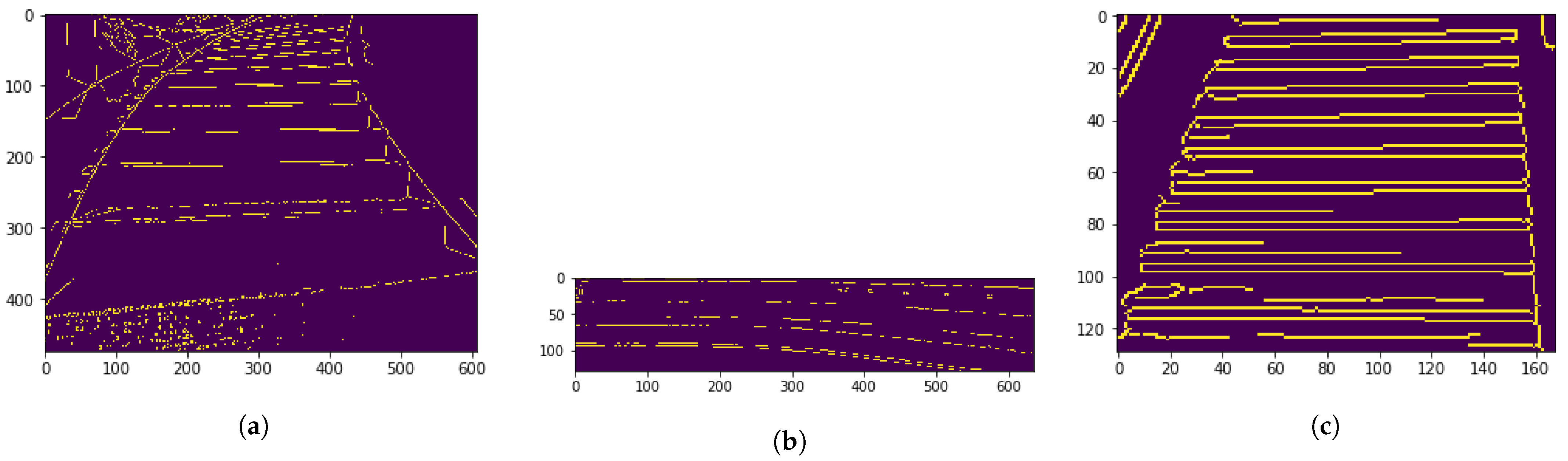
This section discusses results pertaining to the detection of the first step of staircases. We use width of the staircase as the to filter out small contours. Furthermore, we filter out all vertical edges by using a parameter of ≈60°. The algorithm is able to detect both the target point, , and the angle of approach, , with good accuracy. The accuracy in localizing the middle point of the first step of the staircase was achieved as ±2 cm, and the accuracy in finding the orientation of the middle point was ±1 degree, with respect to the true center point.
The results are shown in
Figure 8. Here, the first step of the staircase detected using contour detection is denoted by the line. The cross represents the computed target point,
. The detected angle of approach,
, is also shown below each figure. The algorithm is able to detect these with good accuracy, as shown in
Figure 8a–c,e,f.
Figure 8d is the image of a textured staircase, where the approach is not very consistent due to the noise generated during Canny edge detection.
The edges detected for this image are shown in
Figure 9a. Optimal edge detection results are shown in
Figure 9b,c.
5.3. Real-Time Performance
This section details the real-time tests performed using our proposed model. An image stream coming from the sTetro camera is used to determine the movement direction of the robot in real time. The first step of the detected staircase is extracted from the processed images in the server, which, ultimately, returns a direction logic (i.e., angle of approach) to the robot. The details of the target point (position and angle) are sent to the robot to move toward the target point. In this test, the robot moves from the left to the right of the staircase.
The detection of the staircase during this test is shown in
Figure 10a–e. The first step detection for these figures is shown in
Figure 10f–j. The directions predicted are accurate during our testing scenarios, with minor errors occurring on textured staircases. The target point is predicted accurately. However, for real-time applications, the running time of the algorithm is also crucial. This is given in
Table 3. The overall approach takes about 150 ms on average, which is feasible for real-time applications. The high computation times usually occur during the first run, which can be attributed to the loading of the model into memory.
The performance measure definitions are given in [
46], and the performance curves are plotted in
Figure 11.
In summary, the recall–precision curve is a valuable tool for assessing the performance of a binary classification model across different threshold values. It helps in making informed decisions about the balance between correctly identifying positive instances (recall) and ensuring their accuracy (precision), whereas the F1 score, which is the harmonic mean of precision and recall, is often used to find a balance between these two metrics. The threshold point (0.5) on the curve where the F1 score (0.87) is maximized represents a balanced trade-off between precision (0.75) and recall (0.52). A sample test video of an experiment is referred to in [
8].
In [
47], Prasanna et al. make use of heterogeneous robots with high-end perception sensor payloads. These kinds of robots are very costly and can be used for inspection tasks only. In [
48], Patil et al. use YOLOv3 and achieve an F1 Score of 0.81, as compared to our method with an F1 Score of 0.87. An RGBD camera is used in [
49] to localize the steps of a staircase. It is observed that the localization error of the center point increases as the distance from the staircase increases. This is due to the sensitivity of depth error with distance. Errors are >5 cm, as compared to ours, which are <2 cm errors.
6. Conclusions and Future Work
In this article, we presented a framework for real-time detection and localization of staircases with low-cost embedded systems by incorporating ROS middleware as a computational environment into indoor cleaning robots for use in multi-floor buildings. Low-cost object deep learning detection networks, such as MobileNet and SSD architectures, were used for real-time recognition of staircases in the incoming video stream. In this robotic application, it was crucial to determine the middle point and angle of approach of the first step of the staircase. This was achieved by utilizing the well-known Canny edge detection followed by our proposed contour detection algorithm. Through this algorithm, the robot was able to identify the point close to the center of the first step (target point) and the angle of approach to the target point, which, in turn, are used to determine the direction of movement of the robot. This algorithm aligns the robot to the staircase so that it can reach the middle of the first step and start traversing the staircase. We leveraged the transfer learning technique and trained and tested the proposed model using a custom dataset consisting of 11 images of different staircases captured from a sTetro robot fitted with an RGB camera at the top. Further, the model was tested against objects that have features similar to staircases. The model was able to differentiate between the staircase and non-staircase classes with an accuracy of 95% and determine the target point and the angle of approach to the first step of the staircase with an accuracy of ±2 cm, ±1 degree. We tested this model in real-time scenarios and found that it can be used in slow-moving platforms, like sTetro, which have limited computational resources onboard. This work had limitations in distinguishing among the different shapes and types of staircases, such as straight, curved, spiral, and L-shaped staircases. Currently, it can recognize between stairs and non-stair classes. In the future, this work can be extended to recognize the types of staircases as well. This would allow the robot to switch between movement operational modes according to the type of staircase encountered. Further work can be conducted to implement the classification and localization algorithms onboard the mobile robot.


