


Numerical Investigation on the Performance of Horizontal Helical-Coil-Type Backfill Heat Exchangers with Different Configurations in Mine Stopes


Abstract
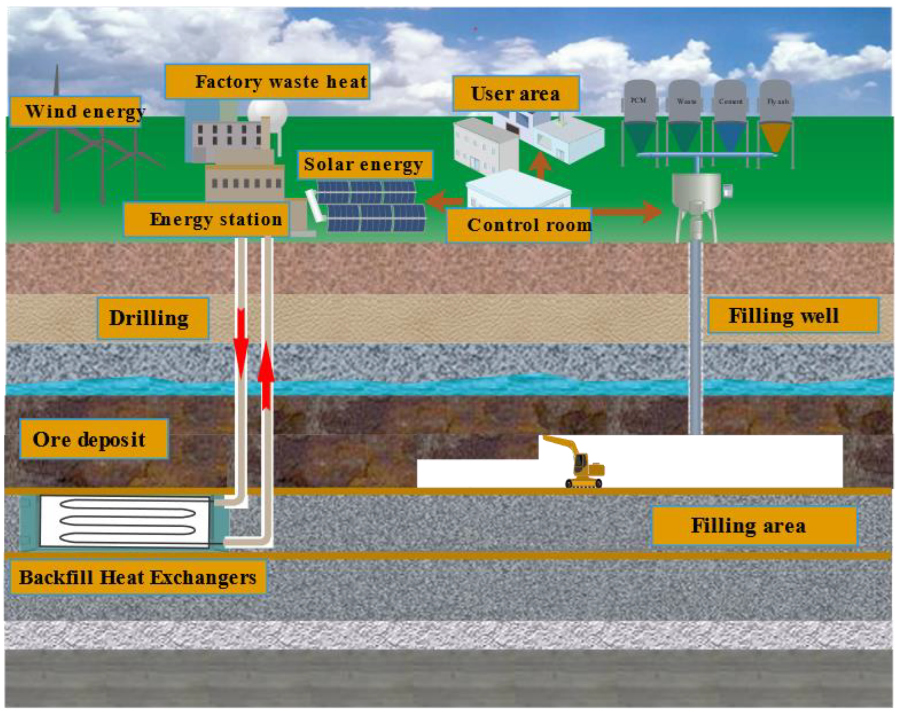
:1. Introduction
2. Numerical Modeling
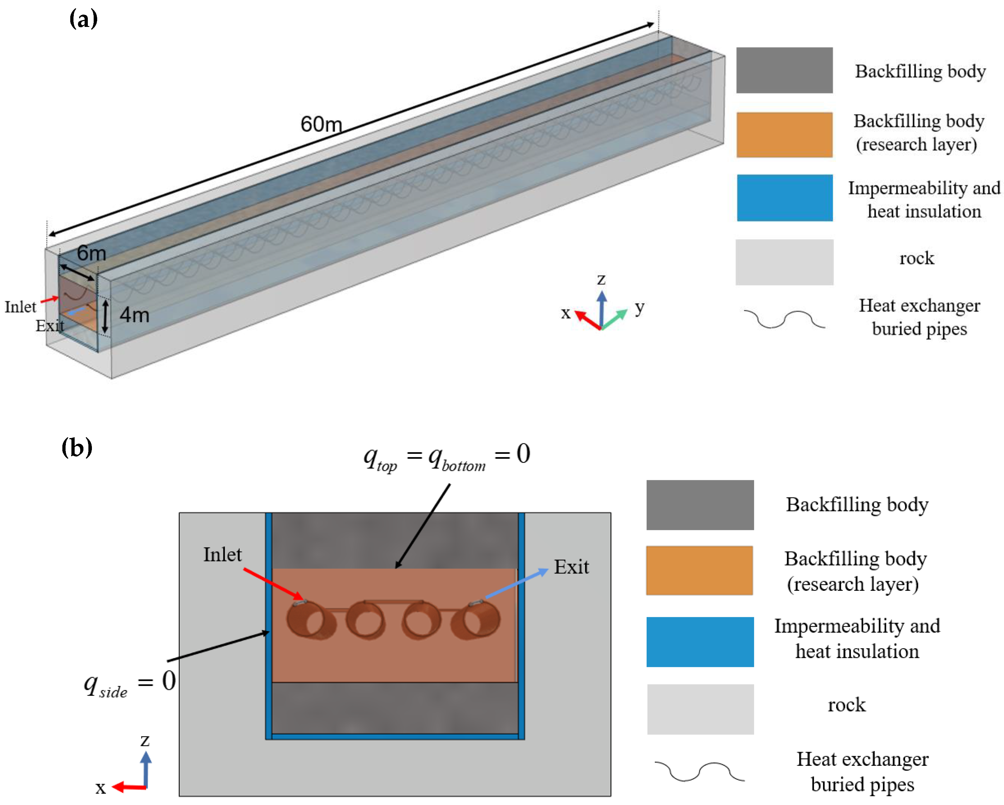
2.1. Physical Model
2.2. Mathematical Model
- (1)
- The backfilling body is homogeneous and isotropic;
- (2)
- Neglect the contact thermal resistance between the buried pipe wall and the backfilling body and the contact thermal resistance between the backfilling body and the surrounding rock;
- (3)
- The influence of underground seepage is not considered;
- (4)
- The heat transfer fluid is an incompressible fluid, and the temperature and velocity are uniform in any radial section;
- (5)
- The thermo-physical properties of materials are temperature-independent.
2.2.1. Governing Equation
- (1)
- Backfill body region
- (2)
- Backfill Heat Exchangers region
2.2.2. Boundary Condition
- (1)
- BFHEs are provided with impermeable and thermal insulation on both sides of the backfilling body (as shown in Figure 2), so both sides are set to be adiabatic in the simulation:
- (2)
- Based on geometric symmetry, the top and bottom of the backfilling of BFHEs are adiabatic surfaces:
- (3)
- Inlet temperature of heat exchanger buried pipe:where Tf,in is the temperature of the heat transfer fluid at the inlet of the heat transfer buried pipes, the heat storage phase is taken as 90 °C, and the heat release phase is taken as 20 °C [9].
- (4)
- Buried pipe inlet volume flow rate:
2.2.3. Initial Conditions
3. Numerical Simulation and Verification
3.1. Geometric Modeling and Meshing
3.2. Grid and Time-Step Independence Verification
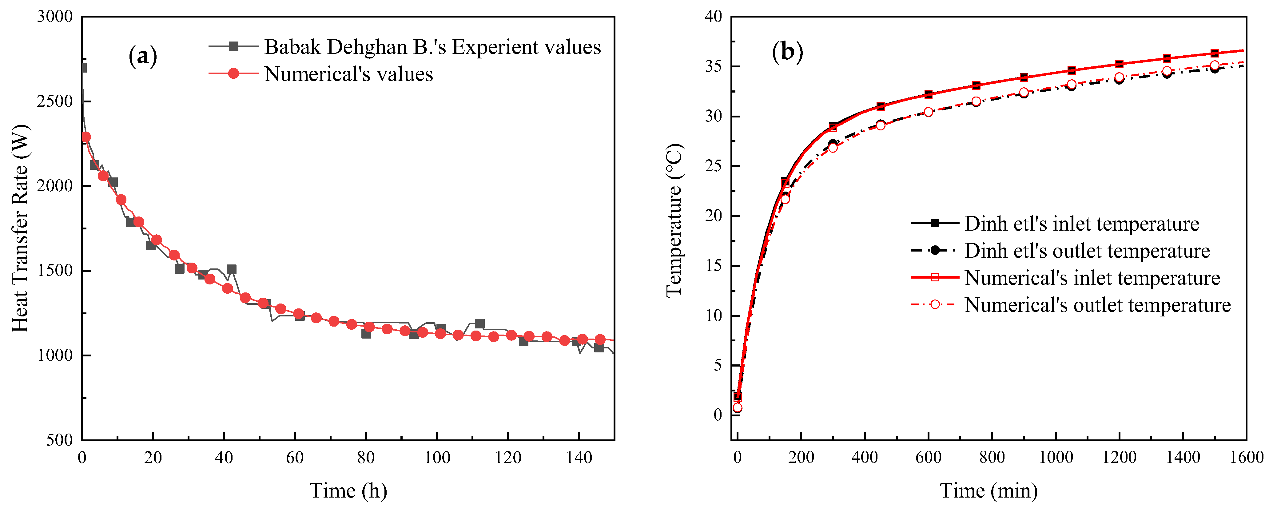
3.3. Model Validation
4. Evaluation Indicators
4.1. Accumulated Heat Storage/Release and Heat Storage/Release Rate
4.2. Total Heat Storage and Release Efficiency
4.3. Comprehensive Heat Transfer Performance
5. Simulation Results and Analysis
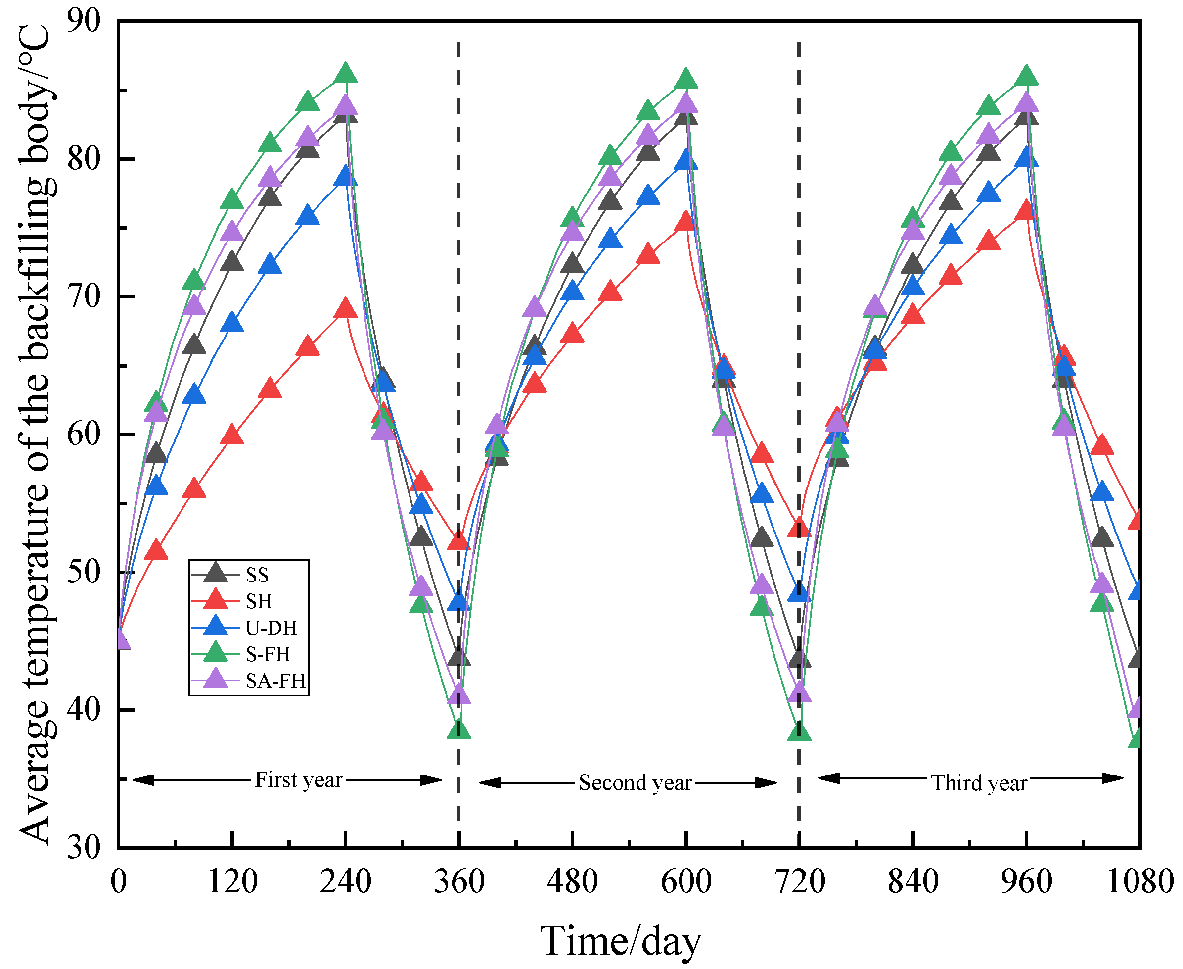
5.1. Comparative Analysis of the Heat Storage/Release Characteristics of BFHEs in Five Arrangement Forms
5.2. The Influence of Helix Pitch Length and Pitch Diameter
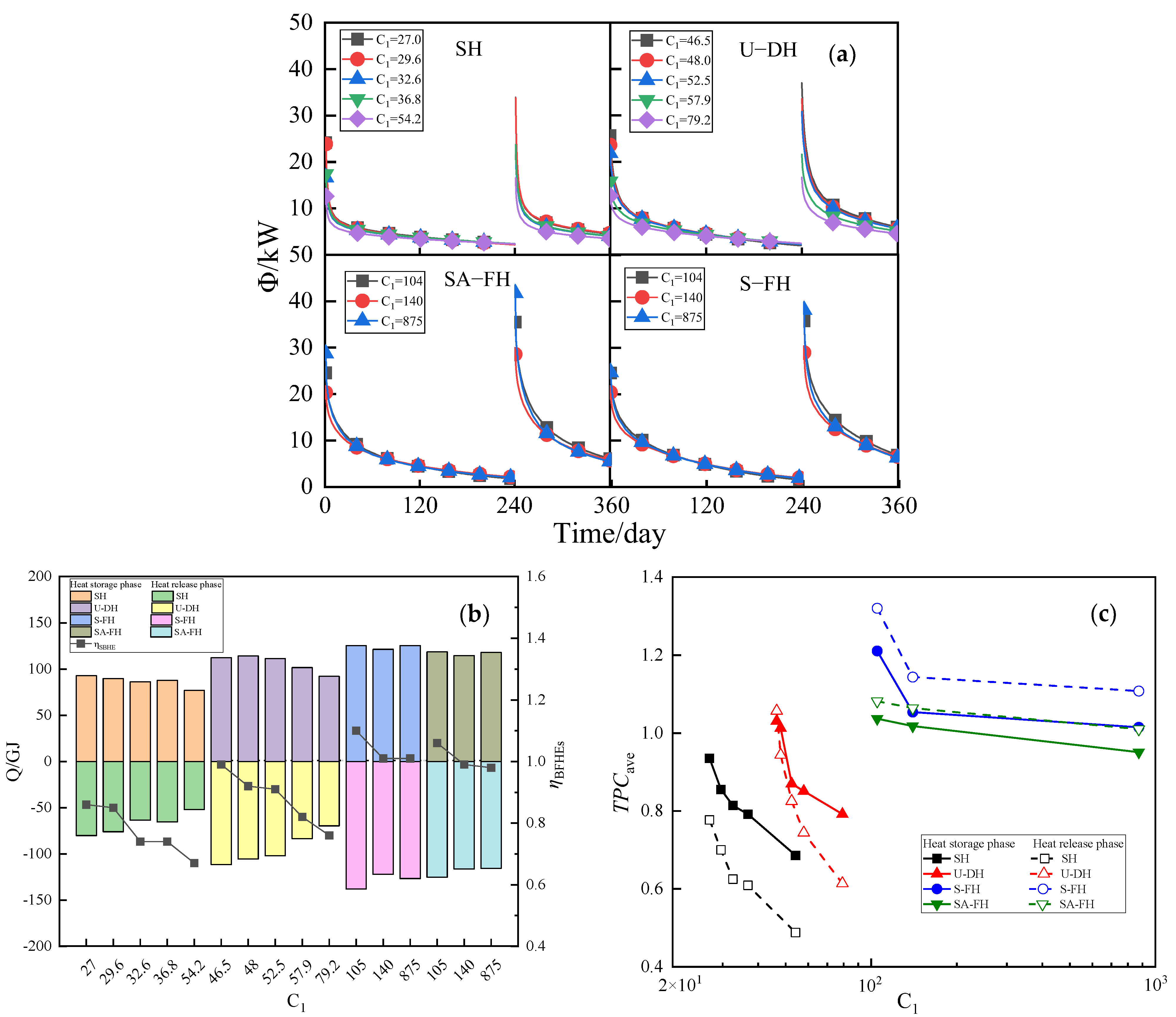
5.2.1. The Influence of Helix Pitch Length
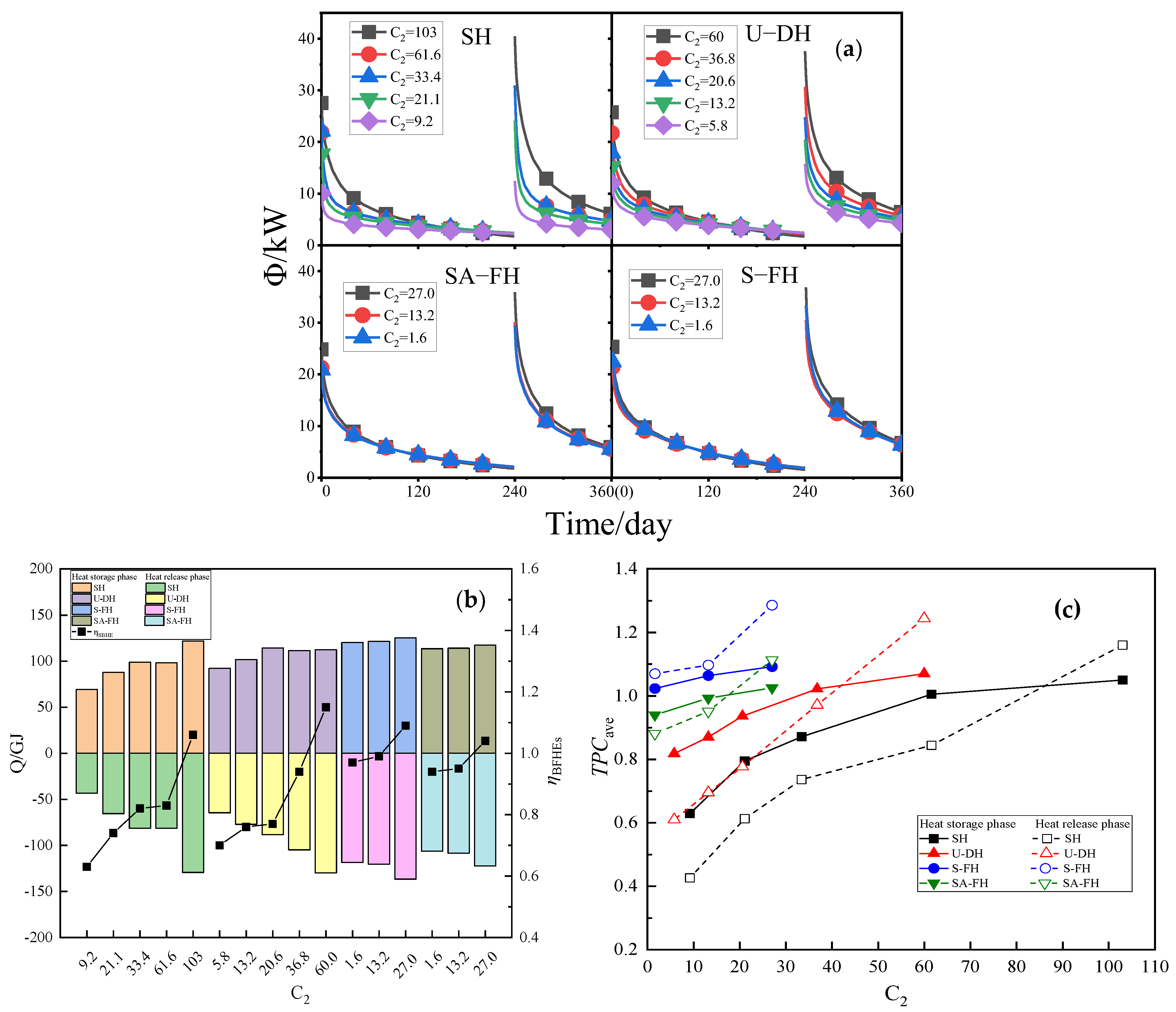
5.2.2. The Influence of Pitch Diameter
5.3. The Influence of Thermal Conductivity
6. Conclusions
- (1)
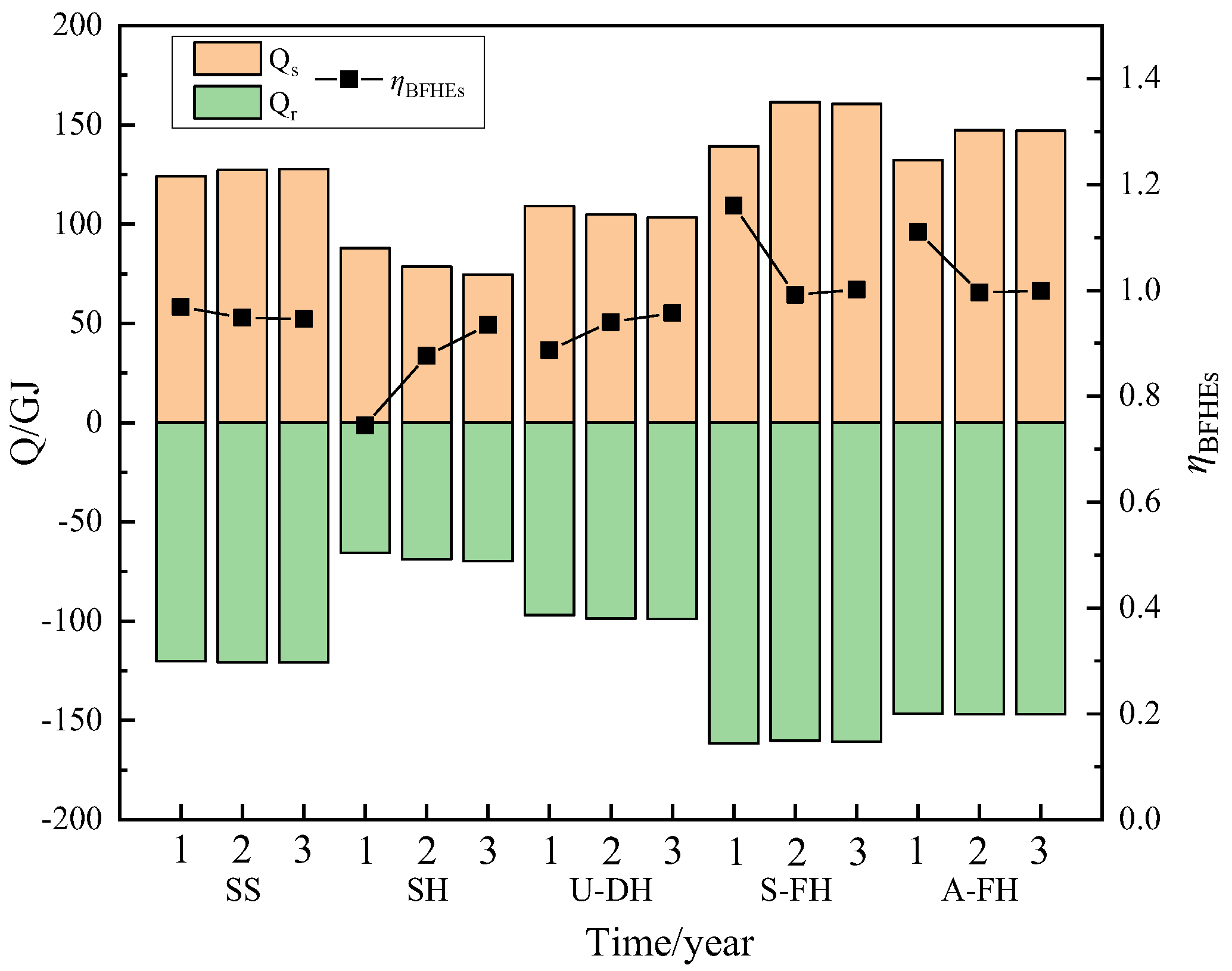
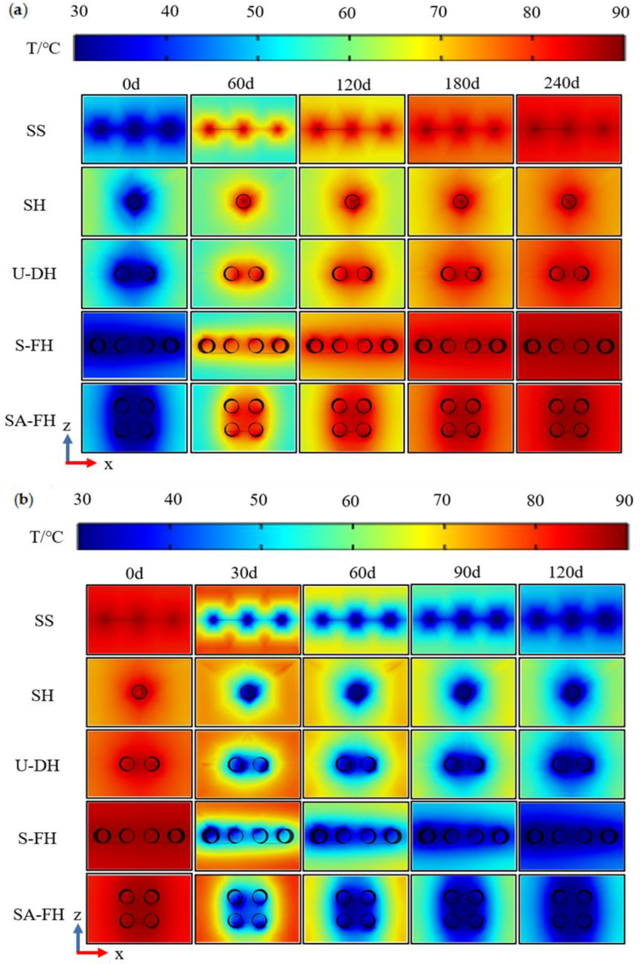
- Compared with the conventional Serpentine Straight-pipes (SS), the Serpentine-type four helix-pipes (S-FH) have the best fit with the internal heat transfer of the backfill body in the mining layer of the metal mine, and the internal temperature distribution of the backfill body is the most uniform throughout the processes of heat storage/release. And it can increase the capacity of heat storage/release of BFHEs by a large amount of 21.7%. The next best configuration, with an improvement of 11.1%, is the Square Array-type four helix-pipes (SA-FH). The Single Helix-pipes (SH) and U-type Double Helix-pipes (U-DH) layouts, which have fallen by 19.9% and 42.7%, respectively, are both subpar.
- (2)
- The pipe configuration significantly affects the change in the heat storage/release rate of BFHEs, especially in the early phase of the heat storage/release processes. With a maximum increase of roughly 15 kW, S-FH and SA-FH have much higher heat storage/release rates than SS, but U-DH and SH have significantly lower rates.
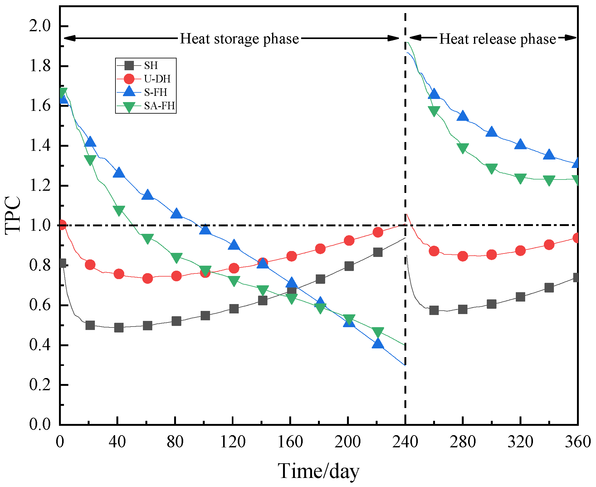
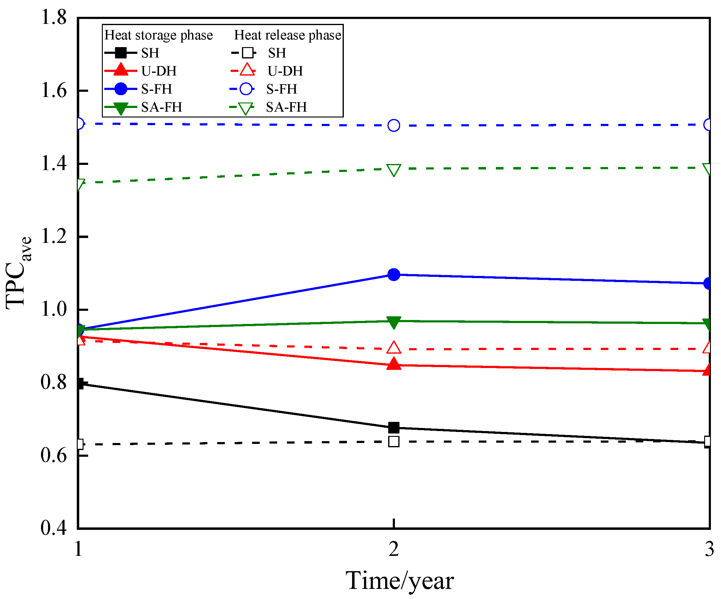
- (3)
- Given the flow resistance, the pipe configuration distinctly influences the thermal performance capability of helical BFHEs. When BFHEs are operating steadily, S-FH and SA-FH have TPCave in the heat storage phase that is similar to that of SS at roughly 1.10 and 0.96 and in the heat release phase that is substantially higher at 1.51 and 1.39. The TPCave of U-DH and SH, at roughly 0.85 and 0.64, respectively, is significantly lower than that of SS during the heat storage/release phase.
- (4)
- To enhance the thermal performance and heat storage/release capacity of helical BFHEs, it is advantageous to decrease the pitch length to pipe diameter ratio (C1) and increase the pitch diameter to pipe diameter ratio (C2).
- (5)
- The thermal performance of helical BFHEs can be effectively improved by increasing the backfill body’s thermal conductivity, with SH experiencing the greatest improvement and S-FH experiencing the least improvement. The average increases in the heat storage/release rates of SH, U-DH, SA-FH, and S-FH are 46%/78%, 34%/67%, 25%/40%, and 22%/39%, respectively, when the thermal conductivity is raised from 0.4 W/(m·k) to 0.8 W/(m·k).
Author Contributions
Funding
Data Availability Statement
Conflicts of Interest
Nomenclature
| Symbols | ||
| Ap | cross-section area of pipe (m2) | |
| cp | specific thermal capacity (kJ/(kg·K)) | |
| dh | buried pipe diameter (m) | |
| Dh | pitch diameter (m) | |
| f | friction coefficient | |
| fD | Darcy friction factor | |
| hext | outer wall of the heat transfer coefficient (W/(m2·k)) | |
| Hh | helix height (m) | |
| hint | inlet wall of the heat transfer coefficient (W/(m2·k)) | |
| LT | total length of the heat transfer buried pipe (m) | |
| m | the mass flow rate of heat transfer fluid (kg/s) | |
| p | head pressure inside the pipe (Pa) | |
| Ph | pitch length (m) | |
| ∆P | pressure drop of the heat transfer buried pipe (Pa) | |
| Q | cumulative heat storage/release of BFHEs (kJ) | |
| Qf,in | Volume flow rate of the heat transfer fluid (m3/s) | |
| Qr | total heat exchange in heat release phase (kJ) | |
| Qs | total heat exchange in heat storage phase (kJ) | |
| Qwall | heat flow through the wall of the heat exchanger pipe (W/m) | |
| r0 | inner radius of the heat exchanger buried pipes [m] | |
| ri | outer radius of the heat exchanger buried pipes [m] | |
| T | Temperature (°C) | |
| T0 | initial temperature of BFHEs in the heat storage phase (°C) | |
| Te | initial temperature of BFHEs in the heat release phase (°C) | |
| Tf,in | inlet temperature of the heat transfer fluid (°C) | |
| Greek Letters | ||
| ρ | Density (kg/m3) | |
| ϑ | flow rate of heat transfer fluid (m/s) | |
| υ | kinematic viscosity (m2/s) | |
| Φ | storage/release of heat rate of BFHEs (kW) | |
| η | ratio of the effective cumulative heat release to the heat storage | |
| ∇ | the gradient: | |
| Subscripts | ||
| τ | time (s) | |
| b | backfilling body | |
| p | heat transfer buried pipes | |
| f | heat transfer fluid | |
| Abbreviations | ||
| BFHEs | Backfill heat exchangers | |
| TPC | Thermal performance coefficient | |
References
- Rasih, R.A.; Sidik, N.A.C.; Samion, S. Recent progress on concentrating direct absorption solar collector using nanofluids. J. Therm. Anal. Calorim. 2019, 137, 903–922. [Google Scholar] [CrossRef]
- Memme, S.; Boccalatte, A.; Brignone, M. Simulation and design of a large thermal storage system: Real data analysis of a smart polygeneration micro grid system. Appl. Therm. Eng. 2022, 201, 117789. [Google Scholar] [CrossRef]
- Li, G.; Li, M.; Taylor, R. Solar energy utilisation: Current status and roll-out potential. Appl. Therm. Eng. 2022, 209, 118285. [Google Scholar] [CrossRef]
- Cai, X.; Yuan, J.; Zhou, Z.; Pi, Z.; Tan, L.; Wang, P.; Wang, S.; Wang, S. Effects of hole shape on mechanical behavior and fracturing mechanism of rock: Implications for instability of underground openings. Tunn. Undergr. Space Technol. 2023, 141, 105361. [Google Scholar] [CrossRef]
- Zhou, Z.; Wang, P.; Cai, X.; Cao, W. Influence of Water Content on Energy Partition and Release in Rock Failure: Implications for Water-Weakening on Rock-burst Proneness. Rock Mech. Rock Eng. 2023, 56, 6189–6205. [Google Scholar] [CrossRef]
- Zhou, Z.; Cai, X.; Li, X.; Cao, W.; Du, X. Dynamic Response and Energy Evolution of Sandstone Under Coupled Static–Dynamic Compression: Insights from Experimental Study into Deep Rock Engineering Applications. Rock Mech. Rock Eng. 2020, 53, 1305–1331. [Google Scholar] [CrossRef]
- Ghoreishi-Madiseh, S.A.; Hassani, F.; Abbasy, F. Numerical and experimental study of geothermal heat extraction from backfilled mine stopes. Appl. Therm. Eng. 2015, 90, 1119–1130. [Google Scholar] [CrossRef]
- Guo, P.; Wang, M.; Sun, X.; He, M. Study on off-season cyclic energy storage in underground space of abandoned mine. J. China Coal Soc. 2022, 47, 2193–2206. [Google Scholar] [CrossRef]
- Li, B.; Zhang, J.; Ghoreishi-Madiseh, S.A.; de Brito, M.A.R.; Deng, X.; Kuyuk, A.F. Energy performance of seasonal thermal energy storage in underground backfilled stopes of coal mines. J. Clean. Prod. 2020, 275, 122647. [Google Scholar] [CrossRef]
- Zhang, B.; Xue, P.; Liu, L.; Huan, C.; Wang, M.; Zhao, Y.; Qin, X.; Yang, Q. Exploration on the method of ore deposit-geothermal energy synergetic mining in deep backfill mine. J. China Coal Soc. 2021, 46, 2824–2837. [Google Scholar] [CrossRef]
- Zhao, Y.; Liu, L.; Wen, D.; Zhang, B.; Zhang, X.; Huan, C.; Wang, M.; Wang, X. Experimental study of horizontal ground heat exchangers embedded in the backfilled mine stopes. Geothermics 2022, 100, 102344. [Google Scholar] [CrossRef]
- Sivasakthivel, T.; Philippe, M.; Murugesan, K. Experimental thermal performance analysis of ground heat exchangers for space heating and cooling applications. Renew. Energ. 2017, 113, 1168–1181. [Google Scholar] [CrossRef]
- Pu, L.; Xu, L.; Qi, D.; Li, Y. Structure optimization for horizontal ground heat exchanger. Appl. Therm. Eng. 2018, 136, 131–140. [Google Scholar] [CrossRef]
- Larwa, B.; Teper, M.; Grzywacz, R.; Kupiec, K. Study of a slinky-coil ground heat exchanger—Comparison of experimental and analytical solution. Int. J. Heat Mass Transf. 2019, 142, 118438. [Google Scholar] [CrossRef]
- Yoon, S.; Lee, S.R.; Go, G.H. Evaluation of thermal efficiency in different types of horizontal ground heat exchangers. Energy Build. 2015, 105, 100–105. [Google Scholar] [CrossRef]
- Zhao, Q.; Chen, B.; Liu, F. Study on the thermal performance of several types of energy pile ground heat exchangers: U-shaped, W-shaped and helix-shaped. Energy Build. 2016, 133, 335–344. [Google Scholar] [CrossRef]
- Saeidi, R.; Noorollahi, Y.; Esfahanian, V. Numerical simulation of a novel helix type ground heat exchanger for enhancing heat transfer performance of geothermal heat pump. Energy Convers. Manag. 2018, 168, 296–307. [Google Scholar] [CrossRef]
- Kim, M.J.; Lee, S.R.; Yoon, S.; Go, G.H. Thermal performance evaluation and parametric study of a horizontal ground heat exchanger. Geothermics 2016, 60, 134–143. [Google Scholar] [CrossRef]
- Javadi, H.; Ajarostaghi, S.S.M.; Pourfallah, M.; Zaboli, M. Performance analysis of helical ground heat exchangers with different configurations. Appl. Therm. Eng. 2019, 154, 24–36. [Google Scholar] [CrossRef]
- Serageldin, A.A.; Radwan, A.; Katsura, T.; Sakata, Y.; Nagasaka, S.; Nagano, K. Parametric analysis, response surface, sensitivity analysis, and optimization of a novel helix-double ground heat exchanger. Energy Convers. Manag. 2021, 240, 114251. [Google Scholar] [CrossRef]
- Jalaluddin; Miyara, A. Thermal performance and pressure drop of helix-pipe ground heat exchangers for ground-source heat pump. Appl. Therm. Eng. 2015, 90, 630–637. [Google Scholar] [CrossRef]
- Shi, Y.; Cui, Q.; Song, X.; Xu, F.; Song, G. Study on thermal performances of a horizontal ground heat exchanger geothermal system with different configurations and arrangements. Renew. Energ. 2022, 193, 448–463. [Google Scholar] [CrossRef]
- Dinh, B.H.; Kim, Y.S.; Yoon, S. Experimental and numerical studies on the performance of horizontal U-type and helix-coil-type ground heat exchangers considering economic aspects. Renew. Energ. 2022, 186, 505–516. [Google Scholar] [CrossRef]
- Rashidi, S.; Bakhshi, N.; Rafee, R. Progress and challenges of helical-shaped geothermal heat exchangers. Environ. Sci. Pollut. Res. 2021, 28, 28965–28992. [Google Scholar] [CrossRef] [PubMed]
- Lu, X.; Wang, W.; Zou, L.; Kou, Y. Parameters Optimizaion of Stoping Drift Under Massive Backfill Based on Combined Weighting. Min. Res. Dev. 2022, 42, 15–21. [Google Scholar] [CrossRef]
- Park, S.; Sung, C.; Jung, K.; Sohn, B.; Chauchois, A.; Choi, H. Constructability and heat exchange efficiency of large diameter cast-in-place energy piles with various configurations of heat exchange pipe. Appl. Therm. Eng. 2015, 90, 1061–1071. [Google Scholar] [CrossRef]
- Liang, B.; Chen, M.; Fu, B.A.; Guan, J. Thermal and flow characteristics in a vertical helix-type ground heat exchanger based on linear non-equilibrium thermodynamic principle. Energy Build. 2022, 266, 112111. [Google Scholar] [CrossRef]
- Zhang, H.; Yu, Y.; Hu, C. Selection of pipe diameter for ground-source heat pump system. J. Heat. Vent. Air Cond. 2012, 42, 114–117. [Google Scholar]
- Zhang, X.; Xu, M.; Liu, L.; Huan, C.; Zhao, Y.; Qi, C.; Song, K.I. Experimental study on thermal and mechanical properties of cemented paste backfill with phase change material. J. Clean. Prod. 2020, 9, 2164–2175. [Google Scholar] [CrossRef]
- Zhang, B.; Yang, Z.; Liu, L.; Zhao, Y.; Huan, C.; Wang, M.; Tu, B. Study on the thermal interference of backfill heat exchangers in heat storage/release processes in deep mines. J. China Coal Soc. 2023, 48, 1155–1168. [Google Scholar] [CrossRef]
- Li, C.; Cleall, P.J.; Mao, J.; Muñoz-C, J.J. Numerical simulation of ground source heat pump systems considering unsaturated soil properties and groundwater flow. Appl. Therm. Eng. 2018, 139, 307–316. [Google Scholar] [CrossRef]
- Wu, L.; Kang, T.; Yin, B.; Du, M. Microcalorimetric test and analysis of hydration heat of fly ash paste-filling material. J. China Coal Soc. 2015, 40, 2801–2806. [Google Scholar] [CrossRef]
- Gan, D.; Sun, H.; Xue, Z.; Yan, Z.; Liu, Z. Flow Characteristics of Slurry Conveying Pipe with Large Flow under High Temperature Environment. Met. Mine 2021, 539, 43–49. [Google Scholar] [CrossRef]
- Dehghan, B.B. Experimental and computational investigation of the helix ground heat exchangers for ground source heat pump applications. Appl. Therm. Eng. 2017, 121, 908–921. [Google Scholar] [CrossRef]
- Zhang, H.; Hou, H.; Han, J.; Zhang, Q.; Jin, T. Simulation and Analysis of Performance of Seasonal Borehole Thermal Energy Storage. J. Eng. Thermophys. 2022, 43, 1148–1154. [Google Scholar]
- Yang, W.; Xu, R.; Wang, F.; Chen, S. Experimental and numerical investigations on the thermal performance of a horizontal helix-coil ground heat exchanger. J. Eng. Thermophys. 2022, 147, 979–995. [Google Scholar] [CrossRef]


| Pipe Distribution Form | Pipe Inner Diameter /m | Pipe Length /m | Total Surface Area of Pipe Inner Wall /m2 | Pitch Diameter /m | Helix Pitch /m |
|---|---|---|---|---|---|
| SH | 0.038 | 183.7 | 21.75 | 0.8 | 1.4 |
| U-DH | 0.028 | 248.0 | 21.80 | ||
| S-FH/SA-FH | 0.016 | 433.4 | 21.77 | ||
| SS * | 0.038 | 182.3 | 21.75 | / | |
| Material | Density (m3/kg) | Thermal Conductivity W/(m·K) | Specific Heat Capacity J/(kg·K) |
|---|---|---|---|
| Backfill body | 1709 | 0.6 | 1235 |
| Copper | 8500 | 110 | 393.6 |
| Rock | 2400 | 2.5 | 2000 |
| Type | Parameter | Value |
|---|---|---|
| Heat transfer fluid (water) | Qf,in (inlet volume flow rate) | 3.5 × 10⁻⁴ m3/s |
| ρ (density of water) | 998 m3/kg | |
| λ (thermal conductivity of water) | 0.6 W/(m·k) | |
| cp (specific heat of water) | 4182 J/(kg·K) |
| Model | Dinh B.H. | Dehghan B.B. | |
|---|---|---|---|
| Geometric dimensions of models | 5 × 1 × 1 m | 6 × 6 × 4 m | |
| Backfill materials | Density | 1782 m3/kg | 2100 m3/kg |
| Thermal conductivity | 1.62 W/(m·k) | 1.8 W/(m·k) | |
| Specific heat | 860 J/(kg·K) | 900 J/(kg·K) | |
| Heat transfer fluid (water) | Volume flow rate | 4 L/min | 15 L/min |
| Inlet temperature | change over time | 50 °C | |
| Operation time | 1600 min | 150 h | |
Disclaimer/Publisher’s Note: The statements, opinions and data contained in all publications are solely those of the individual author(s) and contributor(s) and not of MDPI and/or the editor(s). MDPI and/or the editor(s) disclaim responsibility for any injury to people or property resulting from any ideas, methods, instructions or products referred to in the content. |
© 2023 by the authors. Licensee MDPI, Basel, Switzerland. This article is an open access article distributed under the terms and conditions of the Creative Commons Attribution (CC BY) license (https://creativecommons.org/licenses/by/4.0/).
Share and Cite
Zhang, B.; Shi, L.; Zhang, W.; Huan, C.; Zhao, Y.; Wang, J. Numerical Investigation on the Performance of Horizontal Helical-Coil-Type Backfill Heat Exchangers with Different Configurations in Mine Stopes. Mathematics 2023, 11, 4173. https://doi.org/10.3390/math11194173
Zhang B, Shi L, Zhang W, Huan C, Zhao Y, Wang J. Numerical Investigation on the Performance of Horizontal Helical-Coil-Type Backfill Heat Exchangers with Different Configurations in Mine Stopes. Mathematics. 2023; 11(19):4173. https://doi.org/10.3390/math11194173
Chicago/Turabian StyleZhang, Bo, Long Shi, Wenxuan Zhang, Chao Huan, Yujiao Zhao, and Jingyu Wang. 2023. "Numerical Investigation on the Performance of Horizontal Helical-Coil-Type Backfill Heat Exchangers with Different Configurations in Mine Stopes" Mathematics 11, no. 19: 4173. https://doi.org/10.3390/math11194173
APA StyleZhang, B., Shi, L., Zhang, W., Huan, C., Zhao, Y., & Wang, J. (2023). Numerical Investigation on the Performance of Horizontal Helical-Coil-Type Backfill Heat Exchangers with Different Configurations in Mine Stopes. Mathematics, 11(19), 4173. https://doi.org/10.3390/math11194173