Abstract
In this paper, a fixed-switching-frequency modulated model predictive control (MPC) is established for a two-level three-phase voltage source inverter (VSI) working in an islanded AC microgrid. These small-scale power systems are composed by two or more VSIs which interface DGs, controlling the voltage amplitude and frequency in the system, and simultaneously sharing the load active and reactive power. Generally, these operational characteristics are achieved using hierarchical linear control loops, but with challenging limitations such as slow transient reaction to disturbances and high proneness to be affected by parameter modifications. Model predictive control may solve these issues. Nevertheless, the most used and developed predictive control scheme, the finite-set model predictive control (FS-MPC), presents the drawback of having the harmonic spectrum spread over all the frequencies. This brings issues with coupling between the different hierarchical control levels of the whole microgrid system, and eventually, when designing the filters for main-grid connection. This paper aims to solve these issues by developing the fixed-switching-frequency MPC working with higher-level control loops for operation in an islanded AC microgrid. These advantages are proved in an AC microgrid configuration where methodology for paralleling multiple MPC-regulated VSIs is described, with rapid transient response, inherent stability, and fully decentralised operation of individual VSIs, achieving proper load power sharing, eliminating circular currents, and proper waveforms for output currents and capacitor voltages. All these achievements have been confirmed via simulation and experimental verification.
Keywords:
AC microgrid; fixed-switching-frequency modulated model predictive control; voltage source inverter; power sharing; droop control MSC:
93C95
1. Introduction
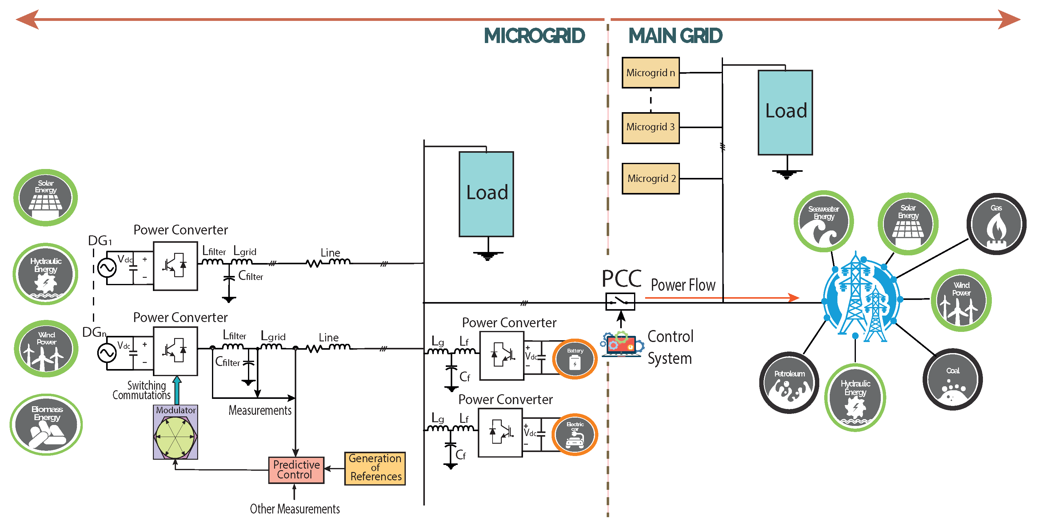
As part of the emerging clean energy technologies for decarbonising the energy systems, microgrids play a paramount role as they are compatible with renewable energy sources, especially in territories with high availability of these energy sources [1]. A common configuration of an AC microgrid with its control system can be seen in Figure 1. This new type of power system provides improved reliability and flexibility compared to individual energy sources by bringing together multiple distributed generators (DGs) [2]. A key feature of microgrids is their capacity of operating in both grid-connected and islanded modes [3,4]. For stable and economically feasible operation, a microgrid in an islanded mode must have the active and reactive powers of the DGs proportionally shared by their respective power ratings [5].
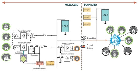
Figure 1.
Diagram of a power converter-interfaced microgrid with DGs, with decentralised control for power converters and a central controller at the PCC interfacing the main grid.
The way to exert proportional power sharing without any external communication is by utilising droop control between the VSIs embedded in the microgrid system [6].
Microgrids, under grid-connected operation, can exchange energy with the main grid. Consequently, the microgrid takes the voltage and frequency references from the main grid [7]. On the other hand, a microgrid operating in islanded mode is not influenced by the main grid. For referencing its voltage and frequency levels, islanded microgrids use VSI-interfaced DG units [8]. Consequently, power sharing between the DG units may be hampered by several issues, e.g., dissimilarities in line impedances, unequal voltage levels, and local loads, among others [7].
In microgrids with paralleled power converters, the appearance of circulating currents has become a potentially damaging issue to deal with, even leading to overloaded inverters, reductions in power quality, growth of losses and impacts on system efficiency [9]. The reason behind the appearance of these circulating currents is due to discords in voltages, line impedances or among phases [10]. Circulating currents are not a significant problem in traditional power systems, due to the fact that transmission lines in main grids are capable of reducing these currents, whereas microgrids have smaller impedances that prevent elimination of circulating currents from the system [7].
Given the relevance of circulating currents is demonstrated by the fact that most control schemes developed are aimed at solving them, using power sharing between inverters, and taking into consideration mismatches in the line impedances in the microgrid [11]. The nature of the circulating currents can be both active and reactive and are due to mismatches between the output voltages of the VSIs. The damaging effect over the system is also dependent on the microgrid´s R/X ratio. A technique that can be used together with droop control is the virtual impedance method [7]. Their combination is able to deliver satisfactory power sharing results and represents a highly feasible tool for decentralised control of microgrids [12], though it may lead to an increase in harmonic disturbances in the output waveforms of the system [13].
This power sharing control among the several DGs in a microgrid is referred to as primary control or outer-loop in a decentralised and hierarchical control-based microgrid’s architecture. Additionally, there is the inner-loop voltage–current feedback control that operates in the VSI interfacing each of the DGs in the microgrid [9,14].
Nevertheless, when using cascade linear control, the effectiveness of droop control may worsen, with slow dynamics for dealing with disturbances and sudden step-changes, and adding harmonics content at low frequencies [7]. This is where the MPC scheme appears as a feasible and improved solution due to its fast transient features that allow it to operate under microgrid environments [1,3], even appearing as a very feasible and attractive solution for DC microgrids [15].
The advantage of using MPC lays on its nature and mathematical architecture: the utilisation of the system model to be controlled, in this case, the VSI [16]. For this, future behaviour of the VSI can be predicted and the optimal switching state of the power converter can also be obtained in agreement to a specifically designed cost function [1,16].
On the other side, FS-MPC employs the former mentioned control scheme, presenting a stimulating approach owing to its benefits such as fast dynamic response, straightforward incorporation of nonlinearities and constraints, and the possibility of including several control objectives utilising a single control loop, among others [17]. Nevertheless, FS-MPC has a well-known disadvantage: the variable switching frequency obtained at the converter output, affects the design of the required power filters to properly connect with the main grid [17] or for working in a grid-connected microgrid.
To deal with the problems associated with having variable switching frequency at the converter output, several strategies have been proposed to keep it fixed; obtaining the fundamental frequency at the output of the FS-MPC algorithm by using a low-pass filter and then synthesising using a modulator [18]; a digital bandstop filter is introduced in the cost function for shaping the frequency spectrum of the currents [19]. However, the damaging influence on the dynamic realisation of the FS-MPC algorithm, renders it inappropriate for high-performance applications [17]. Alternatively, for obtaining the converter voltage reference, a dead-beat predictive controller is used, and the commutation signals are obtained utilising space vector modulation (SVM) for a two-level grid-connected converter; thus, fixed-switching-frequency can be achieved [20].
Another path for producing fixed-switching-frequency, utilising an SVM algorithm to synthesise waveforms at the power converter output corresponds to a modified FS-MPC developed in [21]. Therein, this control scheme is a denominated modulated model-predictive control (MPC) and can function under fixed-switching-frequency mode with the same advantages that mainstream FS-MPC offers. In [22], an MPC strategy is used to control a multilevel solid-state transformer based on cascaded H-bridge power converter topology, using a multiobjective weighted-total-cost function for the current and the DC-link voltage. Furthermore, MPC is investigated in [17], where it is applied to control a three-level neutral-point-clamped (NPC) inverter, using a multiobjective cost function to concurrently control the current that is injected into the grid and to carry out the equilibrium of the DC-link capacitor voltages, using weighting factors in the cost function. Moreover, the authors in [17] investigate the use of a single-objective cost function to avoid the drawback that may consider adjusting the weighting factors, controlling the current and using redundant vectors to stabilise the DC-link capacitor voltages. In [23], a fast and fixed-switching-frequency MPC was investigated. By comparing the performance of traditional FS-MPC with the two fixed-switching-frequency MPC algorithms as proposed by the authors, the results show that the two last ones revealed that the harmonics spectrum is mainly focused around the switching frequency and its multiple switching frequencies. Their obtained results show that the switching frequencies cause harmonics spectrum with behaviour similar to the traditional space vector PWM (SVPWM) method and favourable to filter design. As expected, traditional FS-MPC showed that the current harmonics spectrum is distributed over different frequencies.
A different approach to fix the harmonics spectrum of a given frequency and its multiples is developed in [24], whereby to the MPC algorithm, in its cost function, some factors were added to achieve behaviour similar to that of a modulator, tracking a switching frequency reference: notch control (resonant filter [8]), periodic control, etc. These frequency control algorithms are added to the FS-MPC algorithm. These findings were not evaluated in a microgrid system.
Throughout the years, MPC has continued receiving significant attention among researchers as applications to grid-connected power converters has risen as a very important aspect [9,25]. For instance, in [26] a modified MPC was developed to improve performance with an optimisation near the hexagonal limit of voltage vectors and sector limits. This approach was not proved for islanded AC microgrids. As mentioned before, research on -filtered and grid-connected power converters is very close to microgrids research. In this way, the authors in [27] developed a fixed-switching-frequency MPC with continuous and discontinuous modulation for grid-tied converters with filters. A very interesting issue, and perhaps one of the main drivers to further advance the research in MPC, is that conventional FS-MPC will not fulfil grid codes for controlling grid-connected converters. This refers to the maximum current harmonics at the PCC with the main grid being 4.0% [9]. Thus, the work in [27] accomplishes this with those grid codes. Another interesting trend noted to achieve the advantages of both the fixed-switching-frequency and the MPC, is the utilisation of artificial neural networks (ANN) to optimally define the duty cycles of the active vectors, improving the results for the harmonics spectrum but with an increase in computational burden compared to MPC [28].
Referring to the employment of FS-MPC and MPC in the coordinated control of paralleled power converters in microgrids, it remains a field still in its infancy [1] and rarely reported in the coordinated control of multiple converters in microgrids [29]. Research on predictive control applied to paralleled inverters can be mentioned as in [30], where a multiple-input–multiple-output (MIMO) state-space model is developed, obtaining well-suited operation on both voltage-reference tracking and current sharing objectives. Nevertheless, the predictive controller is developed as a central controller, disallowing independent operation of the inverters. In another publication [31], the MPC scheme has been developed with an external-communication-based centralised control system for coordinating parallel operation of different VSIs interfacing DGs within a microgrid. Although centralised control may have proper operational ratings, it is bound to the availability of a dedicated communication system, leading to higher costs for microgrid system implementation [32]. In [29], a model predictive power control scheme and a model predictive voltage control are developed, to control buck-boost converters that interface the battery energy storage systems, and to control, combined with a direct droop control, the parallel inverters that interface the renewable energy sources, respectively. In that investigation, cost function is utilised to realise multiple control objectives and to select the optimal switching state. Nevertheless, the authors in [29] did not analyse the harmonics components in the obtained waveforms. In [33], an FS-MPC strategy is applied to standalone AC microgrids with two paralleled two-level three-phase voltage source converters, adding a cost function that simultaneously keeps track of several control objectives such as voltage regulation in the capacitor of the filter, implements a current restriction, penalises the switching effort, and adds a term for better tracking of the derivative of the capacitor voltage. This strategy proves to operate fully decentralised and each VSI is able to do it completely independent. Nevertheless, drawbacks of using FS-MPC are kept considering the harmonics spectrum, referring to its spread throughout the whole frequency range.
To deal with operation of paralleled-VSIs, delivering proper current and voltages, in terms of harmonics spectrum, this article presents a fixed-switching-frequency modulated model predictive control (MPC) strategy applied to two-level three-phase VSI operating in an isolated AC microgrid. Droop control with virtual resistance is used to generate the reference voltage for the inner-loop and to realise load-power sharing among two VSIs operating in parallel in the islanded AC microgrid. The fixed-switching-frequency predictive control applied in this work can achieve steady-state performance while its transient response is significantly improved. Proper load-power sharing and elimination of circulating currents are achieved by using this MPC strategy for a two-level three-phase VSI in an islanded AC microgrid. The main contributions of this paper to the field are:
- Application of the fixed-switching-frequency MPC scheme to a VSI into a decentralised and hierarchically controlled AC microgrid, fixing harmonics spectrum to a single frequency, while keeping fast transient response and stability in the microgrid system.
- Implementation of an MPC algorithm with a multivariable cost function to enhance the injected output current and the voltage in the islanded AC microgrid system.
The rest of the paper is organised as follows. In Section 2, the system of the VSI and the filters are described, with their respective mathematical models. Section 3 presents the fixed-switching-frequency MPC with a detailed description of this control strategy established as the inner-controller of the VSI with the filters. In Section 4, the primary control of the islanded AC microgrid system is discussed, along with several associated considerations and limitations. The methodology of building the AC microgrid from paralleled VSIs using fixed-switching-frequency MPC is also described in Section 4. Simulations results are given in Section 5. The experimental results are provided in Section 6. Simulation and experimental results are then discussed in Section 7, and finally, concluding remarks are given in Section 8 in addition to summary tables of the state-of-the-art developments on fixed-switching-frequency modulated model predictive control and microgrid applications.
2. System Description
In this section, the VSI and the filter are described, together with their respective mathematical models.
2.1. Two-Level Three-Phase Voltage Source Inverter
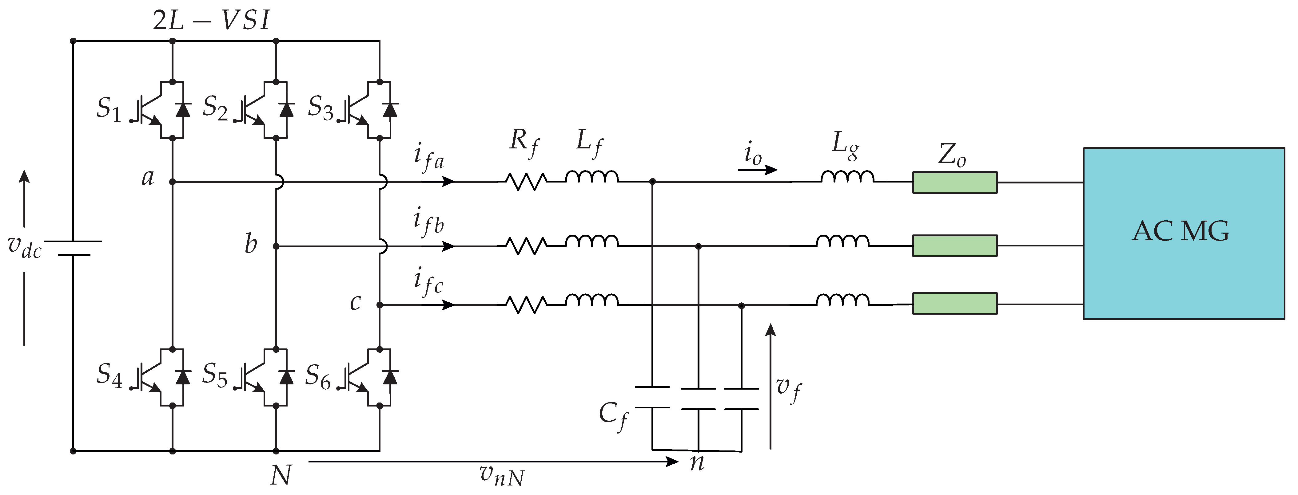
The power converter used in this research corresponds to a DC–AC-type power converter. This voltage source inverter has three legs, each with two power switches, MOSFETs. A diagram of the two-level three-phase VSI can be seen in Figure 2.
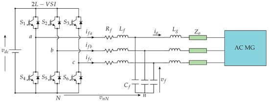
Figure 2.
Diagram of a two-level three-phase VSI with filter, coupled to an AC microgrid via distribution line with an impedance .
This equipment is capable of generating a three-phase PWM type voltage at the output or AC side, at the frequency established in the control [34,35].
For its operation, it must be considered that on the same leg, two switches must never be on, since the voltage source would be short-circuited. Furthermore, it is advisable to have both switches on the same leg off, because control over the current injected into the load can be lost [35].
This type of power converter is the most elementary and commonly utilised topology in AC microgrids. In Figure 2, an filter is connected at the terminals for attenuating the switching harmonics, allowing grid-forming operation, controlling capacitor voltage [33].
Considering the above information, for its correct use, in Table 1, valid combinations for the switches are shown. Mathematically, the voltage on the AC side, with respect to the negative voltage on the DC side, is given by the matrix of Equation (1).

Table 1.
Switch configurations and complex voltage vectors used in two-level three phase VSI.
The voltage vectors’ values obtained from (1) are shown in Table 1 according to the signals , , and . The two possible values that the gate signals can take are 1 or 0.
Then, the VSI can be in eight () possible switch configurations. Considering the neutral N from Figure 2, the voltage of each leg of the VSI can be obtained by multiplying the DC-link voltage with the state of the same VSI’s leg:
To obtain the effective voltages utilised across each phase, common mode voltage must be subtracted from Equation (2). By considering Kirchhoff’s voltage law, the common mode voltage can then be obtained using:
Then, the effective phase voltage are given by:
On the other side, to achieve favourable control performance for proposing a model predictive control, MPC, the two-level three-phase VSI will be modelled using a stationary orthogonal reference frame considering balanced conditions, using the amplitude invariant Clarke transformation from to reference frame as shown in Equation (5) [36].
The signal x in Equation (5) can be referred to as voltage or current signals. Consequently, expressions for the three-phase voltages v and currents i are as follows:
2.2. filter
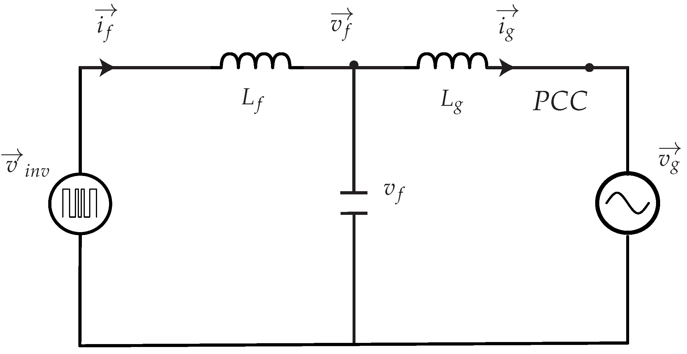
In Figure 2 the typical configuration of the two-level three-phase equipped with the filter can be seen. Through this filter, the power from the DG flows to the rest of the islanded AC microgrid. The used filter for each phase has its components defined as , , and , that are filter inductance, filter capacitance, and grid inductance, respectively. For sake of simplicity and further explanation, in Figure 3, the equivalent circuit in the stationary reference frame of the filter is shown. Then, the complex state variables are as follows:
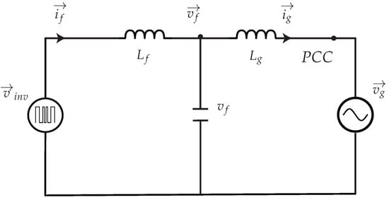
Figure 3.
Equivalent circuit of the VSI with the filter in the stationary reference frame.
The state-space model of the system in continuous-time can be explained considering Kirchhoff voltage and current laws:
where the state vector . The matrices A, B, and E are as follows:
and
with and are the equivalent series resistance of inductance and , respectively. Due to the small values of these resistances, they can be perfectly neglected for the design of the controller [37].
The continuous model of the system shown in Equation (8) may be discretised to get the predictive equation, for the application of a digitally implemented control law, as follows [37,38]:
with k as the present time instant. Considering that the sampling time is , the discrete matrices , , and can be described as:
and
and
3. Modulated Model-Predictive Control
3.1. Multiobjective Cost Function
A crucial portion of the MPC strategy is the determination of the cost function to evaluate the predictions against the references. Here, the control objectives are included. For this research, there are two control objectives: the capacitor voltage, , and the output current, .
In this way, the established multiobjective cost function is as follows:
where and are the weighting factors for the output current and capacitor voltage , respectively. and are the predicted values of the output current vector and the capacitor voltages obtained, respectively, and and are the output current reference and capacitor voltage reference, respectively.
3.2. Space Vector Modulation
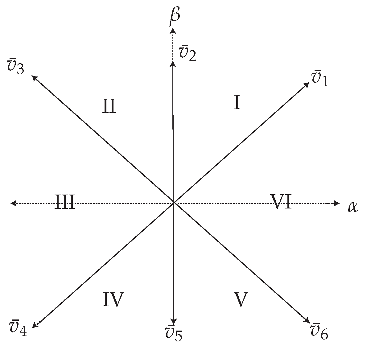
The developed MPC scheme includes a modulation stage [21,39]. The necessary modulation for the two-level three-phase VSI corresponds to the SVM algorithm in the reference frame. In Figure 4, the SVM can be seen; it is utilised to operate the VSI switches.
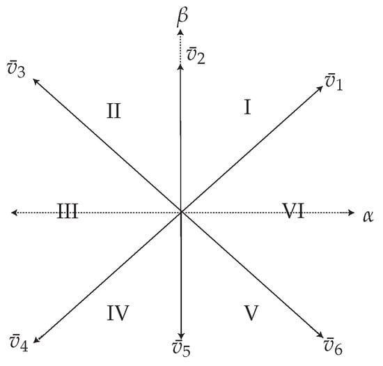
Figure 4.
Available vectors for the two-level three-phase VSI.
For each sector, , of the valid switching states of the two-level three-phase VSI, the capacitor voltage vectors for the next sampling time, (k + 1) and (k + 1), are predicted using the discrete-time mathematical model of the filter from Equation (12).
The prediction of the two active vectors that compose each sector at every sampling time are evaluated separately in the cost function defined in Equation (16).
Then, for calculating the duty cycles for each sector, , of the SVM, the following set of equations is solved:
where corresponds to the duty cycle of a zero vector which is evaluated once.
For finding the expression K, the system of equations in (17) are solved, thus providing the duty cycles for each vector, as follows:
From the equations in (18), the new cost function, which is assessed at every sampling instant, , is defined as:
The new cost function defined in (19) is evaluated and the two vectors that minimise it are applied to the power converter at the next sampling instant.
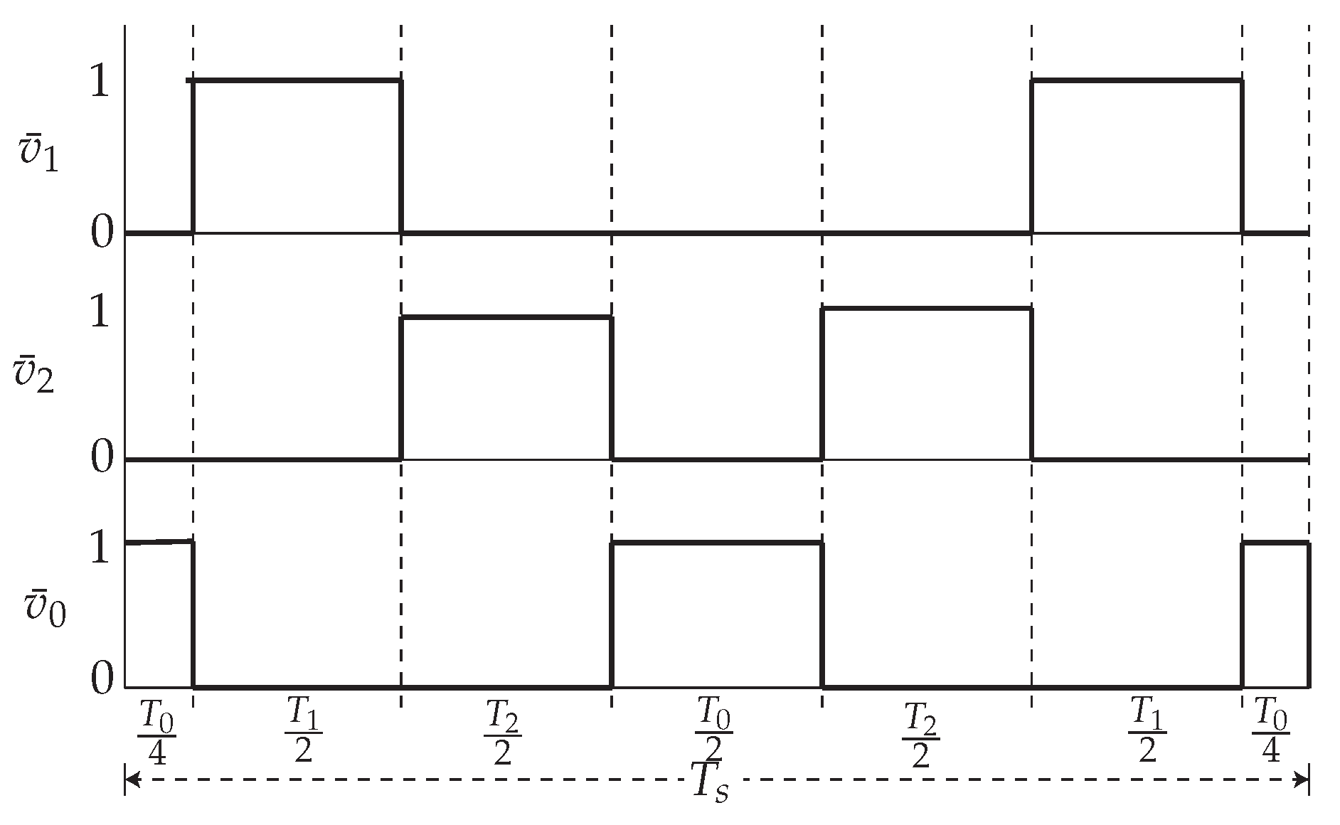
Once the duty cycles are obtained and the optimal vectors are selected to apply them, a switching sequence procedure, which can be seen in Figure 5, is utilised with the objective of applying the two active vectors and the two zero vectors [39].
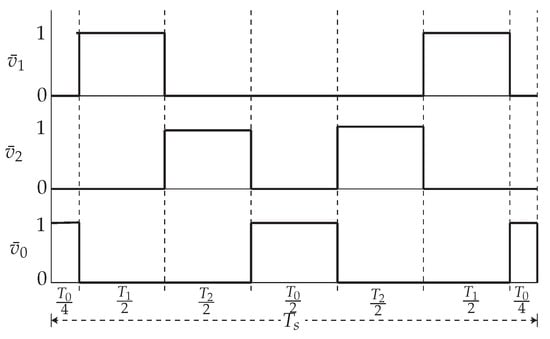
Figure 5.
Switching sequence procedure for the optimal vectors.
4. Alternating-Current Microgrids with Multiple MPC Regulated Voltage Source Inverters
4.1. Power Sharing Control
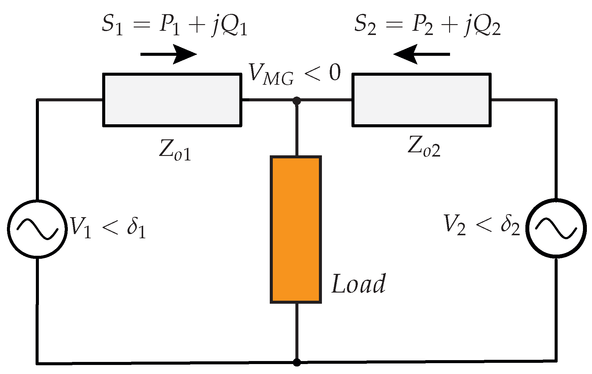
The diagram depicted in Figure 6 represents two VSIs sharing a common load connected to an AC microgrid bus through distribution lines with complex impedances, . For establishing the control strategy of these connected power converters, active and reactive power are exchanged through the distribution lines of the AC microgrid. Then, considering hierarchical control in microgrids, this power exchange can be regulated by power sharing control which can be classified as primary control [3,33,40].
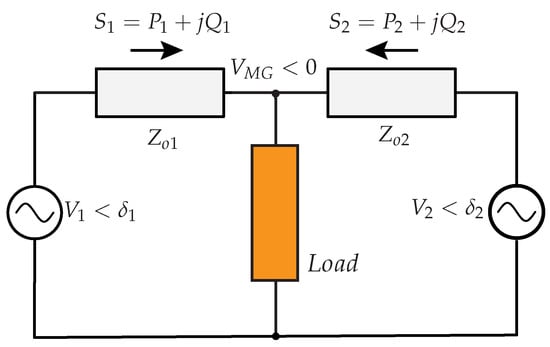
Figure 6.
Diagram of two VSIs sharing a load connected to an AC microgrid by way of complex impedances .
Power sharing control is implemented in grid-supporting power converters to keep the microgrid voltage frequency and amplitude under control [14]. Each inverter in the microgrid must have an external power loop based on droop control, also called decentralised control. One of the advantages of using this control is that it does not require communication among the inverters of the microgrid, eliminating the limits imposed by physical location of DGs in the microgrid and improving its performance [14,41].
Droop control is heavily influenced by the impedance values of the microgrid´s distribution lines. Given an ideal VSI that is coupled to the load via a given line impedance, , the active and reactive powers that the VSI will deliver to the grid are as follows [7]:
where and are the active and reactive powers, respectively, flowing from the source 1 (VSI) to 2, the grid, and are the voltage values of these sources. Furthermore, represents the phase-angle difference between the two voltages, and is the distribution line impedance [3,33,42].
As can be seen in Equations (20) and (21), and swap depends on both and ; therefore, these both powers are not able to be controlled independently by those variables [33,43]. A technique that is accepted to solve this issue is to enforce the effective output impedance seen by the VSI to become purely resistive or inductive via control efforts. This technique is known as virtual impedance [33,43].
4.2. Virtual Impedance
The output impedance, as seen by the VSI, determines the effectiveness of the power sharing [40]. It is more recommendable to shape the closed-loop output impedance to be resistive via the virtual impedance technique [7]. The virtual impedance concept is to mimic the outcome of an impedance, with the line current being injected back to compute the virtual impedance voltage drop [7]. It is this voltage drop that has to be subtracted from the capacitor voltage reference which is obtained from the droop control, to finally deliver the capacitor voltage reference [43]. For a system such as the islanded AC microgrid, it is valid to consider it a resistive system as there are small distance lines with low system-inertia [44,45].
Addressing the former, a resistive virtual impedance is considered and established for this research. Due to small distance distribution lines of a microgrid, this virtual resistance is not changed by frequency, allowing the complete frequency span to be included with a single feedback loop. This permits more versatile power sharing for nonlinear loads and throughout transient states. Furthermore, resistive virtual impedance sums up damping to the system, contributing to the microgrid system’s stability [33]. Then, the established strategy for the virtual impedance loop, follows the technique developed and used in [1,33], as follows:
with as the resistive virtual impedance, is the capacitor voltage reference to be sent into the cost function (16), while is the voltage reference obtained from the external droop control.
Then, considering that from Equation (22) is configured sufficiently high to turn the output impedance into mainly resistive, and assuming that the power angle is small between the voltage vectors at the VSI and the microgrid terminals, it can therefore be assumed that , , and . Then, Equations (20) and (21) can be rewritten as [1,33]:
4.3. Droop Control
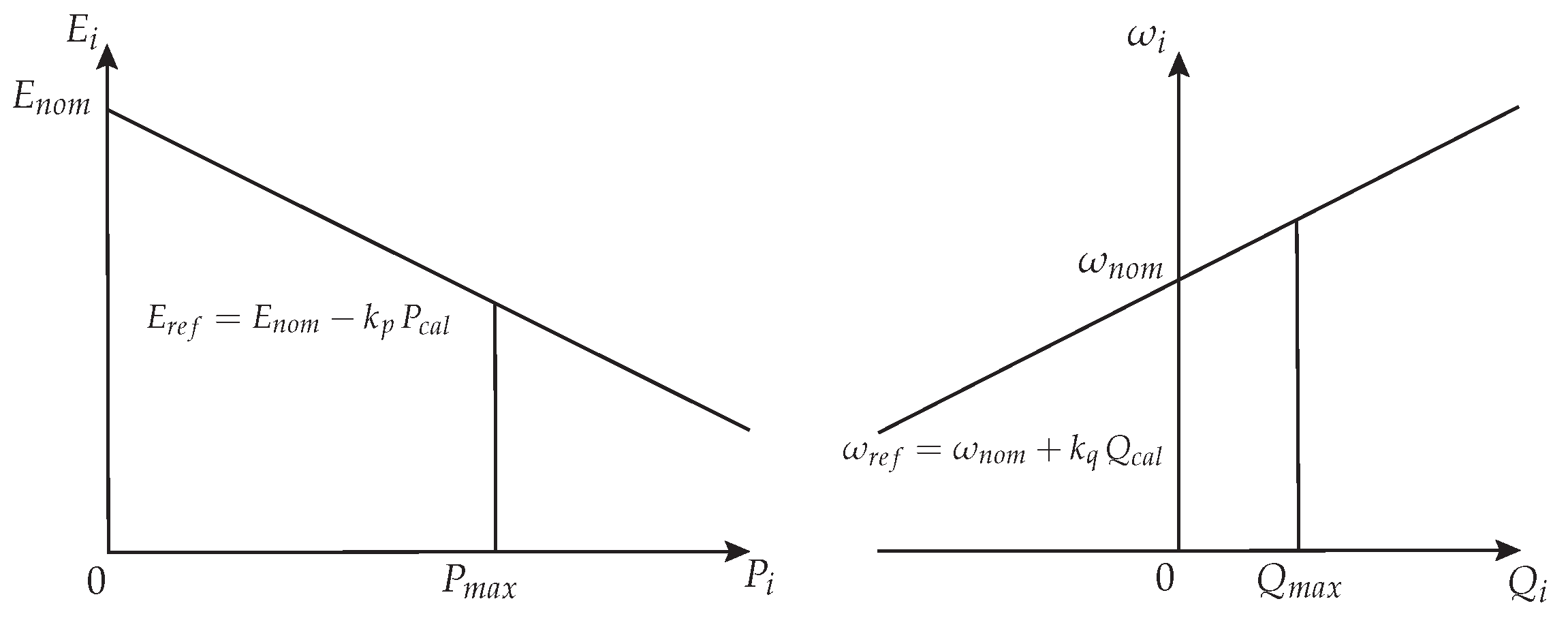
Subsequently, for establishing the outer droop control, and considering Equations (23) and (24), the droop control is designed using the following equations [1,33]:
where and are the reference voltage amplitude and frequency utilised to produce that is introduced to the virtual impedance loop from Equation (22), and with and are nominal voltage amplitude and frequency, respectively. As can be seen in Figure 7, the droop coefficients and define the droop curves, and thus, voltage drops and frequency boosts, given the resistive output impedance. Depending on the power rating of the VSIs or on the economical aspects of a given generation source, droop coefficients are determined proportionally [46,47]. Additionally, and are instantaneous active and reactive powers, and are obtained from the following equations [36]:
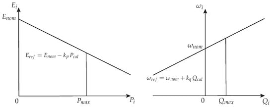
Figure 7.
Diagram of the resistive-based impedance droop control used in this study.
As mentioned in [1,33], and from Equations (27) and (28), respectively, must be damped via low-pass filters that normally have a smaller bandwidth order of magnitude than underlying loops in hierarchical linear control [3]. This may lead to a very slow transient reaction. By using MPC as the inner control scheme of each VSI in an AC microgrid, filtering is not necessary, since, in this case, the speed for the MPC technique is only restricted by the sampling time . Additionally, since the variations in and are softened by the droop coefficients, and , finally, the oscillations in and have an almost negligible effect on the calculation of and [1,33].
The droop control strategy described in Equations (25) and (26) is known as and droop control for resistive microgrids [44] or opposite droop control [48], which corresponds to the case of low-voltage grid with impedances being mainly resistive (), and, hence, the inductive component can be neglected. Due to low-voltage microgrids frequently have resistive output impedances, a droop feature that is based on an hypothesis of totally resistive output impedances may also be utilised [7].
This droop control allows for fully decentralised operation, with this representing one of the main advantages. Nevertheless, it also has some functional restrictions, such as steady-state deviation [1,33]. This issue has been considered in [49,50]; however, secondary control of microgrids usually needs extra low-bandwidth communication, an aspect that is beyond the scope of this work. For proving the droop control strategy in this work, the exposed droop control strategy is implemented to validate the concept.
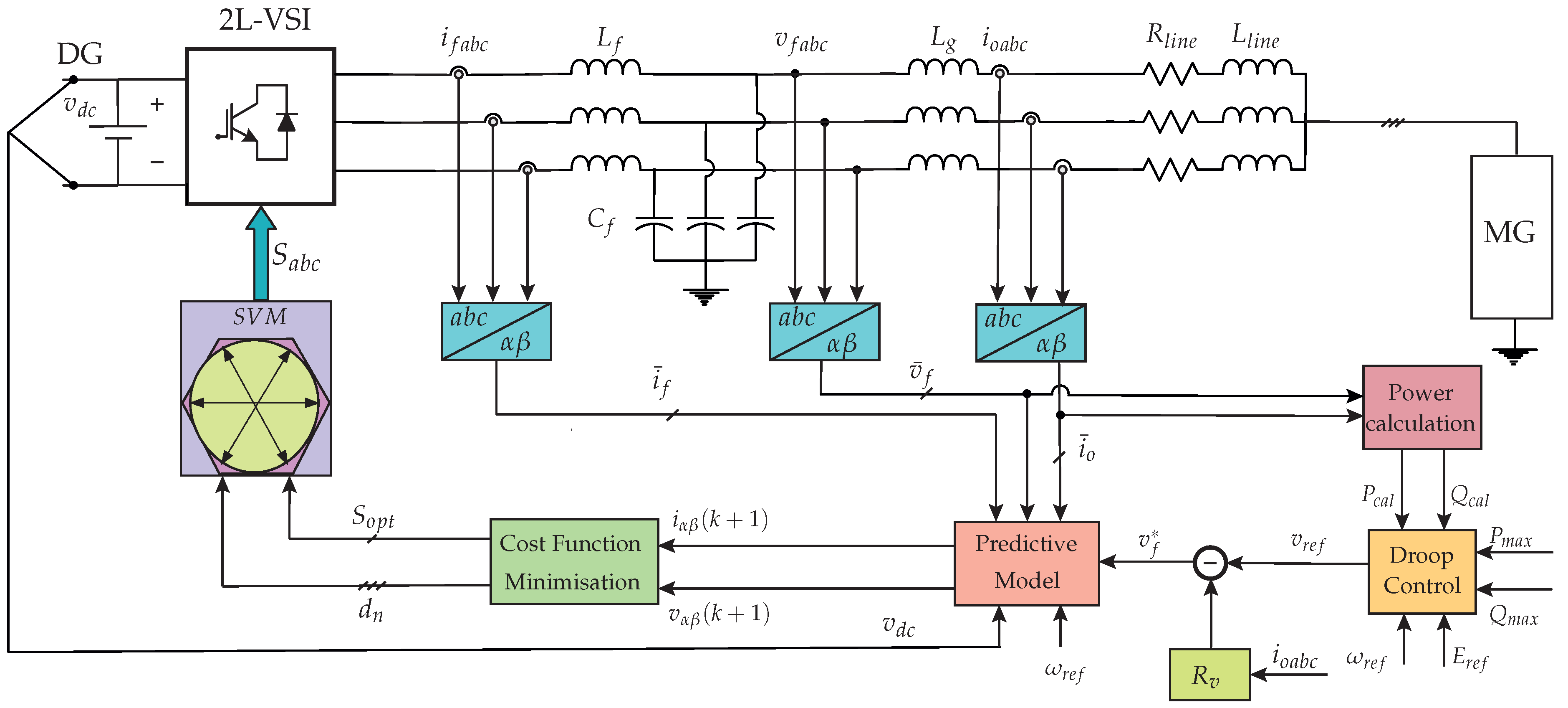
In Figure 8, all control structures of the methodology in this research are presented. The block diagram of the implementation of the proposed fixed-switching-frequency MPC scheme is shown along with its details. In this block diagram, it is clearly presented that the capacitor voltage reference introduced in the MPC algorithm is built by the droop controller plus the virtual impedance as described earlier in this section. The inner-controller of each VSI, as presented in Figure 8, is able to work independently from each other VSI in the islanded AC microgrid, operating in a decentralised manner. In the next section, simulation results for the islanded AC microgrid with paralleled -filtered VSIs, sharing a load and controlled by the proposed fixed-switching-frequency MPC inner-controller are presented.
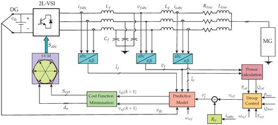
Figure 8.
Block diagram of the proposed modulated model predictive control scheme for a two-level three-phase -filtered VSI in an islanded AC microgrid.
5. Simulation Results
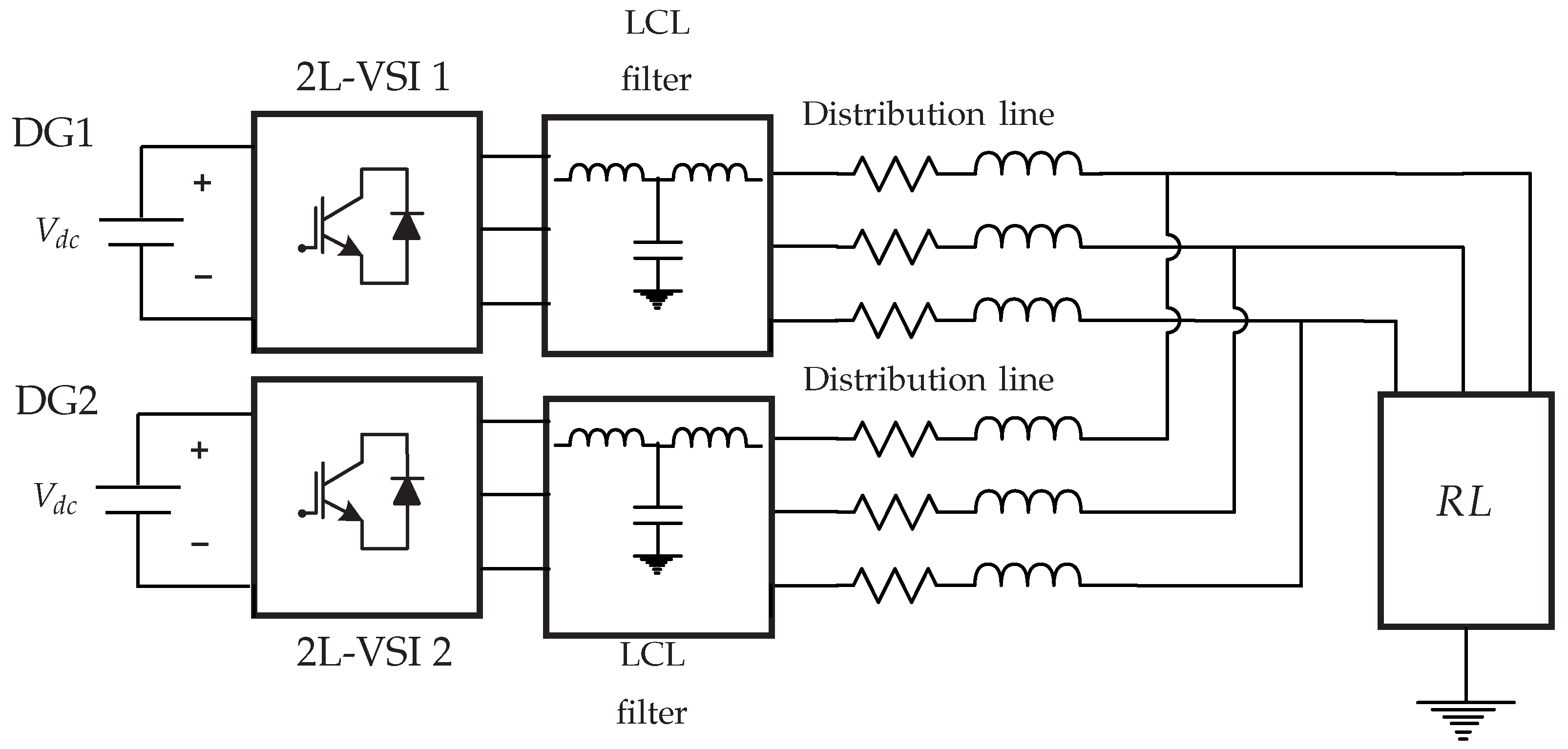
To corroborate the concept of the proposed control scheme, simulations in MATLAB/Simulink are carried out. The studied microgrid system consists of an isolated AC microgrid of two parallel -filtered VSIs, sharing an load, as shown in Figure 9. The parameters of the simulations are listed in Table 2. Nominal parameters and power ratings of the two DGs are chosen to be the same. Droop control with resistive virtual impedance external-loop is utilised to produce the voltage reference to feed the predictive model of the filter to evaluate the multiobjective cost function from Equation (16).
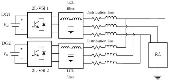
Figure 9.
Topology of the implemented islanded AC microgrid system.

Table 2.
Simulation parameters.
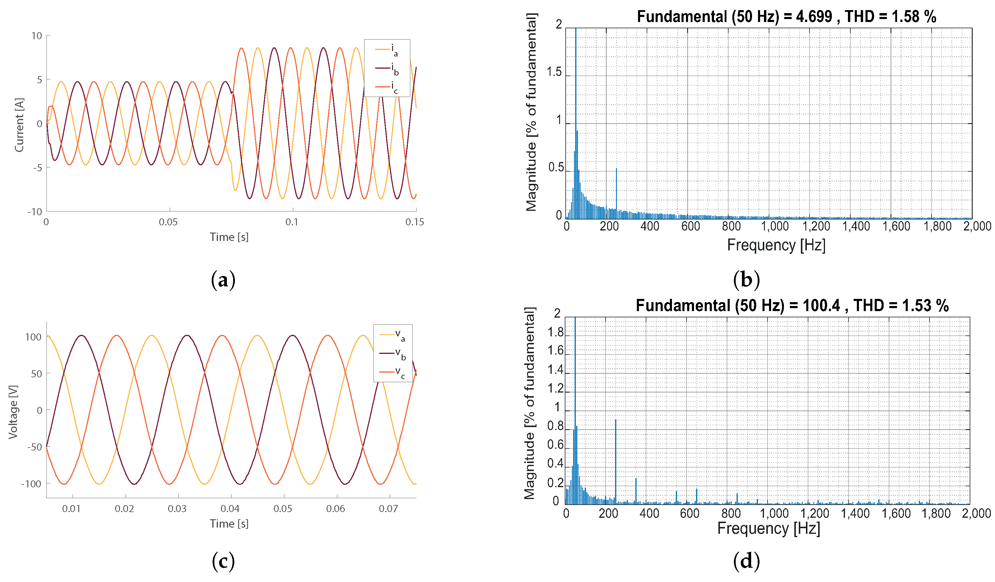
The simulation results are shown in Figure 10:
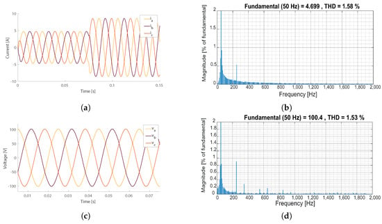
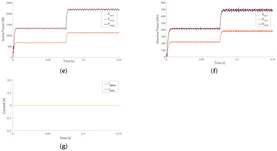
Figure 10.
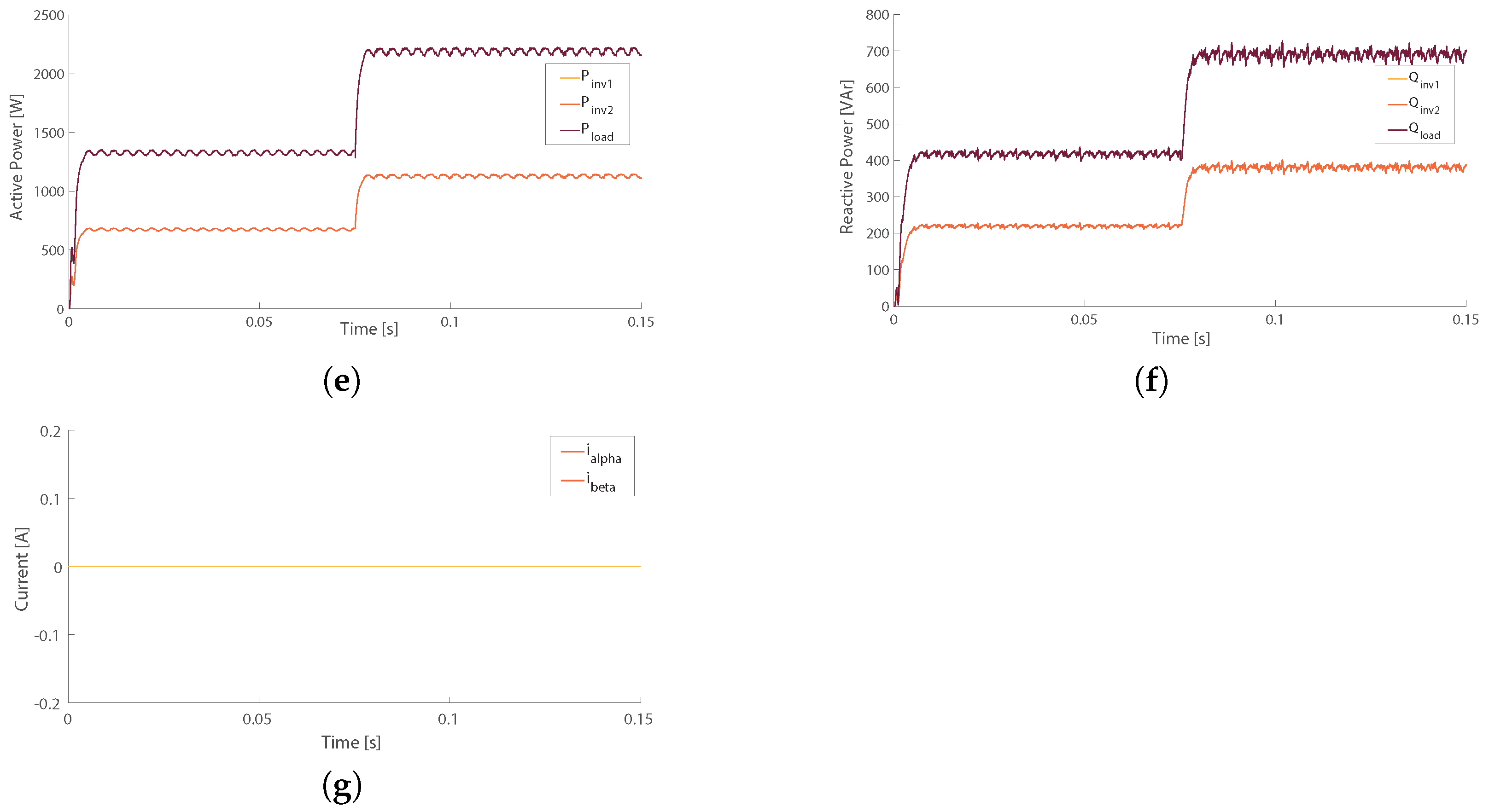
Simulations results for the AC microgrid with two paralleled two-level three-phase VSIs: (a) output current, , VSI 1 with load step-change at s, (b) THD of output current, phase a, , VSI 1 (considering no load step-change), (c) capacitor voltage, , VSI 1 (d) THD of capacitor voltage, phase a, , VSI 1, (considering no load step-change), (e) active power sharing performance between VSI 1 and VSI 2, , in the AC microgrid with load step-change at s, (f) reactive power sharing performance between VSI 1 and VSI 2, , in the AC microgrid with load step-change at s, and (g) circulating currents in the AC microgrid after applying virtual resistance, .
- In Figure 10e, the active power sharing of the load is shown. It can be seen that the active power is properly shared among the two inverters in the isolated AC microgrid as active power load is equally shared between the two VSIs. Additionally, at s the load step-change is shown.
- In Figure 10f, the reactive power sharing of the load is shown. It can be seen that the reactive power is properly shared among the two inverters in the isolated AC microgrid, as it is equally shared between the two VSIs. Additionally, at s the load step-change is shown.
- In Figure 10g, the circulating currents, and , are shown. It can clearly be seen that circulating currents are properly eliminated from the islanded AC microgrid system.
6. Experimental Results
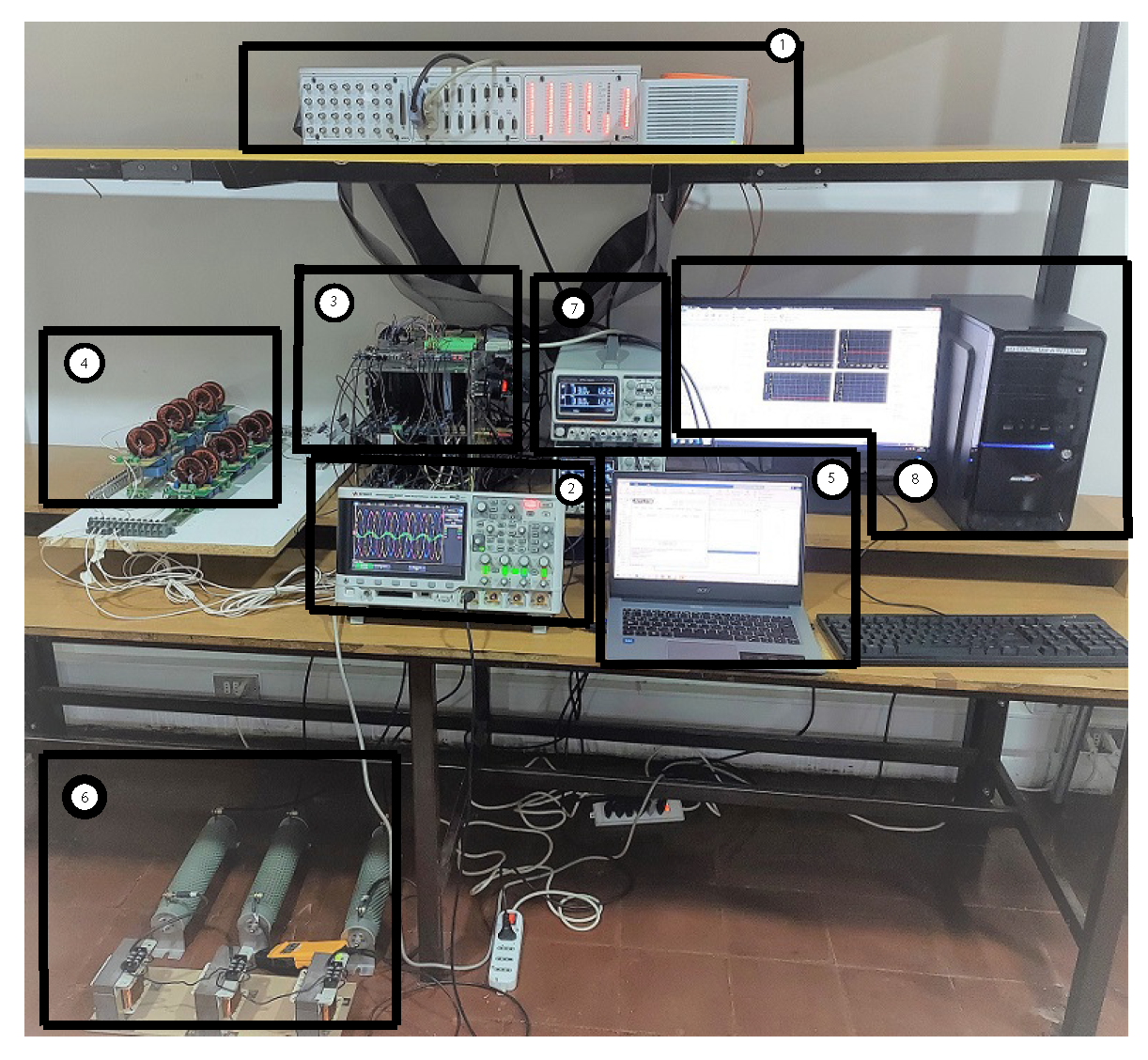
To verify the concept of the MPC applied to the islanded AC microgrid depicted in Figure 8, a hardware prototype with the two-level three-phase VSI shown in Figure 2 is implemented and tested in the laboratory. The hardware platform is shown in Figure 11.
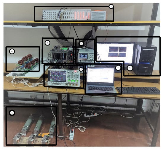
Figure 11.
Experimental setup: (1) dSPACE ds1103 control platform, (2) oscilloscope for signal acquisition, (3) two-level three-phase VSI, Atlys FPGA, DC input, (4) filters, (5) programming computer, (6) load, (7) controllable DC voltage source, (8) dSPACE platform’s programming computer.
The power converter implemented is depicted in Figure 2; the implemented power switches correspond to MOSFETs. The construction of the modulated predictive controller was realised in a dSPACE ds1103 control platform. An additional control board, based on a Xilinx Spartan-6 FPGA, Atlys, is connected to the I/O bus expansion available in the dSPACE ds1103 platform. The mentioned configuration can be seen in Figure 11. In order to generate the SVM, the slave DSP I/O available in the dSPACE ds1103 platform is used. In the dSPACE’s Simulink library, a block is available to generate the three-phase space vector PWM with original and inverted outputs and, if necessary, a variable deadband [51]. The dSPACE’s block that allows the establishment of the SVM is called ’DS1103SL_DSP_PWMSV’.
Once the six pulses are generated by the dSPACE ds1103 platform, they are fed into the Atlys FPGA board for adding the required dead-times in each of the MOSFETs legs. Finally, the generated six gate pulses are sent through optical fibre links to the MOSFET- gate drives.
ADC ports of the dSPACE ds1103 were used to obtain the readings of capacitor voltages, , filter currents, , and outputs currents, , from the two-level three-phase VSI, using voltage and current differential clamps.
The experimental setup used for proof-of-concept has the parameters shown in Table 3.

Table 3.
Experimental parameters.
7. Discussion
In both the simulation and implementation, the established control is capable of operating the system properly.
7.1. Simulation Results
The obtained simulation results depicted in Figure 10 show that the established fixed-switching-frequency MPC strategy for the output current, , works properly for the steady-state conditions and for the transient after a load step-change doubling the load (Figure 10a). The results of this output current phase a, , (Figure 10b) correspond to the fundamental current amplitude of 4.7 [A], and THD: 1.58%. For the capacitor voltage, , the waveforms are shown in Figure 10c, with values of fundamental voltage of 100.4 and THD: 1.53% (Figure 10d) which is comparably lower than those obtained, for instance, for the conventional FS-MPC scheme for VSI connected in an isolated AC microgrid (THD: 2.16%) [33].
In Figure 10e, the active power sharing of the load is shown. It can be seen that the active power is properly shared among the two inverters in the isolated AC microgrid. Additionally, at s the load step-change is shown; the active power sharing is properly kept among the two paralleled--filtered inverters. This active power sharing shows that the established droop control with virtual resistance also works properly.
In Figure 10f, can be seen that the reactive power is properly shared among the two inverters in the isolated AC microgrid. Additionally, at s the load step-change is shown; it can be seen that the reactive power sharing is properly kept among the two paralleled--filtered inverters. This reactive power sharing shows that the established droop control with virtual resistance also works properly.
In Figure 10g, the circulating currents, and , are shown. It can be seen that the circulating currents are eliminated from the isolated AC microgrid system, showing that the droop control and virtual resistance control strategies (Equations (22), (25), and (26), respectively,) work properly.
It is important to highlight that the precision of this active power sharing (Figure 10e) is higher than that obtained by the author in [33] [Figure 12], which uses modified FS-MPC for two converters connected in parallel. A similar conclusion can be drawn by analysing the results for the reactive power from Figure 10f, with a superior exactness of the reactive power sharing than that obtained using FS-MPC in [33] [Figure 13].
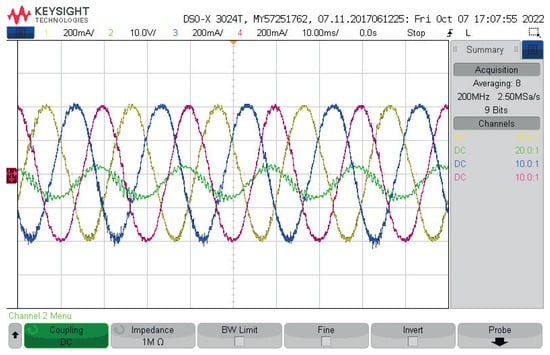
Figure 12.
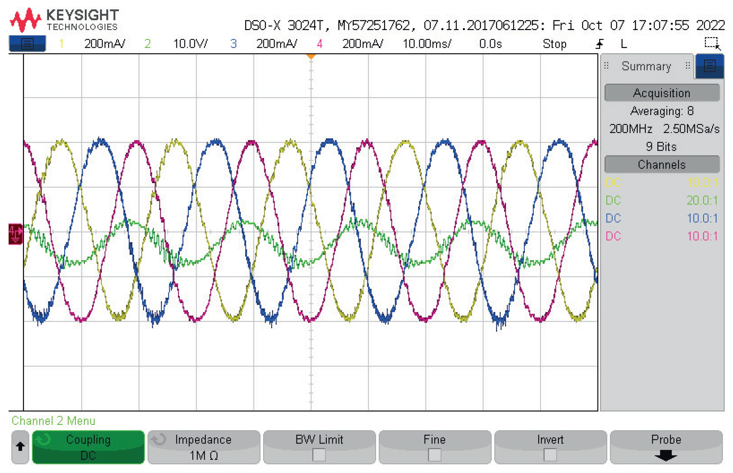
Experimental results: oscilloscope view of the output currents, , , , and capacitor voltage, of the two-level three-phase VSI using the proposed fixed-switching frequency control scheme in the islanded AC microgrid.
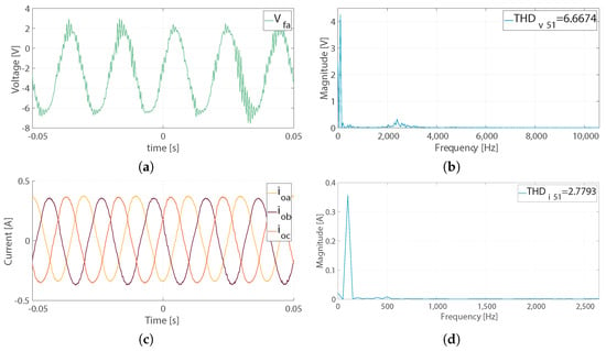
Figure 13.
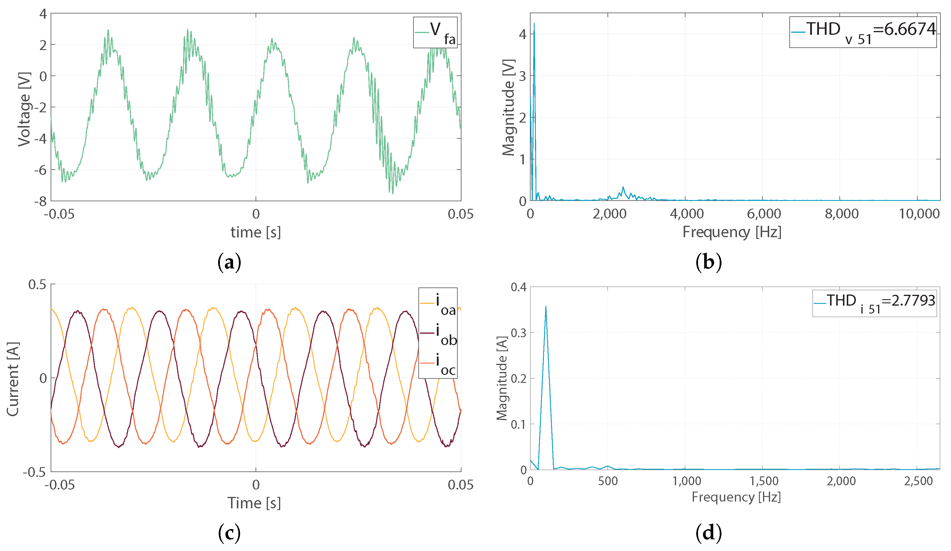
Experimental results for the two-level three-phase VSI: (a) capacitor voltage, , (b) THD of capacitor voltage, phase a, , (c) output current, , and (d) THD of output current, phase a, .
7.2. Experimental Results
The obtained experimental results are shown in Figure 12 and Figure 13. In Figure 13a, it can be clearly seen that the capacitor voltage, in this case for the phase a, is properly controlled as expected. In Figure 13b, the THD value is ≈ 6.6%, and is contained within the established limits of standard deviation of 519-2014. This value is not superior to those obtained with FS-MPC for paralleled power converters sharing a load [33]; however, it can be seen that the harmonics spectrum is not spread throughout all the frequencies which, as mentioned earlier, represents a main drawback of not fixing the frequency. As for islanded mode, low levels of THD are important, the usage of four-leg power converters may be relevant to provide better compensation for voltage unbalances [52].
For the experimentally obtained output currents, , the waveforms are shown in Figure 13c. The spectra analysis is shown in Figure 13d. There, it can be seen that the low-frequency harmonics in the currents (500 Hz) may be occasioned by the unbalance among the filters and the load. Additionally, the harmonics content is in the proximity of the limits of the 51st harmonics, with the currents bearing less distortion (≈ 2.8%) with attenuated high frequencies by the filter inductances and the microgrid system. Eventually, although beyond the scope of this work, this can be improved by establishing this control strategy in a four-leg power converter that allows current to pass through the neutral, and thus absorbing the unbalances of the system by controlling zero sequence currents [52,53,54].
The obtained experimental results clearly show that application of the fixed-switching-frequency MPC scheme controls the -filtered two-level three-phase VSI obtaining proper waveforms for the capacitor voltages and the output currents, while allowing balance across the whole microgrid system. The inclusion of a multivariable cost function allowed these waveforms to track their references coming from the outer primary control of the microgrid.
Inclusion of an filter for the implemented islanded AC microgrid may have advantages for a standalone system, especially if it is expected to bear a wide harmonic spectrum produced using FS-MPC [33]. As in this work, an MPC was implemented and this spectrum was expected to be concentrated in only certain frequencies, with the additional help of having the microgrid-side inductor, [55].
These results contribute to the literature in the field, with MPC algorithms to be more considered for further research and development in the field of power converters in microgrids, and thus proving the feasiblity of developing and applying MPC in this research field.
8. Conclusions
In this research, a fixed-switching-frequency MPC is established for the capacitor voltage control of an AC bus in an isolated AC microgrid system. This system bears a decentralised power sharing control that employs droop control combined with virtual resistance to balance the active and reactive power sharing between voltage source inverters. The isolated AC microgrid is hierarchically controlled: the inner-control for the voltage source inverter, and the primary control for the decentralised power sharing of the load.
Regarding the voltage source inverter, its control strategy is conceived as the inner-predictive controller. The voltage source inverter operates in an isolated AC microgrid connected through an filter to an load that may be shared with other voltage source inverters interfacing renewable-energy-based distributed generators. To ensure proper operation, this inner-predictive-controller must control the voltage in the capacitor of the filter and improve the injected current in the AC microgrid, the output current of the voltage source inverter. Thus, the inner controller design aims at achieving these two control objectives: the capacitor voltage, , and the output current, . The established cost function to be minimised then becomes a multiobjective one (Equation (16)). Next, for the space vector modulator, the vector region and duty cycles for each vector are found, evaluating the new cost function (Equation (19)) at every sampling time in order to minimise it. Subsequently, the generated six gate pulses are sent through optical fibre links to the MOSFET-gate drives.
The references for the inner-control are given by the primary control in the studied AC microgrid, with the voltage reference coming from the droop control with virtual resistance. In the hierarchical control of microgrids, references for frequency, voltage amplitude, active power, and reactive power would be provided by the secondary controller. Nevertheless, secondary control development lies beyond the scope of this study; thus, these references are taken as given.
The inner-control given by the fixed-switching-frequency modulated model predictive control exhibits improved performance in eliminating the drawbacks that classic predictive control may have: inclusion of harmonics across the whole frequency spectrum, among others. Additionally, it may allow for improved grid-connected operation with the -filtered voltage source inverters in the microgrid system. The primary control, the power sharing of the load, proved to operate properly in the isolated AC microgrid system and coordinated with the modulated model predictive inner-controller of the voltage source inverter. Thus, load is equally shared between the two voltage source inverters in the microgrid, and circulating currents are properly eliminated.
The research presented herein does not address the operation in grid-connected mode, where control objectives may change. Grid-connected systems work utilising different standards with distinct operation objectives as compared to islanded applications [33]. The implementation of a fixed-switching-frequency MPC algorithm may considerably improve coupling with the main grid, since the control and minimisation of harmonics content is an important requirement for its successful and proper operation [56].
On the other side, the development of multiobjective optimisation used in this research through the inclusion of the hybrid cost function, which contains the capacitor voltage and output current (microgrid current), was not proved in grid-connected mode. There is development in this field, for instance, the development of a multivariable hybrid cost function containing the grid current, inverter-side current, and capacitor voltage tracking, designed to stabilise an -filtered grid-connected inverter [37]. Operation of the studied microgrid system with paralleled VSIs under grid-connected mode using this hybrid predictive control approach, represents potential research topics to further the understanding of these control algorithms and systems.
As a multiobjective cost function was developed for this research, it was not part of the scope to analyse the weighting factors’ sensitivity, for instance, as the study carried out by [33]. Furthermore, it would be of interest to implement a cascaded MPC that allows control of the relevant parameters to enable proper microgrid operation, either in island mode or grid-connected mode, without using weighting factors. In this regard, an interesting work to note might be that carried out by [57].
Additionally, no delay compensation was used for the MPC algorithm in this research. It is expectable that adding delay compensation, eventually, will improve the obtained results. This would be something to realise in future research linked to this field.
Motivations for developing the proposed research can be summarised as follows:
- The incipient development of predictive control strategies for power sharing control of power converter-based microgrids can be spread to more MPC-based applications.
- Fixed-switching-frequency MPC schemes for power converters have the advantage of fixing the harmonic spectrum to a single frequency. Thus, problems with coupling between the different control levels could be avoided.
- Use of the MPC control strategy could ease the design of filters, and thus improve the operation of the whole system.
- Modulated model predictive control bears a robust control for the voltage tracking performance of the power converter, compared to classical predictive control strategies where the converters operate in parallel with a distributed droop controller.
- Finally, research in the field of droop control and virtual impedance could be favoured by the development and inclusion of new internal power converter control techniques.
For a clearer explanation of this work’s contribution compared with state-of-the-art developments on fixed-switching-frequency modulated model predictive control and microgrid applications, summary tables are presented below (Table 4, Table 5 and Table 6).

Table 4.
Summary of works on predictive control applied to microgrids.

Table 5.
Summary of works on predictive control applied to microgrids (cont. of Table 4).

Table 6.
Summary of works on predictive control applied to microgrids (cont. of Table 5).
Author Contributions
Conceptualisation, A.V., J.M., C.M. and M.R.; methodology, A.V. and C.M.; software, A.V. and C.M.; validation, J.M., C.M. and M.R.; formal analysis, A.V. and C.M.; investigation, A.V.; resources, A.V., J.M. and M.R.; data curation, A.V., C.M.; writing—original draft preparation, A.V.; writing—review and editing, A.V., C.M., J.M. and M.R.; visualisation, A.V. and C.M.; supervision, J.M.; project administration, A.V. and J.M.; funding acquisition, A.V. and J.M. All authors have read and agreed to the published version of the manuscript.
Funding
This research was funded by CONICYT PFCHA/Doctorado Becas Chile/2019—2119025 and the Agencia Nacional de Investigación y Desarrollo (ANID) FONDECYT Regular grant number 1191028. The work was also supported by Centre for Multidisciplinary Research on Smart and Sustainable Energy Technologies for Sub-Antarctic Regions under Climate Crisis ANID/ATE220023.
Conflicts of Interest
The authors declare no conflict of interest.
Abbreviations
The following abbreviations are used in this manuscript:
| AC | Alternating current |
| PCC | Point of common coupling |
| MPC | Modulated model predictive control |
| VSI | Voltage source inverter |
| MPC | Model predictive control |
| FS-MPC | Finite-set model predictive control |
| DG | Distributed generator |
| MG | Microgrid |
| SVM | Space vector modulation |
| SVPWM | Space vector pulse-width modulation |
| ANN | Artificial neural network |
| DBPC | Deadbeat predictive control |
| PDPC | Predictive direct power control |
| CF | Cost function |
| NPC | Neutral-point-clamped |
| MIMO | Multiple-input–multiple-output |
| LC | Inductor–capacitor |
| LCL | Inductor–capacitor–inductor |
| MOSFET | Metal–oxide–semiconductor field-effect transistor |
| PWM | Pulse-width modulation |
| DC | Direct current |
| RL | Resistor–inductor |
| DSP | Digital signal processor |
| THD | Total harmonic distortion |
| FPGA | Field-programmable gate array |
| I/O | Input-output |
| ADC | Analogue-to-digital-converter |
| C-OSS-MPC | Cascaded-optimal switching sequence model predictive control |
| MPC | Modified modulated model predictive control |
| ANN-MPC | Artificial neural network modulated model predictive control |
| N/A | Not applied |
References
- Chen, T.; Abdel-Rahim, O.; Peng, F.; Wang, H. An Improved Finite Control Set-MPC-Based Power Sharing Control Strategy for Islanded AC Microgrids. IEEE Access 2020, 8, 52676–52686. [Google Scholar] [CrossRef]
- Lei, M.; Yang, Z.; Wang, Y.; Xu, H.; Meng, L.; Vasquez, J.C.; Guerrero, J.M. An MPC-Based ESS Control Method for PV Power Smoothing Applications. IEEE Trans. Power Electron. 2018, 33, 2136–2144. [Google Scholar] [CrossRef]
- Villalón, A.; Rivera, M.; Salgueiro, Y.; Muñoz, J.; Dragičević, T.; Blaabjerg, F. Predictive control for microgrid applications: A review study. Energies 2020, 13, 2454. [Google Scholar] [CrossRef]
- Mannini, R.; Eynard, J.; Grieu, S. A Survey of Recent Advances in the Smart Management of Microgrids and Networked Microgrids. Energies 2022, 15, 7009. [Google Scholar] [CrossRef]
- Hou, X.; Sun, Y.; Lu, J.; Zhang, X.; Koh, L.H.; Su, M.; Guerrero, J.M. Distributed hierarchical control of AC microgrid operating in grid-connected, islanded and their transition modes. IEEE Access 2018, 6, 77388–77401. [Google Scholar] [CrossRef]
- Razmi, D.; Lu, T. A Literature Review of the Control Challenges of Distributed Energy Resources Based on Microgrids (MGs): Past, Present and Future. Energies 2022, 15, 4676. [Google Scholar] [CrossRef]
- Ghosh, A.; Zare, F. Control of Power Electronic Converters with Microgrid Applications, 1st ed.; Wiley: Hoboken, NJ, USA, 2023; pp. 1–538. [Google Scholar]
- Alhasnawi, B.N.; Jasim, B.H.; Issa, W.; Esteban, M.D. A novel cooperative controller for inverters of smart hybrid AC/DC microgrids. Appl. Sci. 2020, 10, 6120. [Google Scholar] [CrossRef]
- Babayomi, O.; Zhang, Z.; Dragicevic, T.; Hu, J.; Rodriguez, J. Smart grid evolution: Predictive control of distributed energy resources—A review. Int. J. Electr. Power Energy Syst. 2023, 147, 108812. [Google Scholar] [CrossRef]
- Alvarez-Diazcomas, A.; López, H.; Carrillo-Serrano, R.V.; Rodríguez-Reséndiz, J.; Vázquez, N.; Herrera-Ruiz, G. A novel integrated topology to interface electric vehicles and renewable energies with the grid. Energies 2019, 12, 4091. [Google Scholar] [CrossRef]
- Zhang, M.; Song, B.; Wang, J. Circulating Current Control Strategy Based on Equivalent Feeder for Parallel Inverters in Islanded Microgrid. IEEE Trans. Power Syst. 2019, 34, 595–605. [Google Scholar] [CrossRef]
- Tayab, U.B.; Roslan, M.A.B.; Hwai, L.J.; Kashif, M. A review of droop control techniques for microgrid. Renew. Sustain. Energy Rev. 2017, 76, 717–727. [Google Scholar] [CrossRef]
- Alghamdi, S.; Sindi, H.F.; Al-Durra, A.; Alhussainy, A.A.; Rawa, M.; Kotb, H.; AboRas, K.M. Reduction in Voltage Harmonics of Parallel Inverters Based on Robust Droop Controller in Islanded Microgrid. Mathematics 2023, 11, 172. [Google Scholar] [CrossRef]
- Hossain, M.A.; Pota, H.R.; Issa, W.; Hossain, M.J. Overview of AC microgrid controls with inverter-interfaced generations. Energies 2017, 10, 1300. [Google Scholar] [CrossRef]
- Murillo-Yarce, D.; Riffo, S.; Restrepo, C.; González-Castaño, C.; Garcés, A. Model Predictive Control for Stabilization of DC Microgrids in Island Mode Operation. Mathematics 2022, 10, 3384. [Google Scholar] [CrossRef]
- Rodríguez, J.; Cortés, P. Predictive Control of Power Converters and Electrical Drives. arXiv 2012, arXiv:1011.1669v3. [Google Scholar]
- Donoso, F.; Mora, A.; Cardenas, R.; Angulo, A.; Saez, D.; Rivera, M. Finite-Set Model-Predictive Control Strategies for a 3L-NPC Inverter Operating with Fixed Switching Frequency. IEEE Trans. Ind. Electron. 2018, 65, 3954–3965. [Google Scholar] [CrossRef]
- Ramirez, R.O.; Espinoza, J.R.; Villarroel, F.; Maurelia, E.; Reyes, M.E. A novel hybrid finite control set model predictive control scheme with reduced switching. IEEE Trans. Ind. Electron. 2014, 61, 5912–5920. [Google Scholar] [CrossRef]
- Cortes, P.; Rodríguez, J.; Quevedo, D.E.; Silva, C. Predictive current control strategy with imposed load current spectrum. IEEE Trans. Power Electron. 2008, 23, 612–618. [Google Scholar] [CrossRef]
- Bouafia, A.; Gaubert, J.P.; Krim, F. Predictive direct power control of three-phase pulsewidth modulation (PWM) rectifier using space-vector modulation (SVM). IEEE Trans. Power Electron. 2010, 25, 228–236. [Google Scholar] [CrossRef]
- Tarisciotti, L.; Zanchetta, P.; Watson, A.; Clare, J.C.; Degano, M.; Bifaretti, S. Modulated Model Predictive Control for a Three-Phase Active Rectifier. IEEE Trans. Ind. Appl. 2015, 51, 1610–1620. [Google Scholar] [CrossRef]
- Tarisciotti, L.; Zanchetta, P.; Watson, A.; Wheeler, P.; Clare, J.C.; Bifaretti, S. Multiobjective Modulated Model Predictive Control for a Multilevel Solid-State Transformer. IEEE Trans. Ind. Appl. 2015, 51, 4051–4060. [Google Scholar] [CrossRef]
- Yang, Y.; Wen, H.; Li, D. A Fast and Fixed Switching Frequency Model Predictive Control with Delay Compensation for Three-Phase Inverters. IEEE Access 2017, 5, 17904–17913. [Google Scholar] [CrossRef]
- Alhasheem, M.; Abdelhakim, A.; Blaabjerg, F.; Mattavelli, P.; Davari, P. Model predictive control of grid forming converters with enhanced power quality. Appl. Sci. 2020, 10, 6390. [Google Scholar] [CrossRef]
- Karamanakos, P.; Liegmann, E.; Geyer, T.; Kennel, R. Model Predictive Control of Power Electronic Systems: Methods, Results, and Challenges. IEEE Open J. Ind. Appl. 2020, 1, 95–114. [Google Scholar] [CrossRef]
- Xiao, D.; Alam, K.S.; Norambuena, M.; Rahman, M.F.; Rodriguez, J. Modified Modulated Model Predictive Control Strategy for a Grid-Connected Converter. IEEE Trans. Ind. Electron. 2021, 68, 575–585. [Google Scholar] [CrossRef]
- Karamanakos, P.; Nahalparvari, M.; Geyer, T. Fixed Switching Frequency Direct Model Predictive Control With Continuous and Discontinuous Modulation for Grid-Tied Converters With LCL Filters. IEEE Trans. Control Syst. Technol. 2021, 29, 1503–1518. [Google Scholar] [CrossRef]
- Bakeer, A.; Alhasheem, M.; Peyghami, S. Efficient Fixed-Switching Modulated Finite Control Set-Model Predictive Control Based on Artificial Neural Networks. Appl. Sci. 2022, 12, 3134. [Google Scholar] [CrossRef]
- Shan, Y.; Hu, J.; Li, Z.; Guerrero, J.M. A Model Predictive Control for Renewable Energy Based AC Microgrids Without Any PID Regulators. IEEE Trans. Power Electron. 2018, 33, 9122–9126. [Google Scholar] [CrossRef]
- Low, K.S.; Cao, R. Model predictive control of parallel-connected inverters for uninterruptible power supplies. IEEE Trans. Ind. Electron. 2008, 55, 2884–2893. [Google Scholar] [CrossRef]
- Tan, K.T.; Peng, X.Y.; So, P.L.; Chu, Y.C.; Chen, M.Z. Centralized control for parallel operation of distributed generation inverters in microgrids. IEEE Trans. Smart Grid 2012, 3, 1977–1987. [Google Scholar] [CrossRef]
- Dimeas, A.; Tsikalakis, A.; Kariniotakis, G.; Korres, G. Microgrids control issues. In Microgrids: Architectures and Control, 1st ed.; Hatziargyriou, N., Ed.; Wiley: Chichester, UK, 2014; Chapter Microgrids Control Issues; pp. 25–80. [Google Scholar] [CrossRef]
- Dragicevic, T. Model Predictive Control of Power Converters for Robust and Fast Operation of AC Microgrids. IEEE Trans. Power Electron. 2018, 33. [Google Scholar] [CrossRef]
- Wu, B.; Narimani, M. High Power Converters and AC Drives; John Wiley & Sons: Hoboken, NJ, USA, 2017; p. 451. [Google Scholar] [CrossRef]
- Sharkh, S.M.; Abusara, M.A.; Orfanoudakis, G.I.; Hussain, B. Power Electronic Converters for Microgrids, 1st ed.; Wiley: Singapore, 2014; pp. 1–293. [Google Scholar]
- Akagi, H.; Watanabe, E.H.; Aredes, M. Instantaneous Power Theory and Applications to Power Conditioning; John Wiley & Sons: Hoboken, NJ, USA, 2017. [Google Scholar]
- Xue, C.; Zhou, D.; Li, Y. Hybrid model predictive current and voltage control for LCL-filtered grid-connected inverter. IEEE J. Emerg. Sel. Top. Power Electron. 2021, 9, 5747–5760. [Google Scholar] [CrossRef]
- Osorio, C.R.D.; Schuetz, D.A.; Koch, G.G.; Carnielutti, F.; Lima, D.M.; Maccari, L.A., Jr.; Montagner, V.F.; Pinheiro, H. Modulated Model Predictive Control Applied to LCL-Filtered Grid-Tied Inverters: A Convex Optimization Approach. IEEE Open J. Ind. Appl. 2021, 2, 366–377. [Google Scholar] [CrossRef]
- Rivera, M. A New Predictive Control Scheme for a VSI with Reduced Common Mode Voltage Operating at Fixed Switching Frequency. In Proceedings of the 2015 IEEE 5th International Conference on Power Engineering, Energy and Electrical Drives (POWERENG), Riga, Latvia, 11–13 May 2015; IEEE: Riga, Latvia, 2015; pp. 617–622. [Google Scholar] [CrossRef]
- Villalón, A.; Muñoz, C.; Aliaga, R.; Muñoz, J.; Rivera, M.; Zanchetta, P. Power Sharing Control of Islanded AC Microgrid Considering Droop Control and Virtual Impedance. In Proceedings of the 2020 IEEE International Conference on Industrial Technology (ICIT), Buenos Aires, Argentina, 26–28 February 2020; pp. 1139–1144. [Google Scholar] [CrossRef]
- Wu, X.; Shen, C.; Iravani, R. A Distributed, Cooperative Frequency and Voltage Control for Microgrids. IEEE Trans. Smart Grid 2018, 9, 2764–2776. [Google Scholar] [CrossRef]
- De Brabandere, K. Voltage and Frequency Droop Control in Low Voltage Grids by Distributed Generators with Inverter Front-End. Ph.D. Thesis, Katholieke University Lueven, Leuven, Belgium, 2006. [Google Scholar]
- Dragicevic, T.; Li, Y. AC and DC Microgrid Control. In Control of Power Electronic Converters and Systems: Volume 2, 1st ed.; Blaabjerg, F., Ed.; Elsevier: London, UK, 2018; Chapter 18; pp. 167–200. [Google Scholar] [CrossRef]
- Bevrani, H.; Francois, B.; Ise, T. Microgrid Dynamics and Control, 1st ed.; John Wiley & Sons: Hoboken, NJ, USA, 2017; p. 684. [Google Scholar] [CrossRef]
- Heydari, R.; Savaghebi, M.; Blaabjerg, F. Virtual Inertia Operation of Renewables; Academic Press: Cambridge, MA, USA, 2021; Volume 3, pp. 523–540. [Google Scholar]
- Dragičević, T. Dynamic Stabilization of DC Microgrids with Predictive Control of Point of Load Converters. IEEE Trans. Power Electron. 2018, 33, 10872–10884. [Google Scholar] [CrossRef]
- Hu, L.; Lei, W.; Li, R.; Gao, Y. A Graphic Weighting Factor Design Method for Finite Control Set Model Predictive Control of Power Converters. IEEE J. Emerg. Sel. Top. Power Electron. 2022, 1. [Google Scholar] [CrossRef]
- Holvik, A.B. Virtual Impedance Techniques for Power Sharing Control in AC Islanded Microgrids. Master’s Thesis, Norwegian University of Science and Technology, Trondheim, Norway, 2018. [Google Scholar]
- Mahmood, H.; Michaelson, D.; Jiang, J. Accurate reactive power sharing in an islanded microgrid using adaptive virtual impedances. IEEE Trans. Power Electron. 2015, 30, 1605–1617. [Google Scholar] [CrossRef]
- Li, Z.; Zang, C.; Zeng, P.; Yu, H.; Li, S. Fully distributed hierarchical control of parallel grid-supporting inverters in islanded AC microgrids. IEEE Trans. Ind. Inform. 2018, 14, 679–690. [Google Scholar] [CrossRef]
- dSPACE. DS1103 R&D Controller Board: RTI Reference; dSPACE: Paderborn, Germany, 2014; pp. 1–110. [Google Scholar]
- Khan, I.; Vijay, A.S.; Doolla, S. Nonlinear Load Harmonic Mitigation Strategies in Microgrids: State of the Art. IEEE Syst. J. 2022, 16, 4243–4255. [Google Scholar] [CrossRef]
- Rivera, M.; Yaramasu, V.; Rodriguez, J.; Wu, B. Model predictive current control of two-level four-leg inverters -Part ii: Experimental implementation and validation. IEEE Trans. Power Electron. 2013, 28, 3469–3478. [Google Scholar] [CrossRef]
- Yaramasu, V.; Rivera, M.; Narimani, M.; Wu, B.; Rodriguez, J. Model predictive approach for a simple and effective load voltage control of four-leg inverter with an output LC filter. IEEE Trans. Ind. Electron. 2014, 61, 5259–5270. [Google Scholar] [CrossRef]
- Chen, X.; Wu, W.; Gao, N.; Liu, J.; Chung, H.S.H.; Blaabjerg, F. Finite control set model predictive control for an LCL-filtered grid-tied inverter with full status estimations under unbalanced grid voltage. Energies 2019, 12, 2691. [Google Scholar] [CrossRef]
- Liu, B.; Zhou, D.; Blaabjerg, F. Advanced Modeling and Control of Voltage Source Converters with LCL Filters; Academic Press: Cambridge, MA, USA, 2021; pp. 221–268. [Google Scholar]
- Mora, A.; Cárdenas-Dobson, R.; Aguilera, R.P.; Angulo, A.; Donoso, F.; Rodriguez, J. Computationally Efficient Cascaded Optimal Switching Sequence MPC for Grid-Connected Three-Level NPC Converters. IEEE Trans. Power Electron. 2019, 34, 12464–12475. [Google Scholar] [CrossRef]
Disclaimer/Publisher’s Note: The statements, opinions and data contained in all publications are solely those of the individual author(s) and contributor(s) and not of MDPI and/or the editor(s). MDPI and/or the editor(s) disclaim responsibility for any injury to people or property resulting from any ideas, methods, instructions or products referred to in the content. |
© 2023 by the authors. Licensee MDPI, Basel, Switzerland. This article is an open access article distributed under the terms and conditions of the Creative Commons Attribution (CC BY) license (https://creativecommons.org/licenses/by/4.0/).

