Article

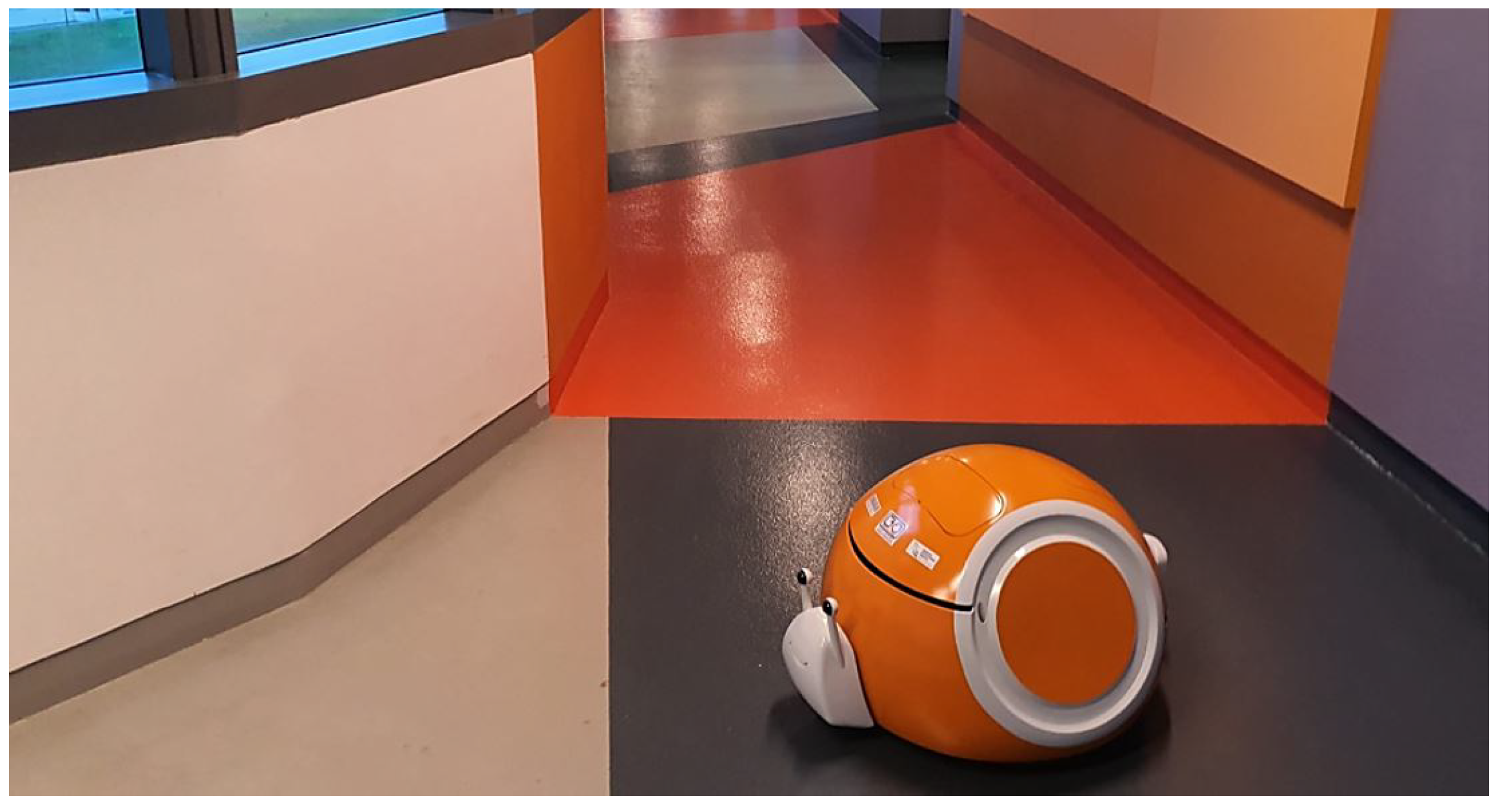
Snail: An Eco-Friendly Autonomous Steam Mopping Robot for Cleaning and Disinfection of Floors

by
Sathian Pookkuttath
1,
Mohan Rajesh Elara
1,
Madan Mohan Rayguru
2,
Zaki Saptari Saldi
3,
Vinu Sivanantham
1 and
Balakrishnan Ramalingam
1,*
1
Engineering Product Development Pillar, Singapore University of Technology and Design (SUTD), Singapore 487372, Singapore
2
Electrical Engineering, Delhi Technological University, New Delhi 110042, India
3
Product Design Engineering, Universitas Prasetiya Mulya, Tangerang 15339, Indonesia
*
Author to whom correspondence should be addressed.
Mathematics 2023, 11(5), 1086; https://doi.org/10.3390/math11051086
Submission received: 11 January 2023 / Revised: 8 February 2023 / Accepted: 13 February 2023 / Published: 22 February 2023
(This article belongs to the Topic Safe and Secure Autonomous Systems)

Abstract

:
Steam mopping is an eco-friendly solution for cleaning and disinfecting floors, avoiding harsh chemicals or harmful UV lights. Currently, commercial steam mopping systems are manually operated, which is laborious and unsafe. This work presents the design methodology of a novel, eco-friendly autonomous steam mopping robot named ‘Snail’ for cleaning and disinfecting typical indoor floors, namely tile, carpet, concrete, vinyl, sealed wood, and rugs. Our work is mainly focused on (1) the mechanical system design, including the locomotion, steam dispenser, and mopping unit, (2) the hardware and software architecture, and (3) the motion control system’s design for smooth maneuverability and mitigating friction forces. A high-gain friction estimator is proposed, whose output is exploited by the motion controller to follow the desired path and compensate for the traction-based locomotion disturbances due to extensive mop contact with a rough-textured floor, such as carpet. The proposed autonomous steam mopping robot’s efficiency is validated with different floors with zig-zagging cleaning patterns, setting a minimum of 100 °C as the disinfecting steam criterion. Using the proposed motion control algorithm, we validate the smooth maneuverability, assuring the robot traverses with a given speed and follows the trajectory even on a rough carpeted floor. The cleaning efficiency is tested by removing hard stains, consuming less water, and faster wet floor drying. The robot used only one liter of water to clean a 5  m 2  floor area, and the drying time was found to be four times faster than normal water mopping. The proposed steam mopping robot design is ideal for cleaning and disinfecting hospitals and eldercare centers, where hygiene is crucial, and promoting going green, avoiding harsh chemicals, and mitigating current cleaner labor concerns, including the risk of infection.

1. Introduction

Two emerging concepts, green cleaning and designing for the environment, are essential today to sustaining human life and environmental quality. Viral outbreaks such as COVID-19 demand frequent cleaning and disinfection. People move away from cleaning jobs not only due to their dull and repetitive nature but also due to the risk of infection. At the same time, the high growth of building infrastructure demands more cleaning forces to keep the environment eco-friendly. Unfortunately, the availability of the cleaning workforce has become tougher, considering cost, quality, and efficiency [1]. Floors contribute to a significant part of the indoor environment and become an indirect mode of transmission for viruses or other diseases [2]. This makes cleaning tasks more challenging, especially in crowded places such as malls, restaurants, airports, hospitals, educational institutes, eldercare centers, and recreational centers. Even today, many cleaning service industries rely on harsh chemicals for cleaning and disinfecting floors, which are costly, require more caution, and are harmful to the cleaners and the environment [3]. Alternatively, replacing chemicals with the ultraviolet light range of 100–280 nm is effective for disinfection but harmful to human eyes and skin unless the utmost care and protection are considered, as discussed in [4,5,6,7,8]. Hence, a safe and eco-friendly automated disinfection method is essential to clean and disinfect floors, especially in large human-shared workplaces.
Steam mopping is an effective solution for adequate disinfection, avoiding harsh chemicals and harmful UV lights. Steam mopping offers better hygiene and superior cleaning performance to conventional manual cleaning methods with detergents. As steam mopping uses only clean water, steam cleaners have become a favorite cleaning method for many people with allergies, asthma, and chemical sensitivities. When used correctly, steam can quickly kill 99.99% of germs and bacteria, making it a safe, healthy, and natural way to clean the environment. Various clinical tests have been conducted in the literature, proving the disinfection efficacy of steam and advantages over chemicals, especially in [9,10,11,12,13,14,15,16,17]. Based on these published works, a minimum steam temperature of 100  ° C is mandated for effective disinfection. Other than disinfection efficiency, the water consumption can be reduced by 90% through using steam, as briefed in [15]. In addition, as steam is used in a superheated state, it helps to remove hard stains, and the floor will dry around 3–6 times faster [18] than usual water mopping. Hence, steam is an effective medium for floor cleaning and disinfection tasks.
Steam mopping has been rising in popularity over the past few years. Many manually operated pieces of steam mopping equipment are commercially available [19,20,21,22]. However, it is hard to ensure the steam disinfection temperature and uniform dissipation throughout the mopping pad in a manual system. Other concerns with manual steam mops are burning hazards from the pad, handling long, tedious power cables, and heated long handles. Hence, an autonomous steam mopping device is a viable solution to overcome this shortcoming. Currently, several vacuum- or water-based mopping and scrubbing autonomous floor-cleaning robots at the domestic [23,24] and industrial grades [25,26] are available in the market. Additionally, many research works have been written on developing cleaning robots to improve the performance of floor cleaning in various aspects. Prabakaran et al. presented hTetro, a reconfigurable floor-cleaning robot that maximizes the coverage area, in [27]. Based on the environment, this robot can change its morphology to seven shapes, and a performance comparison was carried out with other fixed-shape platforms. Tun et al. presented enhanced maneuverability of the hTetro robot through a four-wheel steering and driving mechanism in [28] with a kinematic controller design. Similarly, various studies developed cleaning robots for other building domains, such as staircases [29,30], windows [31], walls [32,33], door handles [34], and tables [35].
The commercially available floor-cleaning robots and state-of-the-art cleaning performance explained above were developed based on vacuum- or water-based technologies for cleaning, mopping, and scrubbing. To extend floor disinfection application, the current practices using UV- and chemical-based solutions have their risk factors for usage and are not eco-friendly. Hence, a steam mopping autonomous robot is an optimal solution and essential today to mitigate the cleaning labor issues and viral outbreaks and strive for the green cleaning concept. However, for a steam-based mopping and disinfection robot, effective steam dissipation assuring a disinfection temperature with minimum energy consumption is crucial. In addition, while increasing the mopping pad size for better area coverage, the extensive friction raised at the mopping pad–floor interface (especially rough carpeted floors) affects the robot’s maneuverability and ability to follow a given cleaning pattern. As per our knowledge, no studies have been conducted considering these factors (research gaps) to develop a steam mopping autonomous robot suitable for large workplaces (i.e., more toward industrial-grade than domestic use). Hence, this work presents an autonomous steam mopping robot design and addresses the design challenges, including developing a low-power steam dissipation system, assuring a minimum steam dissipation temperature, designing a suitable motion controller for smooth maneuverability of the robot, and overcoming the extensive friction from the mopping pad while cleaning rough floors. The main research contributions of this work are the following:
  • Develop an autonomous mopping robot with steam as a cleaning payload for cleaning and disinfecting typical indoor floors as a safe and eco-friendly solution;
  • Design a steam mopping unit with a low power-rated compact steam generation unit and maximum mopping pad size to reduce energy consumption and increase area coverage while keeping the disinfection parameters;
  • Develop a novel motion controller design for smooth maneuverability to mitigate the friction forces, especially while mopping rough floors such as carpets;
  • Validate the uniform steam dissipation, maintaining the dissipation temperature, maneuverability following a given trajectory, and cleaning efficiency by testing with a zig-zagging cleaning pattern for real-time application, especially where hygiene is critical.
The outline of this paper is as follows. Section 2 elaborates on the design methodology, including the mechanical, system architecture, and motion controller design. Section 3 presents the steam modeling and experimental set-up with the results. Finally, Section 4 concludes with a summary of the paper.

2. Design Methodology of the Autonomous Steam Mopping Robot (Snail)

The outlook of the in-house developed, eco-friendly autonomous steam mopping robot, named ‘Snail’, is shown in Figure 1. The three design phases involved in realizing this robot were mechanical system design, hardware and software architecture design, and motion controller design. The detail of each design phase and its integration are described below.

2.1. Mechanical System Design

The exploded view and subassembly CAD model of the steam mopping robot, showing the structure and indicating the key components, is shown in Figure 2. The robot’s overall size is 75 × 60 × 40 cm, and the total weight is 20 kg. The main assembly of the robot is segmented into three layers: bottom, middle, and top. Here, the bottom layer is the mopping unit assembly. The middle layer is a ruggedized skeleton made of a 3 mm aluminum base plate and extruded profiles where the wheels, motors, controllers, sensors, and steam generation units are assembled. The top layer carries a battery, inverter, LiDAR sensor, and water tank. The robot locomotion was designed with a differential drive mechanism, and it uses wheels 150 mm in diameter made of solid rubber with an aluminum die-casted rim and two supporting caster wheels. Two 24 volt brushless DC geared motors with 1.9 N-m of torque were used to power the wheels separately with a closed-loop control function. For proper navigation of the robot, an inertial measurement unit (IMU) and time of flight (TOF) sensors were fastened to the middle layer base plate of the robot. Here, the IMU is placed at the center portion of the two-wheel axis, and the TOF sensors are placed facing toward the ground. Furthermore, the electronic components include an NVIDIA Jetson AGX Xavier onboard processor, Arduino microcontroller, and voltage regulators, which are also mounted to the middle layer. Two waterproof sonars are mounted on both sides of the robot cover toward the rear. The slit designed in the snail cover enables LiDAR coverage of 210°. Furthermore, the lids of the robot cover allow easy access to the water tank and electronics control. The outer Snail shape’s protective cover was 3D printed using ABS resin, and it can be easily removed to replace the mop. Here, the overall size of the robot is bulky compared with domestically used mopping robots, mainly due to the higher-capacity battery and inverter required for a tetherless steam-generating system. In addition, the outlook shape we designed as a snail took up more space. Here, we opted for a snail outlook because the robot prefers to run slower, allowing sufficient exposure per unit area (mopping pad size) for adequate disinfection. Additionally, it temporarily leaves a water trail mark while traveling, resembling a snail. This size and outlook will help highlight the robot’s presence in a large, crowded workplace, avoiding accidents and being aesthetically pleasing. The mechanical design of the cleaning payload is detailed below.

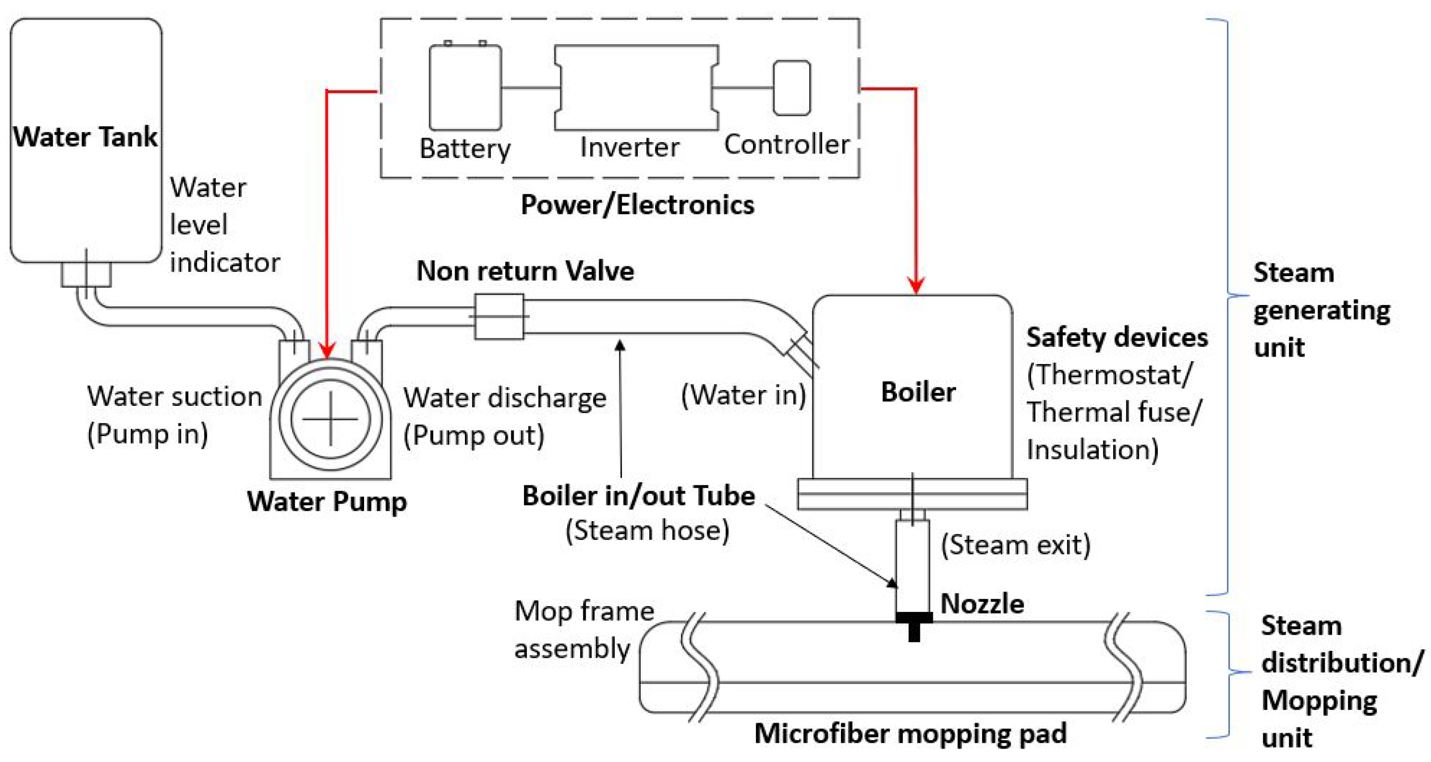
2.1.1. Steam Generation Unit

The steam generation unit is designed to provide continuous steam of 100  ° C at the mop–floor interface for effective disinfection. A lower power of 1300 W and two bar absolute pressure-rated compact boiler were selected to balance energy consumption and meet the disinfection temperature requirements. The boiler system also includes a thermostat, thermal fuse, and an insulated casing for safety. A 0.5 L water tank, 30 mL/min discharge-rated peristaltic water pump, and a non-return valve were used to regulate the water supply using silicon rubber tubes. The boiler and pump operations, including the water level, are controlled by an Arduino mega microcontroller. The water level sensor will trigger an alarm once the water level falls below 20% of the tank capacity. A 24 V, 40 Ah Li-ion rechargeable battery is used to power the heater unit, which is capable of discharging 1300 W of power using a 2000 W inverter. The same battery was used for powering the rest of the other systems. The steam generation and distribution process flow diagram is shown in Figure 3.

2.1.2. Steam Distribution Unit

A microfiber material is used for the mopping pad, with a designed size of 30 × 30 cm. The microfiber material has high heat retention [36,37] and durability. The mopping pad was connected with the boiler unit using a synthetic braid flexible butyl rubber hose capable of holding around 6 bar of steam pressure and a temperature of around 165  ° C. Furthermore, a twin-nozzle module was designed with two separate arms and a heat-resistant nylon material nozzle bracket for effective steam dissipation. The two arms of the nozzle are joined with a nozzle bracket sandwiched between a mop bracket and a mop plate. The mop bracket, plate, and frame were fabricated using heat-resistant polypropylene material. The proposed twin-nozzle design is shown in Figure 4.
The mopping unit is equipped with a steam temperature-sensing system to assure a uniform disinfection temperature of 100  ° C at the mop. Two thermocouple sensors, sensing a range of 600  ° C, were used to monitor the steam temperature. The sensors are housed in the mop bracket, and the probes are mounted at the two diagonal corners of the mop plate toward the mop. This helps with monitoring the target steam dissipation temperature across the mop. The sensors are connected to an Arduino UNO microcontroller. Furthermore, an auto-adjustable mop–floor contact-sensing system is integrated to maintain the mop’s pressure with various floors, uneven surfaces, or any tiny floor material. Figure 5 depicts these two systems. In addition, a TOF sensor (range: 4–30 cm), mounted at the base plate and facing the floor, reads and stores the distance to the particular floor once the initial mop–floor contact set-up is complete. Furthermore, suppose there is any change in this initial TOF sensor reading due to an uneven surface or ground material. In this case, a micro linear actuator with feedback will trigger to auto-adjust the mop level. This linear actuator (22 N and 30 mm stroke) is mounted with a base plate and mopping unit. A roboclaw motor controller is used to update the actuator motion with the Arduino UNO microcontroller. The whole mechanism helps to adjust the mopping unit height up to 9 mm, aided with guide bushes and pins.

2.2. System Architecture Design

The system architecture, mainly the hardware and software architecture of the steam mopping robot, is illustrated in Figure 6 and explained as follows.

2.2.1. Hardware Architecture

The hardware architecture of the steam mopping robot has two processing units: an Nvidia Jetson AGX Xavier single-board computer (SBC) and Arduino UNO embedded microcontroller. The Nvidia Jetson AGX Xavier SBC is used as the central processing unit. It handles navigation- and perception-related tasks. RPLIDAR A2, Vectornav IMU VN-100, and SONAR sensors are used for mapping and perception. The Arduino UNO microcontroller acts as an embedded microcontroller that handles lower-level control tasks. It monitors and controls the steam mopping unit and manages the steam temperature’s fixed threshold level. A water level indicator, thermocouples, and a TOF sensor are connected to the Arduino microcontroller, which are used to monitor the mopping unit’s operation and control.

2.2.2. Software Architecture

The Robot Operating System (ROS) melodic framework was used to build the software modules and also act as the middleware to support and establish communication between other hardware units and software packages. The navigation stack and control system stack of the robot were build on top of ROS. The higher-level systems such as the 2D LIDAR, IMU, and motor controllers are directly connected through SBC using ROS nodes, which publish the sensor data in their corresponding ROS topics to support the navigation stack and control stack. The ROS Navigation Stack was adopted to implement the autonomous navigation, which subscribes the motor controller feedback, IMU feedback, and fusion with an extended Kalman fiter (EKF) to estimate the odometry data and uses an adaptive Monte Carlo localization (AMCL) package for the robot’s localization. A move base package plans the path (global planner) and avoids the obstacles present on the map, and a local planner controls the robot to avoid dynamic obstacles by aligning the robot’s motion with the generated global path. The Cartographer SLAM algorithm was used to generate a 2D occupancy grid map of the environment and for autonomous navigation. The control system stack manages the navigation goal and executes the trajectory algorithm to continuously monitor the state of the robot from the high-level sensor and lower-level sensors connected to the robot. Based on the feedback from the sensors, the control system stack fine-tunes the robot trajectory.

2.3. Control System Design

One challenge in the locomotion of this steam mopping robot is the extensive friction from the pad–floor interface due to the 30 × 30 cm large mopping pad size designed for maximum coverage, especially while mopping rough-textured carpets. Opting for a higher-power torque-rated motor or friction modeling with necessary sensors will add to the cost. Therefore, a trajectory-tracking algorithm is proposed, which consists of a high-gain friction estimator in tandem with a PD controller.
The differential drive mechanism adopted for the Snail robot is illustrated in Figure 7, with the inverse and forward kinematic equations used for the robot’s maneuverability followed by an illustration of the motion controller’s design.
With inverse kinematics, the left and right wheel tangential velocities can be found (Equation (1)) by applying the target linear and rotational velocities of the robot:
v l = ( 2 v ω L ) 2 v r = ( 2 v + ω L ) 2
The control inputs the linear and angular velocities (v and  ω , respectively), which are found as shown in Equation (2):
v = r 2 ( φ ˙ r + φ ˙ l ) ω = r L ( φ ˙ r φ ˙ l )
As the pose (X, Y, and  θ ) functions depend on the functions of both the linear and angular velocities at time t, the new pose of the robot in the inertial frame is represented by
X ( t ) = 0 t v ( t ) cos [ θ ( t ) ] d t Y ( t ) = 0 t v ( t ) sin [ θ ( t ) ] d t θ ( t ) = 0 t ω ( t ) d t
The forward kinematics of the robot can be derived by expressing  X ( t ) , Y ( t ) , and  θ ( t )  from Equation (3) in differential form (position vector):
p ˙ = X ˙ Y ˙ θ ˙ = c o s ( θ ) 0 s i n ( θ ) 0 0 1 v ω
The mopping robot has to travel some predetermined path for satisfactory coverage. Hence, the motion control objective is to choose a suitable pair ( v , ω ) such that a desired path ( x d ( t ) , y d ( t ) ) can be followed, starting from an arbitrary position ( X ( 0 ) , Y ( 0 ) ). Given a desired path, the orientation  θ d ( t )  can be derived from  x d ( t )  and  y d ( t ) . Hence, the trajectory tracking task can be fulfilled by enforcing  x x d  and  y y d . The kinematics involving only X and Y can be written as
X ˙ Y ˙ = c o s ( θ ) 0 s i n ( θ ) 0 v ω
The problem with the model in Equation (5) is that we cannot uniquely determine ( v , ω ) from a particular ( X ˙ , Y ˙ ) pair due to the singularity in the system matrix (uncontrollable dynamics). To remove the singularity in Equation (5), we can differentiate the L.H.S. of Equation (5) as shown in Equation (6):
X ¨ = v ˙ c o s ( θ ) v s i n ( θ ) ω Y ¨ = v ˙ s i n ( θ ) + v c o s ( θ ) ω
After rearranging, the new motion model can be expressed as
X ¨ Y ¨ = c o s ( θ ) ζ s i n ( θ ) s i n ( θ ) ζ c o s ( θ ) f ω = Θ U
where  U = [ f , ω ] R 2  is the transformed control input pair and  Θ  is the new input matrix. Note that the linear velocity v and angular velocity  ω  are functions of the wheel velocities  v l  and  v r , respectively (check Equation (1)). Thus, Equation (7) can also be expressed in terms of the wheel velocities. The control input f is the linear acceleration, which is realized by
ζ ˙ = f , v = ζ
The compensator in Equation (8) is nothing but an integrator defined in the time domain. Note that the issue of singularity is resolved in Equation (7) with the new control pair. For an inversion-based control law, we have
U = Θ 1 ( ξ )
The system in Equation (7) is converted into a decoupled linear form:
X ¨ Y ¨ = ξ
where  ξ = [ ξ 1 , ξ 2 ] T  can be chosen as the simple PD feedback to solve the tracking problem for Equation (7).
However, the above control law does not consider any uncertainties in the acceleration of the robot described through Equation (7). The presence of a large mop may add significant friction (especially with carpet) to any acceleration in the X and Y directions. Therefore, a more practical model of the robot can be written as
X ¨ Y ¨ = ξ 1 + d x ξ 2 + d y
where  d x  and  d y  are the lumped uncertainties which may arise due to the variation in the friction forces from the mopping. In this regard, it is not conservative to assume that the variation in the friction forces with respect to time is slow. This leads to the following assumption:
Assumption 1. 
| | d ˙ x | | 0 , | | d ˙ y | | 0 .
To perfectly track a desired path, the impact of the uncertainties must be mitigated. Therefore, a fast disturbance estimator is proposed in the form of
μ d ˙ 1 = ( d 1 + 1 μ X ˙ + ξ 1 ) μ d ˙ 2 = ( d 2 + 1 μ Y ˙ + ξ 2 ) d ^ x = d 1 + 1 μ X ˙ d ^ y = d 2 + 1 μ Y ˙
where  μ ( 0 , 1 )  is called the perturbation parameter, ( d 1 , d 2 ) are intermediate variables, and  ( d ^ x , d ^ y )  are estimates of the uncertainties. Note that Equation (13) is the dynamics for the proposed disturbance observer. The outputs of the observer are the estimates of disturbances  d x  and  d y . The chosen parameter  μ  should be sufficiently small, depending on the sampling constraints. It can be derived that
μ d ^ ˙ x = d x d ^ x μ d ^ ˙ y = d y d ^ y .
The output of the estimator is fed to the controller, which is proposed in the form of
ξ 1 = x ¨ d k 1 e ˙ x k 3 e x ξ 2 = y ¨ d k 2 e ˙ x k 4 e y f ω = Θ ^ 1 ξ 1 d ^ x ξ 2 d ^ y v = ζ
where  k i , i = 1 , 2  are positive scalars acting as controller gains and the error variables are  e x = X x d  and  e y = Y y d .
With the control law (Equation (15)), the closed loop dynamics become
e ¨ x = k 1 e ˙ x k 2 e x + d x d ^ x e ¨ y = k 3 e ˙ y k 2 e y + d y d ^ y μ d ^ ˙ x = d x d ^ x μ d ^ ˙ y = d y d ^ y
which is in the form of a standard singularly perturbed model, with the error dynamics as a slow subsystem and the estimator dynamics as a fast subsystem.
Using the singularly perturbed technique and the smallness of  μ , it can be derived that the fast estimator dynamics have a unique isolated root in the form of
d x d y = d ^ x d ^ y .
In other words, for a small enough  μ , the estimated uncertainties will be equal to the actual uncertainties. If this root is substituted into the slow tracking dynamics, then the terms ( d x d ^ x ) and ( d y d ^ y ) will be zero. Hence, the tracking error dynamics become
e ¨ x = k 1 e ˙ x k 2 e x e ¨ y = k 3 e ˙ y k 2 e y .
The dynamics in Equation (18) are a stable Hurwitz system, and thus the tracking errors converge to zero such that
e x 0 , e y 0 .

3. Experiments, Simulations, and Discussion

The experimental section mainly validates the uniform steam dissipation, attaining the disinfection temperature, motion controller design mitigating the friction to follow the given trajectory, and cleaning efficiency as follows.

3.1. Evaluation of the Steam Temperature and Dissipation

The evaluation of the uniformity of steam dissipation at the disinfection temperature was conducted in two phases, including a steam flow simulation test and real-time steam flow dissipation test with a mopping pad.

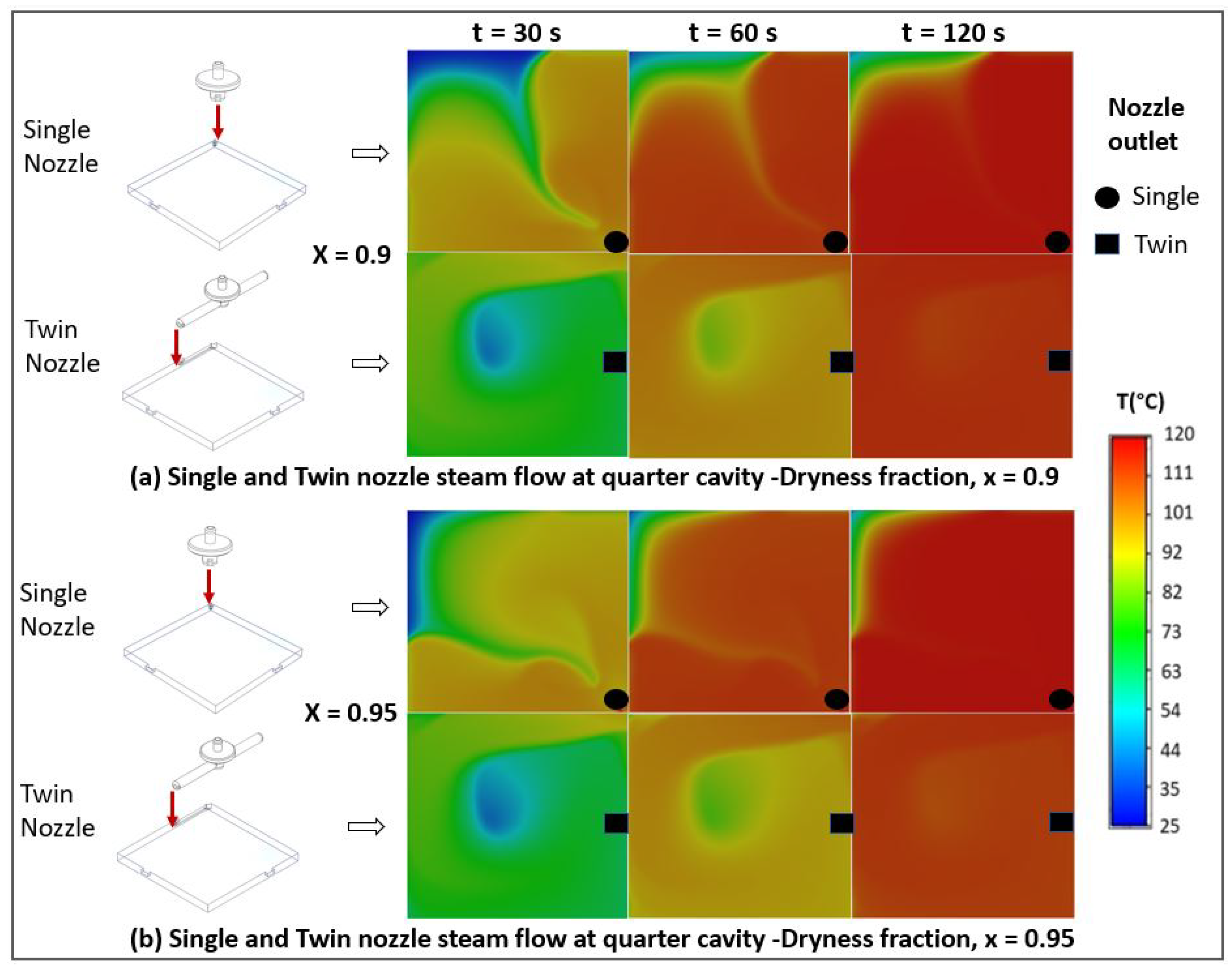
3.1.1. Steam Flow Simulation

A steam flow simulation was conducted to evaluate the uniformity of steam dissipation in the cavity above the mop. The simulation was based on the transient Euler–Euler multi-phase mixture model on ANSYS Fluent 2020 R2 to treat the transport of two interpenetrating continuum fluids, namely air and steam. Turbulence was accounted for using the k ϵ  Reynolds-averaged Navier–Stokes (RANS) model.
Superheated steam or saturated dry steam with a dryness fraction value X = 1 (no water droplets) is the ideal condition for the best steam performance for effectively removing dirt and disinfection. The dryness fraction (X) denotes the steam quality, and as per the standard definition, it is the ratio of the mass of dry steam to the combined mass of dry steam and mass of liquid in the mixture. However, due to the turbulence and splashing, environmental conditions, nozzle design and material etc., water molecules condense quickly, and hence steam often has water droplets. Thus, the steam’s dryness fraction may vary from 0.90 to 0.95. Therefore, we tested these two dryness fraction conditions to validate our steam generation and dissipation design, assuring that the disinfection criterion (minimum 100  ° C) was attained across the whole mopping pad area.
A quarter of the cavity was taken as the computational domain due to the symmetry in both lateral directions. A velocity magnitude equivalent with a steam flow rate of 2.2 kg/h, a steam volume fraction of 1.0, pressure of 2 bar, and temperature of 120  ° C was imposed at the nozzle, as per the boiler selected for the Snail robot. Furthermore, a pressure outlet was imposed at the two small lateral outlets. The side boundaries were treated as walls with a convective heat transfer coefficient of 10 W/m 2 -K and ambient temperature of 25  ° C at the outer side. The top and bottom boundaries were assumed to be thermally insulated. The simulations were performed for four study cases (i.e., combination of steam qualities ( X = 0.9  and  X = 0.95 ) and nozzle designs (single and twin)). The thermal properties (density, specific heat capacity, thermal conductivity, enthalpy, and dynamic viscosity) were calculated based on the steam quality. The physical simulation time was set to 120 s.
The steam properties were calculated based on the saturated water and saturated vapor properties at a pressure of 2 bar and the steam quality via the following expression:
SP = SP g X + ( 1 X ) SP l
where  SP  denotes the steam properties,  SP l  represents the properties of saturated water,  SP g  represents the properties of saturated vapor, and X is the steam quality.
Figure 8 shows the steam dissipation at different time instants for the two steam qualities and the two nozzle designs. For each plot, the top left area corresponds with the corner. The bottom right area corresponds with the nozzle’s location in the single nozzle case. In the twin nozzle case, the nozzle inlet was positioned at almost half the distance from the bottom right to the top right corner. With the twin nozzle set-up, a temperature of around 100  ° C was reached at the corner after 120 s for both steam qualities, which was not the case for the single nozzle.
The high corner temperature in the twin nozzle case was allowed by the steam jet impingement on the wall, owing to the nozzle position. The impinged heat-carrying jet was then deflected toward the corner, leading to a rotating convective flow. With the single nozzle, the steam tended to flow more radially without rotation around the corner. The rotating flow in the twin nozzle case enhanced the heat transfer throughout the cavity, as shown by the higher rate of temperature increase. This was also evident through the more uniform high temperature distribution at 120 s. The twin nozzle set-up also worked equally effectively for the two steam qualities, hence being more favorable than the single nozzle set-up.

3.1.2. Real-Time Steam Flow Test

A steam dissipation real-time test was conducted to assure uniform steam dissipation across the mopping pad–floor interface meeting the disinfection temperature. Here, the onboard thermocouple sensors monitor the steam temperature at the inner side of the moping pad. Hence, two additional thermocouple sensors were mounted diagonally on the floor (matching the pad’s corners) to measure the steam temperature at the pad–floor interface in the extreme corners. The test was conducted on tile, carpet, concrete, vinyl, wood, and rug floors at room temperature (around 25  ° C). Figure 9 shows the test set-up for the carpet floor. Accordingly, on the carpet, rug, and wooden floors, the steam temperature reached 100  ° C within 115–125 s, whereas for the vinyl, tile, and concrete floors, this took 125–135 s. The onboard sensors read the maximum temperature of 105  ° C at the this longest time period of 135 s. Hence, the target steam temperature for the onboard sensors was fixed at 105  ° C for both the initial set-up and while mopping.

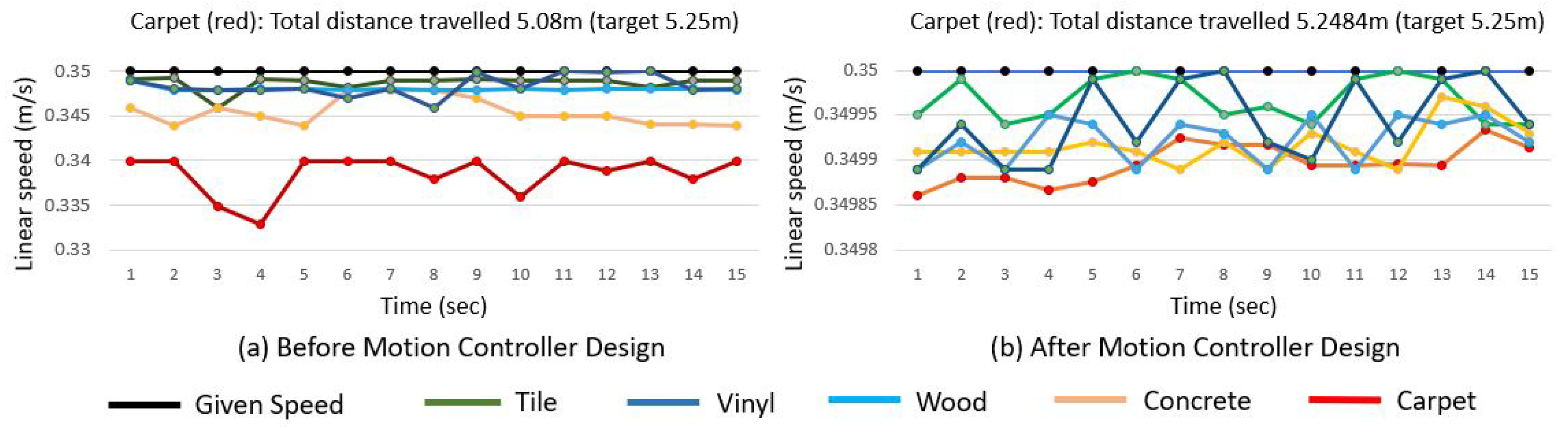
3.2. Motion Controller Performance Analysis and Comparison

To validate the motion controller performance, traverse speed feedback, and how closely the robot followed the given trajectory, tests were conducted before and after motion controller execution. The tests were conducted on tile, carpet, concrete, vinyl, and wooden floors at different linear and angular speeds (0.02–0.4 m/s and 0.2–1.0 rad/s, respectively). The tests were conducted at room temperature (25  ° C) while assuring that the onboard thermocouple sensors and linear actuator mechanism were working correctly to maintain the steam disinfection temperature and constant mop contact with the floor before starting each test. In the robot’s traverse feedback test, the actual velocities of the robot for each motion were recorded from the motor controller feedback and compared with the given velocity at every second. Accordingly, without a motion controller, there was obvious lagging, especially while driving through rough carpets, due to friction and wheel slippage. Figure 10 shows the traverse feedback test conducted at a linear speed of 0.35 m/s for 15 s before and after implementing the motion controller design. For the carpet, the actual velocity dropped to 0.335 m/s most of the time, which was improved to be very close (0.349 m/s) to the given velocity before and after the motion controller design, respectively.
Furthermore, consistent lane tracking to avoid any deviation from the given path was tested on the same types of floors. A test bed size of a 1.2 × 4.2 m area was selected, and a 2D map of this test bed environment was generated using Cartographer SLAM to follow the planned path in a zig-zagging pattern using the waypoint coordinates of the map. Figure 11 shows this test bed’s details together with the test results for a smooth concrete floor and rough carpet (the two extreme conditions) with and without executing the proposed motion controller (i.e., comparing the basic PID controller with this friction-estimated improved motion controller design). The motion controller comparison results are plotted in the same figure (B-1, B-2, C-1, and C-2), showing the performance improvement following the given trajectory with the motion controller design. The plotted trajectory was based on linear and angular speeds of 0.3 m/s and 0.2 rad/s, respectively, and we found similar changes at other speeds.
Furthermore, a quantitative comparison between this conventional PID and the proposed motion controller design was conducted based on the tracking error. As the proposed controller estimates the frictional disturbances and compensates for these uncertainties through control action, the robot can track the path better with this compared with the case where the PID is used. To quantify the improvements, the RMS values of the tracking errors were taken and compared in Table 1. The table also shows that the PID performance deteriorated, especially on carpet floors, where the friction effect was greater. However, the proposed controller performance was almost similar to the case with the concrete floor. This result proves the effectiveness of friction estimation and compensation mechanisms via the proposed control law.
Note: RMS error =  ( 1 n ( n s E p i 2 ) ) , where  E p i  is the magnitude of the path tracking error for the ith sample and  n s  is the number of samples obtained.

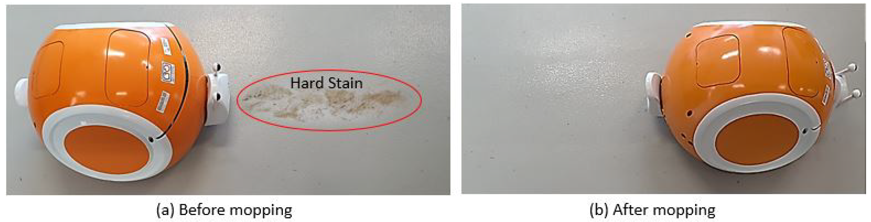
3.3. Cleaning Efficiency of Steam Mopping Robot

This section details the cleaning efficiency test of the steam mopping robot compared with a normal mopping robot by replacing the boiler-nozzle assembly of the Snail robot with a normal water-spraying unit. We mainly tested removing a hard stain and the wet floor drying time on a concrete floor. We tested removing two similar hard, stubborn stains: one with steam and the other with the normal water mopping robot at the same speed. The steam mopping robot needed two iterations, while the water mopping robot needed four rounds to completely remove the stain, as shown in Figure 12. Similarly, it was observed that after the Snail robot’s steam mopping, the wet surface dried within 1.5 min, whereas for the manual mopping with water, it took around six minutes for the surface to dry. Here, the superheated state of the condensed water helped to clean the hard stain and dry the floor quickly for the steam mopping robot. In addition, the steam mopping robot consumed 1 L. of water to mop a 5 m 2  area, whereas normal water mopping took around 3.5 L for the tested concrete floor. This shows that the steam mopping robot assured a green and hygienic environment, avoiding chemicals and killing harmful germs and bacteria while being less expensive, avoiding big water tanks, and being more productive for the cleaning industry.

4. Conclusions

An autonomous steam mopping robot design methodology was proposed and tested for eco-friendly cleaning and disinfection of typical indoor floors, such as tile, carpet, concrete, vinyl, sealed wood, and rugs. A low power-rated (2 bar, 1300 W) compact steam generation unit with twin nozzles and a 30 × 30 cm pad mopping unit was designed to balance lower energy consumption, attain a disinfection temperature, and increase the coverage area. The uniformity in steam dissipation across the mopping pad was validated using steam flow simulations and real-time tests, which assured the capability to maintain the disinfection temperature, set as 100  ° C. A novel motion controller design was developed and validated to compensate for extensive pad–floor friction disturbances, especially for rough floors such as carpet. The experimental results show the cleaning efficiency and productivity of the proposed robot, mainly in removing the hard stain, fast floor drying after mopping, and the consumption of little water. The experimental results ensure that the proposed steam mopping robot design is ideal for the disinfection of floors, especially in hospitals and eldercare centers, where disinfection is crucial.

Author Contributions

Conceptualization, S.P. and M.R.E.; methodology, S.P., M.M.R. and B.R.; software, V.S. and S.P.; validation, S.P. and V.S.; formal analysis, S.P., M.R.E. and Z.S.S.; investigation, S.P. and M.R.E.; resources, M.R.E.; data, S.P., V.S. and Z.S.S.; writing—original draft preparation, S.P., M.M.R., Z.S.S. and B.R.; supervision, M.R.E.; project administration, M.R.E.; funding acquisition, M.R.E. All authors have read and agreed to the published version of the manuscript.

Funding

This research was supported by the National Robotics Programme under its Robotics Enabling Capabilities and Technologies (Funding Agency Project No. 192 25 00051) and the National Robotics Programme under its Robotics Domain Specific (Funding Agency Project No. W1922d0110), administered by the Agency for Science, Technology and Research.

Acknowledgments

The authors would like to thank the National Robotics Programme, the Agency for Science, Technology and Research, and the SUTD for their support.

Conflicts of Interest

The authors declare no conflict of interest.

References

  1. Wordsworth, P.; Lee, R. Lee’s Building Maintenance Management; Blackwell Science: Princeton, NJ, USA, 2001. [Google Scholar]
  2. Ryu, B.H.; Cho, Y.; Cho, O.H.; Hong, S.I.; Kim, S.; Lee, S. Environmental contamination of SARS-CoV-2 during the COVID-19 outbreak in South Korea. Am. J. Infect. Control 2020, 48, 875–879. [Google Scholar] [CrossRef] [PubMed]
  3. Wolkoff, P.; Schneider, T.; Kildesø, J.; Degerth, R.; Jaroszewski, M.; Schunk, H. Risk in cleaning: Chemical and physical exposure. Sci. Total Environ. 1998, 215, 135–156. [Google Scholar] [CrossRef] [PubMed]
  4. Advanced Biotechnologies INC. Is UV Sterilisation Effective for Viruses and Bacteria? Available online: https://abionline.com/is-uv-sterilization-effective-for-viruses-and-bacteria (accessed on 14 May 2021).
  5. Houser, K.W. Ten Facts about UV Radiation and COVID-19; Taylor & Francis: Abingdon, UK, 2020. [Google Scholar]
  6. Wang, X.V.; Wang, L. A literature survey of the robotic technologies during the COVID-19 pandemic. J. Manuf. Syst. 2021, 60, 823–836. [Google Scholar] [CrossRef] [PubMed]
  7. Choi, H.K.; Cui, C.; Seok, H.; Bae, J.Y.; Jeon, J.H.; Lee, G.E.; Choi, W.S.; Park, M.S.; Park, D.W. Feasibility of ultraviolet light-emitting diode irradiation robot for terminal decontamination of coronavirus disease 2019 (COVID-19) patient rooms. Infect. Control. Hosp. Epidemiol. 2021, 43, 232–237. [Google Scholar] [CrossRef] [PubMed]
  8. Murphy, R.R.; Gandudi, V.B.M.; Adams, J. Applications of robots for COVID-19 response. arXiv 2020, arXiv:2008.06976. [Google Scholar]
  9. Song, L.; Wu, J.; Xi, C. Biofilms on environmental surfaces: Evaluation of the disinfection efficacy of a novel steam vapor system. Am. J. Infect. Control 2012, 40, 926–930. [Google Scholar] [CrossRef]
  10. Morrone, G.; De Lorenzi, S.; Barrai, I.; Mosca, B.; Finzi, G.; Cugini, P. Comparing different methods of sanitization. in operating theatres: Use of disinfectant detergents or of steam? In Proceedings of the 34th National Congress Anmdo, Catania, Italy, 18 September 2008. [Google Scholar]
  11. Bradbeer, S.J.; Coughlan, N.E.; Cuthbert, R.N.; Crane, K.; Dick, J.T.; Caffrey, J.M.; Lucy, F.E.; Renals, T.; Davis, E.; Warren, D.A.; et al. The effectiveness of disinfectant and steam exposure treatments to prevent the spread of the highly invasive killer shrimp, Dikerogammarus villosus. Sci. Rep. 2020, 10, 1–7. [Google Scholar] [CrossRef] [Green Version]
  12. Bayzi Corporation. Steam Cleaning Studies. Available online: https://bayzi.com/steam-cleaning-studies (accessed on 15 February 2021).
  13. Gillespie, E.; Williams, N.; Sloane, T.; Wright, L.; Kotsanas, D.; Stuart, R.L. Using microfiber and steam technology to improve cleaning outcomes in an intensive care unit. Am. J. Infect. Control 2015, 43, 177–179. [Google Scholar] [CrossRef]
  14. Abernethy, M.; Gillespie, E.; Snook, K.; Stuart, R.L. Microfiber and steam for environmental cleaning during an outbreak. Am. J. Infect. Control 2013, 41, 1134–1135. [Google Scholar] [CrossRef]
  15. Gillespie, E.; Wilson, J.; Lovegrove, A.; Scott, C.; Abernethy, M.; Kotsanas, D.; Stuart, R.L. Environment cleaning without chemicals in clinical settings. Am. J. Infect. Control 2013, 41, 461–463. [Google Scholar] [CrossRef]
  16. Colloff, M.; Taylor, C.; Merrett, T. The use ofdomestic steam cleaning for the control of house dust mites. Clin. Exp. Allergy 1995, 25, 1061–1066. [Google Scholar] [CrossRef] [PubMed]
  17. De Lorenzi, S.; Salvatorelli, G.; Finzi, G.; Cugini, P. Use of a steam generator for disinfection of hospital ward room surfaces. Br. Microbiol. Res. J. 2012, 2, 228. [Google Scholar] [CrossRef]
  18. Nilfisk, Ltd. Why Steam Is the Best Solution for Cleaning When Hygiene Is Critical. Available online: https://new.nilfisk.com/global/articles/steam-solution-when-hygiene-is-critical (accessed on 10 January 2021).
  19. Rosenzweig, M.; Ognjen, V. Steam Mop. US Patent 8,205,293, 26 June 2012. [Google Scholar]
  20. Shaw, R.R. Steam Mop. US Patent 6,584,990, 1 July 2003. [Google Scholar]
  21. kagoo.co.uk. Compare the Best Steam Cleaners. Available online: https://kagoo.co.uk/steam-cleaners (accessed on 10 January 2021).
  22. digitec.ch. Steam Cleaners. Available online: https://www.digitec.ch/en/s1/producttype/steam-cleaners-126 (accessed on 10 January 2021).
  23. Chan, J. The Best Affordable Robot Vacuums of 2021. Available online: https://www.reviewed.com/vacuums/best-right-now/best-affordable-robot-vacuums (accessed on 5 April 2021).
  24. Alex Colon, A.M. The Best Robot Mops for 2021. Available online: https://www.tomsguide.com/best-picks/best-robot-mops (accessed on 5 April 2021).
  25. LionsBot International Pte Ltd. LionsBot—Robots that Give Cleaners Superpowers. Available online: https://www.lionsbot.com/ (accessed on 15 August 2022).
  26. Global Robotics Platform. Global Robotics—Cleaning Robots. Available online: https://www.allrobotsin.com/cleaning-robots/ (accessed on 15 August 2022).
  27. Prabakaran, V.; Elara, M.R.; Pathmakumar, T.; Nansai, S. Floor cleaning robot with reconfigurable mechanism. Autom. Constr. 2018, 91, 155–165. [Google Scholar] [CrossRef]
  28. Tun, T.T.; Huang, L.; Mohan, R.E.; Matthew, S.G.H. Four-wheel steering and driving mechanism for a reconfigurable floor cleaning robot. Autom. Constr. 2019, 106, 102796. [Google Scholar] [CrossRef]
  29. Ilyas, M.; Yuyao, S.; Mohan, R.E.; Devarassu, M.; Kalimuthu, M. Design of sTetro: A modular, reconfigurable, and autonomous staircase cleaning robot. J. Sens. 2018, 2018, 8190802. [Google Scholar] [CrossRef]
  30. Ramalingam, B.; Elara Mohan, R.; Balakrishnan, S.; Elangovan, K.; Félix Gómez, B.; Pathmakumar, T.; Devarassu, M.; Mohan Rayaguru, M.; Baskar, C. sTetro-Deep Learning Powered Staircase Cleaning and Maintenance Reconfigurable Robot. Sensors 2021, 21, 6279. [Google Scholar] [CrossRef]
  31. Vega-Heredia, M.; Mohan, R.E.; Wen, T.Y.; Siti’Aisyah, J.; Vengadesh, A.; Ghanta, S.; Vinu, S. Design and modelling of a modular window cleaning robot. Autom. Constr. 2019, 103, 268–278. [Google Scholar] [CrossRef]
  32. Muthugala, M.; Vega-Heredia, M.; Mohan, R.E.; Vishaal, S.R. Design and control of a wall cleaning robot with adhesion-awareness. Symmetry 2020, 12, 122. [Google Scholar] [CrossRef] [Green Version]
  33. Sang, A.W.Y.; Moo, C.G.; Samarakoon, P.; Bhagya, S.; Muthugala, M.; Elara, M.R. Design of a Reconfigurable Wall Disinfection Robot. Sensors 2021, 21, 6096. [Google Scholar] [CrossRef]
  34. Ramalingam, B.; Yin, J.; Rajesh Elara, M.; Tamilselvam, Y.K.; Mohan Rayguru, M.; Muthugala, M.; Félix Gómez, B. A human support robot for the cleaning and maintenance of door handles using a deep-learning framework. Sensors 2020, 20, 3543. [Google Scholar] [CrossRef]
  35. Yin, J.; Apuroop, K.G.S.; Tamilselvam, Y.K.; Mohan, R.E.; Ramalingam, B.; Le, A.V. Table cleaning task by human support robot using deep learning technique. Sensors 2020, 20, 1698. [Google Scholar] [CrossRef] [PubMed] [Green Version]
  36. Griffith, C.; Moore, G. An evaluation of the cleaning properties of a microfibre cloth. Am. J. Infect. Control 2005, 33, e35–e36. [Google Scholar] [CrossRef]
  37. Wren, M.; Rollins, M.; Jeanes, A.; Hall, T.; Coen, P.; Gant, V. Removing bacteria from hospital surfaces: A laboratory comparison of ultramicrofibre and standard cloths. J. Hosp. Infect. 2008, 70, 265–271. [Google Scholar] [CrossRef] [PubMed]
Figure 1. Autonomous steam mopping and disinfection robot ‘Snail’.
Mathematics 11 01086 g001
Figure 2. Snail robot’s CAD mechanical design.
Mathematics 11 01086 g002
Figure 3. Steam generation and distribution process flow diagram.
Mathematics 11 01086 g003
Figure 4. Nozzle designs and proposed twin-nozzle assembly.
Mathematics 11 01086 g004
Figure 5. Mop temperature-monitoring and uniform floor contact system.
Mathematics 11 01086 g005
Figure 6. System architecture.
Mathematics 11 01086 g006
Figure 7. Differential drive mechanism.
Mathematics 11 01086 g007
Figure 8. Top view of simulated temperature distribution at the mop–cavity interface.
Mathematics 11 01086 g008
Figure 9. Rise in temperature at corners of pad–floor interface for various floors.
Mathematics 11 01086 g009
Figure 10. Snail robot’s traverse feedback before and after motion controller design.
Mathematics 11 01086 g010
Figure 11. Autonomous traverse test following trajectory with motion controller design.
Mathematics 11 01086 g011
Figure 12. Cleaning efficiency of Snail when a removing hard stain.
Mathematics 11 01086 g012
Table 1. RMS Path tracking error (m) comparison.
Floor SurfacePIDProposed
Concrete0.0210.015 (+34%)
Carpet0.0290.016 (+76%)
Disclaimer/Publisher’s Note: The statements, opinions and data contained in all publications are solely those of the individual author(s) and contributor(s) and not of MDPI and/or the editor(s). MDPI and/or the editor(s) disclaim responsibility for any injury to people or property resulting from any ideas, methods, instructions or products referred to in the content.

