Abstract
With high performances of image capturing tools, image information can be easily obtained by screenshots that make image copyright protection a challenging task. The existing screen-shooting watermarking algorithms suffer from a huge running time, in addition to their low robustness against different screenshot attacks, such as different distances and capturing angles of the screenshots. In this paper, a fast and robust high-capacity flexible watermarking algorithm for screenshot images is proposed. Firstly, Oriented FAST and Rotated BRIEF (ORB) feature points are extracted from the input image. Secondly, the feature points are then sorted in a descending order according to their response values. Then, the first five non-overlapping feature points are selected for the embedding by using Hamming window-based filtering method. Furthermore, we exploit the multi-resolution property of Discrete Wavelet Transform (DWT) and energy compaction property of Singular Value Decomposition (SVD) to embed the watermark. Therefore, the classical DWT combined with Singular Value Decomposition (SVD) are adopted to improve the robustness and capacity of the proposed watermarking algorithm. At the extraction side, the sum of the response values for the three RGB channels of the color-ripped image is calculated to improve the feature point localization accuracy. Experimental results show that the proposed screen-shooting watermarking algorithm improves running speed while ensuring the robustness. Furthermore, it has less time complexity and high robustness compared with the state-of-the-art watermarking algorithms against different screenshot attacks.
Keywords:
screen capture; screen-shooting watermarking; ORB feature points; DWT; SVD; hamming window; robust watermarking MSC:
68P27
1. Introduction
Recently, image capturing devices are more powerful, which make image copyright protection a crucial task and hence attracted many researchers’ attention. Generally, image watermarking algorithms can be divided into three categories: robust watermarking algorithms that can resist attacks; fragile watermarking algorithms that can detect whether an image has been tampered with; and semi-fragile watermarking algorithms that combine the previous two types of algorithms. In the literature, many classical robust watermarking algorithms have been presented [1,2,3,4,5,6,7,8]. Furthermore, watermarking information can be extracted accurately after the attacks by a screen capture model with lens distortion, light source distortion, and moiré distortion [9]. Consequently, the fast Screen-Shooting Resilient (SSR) watermarking algorithms have been introduced [10]. These algorithms first embed the watermarking information in a digital image and display it on a computer screen. Then, the image is captured with a camera. Additionally, watermarking information can be embedded in the spatial domain or frequency domain such as the Discrete Cosine Transformation (DCT), Discrete Fourier Transformation (DFT), Discrete Wavelet Transformation (DWT), etc. Recently, many watermarking algorithms have been presented in the frequency domain which are called frequency-domain watermarking algorithms [11]. The frequency-domain watermarking algorithms are more robust against many malicious attacks, but they require more processing time [10]. DWT captures an isotropic feature of the human visual system more accurately compared with DCT and DFT, which allows embedding the watermark in less sensitive areas with high robustness and no degradation in the image quality [12,13,14,15,16,17,18]. In this paper, we exploit the multi-resolution property of DWT and the energy compaction property of SVD to embed a watermark that is resistant to screenshot attacks [12].
A highly effective screen-shooting watermarking algorithm must have the following characteristics: excellent imperceptibility, low time complexity, strong robustness, and high adaptability to different camera devices [19]. To make the watermarking information invisible, the Peak Signal to Noise Ratio (PSNR) of the watermarked image should be higher than 40. Additionally, reducing time complexity of the algorithm can also improve the applicability of the algorithm. To this end, it is necessary to design an algorithm that can quickly find the location of the embedded watermark and extract the watermark information. Furthermore, it is ensured that any type of screen and camera-based algorithms can be applied to obtain the watermark sequence from a watermarked image in a camera using a watermarking extraction algorithm. Thus, the classical feature point algorithms and frequency domain watermarking algorithms are applied in screen-shooting-based watermarking, where the feature points detection algorithms can find the location of the embedded watermark information in the case of a screen-shooting attack. Moreover, the robustness of the frequency domain-based watermarking algorithm can further resist screenshot attacks. For feature points-based algorithms, Fang et al. [10] applied the traditional Scale Invariant Feature Transform (SIFT) feature point detection and description algorithm. Li et al. [11] applied the Superpoint algorithm based on a machine learning approach to accurately find out the feature points of the embedded watermark. For the frequency domain-based watermarking algorithm, Fang et al. [10] and Li et al. [11] used the Discrete Cosine Transform (DCT) and Quaternion Discrete Fourier Transform (QDFT), respectively. However, the feature point detectors used by these algorithms are relatively slow. Moreover, they used only one frequency domain transform to embed and extract the image watermark. In this paper, we propose a watermarking algorithm that combines the Oriented FAST and Rotated BRIEF (ORB) feature points with the dual frequency domain of Discrete Wavelet Transformation-Singular Value Decomposition (DWT-SVD). This consequently improves both running speed and robustness of the watermarking algorithm.
The main contributions of this paper can be summarized as follows:
- We apply the fast ORB feature point algorithm to find out the anti-screenshot feature points for embedding the watermark information. Then, in the watermarking extraction process, the ORB feature values of the three RGB color channels are calculated simultaneously.
- A DWT-SVD based dual frequency domain watermarking algorithm is adopted to embed watermark information in the frequency domain. This makes a notable improvement in the robustness of the proposed algorithm.
- The marker for embedding the watermark is designed by calculating the ORB feature point descriptors and the layout of the Aesthetic Quick Response (AQR) code to ensure that the watermark information can be extracted with low bit error rates.
- We conduct some extensive experiments under different screen-shooting attacks, such as different distances and capturing angles of the screenshots, which indicate that the proposed algorithm outperforms the existing algorithms in terms of robustness, capacity, and time complexity.
This paper is organized as follows: related works are presented in Section 2. Section 3 describes the embedding and extraction processes of the proposed watermarking algorithm, including the generation of watermark information, ORB keypoints, fast feature regions, the watermark template embedding module, watermark image design, and multi-channel features. Experimental results and analysis are then presented in Section 4. Finally, Section 5 concludes the paper and discusses some of the future work directions.
2. Related Works
2.1. ORB Feature Points-Based Algorithms
The localization of feature points is essential for protecting image copyright. It obtains the region in which the watermark sequence can be embedded accurately under different flipping conditions. An efficient feature point detection algorithm can find out the feature points with identical characteristics in different photographic scenes [20]. Fang et al. [10] employed SIFT for the screen-shooting watermarking algorithm. SIFT is a classic feature point algorithm [21], which has its own detector and descriptor. However, finding the SIFT feature points consumes a lot of time and causes a huge burden on the computing equipment. To solve this problem, Ruble et al. [22] proposed the ORB feature point detection algorithm. ORB is computationally efficient and highly noise resistant, and it can be used for applications requiring real-time performance than SIFT [22]. Many methods have been adopted to improve the effectiveness of the ORB feature points matching [23,24,25,26,27,28,29]. Ma et al. [23] replaced the descriptor with Learned Arrangements of Three Patch Codes (LATCH) and Local Binary Pattern (LBP) descriptors. Then, they calculated these two descriptors separately using the pixel blocks around the feature points. Finally, the two descriptors were combined to generate a 384-bit sequence descriptor to describe the feature points. Wang et al. [24] proposed the GA-ORB algorithm based on the application of ORB feature points to multispectral images in the field of geometric algebra. Qin et al. [25] improved the robustness of the ORB algorithm by first finding feature points in the space with scale-invariance, and then they calculated the Hamming distance to match feature points. Their method improved the matching accuracy by 68.27%. Weberruss et al. [26] applied the Harris-Stephens corner point detector to detect corner points at different scales and obtained a First Input First Output (FIFO) queue for all the obtained feature points. Their method was used for the Simultaneous Localization and Mapping (SLAM) system in robots. Since the robot needs to complete both feature point localization and map building steps at the same time as it moves through a scene, the algorithm should have a high feature point localization speed. Thus, Mur-Artal et al. [27] combined ORB feature points with SLAM systems and proposed the monocular ORB-SLAM algorithm. Furthermore, they proposed the ORB-SLAM2 algorithm [28] and ORB-SLAM3 [29] algorithms for monocular, stereo, and RGB-D cameras. The ORB algorithm can be applied to various applications, such as image classification, robot pathfinding, and scene modeling. In this paper, we use the ORB algorithm for screen photography watermarking algorithms.
2.2. Screen-Shooting Watermarking-Based Algorithms
Screen-shooting watermarking means that if a watermarked image is displayed on a screen and the screen is then captured by a device camera, the embedded watermark can be extracted from the captured image. The existing robust image watermarking algorithms do not have excellent performance for screenshot images [30,31,32]. During screen capturing of watermarked images, the image and watermark are subject to a series of strong attacks [33], so watermarking algorithms need to resist optical distortion, lens distortion, and disturbance occurring during the capturing process [34]. In robust watermarking algorithms, embedding the watermark information in the frequency domain generated by the transformation often improves both the imperceptibility and robustness of the algorithm.
Fang et al. [10] applied a DCT decomposition of the original image and embedded the watermark information into the AC coefficients to resist the effects of the screen-shooting. Furthermore, Fang et al. [35] proposed to add Gaussian white noise with a variance of 0.001 after embedding the watermark using the DCT transform, which made the watermark template more random. To ensure that the watermarking information can be extracted intact even when the image is only partially acquired, they flipped the watermark stencil so that a larger, about-centered symmetric watermark stencil was created. Due to the robustness of the flip-based stencil approach for screen-shooting watermarking algorithms, Fang et al. [36] adopted it to embed Gaussian noise with a mean of 0 and variance of 0.01 into the red channel of the image. Furthermore, they used a novel watermark stencil to embed the watermark information directly into the blue channel. This ensures that more energy is concentrated in the low-frequency space in the Fourier domain. Additionally, this algorithm exploited U-Net [37] to enhance the features of the watermark stencil in the extraction of the watermark, and to design a simple classification network to train the correspondence between the watermark-containing image blocks and the watermark information. Moreover, Fang et al. [19] proposed a more robust watermarking template and added attention and regression subnets to improve the performance of the watermarking algorithm. Chen et al. [38] applied the Discrete Fourier Transform (DFT) to a screen photography watermarking algorithm and developed a Local Square Feature Region (LSFR) method. Furthermore, Chen et al. [39] proposed a method which divides the satellite image into a synchronous region and a message region, and then they embedded the watermarking information in both regions using the DFT. Furthermore, Chen et al. [40] used Quick Response (QR) coding combined with inverse DFT to embed the watermark sequence into the DFT domain. This provides the watermark with error correction capability while increasing the watermark capacity. Other researchers also generated watermark sequences based on the image itself and then applied a circular template to determine the size of the circular grey value based on the watermark bits [41]. Zhu et al. [42] developed a framework that simulates the screen photography process by using a neural network. Primila et al. [43] referenced the full image during pre-processing, which made the algorithm inoperable and more robust against different attacks.
3. Proposed Algorithm
The proposed algorithm embeds and extracts watermark information in the frequency domain of DWT-SVD. The steps of the proposed screen-shooting watermarking algorithm are fully presented in the following subsections:
3.1. Watermark Embedding
Firstly, the input color image in RGB color space is converted to YCbCr color space, and the Y channel of the image is selected to find the feature points. Then, all the feature points are detected using the ORB keypoints detector. The feature points are then sorted in a descending order according to their response value. After that, the first five non-overlapping feature points are selected by using the Hamming window-based filtering method. Finally, the DCT template method [10] is adopted to embed the watermark in a more suitable location. The flow diagram of the proposed watermark embedding process is shown in Figure 1.
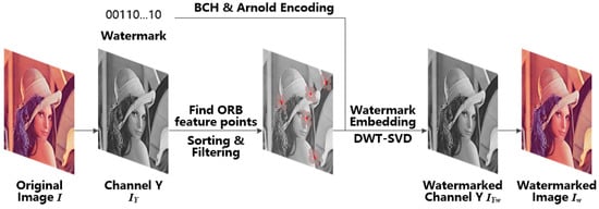
Figure 1.
Watermark embedding architecture.
3.1.1. Generating Watermark Information
Generally, the initial information of the watermark is a combination of decimal numbers. To accommodate the embedding and extraction algorithms, the watermark information needs to be converted into binary digits (0,1). Then, the binary form of the watermark is encoded by the Bose Chaudhuri Hocquenghem (BCH) algorithm [44] into a 0,1 sequence with a length close to or equal to bits. The BCH algorithm expands a one-dimensional watermark sequence into a two-dimensional matrix of size . To ensure that the length of this sequence is exactly equal to , the missing watermark bits are filled with 0. This means that the watermark matrix size and the length of the watermark sequence after conversion should satisfy the relationship: . Finally, an Arnold encoding algorithm is used to permute the watermark information without modifying the matrix dimensions. After getting Arnold’s permutation, the watermark matrix is copied and expanded into a large watermark matrix of size . To maximize the watermarking capacity, the difference between and should be minimized, as shown in the following Equation (1):
Figure 2 illustrates the process of generating a watermark matrix. The watermark matrix has a total of bits that need to be filled with 0. This is related to the original length of the watermark sequence and the length of the BCH encoder’s error correction length. In this paper, we set , , , and the size of the final watermark matrix is 256 × 256. The parameters , , and need to be saved and transferred to the decoding side when the watermarking information is extracted. The size of the watermark embedding area is chosen to prevent the interference situation where multiple embedding areas may overlap with each other.
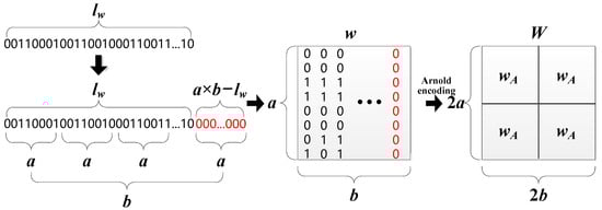
Figure 2.
The main steps for generating a watermark matrix. Red color bits indicate the added bits.
3.1.2. ORB Feature Point Detection
Rublee et al. [22] proposed the ORB feature point algorithm with excellent efficiency and performance for feature point matching. The ORB algorithm mainly consists of two main parts: the oFAST detection algorithm that can detect feature points, and the rBrief description algorithm that can generate features for each feature point.
- oFAST feature points detector
The All pixels in the Y channel of an input image are first traversed through a raster scan. For each pixel , a circle with a radius of 3 pixels is drawn at its center. For all the 16 pixels on the circle, the absolute value of the gray value difference between consecutive multiple pixels and the point’s gray value is calculated. Then, the point is determined as a feature point. To speed up the detection of feature points, we employ Rublee et al. [22] to improve the speed of the feature points detection.
- rBrief descriptor
In this paper, we adopt Ma et al.’s method [45] to select the location of the pixel points and the number of times the pixel points are applied. For each oFAST feature point, 256 pairs of pixel points are selected within a 26 × 26 window. These pairs of pixel points are divided equally into 32 groups, and each group has 8 pairs of pixel points. Each pair of pixel points can generate a bit—0 or 1. The final rBrief descriptor contains 32 integers greater than or equal to 0, and less than or equal to 255. The process is shown in Figure 3.
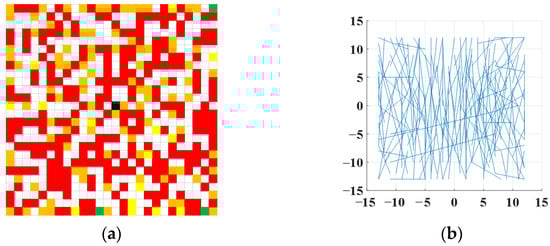
Figure 3.
The selected number and position of rBrief pixels. (a) Number of pixel pair selection; (b) The position of the pixel pair selection.
3.1.3. Selection of Watermark Embedding Area
Fang et al. [10] applied the SIFT algorithm to detect feature points. However, all pixels in the embedding region were embedded with watermark information except for the pixels in the rows and columns where the feature points were located. This approach affected the accuracy of the SIFT feature value calculation. Meanwhile, each bit of the watermark requires a block of 8 × 8 pixels, resulting in a small capacity of the watermark. In this paper, each bit of the watermark requires a 4 × 4 region for embedding. When 4-bit watermarks are set as a group, each group needs 8 × 8 pixels. Since the ORB feature point response values in Ma et al. [45] require a 26 × 26 patch during the calculation, the pixel values in this part cannot be modified when designing the feature regions. Additionally, we proposed to use the Aesthetic Quick Response (AQR) code [46] to resist screenshot attacks. AQR requires that the watermark embedding region to include the original region located at the centre and the watermark region located around it, and their ratio is close to 1:2. Therefore, we design the feature region of the embedded watermark by combining Ma et al.’s method [45] and Liu et al.’s method [46], as shown in Figure 4. Each feature point needs a 74 × 74 area for embedding the watermark. Moreover, for all the feature points embedded in the watermark, the 74 × 74 area centered on the points cannot overlap. To this end, this paper investigates an algorithm for fast screening of non-overlapping feature regions based on the Hamming window [46].
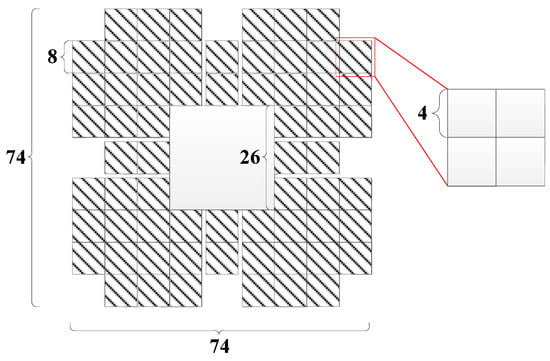
Figure 4.
Marker area with embedded watermark.
Each feature point is compared with all previously selected feature points to confirm that their feature regions are not overlapped. However, the time complexity of this comparison is . To record the selected feature points quickly, a zero matrix with the same size as the image needs to be declared as a marker matrix. After calculating response values of the ORB feature points for all pixels in the Y channel of the image, the point of the matrix , which is located at the same position as the ORB feature point, is checked in a descending order. If the maximum value centered on of the 74 × 74 Hamming window is 0, the corresponding ORB feature point is selected to embed the watermark, and the other values of the corresponding Hamming window in are all modified to 1. Otherwise, the next ORB feature point is selected and then the previous step is repeated. Table 1 shows an example of the whole process with a 3 × 3 Hamming window. In Table 1, ORB Response values are applied to choose the adaptive ORB feature points.

Table 1.
Applying the Hamming window to filter out non-overlapping feature regions.
In summary, two types of feature points are filtered out: (1) the feature points with a distance less than half the distance from the edge of the image to the edge of the window; (2) the feature points with horizontal/vertical distance from the previously selected feature points less than the edge length of the window. In order to make the algorithm more convenient to solve the problem and accurately select the embedding region, these two feature points need to be filtered out, and it can be represented by the following Equation (2).
where and are the horizontal and vertical coordinates of the i-th feature point; and are the edge lengths of the image and the Hamming window, respectively; is the angle between the line of the i-th and (i − 1)-th feature points and the horizontal direction. Fang et al. [19] compared each feature point with all previously selected feature points with a time complexity of . The proposed algorithm sets up a zero matrix as a medium and then adopts the Hamming window extremum method to reduce the time complexity to .
3.1.4. Watermark Template Embedding
Dual transform watermarking algorithms based on DWT and SVD have attracted much attention in recent years [47]. In the literature, the combination of DWT and SVD improved the robustness of image watermarking algorithms [47,48,49]. This kind of algorithm can improve the robustness while increasing the imperceptibility of the watermark. In this paper, we exploit the multi-resolution property of DWT, and the energy compaction property of SVD to embed a watermark that is resistant to screenshot attacks [12]. Specifically, each 4 × 4 pixel block is first decomposed by DWT, and then 4 sub-bands are generated, including a low-frequency sub-band LL and 3 high-frequency sub-bands—HL, LH, and HH. Since the low-frequency sub-band includes the main components of the image information, the watermark information is embedded in the LL sub-band, which has excellent robustness. Therefore, the “db3” filter is used to allow smooth SVD decomposition and embedding of the watermark. The low-frequency sub-band LL can be expressed as:
where is a scaling function, which can be shown as in Equation (4):
where is the scale of transform decomposition; and are the length and width of the decomposed image, respectively. Next, SVD decomposition is performed on the low-frequency sub-band LL. The decomposition process can be expressed as in Equation (5) as follows:
where and are two orthogonal matrices; is a diagonal matrix containing singular values that are arranged in a descending order. Thakur et al. [49] analyzed three matrices and found that the two coefficients in the first column of the matrix can resist JPEG compression. The fact that JPEG compression is a significant part of the screen-shooting process provides a strong rationale for migrating SVD to the screenshot watermarking algorithm. Figure 5 shows the whole process for watermark embedding.
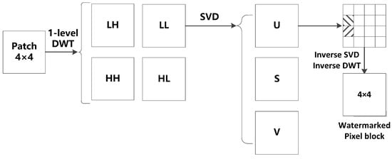
Figure 5.
The DWT-SVD embedding watermark process.
Chang et al. [50] proved that the difference between the coefficients located in (2,1) and (3,1) (the first column of the second row, and the first column of the third row) in the matrix can resist the JPEG compression attack. In the proposed algorithm, the larger coefficient is placed at (2,1), and the smaller coefficient is placed at (3,1). Since there are many uncontrollable influences during screen capturing, the difference between the two coefficients needs to be scaled up. Here, it can be adjusted by an embedding strength , which allows the coefficients and to better satisfy Equation (6) as follows:
where is the i-th watermark information. During the generation of the watermark stencil by the embedding method, if a “0” is embedded, the pixels corresponding to the top half of the matrix will be lighter; otherwise, these pixels will be darker. Figure 6 illustrates the embedding template for the watermark.
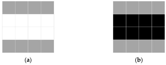
Figure 6.
The embedded template of the watermark: (a) Watermark bit “1”; (b) Watermark bit “0”.
After modifying the coefficients of the matrix, we perform inverse SVD and inverse DWT processes, respectively, to convert the image back to the spatial domain. After the embedding process of a feature region is completed, the remaining feature regions are processed in the same way. Finally, the Y channel component , containing the watermark information, is combined with the Cb and Cr channels to obtain the watermarked image .
3.2. Watermark Extraction
Once the watermarked image is displayed on the screen, it is captured by the phone camera. To obtain the copyright information, watermark extraction needs to be performed. The watermark extraction process is shown in Figure 7. Firstly, the captured watermarked image is pre-processed by applying geometric correction and then applying the Wiener filter. The Wiener filter is applied to reduce screen-shooting noise and remove blurring from the captured watermarked image for further processing. Secondly, the watermarked image is divided into three channels—R, G, and B—and then the response values of ORB feature points are calculated for all the pixels in each channel. Then, the response values of each pixel in the three channels are summed and then sorted in a descending order. The first few ORB feature points with the largest response values and without overlapping feature regions are selected. The resulting number of feature points at this stage is three times higher than that of the watermark embedding process. Next, the watermarked sequences within each feature region are extracted, and the best watermarked sequence is selected by voting. Finally, the final watermark information is obtained by using BCH and Arnold decoding. The following subsections describe each step in detail.
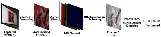
Figure 7.
The watermark extraction steps.
3.2.1. Pre-Processing of Captured Watermarked Image
During the process of capturing the watermarked image which was displayed on the screen, the image could change in position, size, angle, etc. Therefore, the captured image needs to be corrected to achieve an overall positioning of the image. Equation (7) is used for correction as follows:
where and are the coordinates of the pixels in the same position of the corrected image and the captured image , respectively. is a matrix with a correction function. Because the matrix has eight Degrees of Freedom (DOF), the positions of the four points of an image need to be determined before it can be applied.
Usually, the four endpoints of an image can be applied for image detection and geometric correction. To accurately determine the positions of these four endpoints, a black box is added around the watermarked image . During pre-processing of the watermarked image, the edges of the black box can be easily detected by the edge detection algorithm. Then, the positions of the four endpoints of the black box can be determined so that the four endpoints of the image are geometrically corrected. The corrected image has the same dimension as the watermarked image . Since the ORB feature points are found on the noise-free image before the watermark is embedded, the correction image needs to be denoised. Among the denoising methods, we apply the Wiener filtering to predict the original image due to its extremely small Mean Square Error (MSE) [51,52].
where and are the mean and variance of the current window, respectively. It satisfies the following equations:
where is a sliding window of the filtering function, and its size is . is the size of the corrected image .
3.2.2. Multi-Channel Feature Point Positioning
The watermarked image generated by the proposed algorithm could be attacked by the screenshot, which affects the Y, Cb, and Cr channels. Therefore, to extract the watermark, the sum of the feature points response values of all channels needs to be calculated. That is, it is not necessary to convert the corrected image into the YCbCr color space.
Then, the feature points are sorted in a descending order according to the total response value , and the method presented in Section 3.1.3 is adopted so that the feature regions of the feature points are not overlapped. The screen capturing process affects the feature points in two main aspects as follows:
- (a)
- The intensity of the feature points: In this case, the response values of the feature points will be changed, which affects their arrangement order. Thus, the number of feature points to be extracted is increased. For -ORB feature points used for watermark embedding, feature points are extracted during the watermark extraction. Furthermore, the size of the Hamming window is changed from 74 × 74 to 40 × 40 to prevent the feature points in the embedded watermark from being ignored due to the changes in response values.
- (b)
- The position of the feature points: In this case, the position of each feature point will be slightly offset. Considering the uncertainty of the offset direction, the feature point may move to the surrounding 8 pixels. So, the watermark information must be extracted for the 3 × 3 pixels centered on the feature point. Then, 9 watermark sequences are extracted for each feature point, and the total number of watermark sequences is . Consequently, a total of watermark sequences are extracted from the entire image.
3.2.3. Extracting Watermark Information
Firstly, each 8 × 8 pixel block in the feature area is decomposed by DWT. Then, SVD decomposition is used for the low-frequency sub-band LL, and and of the component are obtained. The equation for extracting the watermark for each feature point is as follows:
The 9 sequences extracted from each feature point constitute a group. Then, the watermark can be expressed as , where is the number of the watermark group. For each two watermark groups and for different feature points, select watermark sequences and to compare their similarities. The watermark pair whose difference is less than a threshold will be recorded. The specific process is shown in Equations (15) and (16):
where represents the XOR operation. The threshold is used to determine the correctness of watermark extraction. Then, the watermark group after stages is expressed as follows:
where is the number of recorded watermark pairs, and are the two watermark sequences included in the watermark pair . Finally, the extraction of the watermark can be done as shown in Equation (18) as follows:
In the process of the screen-shooting, there may be a small amount of bit error in the watermark sequence, but they are still similar to the original watermark , since the watermark groups for each ORB feature point are almost the same. For incorrect ORB feature points, their watermark sequences are very different from all the other feature points. Thus, although only of the watermark sequences are correct, the correct watermark sequence can still be obtained. The final watermark is obtained by Arnold decoding .
4. Experimental Results and Analysis
4.1. Implementation Details
In our experiments, we set and . The error correction code (ECC) used in the watermark sequence is BCH (256,156), which can correct 16-bit errors. If the number of error bits is less than 16, the watermark sequence can be successfully corrected. The allowed coded message bits are 256 bits. The color images “Lena”, “Mandril”, “Boats”, and “Peppers” are used to embed the watermarking information. The watermarked images are shown in Figure 8. In the experiments, the proposed algorithm had been applied on color images. However, grayscale images can also be considered by converting the color images into its grayscale version before extracting watermarking information. The monitor used in the experiment is “HP-N246v”, and the mobile phone used is “Honor V10”. The equipment and conditions of the screen-shooting experiment are shown in Figure 9.
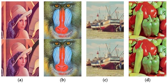
Figure 8.
The original images and the corresponding watermarked images by using the proposed embedding algorithm: The first row shows the original images, and the second row shows the corresponding watermarked images, respectively. (a) Lena. (b) Mandril. (c) Boats. (d) Peppers.
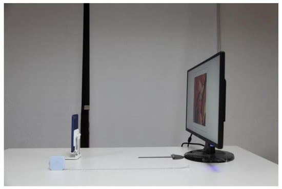
Figure 9.
Experimental equipment for the screenshot process.
4.2. k-Feature Points Embedding Regions
At least one pair of the feature points is required in the process of extracting the watermark. Consequently, the number of feature point regions should satisfy . In the experiments, we selected color images from the USC-SIPI image dataset [53] for . The distance between the mobile phone and monitor was set to 85 cm. The relationship between the Peak Signal-to-noise Ratio (PSNR) and is shown in Figure 10a, and the relationship between the Bit Error Rate (BER) of the extracted watermark and is shown in Figure 10b. In general, the watermarked image has a good imperceptibility, if PSNR was greater than 42. The PSNR and BER are decreasing with the increase in the number of the embedding regions . The results illustrated that the best performance can be achieved when the number of the embedding regions is equal to 5 ().
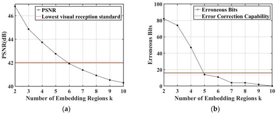
Figure 10.
The effect of different numbers of embedded regions k: (a) PSNR with different numbers of embedding regions; (b) BERs with different numbers of embedding regions.
4.3. Watermark Pair Matching Threshold (th)
If we accurately locate the correct feature points in the watermark extraction step, the difference between the watermark pairs will be small. This difference is defined as a threshold (). Furthermore, we extract ORB feature points from 1000 randomly selected images from BOSSbase ver1.01 database [54]. Then, we calculate the minimum difference (MD) of the watermark pair for each screenshot image as shown in Equation (19):
All images firstly use precisely located 2k-ORB feature points, and then use random 2k-ORB feature points. Then, the distribution function is determined by observing the matching difference between the watermark pairs obtained by these two sets of feature points. Figure 11a shows the minimum difference values and fitting curves when the screen-shooting distance is 55 cm.
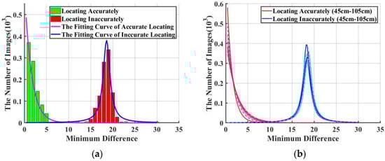
Figure 11.
Minimum Difference (MD) value distributions and fitting curves: (a) The MD value and fitting curve when the shooting distance is 55 cm; (b) The fitting curves when the screen-shooting distance is 45~105 cm. For each distance from 45 cm to 105 cm with step of 10 cm, we use different styles of lines with colors that are closed to Red color to represent “Locating Accurately”, and different styles of lines with colors that are closed to Blue color to represent “Locating Inaccurately”.
We can observe that the precise MD conforms to the exponential distribution, whereas the random MD conforms to the Gaussian distribution. Moreover, we set two hypotheses and that represent accurate positioning and unprepared positioning, respectively.
Based on the Neyman-Pearson (NP) method, the two hypotheses and can be defined as follows:
where is a threshold which can distinguish between the two hypotheses, and is a function of , which can be determined by Equations (20) and (21). can determine whether the MD of the current watermark pair conforms to the exponential distribution of or the Gaussian distribution of . In other words, we need to obtain an accurate threshold () to determine whether the ORB feature points are accurately located. Therefore, we define a false alarm probability as follows:
We set as adopted by Fang et al. [10] and combine the parameters of the fitted curve to get the value of . The of different shooting distances are shown in Table 2.
Table 2.
Threshold th at different screen-shooting distances.
To ensure that the watermark information can be extracted at any screen-shooting distance, we experimentally set th to 6.
4.4. Robustness Comparison
The color images used for the comparison experiments are selected from the USC-SIPI image database [53]. To evaluate the performance of the proposed watermarking algorithm, we used the peak signal-to-noise ratio (PSNR) and Bit Error Rate (BER). We compared the proposed watermarking algorithm with three different advanced watermarking algorithms—i.e., Pramila et al. [43], Fang et al. [10], Chen et al. [39] and Sahu et al. [55]. For a fair comparison with the other algorithms, the PSNR of the watermarked images was controlled to be slightly greater than 42. Table 3 shows the watermarked images from different algorithms compared with the proposed algorithm in terms of robustness during screen-shooting.
Table 3.
Performance evaluation results of the proposed watermarked images against different algorithms.
4.4.1. Robustness against Different Distances of Screenshots
In this experiment, we evaluated the performance of the proposed watermarking algorithm against different distances from the screen. Table 4 shows some of the captured and corrected images at different shooting distances for screen-shooting. Moreover, Table 5 lists the BER values for the proposed algorithm compared with Pramila et al. [43], Fang et al. [10], Chen et al. [39], and Sahu et al. [55] at different distances, from 45 cm to 105 cm. Figure 12a shows that the proposed watermarking algorithm had a better robustness compared with the other algorithms at all the screenshot distances used.
Table 4.
Captured and corrected images at different capturing distances.
Table 5.
BER values for the extracted watermark at different capturing distances.
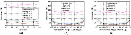
Figure 12.
Comparison of BER values at different distances and angles with Fang et al. [10], Chen et al. [39], Pramila et al. [43], and Sahu et al. [55]: (a) BER values at different distances; (b) BER values at different horizontal angles; (c) BER values at different vertical angles.
4.4.2. Robustness against Different Horizontal Angles of Screenshots
In this experiment, we evaluated the performance of the proposed algorithm against different horizontal angles of the screenshots. Table 6 shows some the captured and corrected images at different horizontal angles. Furthermore, Table 7 lists the BER values for the proposed algorithm compared with Pramila et al. [43], Fang et al. [10], Chen et al. [39], and Sahu et al. [55] with different horizontal angles, from left 65° to right 65°, with a capturing distance of 60 cm from the screen. Figure 12b shows a line graph to better indicate the performance of this experiment visually. As shown in Figure 12b, the proposed algorithm has an excellent robustness compared with other algorithms at all horizontal angles.
Table 6.
Captured and corrected images at different horizontal angles.
Table 7.
BER values for the extracted watermark at different horizontal angles.
4.4.3. Robustness against Different Vertical Angles of Screenshots
In this experiment, the images were rotated clockwise 90° to evaluate the performance of the proposed algorithm against different vertical angles of the screenshots; so, the different vertical angles would make it difficult for capturing. Table 8 shows some of the captured and corrected images at different vertical angles. Furthermore, Table 9 lists the BER values for each algorithm at different vertical angles with 60 cm distance far from the screen. From Figure 12c, we can conclude that all algorithms allow the shooting angle to be between 30° (Down) and 45° (up). The BER values of the proposed algorithm were all at least 6 bits lower than the comparing algorithms.
Table 8.
Captured and corrected images at different vertical angles.
Table 9.
BER values for the extracted watermark at different vertical angles.
From the above-mentioned comparison results, it can be demonstrated that our proposed watermarking algorithm has an excellent robustness against different screens-shooting attacks compared with the state-of-the-art watermarking algorithms.
4.5. Watermark Extraction Time
The proposed watermarking algorithm and Fang et al. [10] are feature point-based watermarking algorithms. Therefore, we compared the watermark extraction time of the proposed algorithm with Fang et al. [10]. Table 10, Table 11 and Table 12 show the watermark extraction time of the proposed algorithm compared with Fang et al. [10] at different shooting distances, different horizontal angles, and different vertical angles, respectively, with over 20 screenshot experiments. From Figure 13, we can conclude that the watermark extraction time of our proposed algorithm was always lower than that of Fang et al. [10].
Table 10.
Watermark extraction time at different distances from the screen.
Table 11.
Watermark extraction time at different horizontal angles.
Table 12.
Watermark extraction time at different vertical angles.
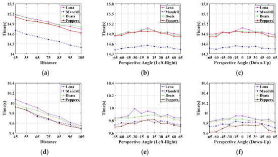
Figure 13.
Comparison of the watermark extraction time at different capturing distances and angles: (a–c) Watermark extraction time of Fang et al. [10] with different capturing distances, different horizontal angles, and different vertical angles, respectively; (d–f) Watermark extraction time of the proposed algorithm with different capturing distances, different horizontal angles, and different vertical angles, respectively.
5. Conclusions and Future Work
In this paper, a fast screen-shooting watermarking algorithm was proposed. Firstly, the input RGB color image was converted to YCbCr color space, and the Y channel of the image was selected to find the feature points. Then, the ORB keypoints detection algorithm was adopted to improve the accuracy and speed of feature points localization. Furthermore, a feature point ranking method based on the sum of the response values of the three RGB channels was adopted to prevent the impact of the screen capture process on the luminance of the watermarked image. Besides, a fast feature region screening method based on the marker was adopted to improve the watermarking capacity of the watermarking algorithm, while reducing the time complexity of feature region screening from to . Experimental results showed that the proposed algorithm outperforms the existing algorithms in terms of robustness against different attacks, capacity, and time complexity. In future work, the combination of deep learning methods will be investigated. Additionally, more effective algorithms will be used to achieve fast geometric correction of the watermarked images in complex environments. Moreover, the proposed watermarking algorithm is not robust enough for tamper detection or localization, due to the screen-shooting process which affects the image. However, the accuracy of the ORB keypoint detector algorithm, in terms of localization, may help in determining whether a location of an image has been tampered or not, based on the locations of the detected feature points. So, in the future we will try to improve the performance of the proposed algorithm for tamper detection and localization.
Author Contributions
Conceptualization, L.L., S.Z. and J.L.; Data curation, Y.B., S.Z. and M.E.; Formal analysis, Y.B., S.Z., J.L. and M.E.; Investigation, Y.B., S.Z., J.L. and M.E.; Methodology, Y.B., L.L. and S.Z.; Project administration, L.L. and S.Z.; Resources, L.L., S.Z. and J.L.; Software, Y.B. and S.Z.; Supervision, L.L.; Validation, Y.B., S.Z., J.L. and M.E.; Visualization, Y.B., L.L., S.Z., J.L. and M.E.; Writing—original draft, Y.B., S.Z., J.L. and M.E.; Writing—review & editing, Y.B., L.L., S.Z. and M.E. All authors have read and agreed to the published version of the manuscript.
Funding
This research was funded by the National Natural Science Foundation of China (Grant No. 62172132).
Data Availability Statement
The data are available upon a request to the corresponding author.
Acknowledgments
The authors would like to thank all anonymous reviewers for their helpful comments and suggestions.
Conflicts of Interest
The authors declare no conflict of interest.
References
- Chen, Z.; Li, L.; Peng, H.; Liu, Y.; Yang, Y. A novel digital watermarking based on general non-negative matrix factorization. IEEE Trans. Multimed. 2018, 20, 1973–1986. [Google Scholar] [CrossRef]
- Hua, G.; Zhao, L.; Zhang, H.; Bi, G.; Xiang, Y. Random matching pursuit for image watermarking. IEEE Trans. Circuits Syst. Video Technol. 2018, 29, 625–639. [Google Scholar] [CrossRef]
- Liu, X.L.; Lin, C.C.; Yuan, S.M. Blind dual watermarking for color images’ authentication and copyright protection. IEEE Trans. Circuits Syst. Video Technol. 2016, 28, 1047–1055. [Google Scholar] [CrossRef]
- Zong, T.; Xiang, Y.; Natgunanathan, I.; Guo, S.; Zhou, W.; Beliakov, G. Robust histogram shape-based method for image watermarking. IEEE Trans. Circuits Syst. Video Technol. 2014, 25, 717–729. [Google Scholar] [CrossRef]
- Asikuzzaman, M.; Pickering, M.R. An overview of digital video watermarking. IEEE Trans. Circuits Syst. Video Technol. 2017, 28, 2131–2153. [Google Scholar] [CrossRef]
- Kang, X.; Yang, R.; Huang, J. Geometric invariant audio watermarking based on an lcm feature. IEEE Trans. Multimed. 2011, 13, 181–190. [Google Scholar] [CrossRef]
- Huang, Y.; Niu, B.; Guan, H.; Zhang, S. Enhancing image watermarking with adaptive embedding parameter and psnr guarantee. IEEE Trans. Multimed. 2019, 21, 2447–2460. [Google Scholar] [CrossRef]
- Zhong, X.; Huang, P.; Mastorakis, S.; Shih, F.Y. An automated and robust image watermarking scheme based on deep neural networks. IEEE Trans. Multimed. 2020, 23, 1951–1961. [Google Scholar] [CrossRef]
- Schaber, P.; Kopf, S.; Wetzel, S.; Ballast, T.; Wesch, C.; Effelsberg, W. CamMark: Analyzing, modeling, and simulating artifacts in camcorder copies. ACM Trans. Multimed. Comput. Commun. Appl. 2015, 11, 1–23. [Google Scholar] [CrossRef]
- Fang, H.; Zhang, W.M.; Zhou, H.; Cui, H.; Yu, N.H. Screen-shooting resilient watermarking. IEEE Trans. Inf. Secur. 2019, 14, 1403–1418. [Google Scholar] [CrossRef]
- Li, L.; Bai, R.; Zhang, S.; Chang, C.C.; Shi, M. Screen-Shooting Resilient Watermarking Scheme via Learned Invariant Keypoints and QT. Sensors 2021, 21, 6554. [Google Scholar] [CrossRef]
- Mallat, S.G. A theory for multiresolution signal decomposition: The wavelet representation. IEEE Trans. Pattern Anal. Mach. Intell. 1989, 11, 674–693. [Google Scholar] [CrossRef]
- Guariglia, E.; Silvestrov, S. Fractional-Wavelet Analysis of Positive definite Distributions and Wavelets on D′(C). In Engineering Mathematics II. Springer Proceedings in Mathematics & Statistics; Silvestrov, S., Rančić, M., Eds.; Springer: Cham, Switzerland, 2016; Volume 179, pp. 337–353. [Google Scholar] [CrossRef]
- Yang, L.; Su, H.; Zhong, C.; Meng, Z.; Luo, H.; Li, X.; Tang, Y.Y.; Lu, Y. Hyperspectral image classification using wavelet transform-based smooth ordering. Int. J. Wavelets Multiresolut. Inf. Process. 2019, 17, 1950050. [Google Scholar] [CrossRef]
- Guariglia, E. Harmonic Sierpinski Gasket and Applications. Entropy 2018, 20, 714. [Google Scholar] [CrossRef] [PubMed]
- Zheng, X.; Tang, Y.Y.; Zhou, J. A Framework of Adaptive Multiscale Wavelet Decomposition for Signals on Undirected Graphs. IEEE Trans. Signal Process. 2019, 67, 1696–1711. [Google Scholar] [CrossRef]
- Guariglia, E. Primality, Fractality, and Image Analysis. Entropy 2019, 21, 304. [Google Scholar] [CrossRef]
- Berry, M.V.; Lewis, Z.V. On the Weierstrass-Mandelbrot fractal function. Proc. R. Soc. Lond. Ser. A Math. Phys. Sci. 1980, 370, 459–484. [Google Scholar]
- Fang, H.; Chen, D.D.; Wang, F.; Ma, Z.H.; Liu, H.G.; Zhou, W.B.; Zhang, W.M.; Yu, N.H. TERA: Screen-to-Camera image code with transparency, efficiency, robustness and adaptability. IEEE Trans. Multimed. 2021, 24, 955–967. [Google Scholar] [CrossRef]
- Zhu, Q.; Wang, Z.; Hu, H.; Xie, L.F.; Ge, X.M.; Zhang, Y.T. Leveraging photogrammetric mesh models for aerial-ground feature point matching toward integrated 3D reconstruction. ISPRS J. Photogramm. Remote Sens. 2020, 166, 26–40. [Google Scholar] [CrossRef]
- Lowe, D.G. Distinctive image features from scale-invariant keypoints. Int. J. Comput. Vis. 2004, 60, 91–110. [Google Scholar] [CrossRef]
- Ethan, R.; Vincent, R.; Kurt, K.; Gary, B. ORB: An efficient alternative to SIFT or SURF. In Proceedings of the 2011 IEEE International Conference on Computer Vision (ICCV), Barcelona, Spain, 6–13 November 2011; pp. 2564–2571. [Google Scholar]
- Ma, C.Q.; Hu, X.G.; Li, F.; Zhang, G.F. An improved ORB algorithm based on multi-Feature fusion. In Proceedings of the 2018 IEEE 27th International Symposium on Industrial Electronics (ISIE), Cairns, Australia, 13–15 June 2018; pp. 729–734. [Google Scholar]
- Wang, R.; Zhang, W.G.; Shi, Y.J.; Wang, X.Y.; Cao, W.M. GA-ORB: A new efficient feature extraction algorithm for multispectral images based on geometric algebra. IEEE Access 2019, 7, 71235–71244. [Google Scholar] [CrossRef]
- Qin, Y.Y.; Xu, H.K.; Chen, H.R. Image feature points matching via improved ORB. In Proceedings of the 2014 IEEE International Conference on Progress in Informatics and Computing (ICPIC), Shanghai, China, 16–18 May 2014; pp. 204–208. [Google Scholar]
- Weberruss, J.; Xu, L.; Boland, D.; Drummond, T. FPGA acceleration of multilevel ORB feature extraction for computer vision. In Proceedings of the 2017 27th International Conference on Field Programmable Logic and Applications (FPL), Ghent, Belgium, 4–8 September 2017; pp. 2564–2571. [Google Scholar]
- Mur-Artal, R.; Montiel, J.M.M.; Tardos, J.D. ORB-SLAM: A versatile and accurate monocular SLAM system. IEEE Trans. Robot. 2015, 31, 1147–1163. [Google Scholar] [CrossRef]
- Mur-Artal, R.; Tardos, J.D. ORB-SLAM2: An open-source SLAM system for monocular, stereo, and RGB-D cameras. IEEE Trans. Robot. 2017, 33, 1255–1262. [Google Scholar] [CrossRef]
- Campos, C.; Elvira, R.; Rodriguez, J.J.G.; Montiel, J.M.M.; Tardos, J.D. ORB-SLAM3: An accurate open-source library for visual, visual-inertial and multi-map SLAM. IEEE Trans. Robot. 2021, 37, 1874–1890. [Google Scholar] [CrossRef]
- Yamni, M.; Daoui, A.; Elogri, O.; Karmouni, H.; Sayyouri, M.; Qjidaa, H.; Flusser, J. Fractional Charlier moments for image reconstruction and image watermarking. IEEE Signal Process. 2020, 171, 1–15. [Google Scholar] [CrossRef]
- Andalibi, M.; Chandler, D.M. Digital image watermarking via adaptive logo texturization. IEEE Trans. Image Process 2015, 24, 5060–5073. [Google Scholar] [CrossRef]
- Li, D.M.; Deng, L.B.; Gupta, B.B.; Wang, H.X.; Choi, C. A novel CNN based security guaranteed image watermarking generation scenario for smart city applications. Inf. Sci. 2019, 479, 432–447. [Google Scholar] [CrossRef]
- Fridrich, J. Digital image forensics. IEEE Signal Process. 2009, 26, 26–37. [Google Scholar] [CrossRef]
- Pramila, A.; Keskinarkaus, A.; Seppänen, T. Toward an interactive poster using digital watermarking and a mobile phone camera. Signal Image Video Process. 2012, 6, 211–222. [Google Scholar] [CrossRef]
- Fang, H.; Zhang, W.M.; Ma, Z.H.; Zhou, H.; Sun, S.; Cui, H.; Yu, N.H. A camera shooting resilient watermarking scheme for underpainting documents. IEEE Trans. Multimed. 2020, 30, 4075–4089. [Google Scholar] [CrossRef]
- Fang, H.; Chen, D.D.; Huang, Q.D.; Zhang, J.; Ma, Z.H.; Zhang, W.M.; Yu, N.H. Deep Template-based Watermarking. IEEE Trans. Multimed. 2021, 31, 1436–1451. [Google Scholar] [CrossRef]
- Ronneberger, O.; Fischer, P.; Brox, T. U-net:Convolutional networks for biomedical image segmentation. In International Conference on Medical Image Computing and Computer-Assisted Intervention; Springer: Cham, Switzerland, 2015; pp. 234–241. [Google Scholar]
- Chen, W.T.; Ren, N.; Zhu, C.Q.; Zhou, Q.F.; Seppänen, T.; Keskinarkaus, A. Screen-Cam robust image watermarking with Feature-Based synchronization. Appl. Sci. 2020, 10, 7494. [Google Scholar] [CrossRef]
- Chen, W.T.; Zhu, C.Q.; Ren, N.; Seppänen, T.; Keskinarkaus, A. Screen-Cam robust and blind watermarking for tile satellite images. Appl. Sci. 2020, 8, 125274–125294. [Google Scholar] [CrossRef]
- Chen, W.T.; Ren, N.; Zhu, C.Q.; Keskinarkaus, A.; Seppänen, T.; Zhou, Q.F. Joint image encryption and Screen-Cam robust two watermarking scheme. Sensors 2021, 21, 701. [Google Scholar] [CrossRef]
- Gugelmann, D.; Sommer, D.; Lenders, V.; Happe, M.; Vanbever, L. Screen watermarking for data theft investigation and attribution. In Proceedings of the 2018 10th International Conference on Cyber Conflict (CyCon), Tallinn, Estonia, 30 May–1 June 2018; pp. 391–408. [Google Scholar]
- Zhu, J.; Kaplan, R.; Johnson, J.; Li, F.-F. Hidden: Hiding data with deep networks. In Proceedings of the European Conference on Computer Vision (ECCV), Munich, Germany, 8–14 September 2018; pp. 657–672. [Google Scholar]
- Pramila, A.; Keskinarkaus, A.; Takala, V.; Seppänen, T. Extracting watermarks from printouts captured with wide angles using computational photography. Multimed. Tools Appl. 2017, 76, 16063–16084. [Google Scholar] [CrossRef]
- Liu, B.; Xie, Y.X.; Yuan, J.H. A Deep Learning Assisted Node-Classified Redundant Decoding Algorithm for BCH Codes. IEEE Trans. Commun. 2020, 68, 5338–5349. [Google Scholar] [CrossRef]
- Ma, C.Q.; Hu, X.G.; Xiao, J.; Du, H.C.; Zhang, G.F. Improved ORB Algorithm Using Three-Patch Method and Local Gray Difference. Sensors 2020, 20, 975. [Google Scholar] [CrossRef]
- Liu, X.; Zhou, L.; Li, S. A new method to construct strictly optimal frequency hopping sequences with new parameters. IEEE Trans. Inf. Theory 2019, 65, 1828–1844. [Google Scholar] [CrossRef]
- Anand, A.; Singh, A.K. An improved DWT-SVD domain watermarking for medical information security. Comput. Commun. 2020, 152, 72–80. [Google Scholar] [CrossRef]
- Zhang, L.N.; Wei, D.Y. Dual DCT-DWT-SVD digital watermarking algorithm based on particle swarm optimization. Multimed. Tools Appl. 2019, 78, 28003–28023. [Google Scholar] [CrossRef]
- Thakur, S.; Singh, A.K.; Kumar, B.; Ghrera, S.P. Improved DWT-SVD-Based Medical Image Watermarking through Hamming Code and Chaotic Encryption. In Advances in VLSI, Communication, and Signal Processing; Lecture Notes in Electrical Engineering; Dutta, D., Kar, H., Kumar, C., Bhadauria, V., Eds.; Springer: Singapore, 2020; Volume 587, pp. 897–905. [Google Scholar] [CrossRef]
- Chang, C.C.; Tsai, P.; Lin, C.C. SVD-based digital image watermarking scheme. Pattern Recognit. Lett. 2005, 26, 1577–1586. [Google Scholar] [CrossRef]
- Yagan, A.C.; Ozgen, M.T. Spectral graph based vertex-frequency wiener filtering for image and graph signal denoising. IEEE Trans. Signal Inf. Process. Over Netw. 2020, 6, 226–240. [Google Scholar] [CrossRef]
- Li, L.; Bai, R.; Lu, J.F.; Zhang, S.Q.; Chang, C.C. A watermarking scheme for color image using quaternion discrete fourier transform and tensor decomposition. Appl. Sci. 2021, 11, 5006. [Google Scholar] [CrossRef]
- University of Southern California. The USC-SIPI Image Database, Signal and Image Processing Institute. Available online: http://sipi.usc.edu/database (accessed on 15 October 2022).
- Bas, P.; Filler, T.; Pevný, T. Break our steganographic system: The ins and outs of organizing BOSS. In Information Hiding; Springer: Berlin/Heidelberg, Germany, 2011; pp. 59–70. [Google Scholar]
- Sahu, A.K.; Sahu, M.; Patro, P.; Sahu, G.; Nayak, S.R. Dual image-based reversible fragile watermarking scheme for tamper detection and localization. Pattern Anal. Appl. 2022, 1–20. [Google Scholar] [CrossRef]


Disclaimer/Publisher’s Note: The statements, opinions and data contained in all publications are solely those of the individual author(s) and contributor(s) and not of MDPI and/or the editor(s). MDPI and/or the editor(s) disclaim responsibility for any injury to people or property resulting from any ideas, methods, instructions or products referred to in the content. |
© 2023 by the authors. Licensee MDPI, Basel, Switzerland. This article is an open access article distributed under the terms and conditions of the Creative Commons Attribution (CC BY) license (https://creativecommons.org/licenses/by/4.0/).