Article

Heat Transfer Enhancement of MHD Natural Convection in a Star-Shaped Enclosure, Using Heated Baffle and MWCNT–Water Nanofluid

1
Department of Mathematics, AIR University, Sector E-9, Islamabad 44000, Pakistan
2
Department of Industrial Engineering and Systems, College of Engineering, Princess Nourah bint Abdulrahman University, P.O. Box 84428, Riyadh 11671, Saudi Arabia
3
French School Victor Hugo, Gontardstraße 11, 60488 Frankfurt am Main, Germany
4
Department of Mechanical Engineering, College of Engineering, University of Ha’il, Ha’il City 81451, Saudi Arabia
5
Laboratory of Metrology and Energy Systems, National Engineering School, Energy Engineering Department, University of Monastir, Monastir 5000, Tunisia
*
Author to whom correspondence should be addressed.
Mathematics 2023, 11(8), 1849; https://doi.org/10.3390/math11081849
Submission received: 21 February 2023 / Revised: 8 April 2023 / Accepted: 10 April 2023 / Published: 13 April 2023
(This article belongs to the Special Issue Advances in Computational Fluid Dynamics)

Abstract

:
Fluids have played and still play a vital role in attaining an optimized output from industrial processes. However, due to technological advancement, fluids with high hydrothermal characteristics are required. In order to overcome these challenges, researchers have developed fluids with dispersed nanoparticles, which are recognized as nanofluids. Various types of nanoparticles can be added to base fluids to produce thermally enhanced liquids. Among these, the addition of multi-walled carbon nanotubes (MWCNTs) is considered the best due to the considerable enhancement of thermophysical properties and the stability of the solution. Thus, in the present investigation, an analysis of the heat transfer characteristics of an MWCNT–water nanofluid included in a star-shaped cavity equipped with a hot rectangular baffle is conducted. In addition, a uniform magnetic field is applied along the x-direction to oppose the convective flow generated by variations in density. Mathematical formulations under assumed boundary conditions and physical assumptions are established in the form of dimensionless PDEs. The finite-element-method-based software “COMSOL” is used to execute the numerical simulations. PARADISO is employed to resolve the developed non-linear system of equations. The effects of the governing parameters on the velocity and temperature fields are presented through streamlines and isotherms. The Nusselt number is evaluated to depict the impact of the addition of nanoparticles (MWCNTs) on the heat transfer enhancement. Changes in the horizontal and vertical components of velocity are also evaluated against the Rayleigh number and nanoparticle volume fraction via cutline representation.

1. Introduction

Over the last twenty years, improving the thermophysical properties of fluids has been one of the prime concerns in the fields of industry, technology, and engineering. Industries related to food storage, the manufacture of electronic devices, nuclear reactors, solar collector storage, the maintenance of air conditioning systems, biomedicine, heat exchangers and many more are examples which require highly capable liquids that have enhanced thermal capabilities. Most of the available literature mentions that the augmentation of the heat transfer rate is effectively increased through the dispersion of nanoparticles. Choi [1] considered this problem by dispersing different types of nanoparticles (metals, metal oxides, etc.) in base fluids. He stated the heat transfer characteristics of the nanofluid were considerably enhanced. Due to the pervasive utilization of nanofluids in diversified fields, nanofluids have emerged as an innovative field for researchers in recent years. After the proposition of the idea to add nanoparticles to conventional fluids, experiments related to the characterization and stability of nanofluids were performed and shown that particles composed of copper, aluminum, gold, silver, silica, graphene, and many others can be added to conventional fluids, leading to enhanced thermophysical properties [2]. Chen et al. [3] explored the significant improvement of the thermal properties of nanofluids compared to conventional fluids. Based on a computational approach, Khanafer et al. [4] studied the free convective heat transfer of water-based copper nanoparticles contained in a square enclosure. The addition of copper nanoparticles to improve the heat transfer rate in a partially heated 2D cavity was investigated by Oztop and Nada [5]. They mentioned that adding nanoparticles to the fluid mixtures caused the Nusselt number to increase. Bouchoucha et al. [6] analyzed the heat transfer and fluid flow a Cu–water-nanofluid-filled square enclosure. Duangthongsuk and Wongwises [7] explored the thermal performances of a double-pipe heat exchanger working with a TiO2–water nanofluid. They revealed that heat transfer coefficient was considerably enhanced by increasing the nanoparticles volume fraction. Tasnim and Collins [8] performed numerical simulations to investigate the two-phase nanofluid flow in a square enclosure equipped with a baffle on the hot wall. A study on the buoyancy-driven flow of a nanofluid under the effect of an external magnetic field was performed by Sheikholeslami et al. [9] using the finite method. Boulahia et al. [10] studied the hydrothermal characteristics of a convective nanofluid flow in a lid-driven cavity equipped with triangular hot inserts. A numerical investigation of the MHD natural convection of a 2D nanofluid-filled enclosure was investigated by Mejri et al. [11]. It was found that the application of an external magnetic field and the addition of nanoparticles have opposite effects on the heat transfer rate. In fact, the increase in the nanoparticle volume fraction led to the enhancement of the heat transfer, and the opposite occurred when the intensity of the magnetic field was increased. A comprehensive report on natural convective thermal transport in 2D cavities, including internal coolers and heaters, was documented by Garoosi et al. [12]. The authors considered several cases related to the shapes and positions of the coolers and heaters with the aim of optimizing the heat transfer rate. The effect of the use of a nanofluid on the natural convection and entropy generation in a 2D L-shaped cavity was studied by Armaghani et al. [13]. Motlagh et al. [14] considered a two-phase model to investigate the heat and mass transfer during natural convection in a 2D porous cavity filled with a nanofluid.
From the above-described literature review, it can be observed that the study of hydrothermal behavior in confined spaces with the use of metallic/non-metallic nanometric size particles has been extensively considered. Due to their distinct electrical, thermal, mechanical, and optical properties, the authors recently began to consider carbon nanotubes (CNTs) for enhancing heat transfer. The concept of the arrangement of nanoparticles in cylindrical tubes comprising carbon atoms in a hexagonal pattern was first revealed in 1991 by Lijima [15]. Due to the remarkable and unique characteristics of CNTs, their potential applications in diversified fields have been manifested, such as in raising the efficiency of heat exchangers and microchannels and for the reduction of friction in pumps and engines, sensing, filtration, and so forth. On the basis of structural characterization, CNTs are classified into single- and multi-walled carbon nanotubes. Jafari et al. [16] used the LBM to investigate the effect of dispersing single-wall carbon nanotubes (SWNTs) in water on thermal behavior in an open cavity. They exhibited that the use of SWNTs led to a considerable enhancement of the heat transfer. Numerical simulations were performed by Arani et al. [17], using finite element approach, to explore the flow and heat transfer of an SWCNT–water nanofluid in a microchannel. They proved that higher heat transfer rate occurred with the addition of SWCNTs compared to metallic nanoparticles. Ben Said et al. [18] investigated the effect of the use of a CNT on the fluid structure interaction in a microchannel under periodic inlet conditions. It was found that the use of an elastic fin and CNT led to an increase in the Nusselt number. Farooq et al. [19] performed simulations using the Keller Box method to study the thermal behavior of BNNT and MWCNT nanofluids’ convective flow.
The use of external magnetic fields during nanofluid flow processes have promising applications, such as in cancer treatment by hyperthermia, magnetic drug delivery, and magnetic separation. Furthermore, magnetic fields are employed to manipulate the pressure gradient in the flow, which assists in raising efficiency of electronic devices (chips, air conditioners, electric geysers, refrigerators, etc.). Cao et al. [20] studied the convective heat transfer of a nanofluid flow in a heat exchanger under the influence of an external magnetic field. It was found that the application of the magnetic field led to the control of the flow. Haritha et al. [21] investigated the heat transfer characteristics of the MHD natural convective flow of a nanofluid contained in a porous square enclosure. Redouane et al. [22] used the FEM to depict the effect of a variable magnetic field on the convective heat transfer of a hybrid nanofluid flow in a complex shape enclosure. Sannad et al. [23] used non-homogenous dynamic modeling to simulate the 3D MHD convective heat transfer of a Cu–water nanofluid. Chamkha et al. [24] studied the influence of the magnetic field and the shape factor of nanoparticles and thermal radiation on the heat transfer characteristics of a nanofluid flow using the control-volume finite element approach. Hussam et al. [25] considered the MHD convective flow of a nanofluid in a square enclosure while applying a periodically varying wall temperature. They concluded that applying the magnetic field caused a decrease in the heat transfer rate due to the suppression of the buoyancy forces. Vijay and Sharma [26] studied the MHD flow of a hybrid nanofluid caused by a rotating disk under the simultaneous effects of Ohmic heating and the Soret and Dufour effects. Sharma [27] performed computational simulations to identify the characteristics of a magnetically influenced flow past a porous rotating disc with viscous dissipation and radiative heat flux. Ram and Kumar [28] investigated the incompressible, electrically non-conducting ferrofluid flow in a porous media over a rotating disk.
The incorporation of thermally active objects in enclosures can be used to attain wide-range objectives, such as generating flow patterns (HVAC systems; chemical processing plants), enhancing mixing (bioreactors), controlling temperature (heat exchangers), and producing turbulence (chemical reactors). A numerical study on the laminar free convective flow in a square enclosure with a heat source placed in an internal circular hot obstacle was performed by Hussain and Hussein [29]. The hydrodynamical and thermal behaviors of a convective flow between an external circular cylinder and a heated elliptical cylinder were investigated numerically by Bararnia et al. [30] using the lattice Boltzmann technique. The impact of the aspect ratio and rotation of a heated square cylinder placed in a square enclosure on the convective flow was studied by De and Dalal [31]. The effect of the heated inner cylinder location on density-dependent convection for wide range of Rayleigh numbers was addressed by Lee et al. [32]. Thermal and flow structures developed in a square enclosure equipped with an internal heated circular cylinder were investigated by Kim et al. [33,34].
The present investigation aims to study the hydrothermal aspects of a MWCNT–water nanofluid’s convective flow in a star-shaped enclosure, which have not been provided thus far as per the authors’ knowledge. In the available literature, few studies are available (e.g., ref. [35]) relating to the currently considered physical configuration (a star-shaped corrugated enclosure). Specifically in reference [35], Ghalambaz investigated heat transfer in the hybrid nanofluid flow of ethylene glycol (EG) with the addition of MgO and MWCNT particles in a similar complex domain (a star-shaped corrugated cavity) under the effect of an inclined magnetic field and radiation aspects. However, the distinction between the two studies is that in study conducted in Ref. [35] did not involve the impact of a heated baffle in raising the heat transfer rate. Secondly, in addition to the consideration of a baffle, a uniform magnetic field is applied to control the flow. For this purpose, formulations involving the thermophysical properties of MWCNTs and a base fluid (water) are established in the dimensionless form. The associated boundary conditions are defined by imposing hot and cold temperatures on the baffle and the corrugated walls, respectively. The set of governing equations is solved by implementing the finite element technique using COMSOL Multiphysics software. Before obtaining the results, grid generation is performed by subdividing the domain into triangular elements, and a grid independence test is conducted to ensure the accuracy of the simulations. The impacts of the governing parameters on the flow structure and temperature field are revealed by presenting the streamlines and isotherms. In addition, the heat transfer is investigated by evaluating the Nusselt number.

2. Problem Formulation

A two-dimensional, steady, incompressible, and laminar-free convective flow in a star-shaped enclosure equipped with a rectangular hot plate is considered (Figure 1). A uniform temperature ( T h ) is imposed at the internal plate, whereas the external wall is maintained at a cold temperature ( T c ) . No-slip momentum constraints are assumed at all boundaries. The cavity is filled with an MWCNT–water nanofluid, and an external magnetic field with a uniform magnitude ( B 0 ) is applied toward the x-direction. The thermophysical properties of the MWCNT and the base fluid (water) are presented in Table 1.

Mathematical Formulation

After applying the Boussinesq approximation, the nondimensional forms of the continuity and momentum and energy equations for the laminar and steady-state natural convection of the nanofluid in the presence of a magnetic field are as follows [25,37].
u u x + v y = 0 ,
q u u x + v u y = 1 ρ n f p x + μ n f ρ n f 2 u x 2 + 2 u y 2 ,
u . v x + v v y = 1 ρ n f p y + μ n f ρ n f 2 v . x 2 + 2 v . y 2 + g ρ β n f ρ n f T T c σ n f ρ n f B 0 2 v ,
q u T x + v T y = α n f q 2 T x 2 + 2 T y 2 .
Here, u , v represent the velocity components along x , y   , while T ,   p , g ,     ρ n f ,   a n d   μ n f   a r e   t h e temperature, pressure, gravity acceleration, density, and dynamic viscosity, respectively. The effect of the magnetic field is introduced into the momentum equation by adding the Lorentz force term J × B , which represents the vector product of the electric current density a n d   t h e   m a g n e t i c   f i e l d . The combination of Ohm’s law (Equation (5)) and electric current conservation (Equation (6)) results in the equation of the electrical potential, as presented in Equation (7) [38].
J = σ Φ + V × B ,
J = 0 ,
which results in
2 Φ = B 0 U Y V X .
Here, Φ , V , and J   a r e   t h e   e l e c t r i c potential, velocity v e c t o r ,   a n d   e l e c t r i c current density, respectively.
The nanofluid’s density is evaluated as follows [39,40]:
ρ n f = 1 ϕ ρ f + ϕ ρ p .
Here, ϕ is the nanofluid volume/fraction, ρ f is the fluid density, and ρ p is the density of the nanoparticles.
The h e a t   c a p a c i t a n c e   o f   t h e   n a n o f l u i d   is provided by:
ρ C P n f = 1 ϕ ρ C P f + ϕ ρ C P P .
The nanofluid’s thermal expansion coefficient is calculated by:
ρ β n f = q 1 ϕ ρ β f + ϕ ρ β p .  
Here, β f and β p are the coefficients of the fluid and induced solid nanoparticle thermal expansion, respectively. The definition of the nanofluid thermal diffusivity ( α n f ) , as referred to in [40], is:
α n f = k n f ρ C P n f .
The thermal conductivity ( k n f ) of the spherical nanoparticles, the electrical conductivity σ n f of the nanofluid, modeled by Maxwell [41], and the dynamic viscosity of the nanofluid μ n f , determined by Brinkman [42] are:
k n f k f = k s + m 1 k f . m 1 ϕ k f k s k s + m 1 k f + ϕ k f k s ,
σ n f σ f = 1 + 3 σ s σ f 1 ϕ σ s σ f + 2 σ s σ f 1 ϕ ,
μ n f = μ f   1 ϕ 2.5 .
The boundary constraints in dimensional form are as follows.
u = 10 ,     v = 10 ,     T = T h ,                                   H o t   s i d e u = 10 ,     v = 10 ,     T = T c ,                                 C o l d   s i d e
The following similarity variables are used for the transformation:
X * , Y * = x , y L ,   U * , V * = u , v L α f ,   P * = p L 2 ρ n f α f 2 ,     θ * = T T c T h T c   .
The non-dimensional PDEs are as follows:
q U * X * + V * Y * = 0 ,
U * U * X * + V * U * Y * = P * X * + μ n f ρ n f α f 2 U * 2 X * + 2 U * 2 Y * ,
U * V * X * + V * V * Y *     = P * Y * + μ n f ρ n f α f 2 V * 2 X * + 2 V * 2 Y * + ρ β n f ρ n f β f   R a   P r   θ * H a 2 P r V * ,
U * θ * X * + V * θ * Y * = α n f α f 2 θ * X * 2 + 2 θ * Y * 2 .
The associated b o u n d a r y   c o n s t r a i n t s ,   i n   d i m e n s i o n l e s s   f o r m , are as below:
U * = 0 ,     V * = 0 ,     θ * = 1 ,               H o t i s i d e
U * = 0 ,     V * = 0 ,     θ * = 0 ,     c o l d i s i d e
The involved physical parameters appearing in Equations (17)–(20) are defined as follows:
  R a = g β f ( T h T c ) L 3 α f v f ,   H a = B 0 L σ n f ρ n f v f   ,   P r = v f α f .
The local and average heat flux at the heated wall are stated as follows, respectively:
N u l o c a l = k n f k f θ * n | i n n e r   w a l l ,
N u a v g = 1 L L 1 N u l o c a l   d L .

3. Solution Methodology

The enhancement of the heat transfer rate is highly valuable for the performance of several industrial, technological, and real-life phenomena. Mathematically, these types of complex problems are modeled in the form of partial differential equation system. Computational techniques are more accurate compared to analytical methods. In the literature, various numerical approaches (finite difference, finite element, finite. Volume, LBM, etc.), are proposed. Among these approaches, the most widely utilized numerical technique for solving complex engineering problems in various fields (mechanical, civil, aerospace and biomedical engineering) is the finite element method (FEM). The advantage of the FEM compared to other computational methods is that it is flexible in handling a wide range of problems with complexity in boundary conditions or geometry. Subsequently, it easily analyzes structures with irregular geometries and nonlinear material properties. The finite element method is more accurate than other computational schemes due to the option of refining the solution by increasing the number of elements with a change in the refinement level. It also saves time and memory cost compared to experimental methods and enables the visualization of the structures in comprehensive way, helping to make decisions about the design and optimization of the configurations. In view of the above-mentioned characteristics of FEM, the current problem, in which a complex domain (a star-shaped corrugated enclosure) is filled with an MWCNT–water nanofluid, is investigated. Firstly, the domain is subdivided into tetrahedral elements. The accuracy of the solution is examined by varying the refinement level. Quadratic shape functions depicting the behavior of the field variables (velocity and temperature) at nodal structures are specified using the Lagrange interpolation method. Linear interpolation functions are opted to approximate the pressure field in the domain. Afterwards, the discretization of equations is manifested by employing a weak formulation, and element-level equations are formed in the form of a local stiffness matrix. Associated boundary conditions are applied, and an assemblance of the equations in global form is also attained. Since the finalized version of the equations is non-linear in nature, linearization is achieved using Newton’s method, and the resulting system is solved by an elimination-based method with a unique arrangement of the unknowns. The following convergence criterion is considered:
χ n + 1 χ n χ n + 1 < 10 6
The COMSOL Multiphysics software, based on FEM, is used, and all the above-mentioned procedural steps are applied to find the solution of the problem.

3.1. Discretization of Modeled Equations

In the present study, the equations governing the considered configuration are established in the form of partial differential equations, comprising continuity, momentum (x- and y-directions), and energy equations. Since the obtained set of equations is complex in nature, the finite element approach is selected. For this purpose, an essential step is the discretization of the equations at the element level through a weak formulation to perceive information about the field variables through the formation of a local stiffness matrix. These element-level equations are then integrated over complete domain, and the global stiffness matrix is formed.

3.2. Weak Formulation

Let W = H 1 Ω 3 be the test. Subspaces exist for U * , V * , and θ * , and Q = L 2 Ω is the test space for pressure. The weak form of the governing equations [17,18,19,20] is provided as:
Ω U * X * + V * Y * q d Ω = 0 ,
Ω U * U * X * + V * U * Y * w d Ω + Ω P * X * w d Ω Ω 2 U * 2 X * + 2 U * 2 Y *   w d Ω = 0 ,
Ω U * V * X * + V * V * Y * w d Ω + Ω P * Y * w d Ω Ω 2 V * 2 X * + 2 V * 2 Y *   w d Ω ρ β n f ρ n f β f   R a   P r Ω θ * w d Ω H a 2 P r Ω V * w d Ω = 0 ,
Ω U * θ * X * + V * θ * Y * w d Ω α n f α f Ω 2 θ * X * 2 + 2 θ * Y * 2 w d Ω = 0 .
An approximation of continuous solutions with the discrete ones in the finite-dimensional sub-spaces is required for numerical simulations.
U * U * h W h V * V * h W h θ * θ * h W h P * P * h Q h
By implementing Equation (30) in Equations (26)–(29), the discrete form is attained as follows:
Ω U * h X * + V * h Y * q h d Ω = 0 ,
Ω U * h U * h X * + V * h U * h Y * w h d Ω + Ω P * h X * w h d Ω Ω 2 U * h 2 X * + 2 U * h 2 Y *   w h d Ω = 0 ,
Ω U * h V * h X * + V * h V * h Y * w h d Ω + Ω P * h Y * w h d Ω Ω 2 V * h 2 X * + 2 V * h 2 Y *   w h d Ω ρ β n f ρ n f β f   R a   P r Ω θ * h w h d Ω H a 2 P r Ω V * h w h d Ω = 0 ,
Ω U * h θ * h X * + V * h θ * h Y * w h d Ω α n f α f Ω 2 θ * h X * 2 + 2 θ * h Y * 2 w h d Ω = 0 .
The discrete solution in terms of basic functions is defined as under:
U * h k = 1 n d o f U * k φ k ,   V * h k = 1 n d o f V * k φ k , P * h k = 1 n d o f P * k φ k , θ * h k = 1 n d o f θ * k φ k .
Here, n d o f signifies the degrees of freedom. Equations (31)–(34) provide:
Ω U * h X * + V * h Y * q h d Ω = 0 ,
Ω U * h U * h X * + V * h U * h Y * w h d Ω + Ω P * h X * w h d Ω           Ω U * h X * w h X * + U * h Y * w h Y *   d Ω = 0 ,
Ω ( U * h V * h X * + V * h V * h Y * ) w h d Ω + Ω P * h Y * w h d Ω Ω V * h X * w h X * + V * h Y * w h Y *   d Ω ρ β n f ρ n f β f   R a   P r Ω θ * h w h d Ω H a 2 P r Ω V * h w h d Ω = 0 ,
Ω U * h θ * h X * + V * h θ * h Y * w h d Ω α n f α f Ω θ * h X * w h X * + θ * h Y * w h Y * d Ω = 0 .
In the matrix form:
[ B 1 T   B 2 T   0   0   L h + N U * h , V * h   0   B 1   0   0   L h + N U * h , V * h   B 2 ρ β n f ρ n f β f   R a   P r M h      H a 2 P r M h   0   0   0   L h + N h U * h , V * h   ] U _   V _   P _   θ _   = F 1   F 2   F 3   F 4   .
This can be represented as:   A ξ = F .

3.3. Grid Generation

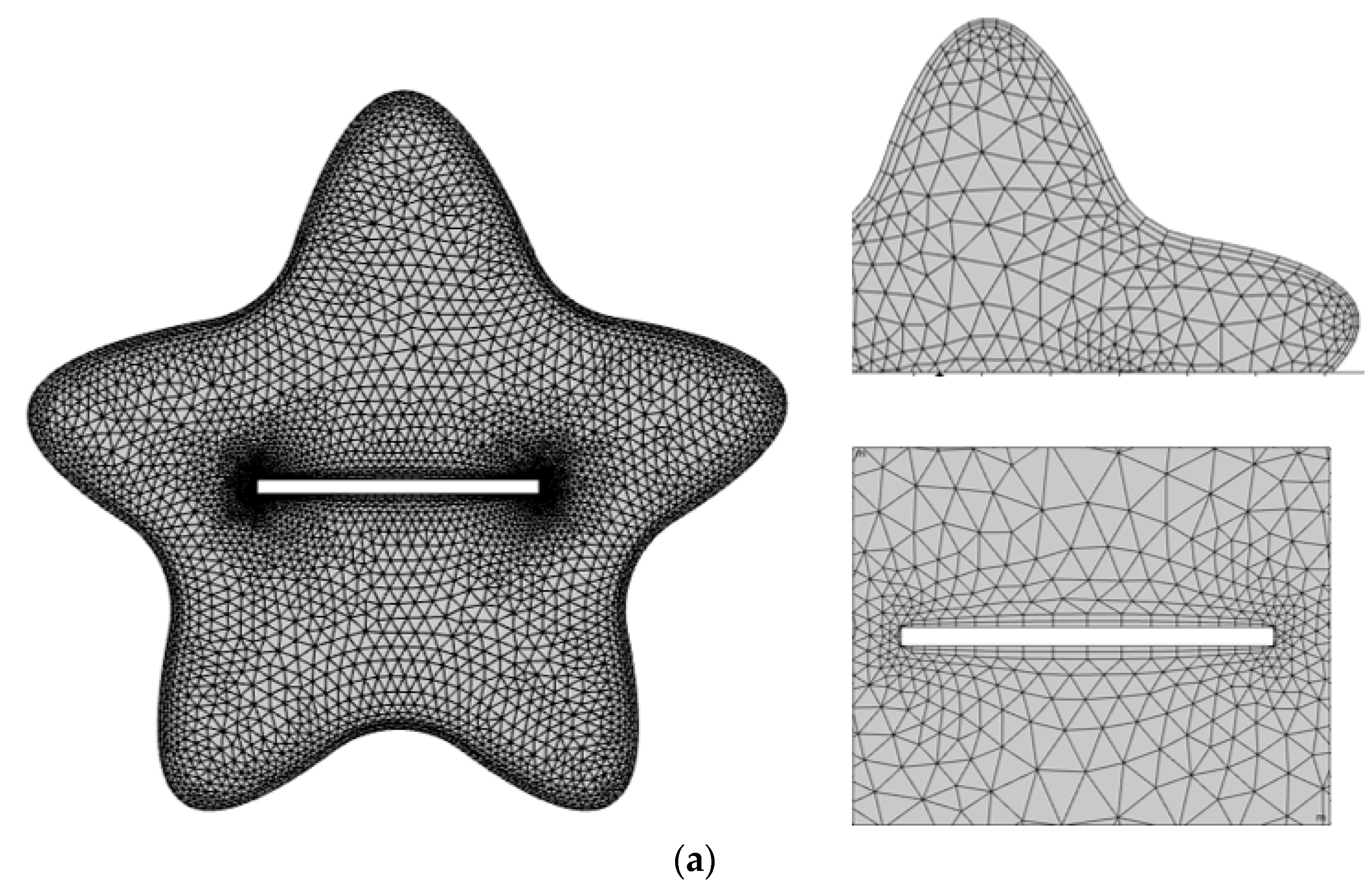
The concept of grid generation originated in the early 1990s, when numerous gigabits and testbeds, such as CASA [43], were developed to connect supercomputing facilities. Since then, the modeling of continuum mechanics problems is in the form of a set of partial differential equations. Only the simplest cases of these equations may usually be solved analytically. In most cases, the equations must be solved numerically. A discrete collection of points covering the physical region is required for numerical methods of solving partial differential equations. A well-structured grid can considerably simplify the solution of a system of partial differential equations. Therefore, grid generation is thus one of the most significant phases in calculating numerical solutions to a partial differential system. Since the presently considered phenomenon is regulated by flow and heat transfer, which are complex coupled equations, it is highly essential to discretize the domain into small portions, called elements. To attain an accurate solution for the involved field variables, structured and unstructured meshing are considered. Hybrid meshing, which is the combination of both structured and unstructured meshes, is selected in the present analysis. Meshes have a well-defined structure in terms of alignment with square and triangular elements in the 2D domain. Mesh generation is the process of creating an appropriate grid to approximate a solution inside various parts. This provides a comprehensive picture of fluid flow not only on boundaries but also in the domain. In addition, field variables describing the nature of the problem are required at the boundaries, and intermediate nodes and degrees of freedom are computed as shown in Table 2. Meshing at an extra-fine grid level is opted for to compute simulations for the problem, as illustrated in Figure 2a.

Grid Independence Test

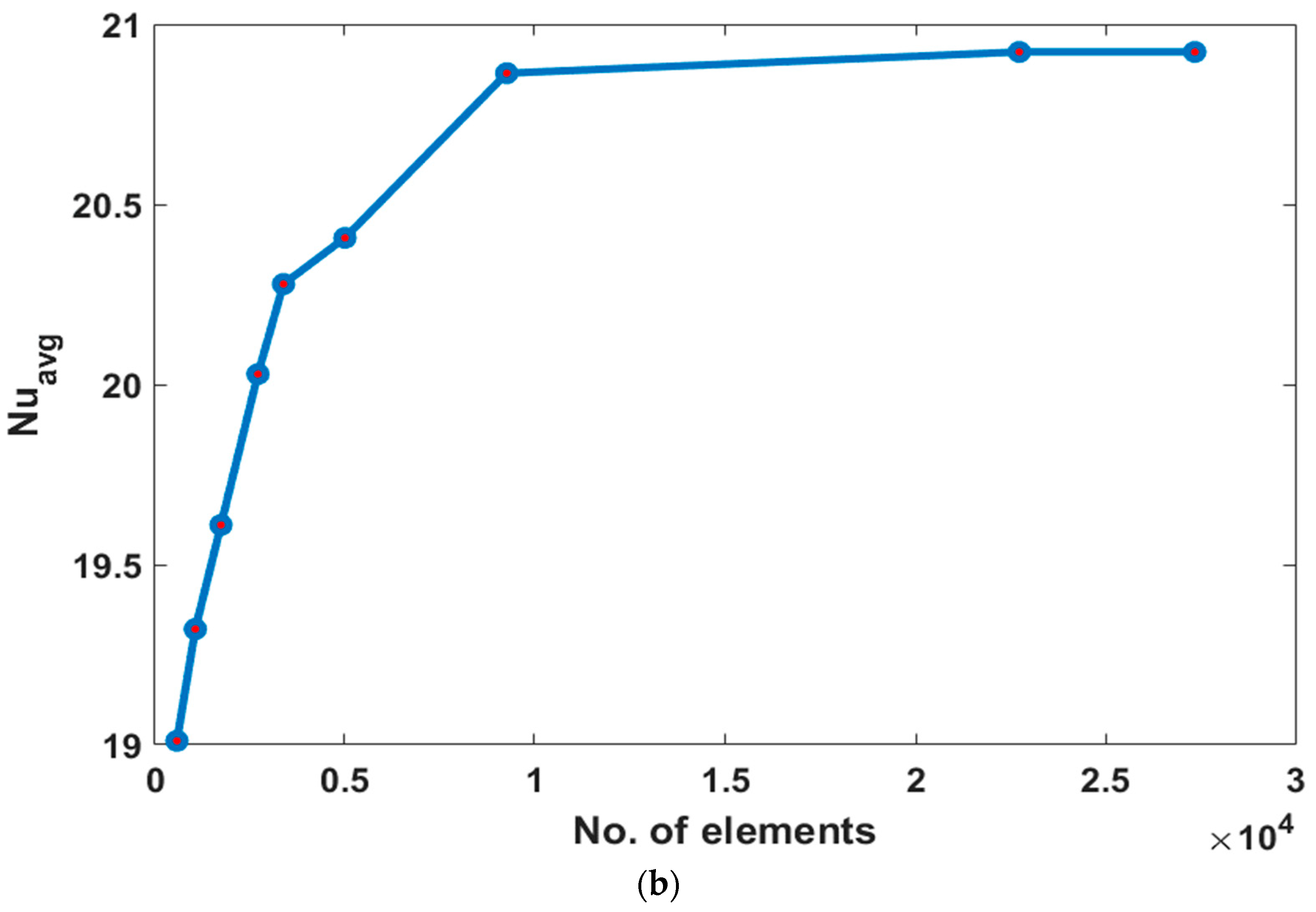
This test provides the sensitivity of the solution to the mesh refinement. By performing this test, it can be seen that by making the size of the elements smaller, the computed solution becomes less sensitive. Figure 2b is exhibited to show the grid dependency test for ϕ   = 0.02, Ra = 10 5 ,   P r = 6.8 , and H a = 20 , with the Nusselt number as a sensitive variable. It is observed that when the number of elements reaches 22,728, the average Nusselt number does not significantly vary. Therefore, all computations are performed at this element number, which is finer level of meshing.

3.4. Verification of the Numerical Model

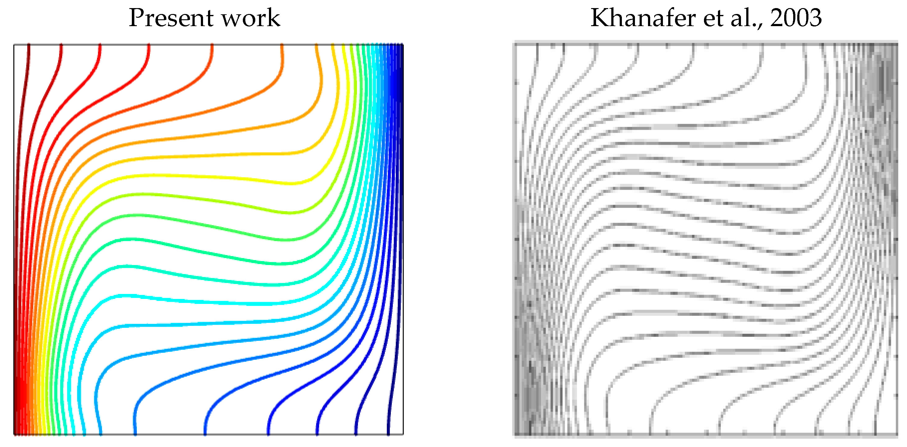
To ensure the accuracy and credibility of the established numerical model, a quantitative verification is performed by comparing the obtained values of the Nusselt number with the findings of Khanafer et al. [4]. In addition, a qualitative verification is performed by comparing the isotherms (Figure 3) for ϕ = 0.16 , Pr = 6.2, and R a = 10 4 with the results of Khanafer et al. [4]. The comparisons presented in Table 2 and Figure 3 show a very good concordance between the results.

4. Results and Discussions

In this paper, a numerical work is presented to study the flow structure, temperature field, and heat transfer rate for v a r i o u s values of the Rayleigh number ( 10 4 Ra 10 6 ) , Hartmann number ( 0 Ha 100 ) , and nanoparticle volume fraction ( 0.0 ϕ 0.05 ) . The Prandtl number P r = 6.2 is fixed throughout the numerical calculations.
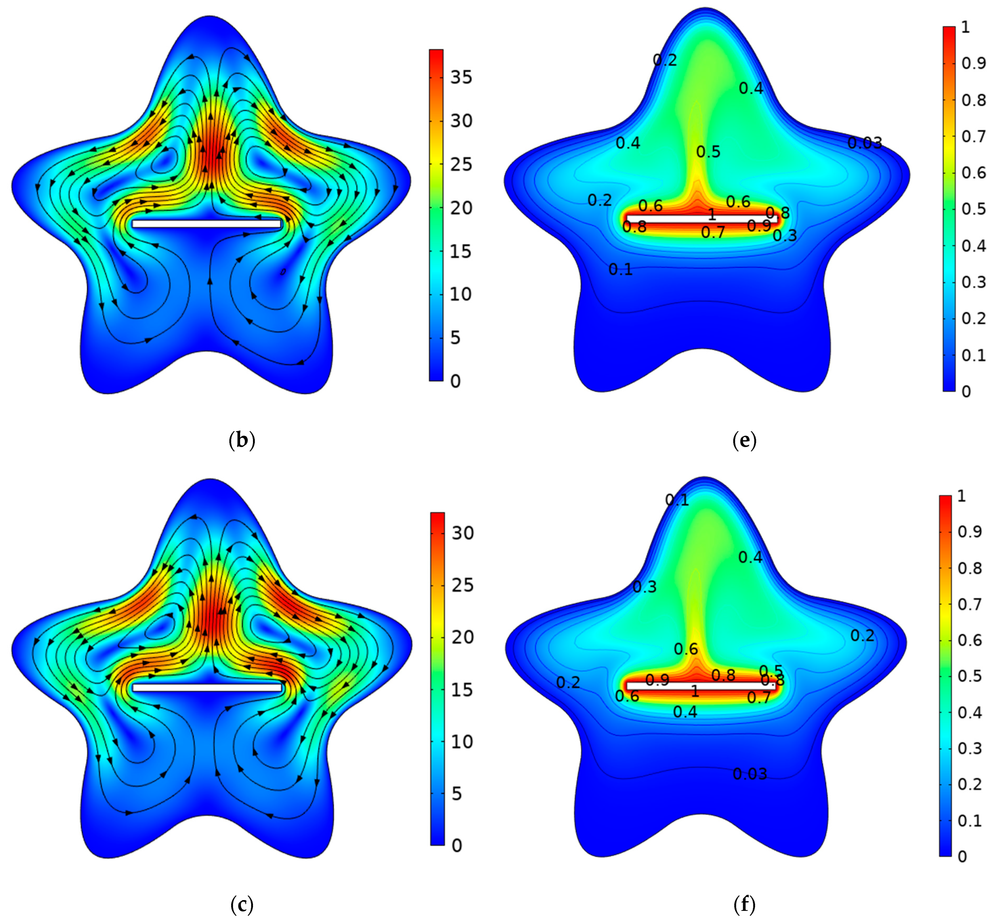
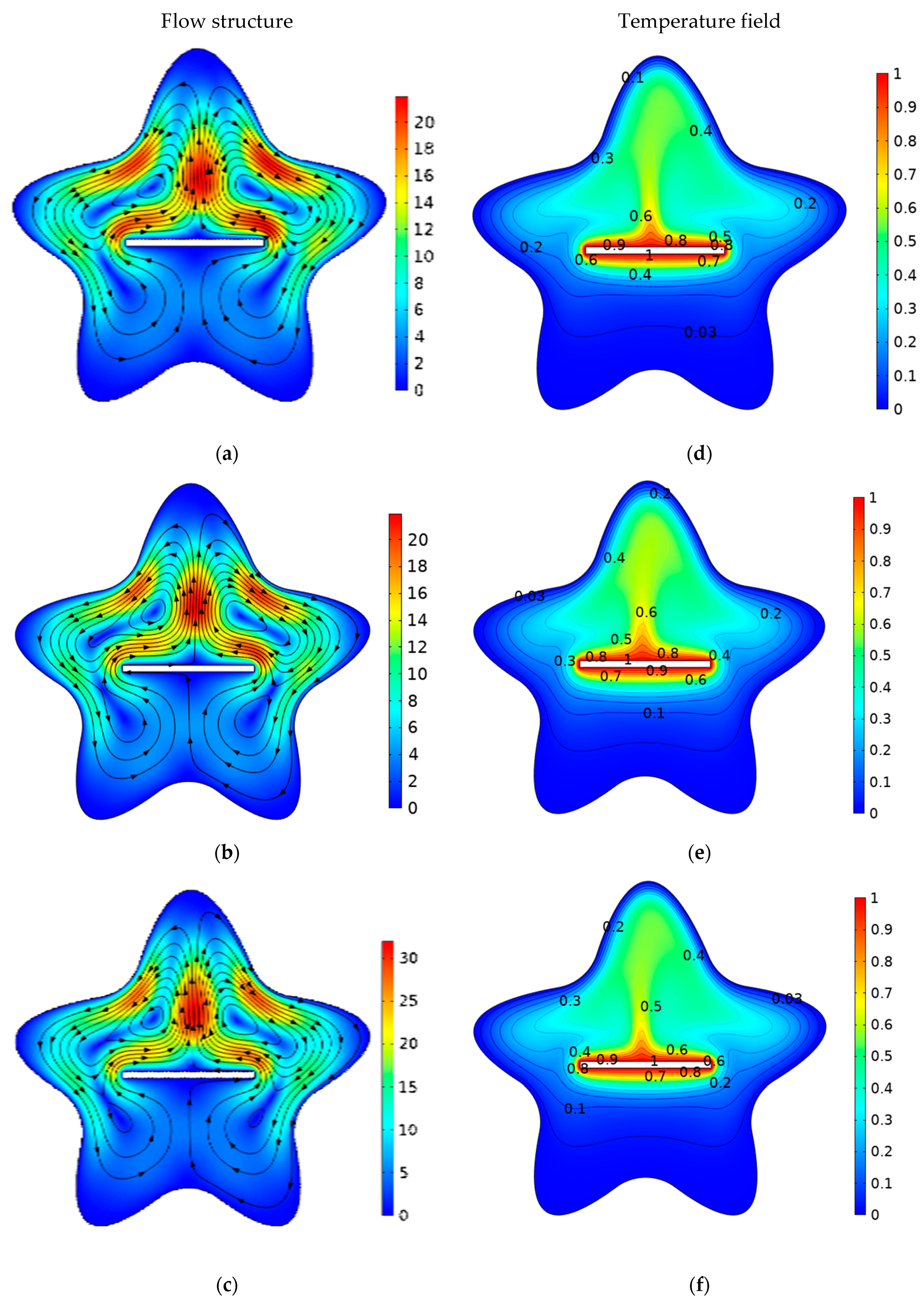
Figure 4 illustrates the flow structures and temperature fields for Pr = 6.2, Ha = 25, ϕ = 0.04 , and various Rayleigh number (Ra) values. From Figure 4a–c, it can be noted that when increasing the Rayleigh number (Ra), the magnitude of velocity increases. This increase is due to the enhancement of the buoyancy force generated by the density variations, especially close to the active hot and cold walls.
It should also be noted that the flow structure is symmetric for low Ra values. This symmetry disappears for Ra = 106 due to the dominance of the convective heat transfer mode compared to the conductive mode. The right column in Figure 4d–f depicts the temperature fields for various Rayleigh number (Ra) values. It is observed that by increasing (Ra), a vertical stratification of the isotherm is encountered, especially in the central region of the cavity. This fact indicates the enhancement of the convective heat transfer. It can also be seen that the t h e r m a l   b o u n d a r y   l a y e r   t h i c k n e s s reduces around the heated plate with increases in the (Ra). The reason for this behavior is that increasing the (Ra) leads to an increase in the temperature gradient.
Figure 5 illustrates the effect of the Hartman number of temperature and the velocity distributions for Ra = 105 and ϕ = 0.04 . Higher values of the Hartman number indicate a higher magnitude of the applied magnetic field. Figure 5a–c describe the nanofluid flow behavior for various Hartmann numbers (Ha). The velocity magnitude decreases with the increase in the Ha. This is due to the generated Lorentz forces, which oppose the fluid motion and reduce the flow intensity. Figure 5d–f describe the effect of the application of the external magnetic field on the temperature field. As previously mentioned, the applied magnetic field opposed the convective flow; thus, by increasing the Hartman number, the temperature gradients are reduced, especially close to the active walls.
The impacts of the volume fraction of the MWCNTs on the flow structure and isotherms are shown in Figure 6. Figure 6a–c show the effect of the solid volume fraction ϕ on the streamlines. For all the considered values of the volume fraction, the flow structure is characterized by two counter rotative cells. When the nanoparticle volume fraction is increased, the magnitude of the velocity increases. This increase is due to the intensification of the buoyancy force, which is caused by the enhancement of the thermophysical properties. Figure 6d–f present the temperature fields for various ϕ values. When the volume fraction is increased, the isotherms become more stuck to the active walls, indicating an increase in the temperature gradients and thus a higher heat transfer rate.
Figure 7a exhibits the profile of the horizontal velocity, components ( U * ) against the solid volume fraction ( ϕ ) by sketching the cutline at y = 0 and varying x from 1 x 1 . The velocity profile is discontinued due to the presence of the plate at 0.5   x 0.5 . The velocity increases by increasing the nanoparticle volume fraction ( ϕ ) due the enhancement of the buoyancy force. Figure 7b presents of the profile of the vertical velocity component ( V * ) against the solid volume fraction ( ϕ ) by sketching the cutline at x = 0 and varying y from 0.8 y 1.2 . Figure 7c displays the variation in the temperature distribution against ( ϕ ) by drawing a cut line at y = 0 and varying x from −1 to 1. 5. It is obvious that when the volume fraction of multiple walled carbon nanotube parameter rises, the temperature of fluid also increases. Figure 7d shows the local heat transfer around the rectangular heated plate. The local Nusselt number rises as the volume fraction of the MWCNT–water nanofluid increases. As the Nusselt number is the ratio of the convective to conductive heat transport in a fluid, the use of the MWCNTs increases the convective heat transfer in the fluid through the enhancement of the thermophysical properties. The highest heat transfer rate occurs for ( ϕ = 0.04 ).
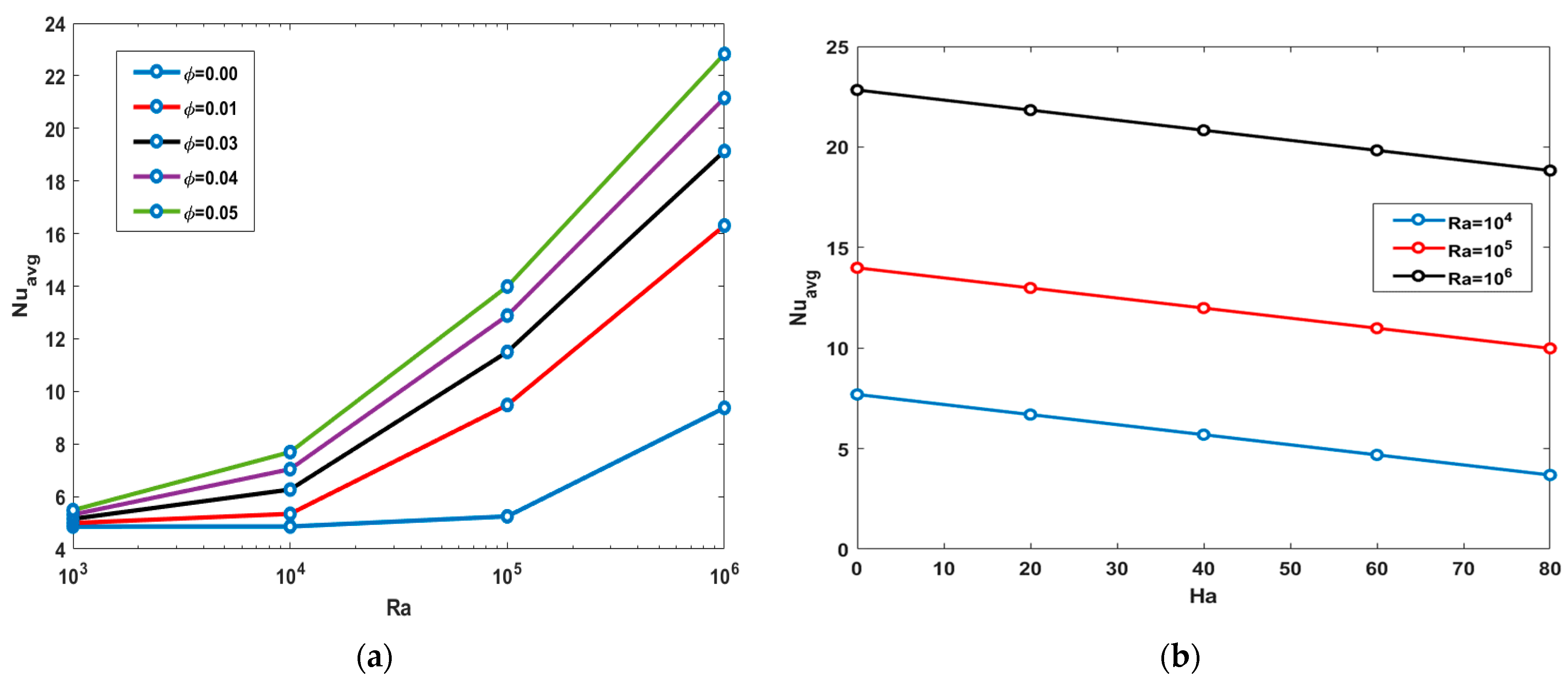
Figure 8a presents the effect of the Rayleigh number on the average Nusselt number for various nanoparticle volume fractions 0.0 ϕ 0.05 for Pr = 6.2 and H a = 25 . The increase in Ra values leads to the intensification of the convective recirculation flows, which causes the enhancement of the heat transfer rate. Similarly, the average Nusselt number is increased by the increase in the nanoparticle volume fraction due to the enhancement of the thermophysical properties. Figure 8b depicts the impact of the Hartmann number 20 H a 80 at various Rayleigh numbers 10 4 R a 10 6 on the average Nusselt number for Pr = 6.2 and ϕ = 0.04 .
The increase in the magnitude of the magnetic field causes the reduction of the heat transfer rate. This reduction is due to the decrease in the flow intensity caused by the generated Lorentz force. It should also be noted is that the magnetic field is more effective for higher Ra values. In fact, for low Ra values, the heat transfer regime is mainly conductive, and the fluid velocity is low; thus, the Lorentz force generated by the interaction between the fluid motion and the magnetic field is low.
Table 3 shows the variation in the average Nusselt number, and its percentage increase caused the addition of MWCNTs. It can be noted that the maximum heat transfer rate occurs when the nanoparticle volume fraction is 5%.

5. Conclusions

The current study is presented to investigate the convective heat transfer in a star-shaped cavity filled with an MWCNT–water nanofluid in the presence of an external uniform magnetic field and a heated installed plate. The problem is mathematically formulated as a dimensionless partial differential system. Finite-element-based computations are performed to find the solutions of the established governing equations. The results are presented in terms of temperature fields, flow structures, and variations of the average Nusselt number. The main results can be summarized as follows:
  • An intensification in flow circulation occurs when increasing the Rayleigh number due to the enhancement of the convective heat transfer.
  • The increase in the magnitude of the magnetic field causes a reduction in the velocity of the fluid due to the generated Lorentz force, which opposes the convective flow.
  • The addition of nanoparticles augments the heat transfer rate due to the enhancement of the thermophysical properties, and the highest value of the average Nusselt number occurs for ϕ = 0.05 .
  • The use of the MWCNTs increases the flow intensity due to the enhancement of the buoyancy force.

Author Contributions

Conceptualization, S.B. and I.A.S.; Methodology, S.B., I.A.S., K.G. and L.K.; Software, S.B. and I.A.S.; Validation, S.B. and I.A.S.; Formal analysis, S.B., I.A.S., K.G., A.A. and L.K.; Investigation, S.B., I.A.S. and A.A.; Writing—original draft, S.B., I.A.S., K.G., A.A. and L.K.; Writing—review & editing, S.B., I.A.S., K.G., A.A. and L.K.; Supervision, L.K.; Project administration, K.G. All authors have read and agreed to the published version of the manuscript.

Funding

Princess Nourah bint Abdulrahman University Researchers Supporting Project number (PNURSP2023R41), Princess Nourah bint Abdulrahman University, Riyadh, Saudi Arabia.

Institutional Review Board Statement

Not applicable.

Informed Consent Statement

Not applicable.

Data Availability Statement

Not applicable.

Conflicts of Interest

The authors declare no conflict of interest.

References

  1. Choi, S.U.; Eastman, J.A. Enhancing Thermal Conductivity of Fluids with Nanoparticles (No. ANL/MSD/CP-84938; CONF-951135-29); Argonne National Laboratory (ANL): Argonne, IL, USA, 1995. [Google Scholar]
  2. Das, S.K.; Choi, S.U.; Patel, H.E. Heat transfer in nanofluids—A review. Heat Transf. Eng. 2006, 27, 3–19. [Google Scholar] [CrossRef]
  3. Ho, C.; Chen, M.; Li, Z. Numerical simulation of natural convection of nanofluid in a square enclosure: Effects due to uncertainties of viscosity and thermal conductivity. Int. J. Heat Mass Transf. 2008, 51, 4506–4516. [Google Scholar] [CrossRef]
  4. Khanafer, K.; Vafai, K.; Lightstone, M. Buoyancy-driven heat transfer enhancement in a two-dimensional enclosure utilizing nanofluids. Int. J. Heat Mass Transf. 2003, 46, 3639–3653. [Google Scholar] [CrossRef]
  5. Oztop, H.F.; Abu-Nada, E. Numerical study of natural convection in partially heated rectangular enclosures filled with nanofluids. Int. J. Heat Fluid Flow 2008, 29, 1326–1336. [Google Scholar] [CrossRef]
  6. Bouchoucha, A.E.M.; Bessaïh, R. Natural convection in a square cavity filled with nanofluids. Fluid Dyn. Mater. Process. 2015, 11, 279–300. [Google Scholar]
  7. Duangthongsuk, W.; Wongwises, S. Heat transfer enhancement and pressure drop characteristics of TiO2–water nanofluid in a double-tube counter flow heat exchanger. Int. J. Heat Mass Transf. 2009, 52, 2059–2067. [Google Scholar] [CrossRef]
  8. Tasnim, S.H.; Collins, M.R. Numerical analysis of heat transfer in a square cavity with a baffle on the hot wall. Int. Commun. Heat Mass Transf. 2004, 31, 639–650. [Google Scholar] [CrossRef]
  9. Sheikholeslami, M.; Gorji-Bandpy, M.; Ganji, D.D. Numerical investigation of MHD effects on Al2O3–water nanofluid flow and heat transfer in a semi-annulus enclosure using LBM. Energy 2013, 60, 501–510. [Google Scholar] [CrossRef]
  10. Boulahia, Z.; Wakif, A.; Sehaqui, R. Numerical Investigation of Mixed Convection Heat Transfer of Nanofluid in a Lid Driven Square Cavity with Three Triangular Heating Blocks. Int. J. Comput. Appl. 2016, 143, 37–45. [Google Scholar] [CrossRef]
  11. Mejri, I.; Mahmoudi, A.; Abbassi, M.A.; Omri, A. Magnetic field effect on entropy generation in a nanofluid-filled enclosure with sinusoidal heating on both side walls. Powder Technol. 2014, 266, 340–353. [Google Scholar] [CrossRef]
  12. Garoosi, F.; Hoseininejad, F.; Rashidi, M.M. Numerical study of natural convection heat transfer in a heat exchanger filled with nanofluids. Energy 2016, 109, 664–678. [Google Scholar] [CrossRef]
  13. Armaghani, T.; Kasaeipoor, A.; Alavi, N.; Rashidi, M. Numerical investigation of water-alumina nanofluid natural convection heat transfer and entropy generation in a baffled L-shaped cavity. J. Mol. Liq. 2016, 223, 243–251. [Google Scholar] [CrossRef]
  14. Motlagh, S.Y.; Taghizadeh, S.; Soltanipour, H. Natural convection heat transfer in an inclined square enclosure filled with a porous medium saturated by nanofluid using Buongiorno’s mathematical model. Adv. Powder Technol. 2016, 27, 2526–2540. [Google Scholar] [CrossRef]
  15. Iijima, S. Helical microtubules of graphitic carbon. Nature 1991, 354, 56–58. [Google Scholar] [CrossRef]
  16. Jafari, M.; Farhadi, M.; Akbarzade, S.; Ebrahimi, M. Lattice Boltzmann simulation of natural convection heat transfer of SWCNT-nanofluid in an open enclosure. Ain Shams Eng. J. 2015, 6, 913–927. [Google Scholar] [CrossRef] [Green Version]
  17. Arani, A.A.A.; Akbari, O.A.; Safaei, M.R.; Marzban, A.; Alrashed, A.A.; Ahmadi, G.R.; Nguyen, T.K. Heat transfer improvement of water/single-wall carbon nanotubes (SWCNT) nanofluid in a novel design of a truncated double-layered microchannel heat sink. Int. J. Heat Mass Transf. 2017, 113, 780–795. [Google Scholar] [CrossRef]
  18. Ben Said, L.; Kolsi, L.; Ben Khedher, N.; Alshammari, F.; Malekshah, E.; Hussein, A. Numerical Study of the Fluid-Structure Interaction During CNT-Water Nanofluid Mixed Convection in a Micro-Channel Equipped with Elastic Fins Under Periodic Inlet Velocity Conditions. Exp. Tech. 2021, 47, 7–15. [Google Scholar] [CrossRef]
  19. Farooq, W.; Abbasi, A.; Al-Khaled, K.; Ghachem, K.; Khan, S.U.; Ahmad, I.; Kolsi, L. Thermal aspect of boron nitride nanotubes (BNNT) and multiwall carbon nanotubes (MWCNT) with distinct physical features: Keller Box simulations. J. Appl. Math. Mech. (ZAMM-Z. Fur Angew. Math. Und Mech.) 2022, 102, e202100560. [Google Scholar] [CrossRef]
  20. Cao, Y.; Ayed, H.; Jarad, F.; Togun, H.; Alias, H.; Issakhov, A.; Dahari, M.; Wae-Hayee, M.; El Ouni, M.H. MHD natural convection nanofluid flow in a heat exchanger: Effects of Brownian motion and thermophoresis for nanoparticles distribution. Case Stud. Therm. Eng. 2021, 28, 101394. [Google Scholar] [CrossRef]
  21. Haritha, C.; Shekar, B.C.; Kishan, N. MHD Natural Convection Heat Transfer in a Porous Square Cavity Filled by Nanofluids with Viscous Dissipation. J. Nanofluids 2018, 7, 928–938. [Google Scholar] [CrossRef]
  22. Redouane, F.; Jamshed, W.; Devi, S.; Prakash, M.; Nasir, N.A.A.M.; Hammouch, Z.; Eed, E.M. Heat flow saturate of Ag/MgO-water hybrid nanofluid in heated trigonal enclosure with rotate cylindrical cavity by using Galerkin finite element. Sci. Rep. 2022, 12, 1–20. [Google Scholar] [CrossRef]
  23. Sannad, M.; Hussein, A.K.; Abidi, A.; Homod, R.Z.; Biswal, U.; Ali, B.; Kolsi, L.; Younis, O. Numerical Study of MHD Natural Convection inside a Cubical Cavity Loaded with Copper-Water Nanofluid by Using a Non-Homogeneous Dynamic Mathematical Model. Mathematics 2022, 10, 2072. [Google Scholar] [CrossRef]
  24. Chamkha, A.J.; Dogonchi, A.; Ganji, D. Magnetohydrodynamic Nanofluid Natural Convection in a Cavity under Thermal Radiation and Shape Factor of Nanoparticles Impacts: A Numerical Study Using CVFEM. Appl. Sci. 2018, 8, 2396. [Google Scholar] [CrossRef] [Green Version]
  25. Hussam, W.K.; Khanafer, K.; Salem, H.J.; Sheard, G.J. Natural convection heat transfer utilizing nanofluid in a cavity with a periodic side-wall temperature in the presence of a magnetic field. Int. Commun. Heat Mass Transf. 2019, 104, 127–135. [Google Scholar] [CrossRef]
  26. Vijay, N.; Sharma, K. Magnetohydrodynamic hybrid nanofluid flow over a decelerating rotating disk with Soret and Dufour effects. Multidiscip. Model. Mater. Struct. 2023, 19, 253–276. [Google Scholar] [CrossRef]
  27. Sharma, K. FHD flow and heat transfer over a porous rotating disk accounting for Coriolis force along with viscous dissipation and thermal radiation. Heat Transf. 2022, 51, 4377–4392. [Google Scholar] [CrossRef]
  28. Ram, P.; Kumar, V. Revolving Ferrofluid Flow in Porous Medium with Rotating Disk. Int. J. Aerosp. Mech. Eng. 2013, 7, 1664–1669. [Google Scholar]
  29. Hussain, S.H.; Hussein, A.K. Numerical investigation of natural convection phenomena in a uniformly heated circular cylinder immersed in square enclosure filled with air at different vertical locations. Int. Commun. Heat Mass Transf. 2010, 37, 1115–1126. [Google Scholar] [CrossRef]
  30. Bararnia, H.; Soleimani, S.; Ganji, D. Lattice Boltzmann simulation of natural convection around a horizontal elliptic cylinder inside a square enclosure. Int. Commun. Heat Mass Transf. 2011, 38, 1436–1442. [Google Scholar] [CrossRef]
  31. De, A.K.; Dalal, A. A numerical study of natural convection around a square, horizontal, heated cylinder placed in an enclosure. Int. J. Heat Mass Transf. 2006, 49, 4608–4623. [Google Scholar] [CrossRef]
  32. Lee, J.; Ha, M.; Yoon, H. Natural convection in a square enclosure with a circular cylinder at different horizontal and diagonal locations. Int. J. Heat Mass Transf. 2010, 53, 5905–5919. [Google Scholar] [CrossRef]
  33. Kim, B.; Lee, D.; Ha, M.; Yoon, H. A numerical study of natural convection in a square enclosure with a circular cylinder at different vertical locations. Int. J. Heat Mass Transf. 2008, 51, 1888–1906. [Google Scholar] [CrossRef]
  34. Kim, M.; Doo, J.H.; Park, Y.G.; Yoon, H.S.; Ha, M.Y. Natural convection in a square enclosure with a circular cylinder according to the bottom wall temperature variation. J. Mech. Sci. Technol. 2014, 28, 5013–5025. [Google Scholar] [CrossRef]
  35. Ghalambaz, M.; Sabour, M.; Pop, I.; Wen, D. Free convection heat transfer of MgO-MWCNTs/EG hybrid nanofluid in a porous complex shaped cavity with MHD and thermal radiation effects. Int. J. Numer. Methods Heat Fluid Flow 2019, 29, 4349–4376. [Google Scholar] [CrossRef]
  36. Izadi, M.; Mohebbi, R.; Karimi, D.; Sheremet, M.A. Numerical simulation of natural convection heat transfer inside a┴ shaped cavity filled by a MWCNT-Fe3O4/water hybrid nanofluids using LBM. Chem. Eng. Process.-Process Intensif. 2018, 125, 56–66. [Google Scholar] [CrossRef]
  37. Ghasemi, B. Magnetohydrodynamic Natural Convection of Nanofluids in U-shaped Enclosures. Numer. Heat Transf. Part A Appl. 2013, 63, 473–487. [Google Scholar] [CrossRef]
  38. Pirmohammadi, M.; Ghassemi, M.; Sheikhzadeh, G.A. The effect of a magnetic field on buoyancy-driven convection in differentially heated square cavity. In Proceedings of the 2008 14th Symposium on Electromagnetic Launch Technology, Victoria, BC, Canada, 10–13 June 2008; pp. 1–6. [Google Scholar]
  39. Corcione, M. Heat transfer features of buoyancy-driven nanofluids inside rectangular enclosures differentially heated at the sidewalls. Int. J. Therm. Sci. 2010, 49, 1536–1546. [Google Scholar] [CrossRef]
  40. Haddad, Z.; Oztop, H.F.; Abu-Nada, E.; Mataoui, A. A review on natural convective heat transfer of nanofluids. Renew. Sustain. Energy Rev. 2012, 16, 5363–5378. [Google Scholar] [CrossRef]
  41. Maxwell, J.C. A Treatise on Electricity and Magnetism; Clarendon Press: Oxford, UK, 1873; Volume 1. [Google Scholar]
  42. Brinkman, H.C. The Viscosity of Concentrated Suspensions and Solutions. J. Chem. Phys. 1952, 20, 571. [Google Scholar] [CrossRef]
  43. Lyster, P.; Bergman, L.; Li, P.; Stanfill, D.; Crippe, B.; Blom, R.; Okaya, D. CASA gigabit supercomputing network: CALCRUST three-dimensional real-time multi-dataset rendering. Proc. Supercomput. 1992, 16, 3–37. [Google Scholar] [CrossRef]
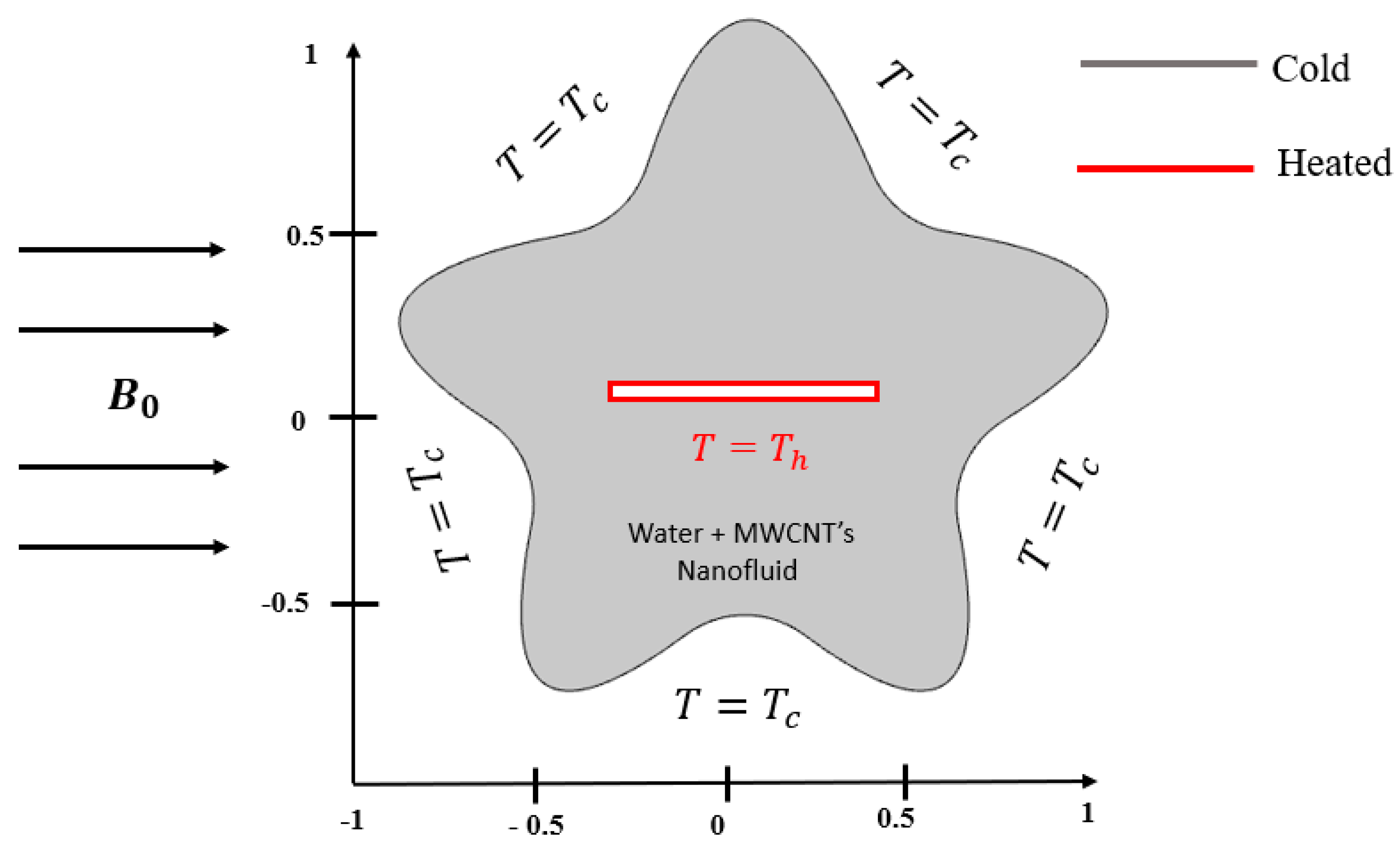
Figure 1. Graphical visualization of domain.
Mathematics 11 01849 g001
Figure 2. (a): A computational grid at finer level mesh. (b) Grid independence test.
Mathematics 11 01849 g002aMathematics 11 01849 g002b
Figure 3. Comparison between present and published results of Khanafer et al. [4] by fixing P r = 6.2 , R a = 6.2 × 10 4 , and ϕ = 0.16 .
Mathematics 11 01849 g003
Figure 4. Flow structures (ac) and temperature fields (df) for Ha = 25, ϕ = 0.04 , and various Rayleigh number (Ra) values. (a) Ra = 104; (b) Ra = 105; (c) Ra = 106; (d) Ra = 104; (e) Ra = 105; (f) Ra = 106.
Mathematics 11 01849 g004aMathematics 11 01849 g004b
Figure 5. Flow structures (ac) and temperature fields (df) for Ra = 105, ϕ = 0.04 , and various Hartman number (Ha) values. (a) Ha = 0; (b) Ha = 40; (c) Ha = 80; (d) Ha = 0; (e) Ha = 40; (f) Ha = 80.
Mathematics 11 01849 g005aMathematics 11 01849 g005b
Figure 6. Flow structures (ac) and temperature fields (df) for Ra = 105, H a = 25 , and various volume fraction values. (a) ϕ = 0.01; (b) ϕ = 0.02; (c) ϕ = 0.04; (d) ϕ = 0.0; (e) ϕ = 0.02; (f) ϕ = 0.04.
Mathematics 11 01849 g006
Figure 7. Variation of (a) horizontal velocity, (b) vertical velocity, (c) temperature, and (d) local Nusselt number with/respect to solid volume fraction ( ϕ ).
Mathematics 11 01849 g007
Figure 8. (a). Effect of Rayleigh number on the average Nusselt number for Ha = 25 and various nanoparticles volume fractions. (b) Effect of Hartman number on the average Nusselt number for ϕ = 0.04 and various Rayleigh numbers.
Mathematics 11 01849 g008
Table 1. Thermophysical characteristics of water and nanoparticles [36].
ρ   kg m 3 C p J kg   K k W m   K β   1 K σ Ω . m 1
Pure water997.141790.613 21 × 10 5 5.5 × 10 6
MWCNT21007113000 4.2 × 10 5 10 7
Table 2. Comparison of the average Nusselt number N u a v g with the results of Khanafer et al. [4] for various nanoparticles’ volume fractions at Pr = 6.2 and Ra = 6.2 × 10⁴.
N u a v g
Present Work Khanafer et al. [4]
ϕ = 0 4.09214.0975
ϕ = 0 .044.45984.4634
ϕ = 0.08 4.69384.6829
Table 3. Impact of volume fraction on Nusselt number with percentage enhancement.
ϕ N u a v g %
04.8425---
0.015.340010.27%
0.037.038731.81%
0.049.690337.45%
0.0514.264347.85%
Disclaimer/Publisher’s Note: The statements, opinions and data contained in all publications are solely those of the individual author(s) and contributor(s) and not of MDPI and/or the editor(s). MDPI and/or the editor(s) disclaim responsibility for any injury to people or property resulting from any ideas, methods, instructions or products referred to in the content.