Abstract
Engineering rock structures containing joints and fissures are frequently subjected to discontinuous periodic disturbances of varying amplitudes. To attain the quantitative relationship between the crack angle and the mechanical and deformation properties of rock under complex stress paths, uniaxial cyclic loading and unloading tests with increasing stress gradients were conducted on sandstone specimens containing a single crack of different angles. Our results showed that the bearing capacity of the sandstone increased as the crack angle increased. The irreversible strain and elastic moduli of the rock presented a sudden increase when entering the next cycle of the stepped loading. However, the entire loading process can be divided into three stages according to their respective trends. These three stages correspond to the three stages of rock deformation, i.e., the pore crack compaction stage, the elastic deformation to the stable micro-elastic crack development stage, and the unstable crack development stage. In addition, the crack angle of sandstone showed a negative correlation with the irreversible strain, but a positive correlation with the elastic modulus. With the increasing crack angle, the failure mode of the rock changed from the tensile-shear failure to the shear failure, and then to the interlayer dislocation failure.
Keywords:
mechanical and deformation characteristics; stress path; crack angle; constant lower limit; failure mode MSC:
86-05
1. Introduction
Defects such as joints and microcracks are widely contained in rocks [1,2,3]. These defects interconnect and develop during rock excavation, significantly affecting the stability of the underground projects. Numerous researchers have focused on the failure behavior of rock containing defects or planes in deep engineering projects [4,5,6]. For example, some scholars have evaluated the stability of tunnels and underground spaces containing cracks [7,8,9], and some analyzed the stability problems of jointed and cracked slopes [10,11].
Figure 1 shows that the mechanical behavior of the underground surrounding rocks with many cracks of various angles critically influences the safety of projects and leads to many uncertainties regarding the stability. To better solve these engineering problems, many researchers have conducted a large number of laboratory and numerical simulation experiments on cracked rocks and rock-like materials, and numerous mechanical properties of cracked rocks under ideal conditions have been obtained.
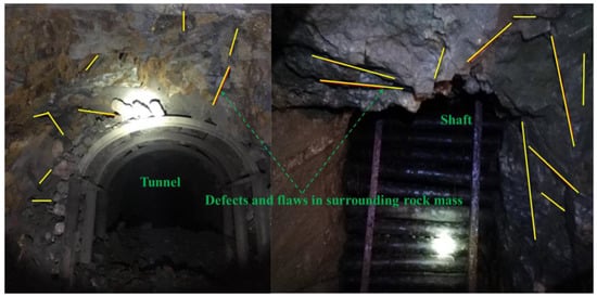
Figure 1.
Underground surrounding rock mass of tunnel and shaft containing defects (or flaws) at various angles.
In the laboratory tests, some scholars prefabricated single cracks [12], double cracks [13], triple cracks [14], and crack hole combinations [15] in rock-like materials [1,16] or rock materials [17,18]. In this manner, they investigated the influence of the crack length, angle, etc., on the rock strength and deformation as well as the crack propagation under uniaxial compression [19]. In addition, Cao et al. [20] summarized the multiple crack types and cut-through modes of the cracks and investigated the coalescence and failure modes of the cracks in rocks under uniaxial compression. The results showed that the coalescence mode of the cracks could be divided into three types, while their failure mode was partitioned into four types. By pre-casting two through-running cracks in rock-like specimens, Pu et al. [21] investigated the failure modes of the specimens with different crack inclinations under uniaxial compression conditions. Using the MTS815 (MTS refers to mechanical testing and simulation) rock mechanics testing system, Zhou et al. [22] studied the influences of the amplitude and frequency of the cyclic axial forces on the evolution of the displacement and permeability of the cracked rock. The results showed that rock disasters were more easily induced by dynamic axial forces with small amplitudes and high frequencies.
In a numerical simulation test, Wong et al. [23] separately performed uniaxial compression tests on specimens containing single, triple, and multiple cracks using the RFPA2D (realistic failure process analysis in two dimensions). The test results revealed that the spacing between the cracks and the crack location were important factors that influenced the crack initiation, propagation, and coalescence. Using the PFC2D (particle flow code in two dimensions), Zhang et al. [24] explored the initiation, propagation, and coalescence of two parallel cracks and obtained two crack coalescence modes. By applying a new numerical method, the general particle dynamics (GDP), Zhou et al. [25,26,27] investigated the whole process of the initiation, propagation, and coalescence of cracks in rock-like materials that contained multiple cracks under uniaxial compression, and observed four crack coalescence modes, including the tensile, compressive, shear, and tensile-shear modes. Wu et al. [28,29] investigated the deformation and cracking behavior of granite with hole inclusion under diametrical loading and reported that the inclusion had a positive effect on improving the load-bearing capacity of the specimen. They also studied the effect of infilling on the failure characteristics of sandstone with hole inclusion under uniaxial compression and found that the strength decreased as the stiffness of the infill material increased. Lin et al. [30] conducted uniaxial cyclic loading to study the fatigue behavior of cracked sandstone and reported that as the number of cycles increased, Young’s modulus gradually stabilized, while the secant modulus decreased non-linearly. The mechanical behavior of jointed rock with double circular holes under uniaxial compression was also investigated. It was found that the presence of non-persistent joints had a significant effect on the strength characteristics of the rock [31]. Dai et al. [32] conducted simulations using parallel bonded-particle models to investigate the cracking behavior of rock that contained intersecting flaws and observed two typical patterns of linkage the between the two intersecting flaws. Chen et al. [33] established a series of three-dimensional heterogeneous tunnel models with varying joint dip angles using the rock failure process analysis method, meso-damage mechanics, and the statistical strength theory. They found that the existence of parallel and random joints caused newly formed cracks to develop near the tunnel surface along their strikes.
The above literature review shows that the current studies on cracked rocks are mostly concentrated on a very simple stress path with monotonic loading or cyclic loading. The surrounding rocks are normally subjected to repeated disturbance with various amplitudes due to excavation and mining activities [34], causing the stress path to be more complicated. Importantly, our recent achievements revealed the energy characteristics and propagation laws of microcracks in fissured rock under complex stress paths [35,36]. However, the influence of the crack angle on the deformation and failure characteristics of fissured rock under stepped cyclic loading was not investigated (Figure 2). In this paper, we innovatively considered the excavation disturbance of the cracked rock mass as the discontinuous periodic cyclic loading with different amplitudes. Based on this, the mechanical and deformation characteristics of rocks with single cracks of different angles under stepped cyclic uniaxial compression were investigated. The related results provided evidence and guidance for the evaluation of the engineering stability and the selection of the support methods.
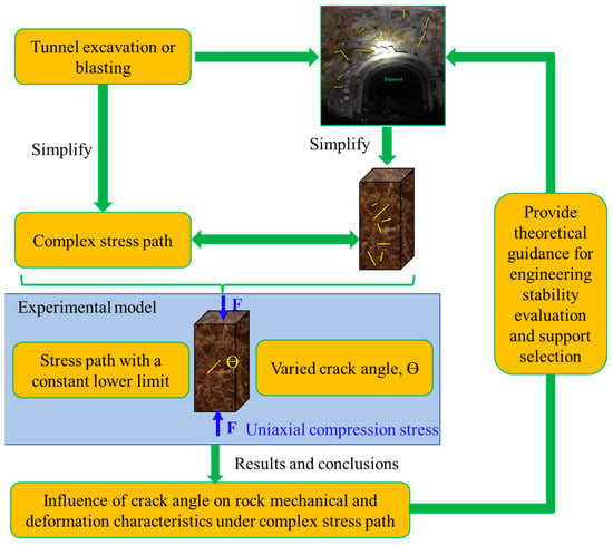
Figure 2.
Research idea of the failure and deformation behavior of the cracked rock under a complex stress path.
2. Experimental Material and Setup
2.1. Specimen Preparation
Sandstone is a kind of sedimentary rock and is commonly used in laboratory testing [37,38]. The sandstone specimens used in the experiment were prepared at the Laboratory of Coal Mine Disaster Dynamics and Control, Chongqing University, Chongqing city, China. The sandstone was first processed into cubes with dimensions of 30 mm × 60 mm × 120 mm, according to the aspect ratio standards (2.0~2.5) suggested by the International Society for Rock Mechanics. Afterwards, a single crack was cut through the center of the specimens, as shown in Figure 3. The specimen numbers and the geometric parameters of the cracks contained in the rock specimens are listed in Table 1. The length errors of all the specimens were less than 0.3 mm and the unevenness of both end faces after polishing was less than 0.02 mm. The end face was perpendicular to the axis, with a maximum deviation of less than 0.25°. To minimize the influence of the specimen inhomogeneity on the test results, all the specimens were taken from the same rock block.
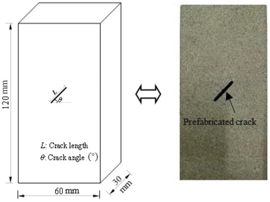
Figure 3.
Rock specimen and the related dimensions.

Table 1.
The geometrical parameters of the prefabricated cracks in the rock specimens.
In addition, to determine the mineral composition of the tested sandstone, X-ray diffraction (XRD) tests were performed on the sandstone specimens using the PANalyticalX’Pert powder from the Analytical and Testing Center at Chongqing University, Chongqing city, China. The related test procedure and results are shown in Figure 4. From the XRD test results, the minerals contained in the sandstone were mainly quartz (30.73%), microcline (11.11%), chlorite (16.72%), albite (35.23%), muscovite (5.41%), and a small amount of calcite (0.8%).
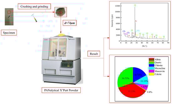
Figure 4.
The XRD test procedure and mineral components of the tested rock material.
2.2. Test Equipment
The MTS815 test system, manufactured by the State Key Laboratory of Coal Mine Disaster Dynamics and Control at Chongqing University, Chongqing city, China, was used in the experiment. The uniaxial cyclic loading and unloading tests on the rock materials was applied by the test machine. The test system had a high accuracy and stable performance and consisted of a control module, a loading and unloading module, and a data acquisition module. Additionally, the test system applied a maximum axial load of 2800 kN to the rock specimens. The MTS815 test system is shown in Figure 5 [28].
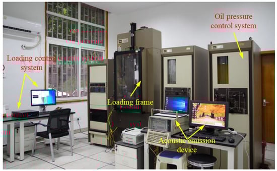
Figure 5.
The MTS815 test system.
2.3. Test Procedures
In the experiment, the rock specimens were compressed using a force control. As shown in Figure 6, the maximum force level at the first loading step was 9 kN. The upper limit of the applied force at the following force levels was progressively increased by 9 kN, whereas the lower force limit remained unchanged (0 kN) at all the force levels. The rock specimens suffered from 90 loading and unloading cycles at each force level, with a frequency of 0.3 Hz lasting for 5 min. All the tested rock specimens were compressed according to the designed loading path until the rock specimens were destroyed.
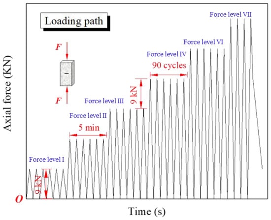
Figure 6.
The loading path in the stepped cyclic uniaxial compression test.
3. Calculation Methods of the Mechanical and Deformation Parameters
3.1. Irreversible Plastic Strain
Generally, rock specimens will deform under the action of an external force. After the external force is removed, the rock deformation gradually recovers, and the rock specimens exhibit elastic characteristics. However, due to the internal structural characteristics (various defects such as pores and cracks) of rocks, the rock specimens fail to recover to their initial states before deformation after the external force is removed. Furthermore, a certain amount of residual deformation or irreversible deformation occurs, which exhibits certain plastic characteristics. The method of calculating the irreversible (or plastic) strain is displayed in Figure 7.
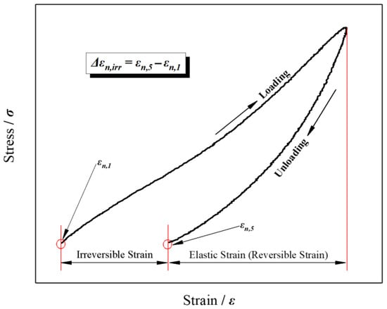
Figure 7.
Calculation method of the irreversible strain and elastic strain during a loading and unloading cycle.
The irreversible strain of the rock specimens refers to the difference between the strains recorded at the end and the beginning of a cycle. By processing the collected test data, the strains recorded at the beginning and the end of each cycle were calculated. Then, by substituting the data into Equation (1), the incremental irreversible strain of each cycle was attained.
where Δεn,irr and n refer to the incremental irreversible strain recorded in the nth loading and unloading cycle and the serial number of the cycle, respectively; and εn,3 and εn,1 refer to the strains recorded at the end and first points of the nth cycle, respectively. Therefore, through the accumulation, the irreversible strain can be obtained as the following.
where εi,irr represents the irreversible strain recorded at the ith cycle, Δεn,irr denotes the incremental irreversible strain recorded at the nth loading and unloading cycle, and N refers to the total number of loading and unloading cycles (1 ≤ i ≤ N).
3.2. Elastic Modulus
The elastic modulus is one of the important parameters used to describe the deformation resistance of rock materials. To some extent, the value of the elastic modulus can also reflect the initiation, propagation, and coalescence of the internal cracks in rocks. In this study, two types of methods were used to represent the elastic modulus, namely the loading elastic modulus and the unloading elastic modulus. According to the data acquisition law, the loading initial point, loading peak point, and unloading end point were found in each cycle and were recorded as n1, n2, and n3, respectively. Using the stress and strain data recorded at the three points, the loading modulus of the elasticity E1 and the unloading modulus of the elasticity E2 of each cycle were calculated separately. The schematic diagram for determining the two types of elastic moduli is shown in Figure 8. The related mathematical formulae are as follows.
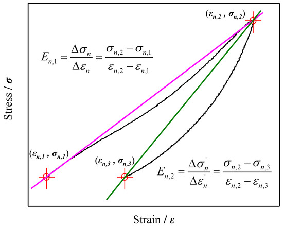
Figure 8.
Sketch for determination of the loading and unloading moduli.
The meanings of the symbols in Figure 8 are as follows: n denotes the serial number of the current cycle, and En,1 and En,2 represent the loading elastic modulus and the unloading elastic modulus in the nth cycle, respectively. Furthermore, Δσn and Δεn refer to the stress and strain differences between the loading peak point n2 (εn,2, σn,2) and the loading initial point n1 (εn,1, σn,1), respectively; and Δσn′, Δεn′ refer to the stress and strain differences between the loading peak point n2 (εn,2, σn,2) and the unloading end point n3 (εn,3, σn,3), respectively.
4. Test Results and Discussion
4.1. Stress–Strain Curves
Based on the data collected by the MTS815 rock mechanics test system, the stress–strain curves were obtained, as shown in Figure 9. For the stepped cyclic loading, the stress–strain curves of the cracked specimens with different crack angles all showed a “stepped” growth trend. By comparing the stress–strain curves of the different rock specimens, it was found that the larger the crack angle, the more the cyclic gradients were experienced by the specimen, and the greater the peak stress of the rock specimens. The test results of the rock specimens are summarized in Table 2. It can also be noted from Table 2 that the failure strain tended to decrease with the increasing crack angle. The increasing failure stress and decreasing failure strain indicate that the rock specimens underwent a more brittle failure as the crack angle increased. The reason may be that as the crack angle increases, the effective cross-sectional area of the crack decreases, resulting in a reduced effect on the rock failure stress. Due to the stress concentration at the tip of the crack, an increasing crack angle (decreasing effective cross-sectional area) also resulted in a higher stress level and a lower overall deformation, and thus, increased the rock brittleness. In terms of practical application in rock engineering, the advantage of a higher failure stress allows for a greater load-bearing capacity and stability of the rock structures. However, the disadvantage of a more brittle failure is that it can lead to sudden and catastrophic failure without warning, which can be dangerous in certain applications. Therefore, the support designs that can withstand higher failure stresses and effectively mitigate the risk of brittle failure are desired.
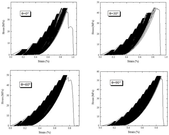
Figure 9.
The stress–strain curves of the pre-cracked rock specimens with four crack angles.
Table 2.
The strength and deformation parameters of the rock specimens.
4.2. Influence of the Crack Angle on the Peak Stress
From the stress–strain curves in the stepped cyclic loading tests, the crack angle showed a significant influence on the peak (failure) stress of the rock specimens. The quantitative relationship between the peak stress of the rock specimens and the crack angle is shown in Figure 10. There was a remarkable linear relationship between the peak stress and the crack angle of the rock specimens. That is, as the crack angle increased, the peak stress of the specimens increased linearly with a coefficient of determination of 0.9872. This showed that the crack angle had a significant influence on the rock strength. Therefore, in some geotechnical engineering tasks, it is necessary to ensure that the primary cracks in the rocks are vertical in order to increase their bearing capacity.
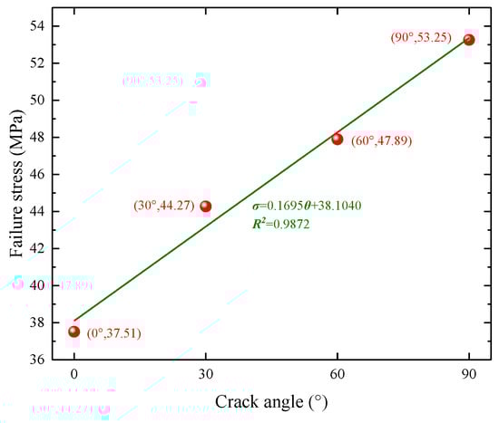
Figure 10.
Relationship between the crack angle and the peak stress of the rock specimens.
In addition, a comparison was made between our test results and those obtained by other researchers, as displayed in Figure 11. Table 3 presents the experimental schemes of the other researchers. It can be seen from Figure 11 that the peak stress of the cracked sandstone under monotonic uniaxial compression first decreased and then increased with an increase in the crack angle, while the peak stress of the pre-cracked sandstone under stepped cyclic uniaxial compression increased linearly. This indicates that the failure stress of pre-cracked rock was sensitive to both the loading path and the crack angle. The stepped cyclic loading made the crack compaction more predominant, and thus, increased the strength of the sandstone. However, compared to the crack angle, the stress path exerted a more pronounced effect on the peak stress of the pre-cracked rock.
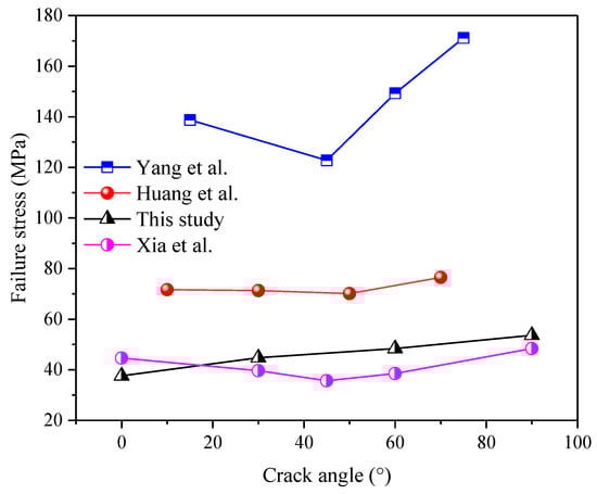
Figure 11.
Relationships between the peak stress and the crack angle of the rock under monotonic uniaxial compression and stepped cyclic uniaxial compression [12,27,39].
Table 3.
The experimental parameters and schemes in the existing literature.
4.3. Influence of the Crack Angle on the Irreversible Deformation
The irreversible strains of all the specimens were calculated separately using Equation (1). Figure 12 shows the changes in the irreversible strain during the entire stepped cyclic loading process. Although the crack angles were diverse, the irreversible strains all exhibited a consistent variation trend throughout the entire stepped cyclic loading process. The entire loading process can generally be divided into three stages: the initial stage (stage I), the steady stage (stage II), and the accelerated stage (stage III), as illustrated in Figure 12. Each stage was characterized by different mechanical behaviors and mechanisms. In stage I, the rock specimen underwent a crack compaction, which was characterized by the closure of pre-existing microcracks within the rock specimen. These pre-existing microcracks were sealed up when the force was applied because the mineral grains within the rock specimen were pushed closer. In stage II, the mechanism of deformation was the stretching and bending of the mineral grains within the rock specimen. The mineral grains within the rock specimen were forced to deform elastically under loading. This deformation was reversible, meaning that the rock specimen would return to its original shape when the force was removed. However, as the force was applied repeatedly in this study, stable micro-elastic cracks initiated within the rock specimen at a force level. In stage III, the deformation mechanism was the propagation of the macroscopic cracks through the rock specimen due to the stress concentration at the tips of the cracks. The propagation of the cracks led to a sudden drop in the load-carrying capacity of the rock specimen, resulting in failure. In summary, these three stages were characterized by the closure of pre-existing microcracks within the rock specimen, the elastic deformation of the mineral grains within the rock specimen, and the propagation of macroscopic cracks through the rock specimen due to the stress concentration at the crack tips.
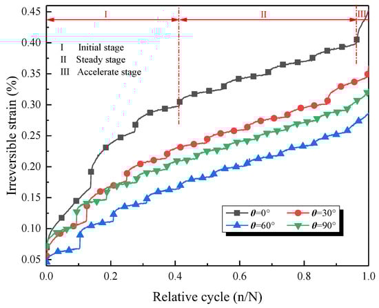
Figure 12.
Changes in the irreversible strain in the entire stepped cyclic loading process.
Figure 13 shows the changes in the irreversible strain of the specimens containing a single crack at different angles throughout the loading. Since the variation laws of the irreversible strain were similar for the different rock specimens, those of specimen T-0 were exemplified. The changes in the irreversible strain during the entire loading process with stress gradients were described. For specimen T-0, stage I included the first three force levels (i.e., levels I, II, and III). During this stage, the primary microcracks in the rock were gradually compacted under stepped cyclic loading. Therefore, the incremental irreversible strain gradually decreased while the irreversible strain accumulated at a rapid growth rate. The following four force levels (level IV, level V, level VI, and level VII) of the specimen T-0 belonged to stage II. After the rock specimen was compacted, new cracks were initiated and grew at a stable rate with the application of cyclic loading and with a higher upper limit of the force level. Hence, the irreversible deformation also developed at a stable rate. The accelerated stage involved the force level VIII of the specimen T-0. At this stage, the rock specimen transited from the elastic to the plastic phase, and the internal cracks in the specimen developed rapidly, resulting in a rapid accumulation of the irreversible strain. In addition, the cracks coalesced interactively, and the specimen eventually reached its peak strength and failed.
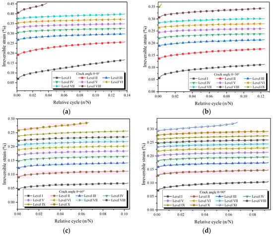
Figure 13.
Changes in the irreversible strain of the pre-cracked specimens at different force levels: (a) Ɵ = 0°, (b) Ɵ = 30°, (c) Ɵ = 60°, and (d) Ɵ = 90°.
To determine the essence of the irreversible strain evolution, the incremental irreversible strains in each cycle were calculated using Equation (2). Using the accumulation calculation, the incremental irreversible strain of the specimens at different force levels was attained, as shown in Figure 14. The incremental irreversible strains of all the specimens showed a “U-shaped” variation trend throughout the compression process. That is, the incremental irreversible strain first decreased, then remained basically unchanged, and finally increased again. This corresponded to the variation trend of the irreversible strain and was a favorable interpretation of the evolutionary trend of the irreversible strain.
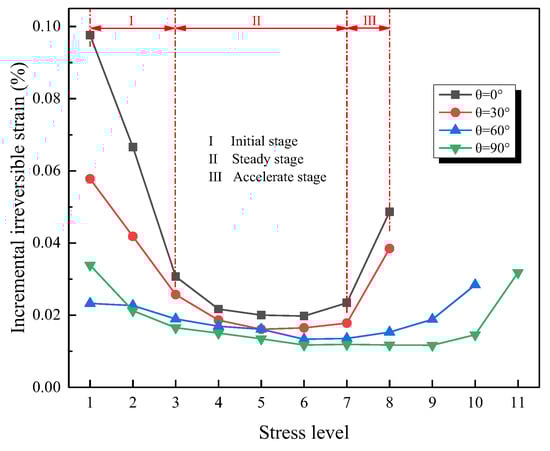
Figure 14.
Variation in the incremental irreversible strain at different force levels.
The variation trends of the irreversible strain and the incremental irreversible strain of the rock specimens were obtained in the early section. On this basis, the irreversible deformation of each specimen was divided into three stages: the initial stage, the steady stage, and the accelerated stage. The detailed classification of these three stages of the different rock specimens is shown in Table 4.
Table 4.
Force levels corresponding to the three stages of the irreversible deformation of the rock specimens.
In order to obtain the degree of influence of the crack angle on the irreversible deformation of the cracked rock, the two special types of the irreversible strain were determined, namely the initial irreversible strain (referring to the irreversible deformation at the end of the initial stage) and the terminal irreversible strain (i.e., the final irreversible deformation of the specimens), as shown in Figure 15. It can be seen that the crack angle was negatively correlated with the two types of the irreversible strain. That is, the larger the crack angle, the smaller the two types of the irreversible strain. The slope terms of the linear regressions of the initial and terminal irreversible strains were −0.0012 and −0.0015, respectively. This indicates that the terminal irreversible strain was more sensitive to the crack angle variation.
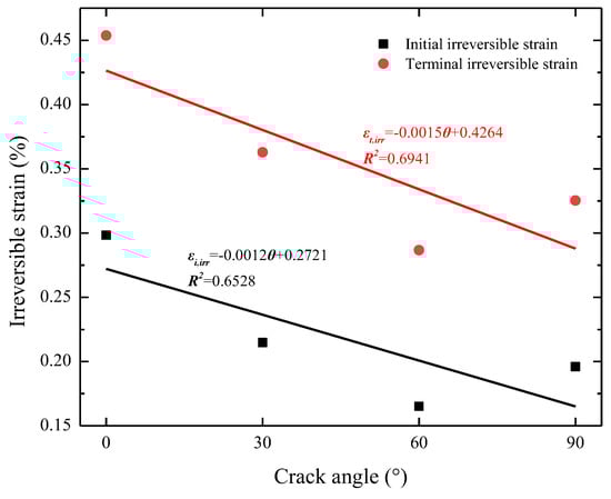
Figure 15.
Relationships between the crack angle and the initial and terminal irreversible strains.
4.4. Influence of the Crack Angle on the Elastic Moduli
Using the method in Section 3.2, the loading elastic modulus E1 and the unloading elastic modulus E2 of all the specimens were calculated during the entire compression process, as shown in Figure 16. Despite the different crack angles, either the loading elastic modulus E1 or the unloading elastic modulus E2 exhibited a consistent change trend during the entire stepped cyclic loading (Figure 16a,b). As the force level increased, the elastic moduli jumped. Within the force levels, the two elastic moduli showed three types of change: the initial growth type, the basically unchanged type, and the significant reduction type. In general, the loading elastic modulus E1 was slightly smaller than the unloading elastic modulus E2 for the same relative cycle (n/N), as shown in Figure 16c. This was because the rock was an inelastic material that underwent a somewhat plastic deformation during each loading cycle.
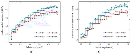
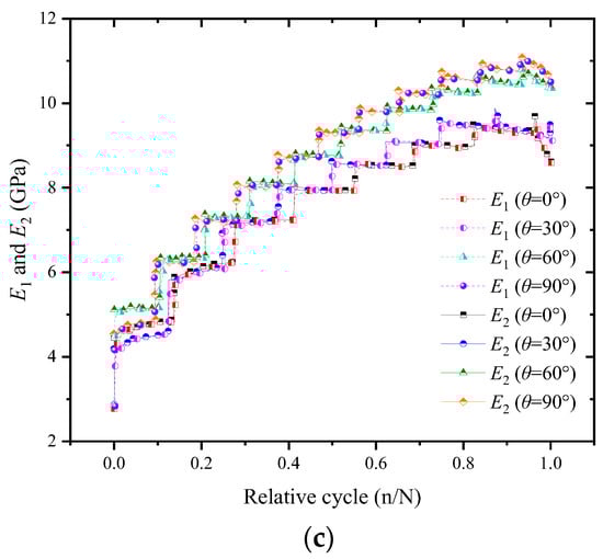
Figure 16.
Changes in the two types of elastic moduli during the stepped cyclic loading: (a) the loading elastic modulus E1, (b) the unloading elastic modulus E2, and (c) the comparison between the E1 and E2 of the rock specimens with different crack angles.
Figure 17 provides a detailed view of the two types of elastic moduli at different force levels. Both the loading and unloading elastic moduli exhibited similar trends of variation. Taking the experimental data of specimen T-0 as an example, three variation trends of the two types of elastic moduli at different force levels were described as follows. The force levels corresponding to each variation trend of the two types of elastic moduli are listed in Table 5.
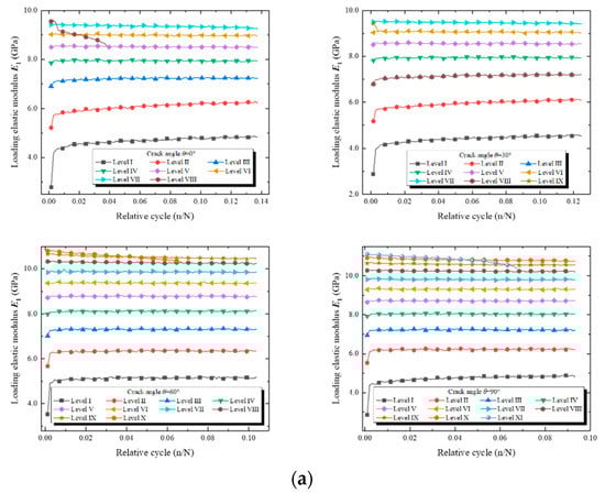
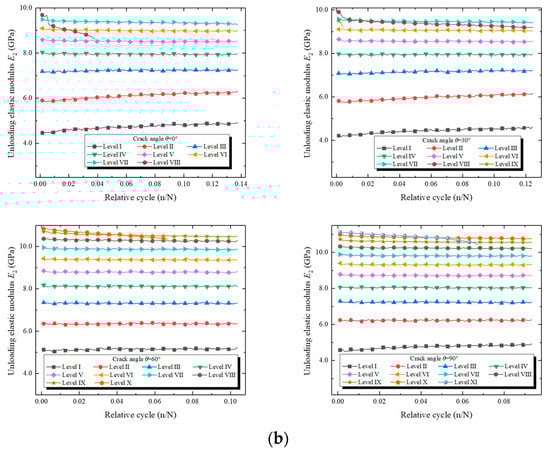
Figure 17.
The changes in the elastic moduli at different force levels: (a) the loading elastic modulus E1 and (b) the unloading elastic modulus E2.
Table 5.
The force levels corresponding to each variation trend of the elastic moduli of the rock specimens.
In the first variation trend, the two types of elastic moduli initially increased in the first three force levels (levels I, II, and III). During this stage, the pores and cracks within the rock specimen were compacted. As the compression continued, the primary micropores and cracks within the rock specimen were gradually closed. Therefore, the overall mechanical properties of the rock were strengthened in such cases, causing both the loading and unloading elastic moduli to increase with the relative cycle. As a result, the initial compression at each force level had a significant strengthening effect on the rock. This was because many primary micropores and cracks in the rock were closed during the initial loading.
In the second variation trend, the two types of elastic moduli basically remained unchanged at the four force levels (levels IV, V, VI, and VII). In this state, the rock was exactly in a stage of deformation where the elastic deformation was constantly evolving towards elastic microcracking. In general, the rocks exhibited the properties of an elastomer. In summary, in this case, the two types of elastic moduli basically remained unchanged at a given force level with the increasing relative cycle.
In the third variation trend, the two types of elastic moduli decreased sharply at force level VIII for specimen T-0. In this case, the rock specimen began to enter a plastic deformation phase, during which new cracks grew rapidly and visible cracks were noted on the specimen surface. Later, these cracks were interactively connected, and therefore, the two types of elastic moduli decreased significantly.
Figure 18 displays the relationships between the two types of elastic moduli (the loading elastic modulus and the unloading elastic modulus) and the crack angle at two specific relative cycles (n/N). These two types of elastic moduli were the elastic moduli at the initial stage (at the end of the first change in the trend of the elastic moduli) and at the terminal stage (at the end of the third change in the trend of the elastic moduli). As shown in Figure 18, it can be seen that the elastic moduli of the rock specimens increased as the crack angle increased. Moreover, there was a significant linear relationship between the two types of elastic moduli and the crack angle. At the initial stage, the unit influence factors of the crack angle on the loading elastic modulus E1 and the unloading elastic modulus E2 were 0.1119 and 0.1089, respectively. In contrast, at the terminal stage, the unit influence factors of the crack angle on these two types of elastic moduli were 0.2211 and 0.2158, respectively. Accordingly, it can be concluded that the larger the crack angle, the greater the elastic moduli, and the greater the deformation resistance of the rock. Correspondingly, the irreversible deformation accumulated in the rock during the entire stepped cyclic loading was reduced and the bearing capacity of the rock was improved. Thus, the compressive strength of the rock increased. This finding was fully consistent with the results obtained in Section 4.2 and Section 4.3.
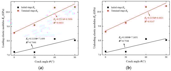
Figure 18.
The relationships between the elastic moduli and the crack angle of the cracks: (a) the loading elastic modulus E1 and (b) the unloading elastic modulus E2.
4.5. Influence of the Crack Angle on the Failure Mode of the Rock Specimens
Figure 19 shows the physical maps and related schematics of the fractured rock specimens after testing. The specimens T-0 and T-30 underwent a “Y-shaped” failure mode, i.e., the tensile-shear failure. The main cracks of these specimens were composed of one tensile crack and two shear cracks. Compared to the specimen T-0, specimen T-30 produced more shear cracks. When the crack angle varied from 0° to 30°, and to 60°, the failure mode of the rock specimens began to change from a mixed tensile-shear failure to a shear failure. The failure mode of specimen T-60 was a shear failure. The main crack of specimen T-60 extended and penetrated the upper or lower part of the existing crack at an inclination angle of 70° to the lower or upper part of the specimen, and finally showed an oblique shear failure. In addition, it can be observed from the end face of specimen T-90 that the failure mode was an interlamellar dislocation failure. Only a few small cracks developed in the front face of the rock specimen, and the existing cracks did not influence the failure mode of the rock specimen.
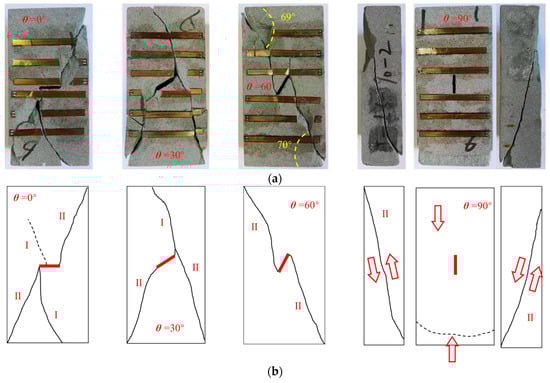
Figure 19.
Failure modes of the tested specimens: (a) pictures and (b) schematic diagrams (note: the red line represents the prefabricated crack and the red arrow refers to the potential moving direction of fractured rock pieces).
From the analysis above, it can be concluded that under the stepped cyclic compression, as the crack angle increased, the failure mode of the rock specimens transferred from the mixed tensile-shear failure to the shear failure and then to the interlamellar dislocation failure. This indicates that when the crack angle was large, secondary cracks were difficult to occur at the crack tip, and the failure of the specimen initiated from the weak interlaminar surface. It is well known that the shear strength is greater than the tensile strength of rocks. Combined with the failure mode of the rock specimens, the failure stress of the specimens should follow a sequence of T-90 > T-60 > T-30 > T-0, which is consistent with the test results.
5. Conclusions
In this study, stepped cyclic uniaxial compression tests with a constant lower limit were conducted on sandstone specimens containing a single crack with different crack angles. The influence of the crack angle on the mechanical and deformation characteristics of the sandstone was systematically investigated. The following conclusions were drawn.
- (1)
- It was found that the bearing capacity of the sandstone increased gradually as the crack angle increased. The bearing capacity of the pre-cracked rock was sensitive to both the crack angle and the stress path. Compared to the crack angle, the stress path exerted a more pronounced effect on the peak stress of the pre-cracked rock. There was a strong linear relationship between the peak stress and the crack angle, which was closely related to the failure mode of the rock specimens. The presence of large angle cracks made the rock more prone to shear failure.
- (2)
- The irreversible deformation of the pre-cracked sandstone could be divided into three stages before rock failure (including the initial stage, the steady stage, and the accelerated stage), which separately corresponded to the three deformation stages of the rocks before failure. As the crack angle increased, the irreversible deformation gradually decreased.
- (3)
- Both the loading elastic modulus and the unloading elastic modulus increased as the crack angle increased during the stepped cyclic loading. The two types of elastic moduli showed a significant linear relationship with the crack angle. In addition, the whole stepped cyclic loading process of the specimen could be divided into three stages: the initial growth stage, the basically unchanged stage, and the significant decrease stage.
- (4)
- Under stepped cyclic uniaxial compression, the failure mode of the pre-cracked rock specimens was closely related to the crack angle. As the crack angle increased, the failure mode changed from the mixed tensile-shear failure to the shear failure and then to the interlayer dislocation failure.
Compared to the results in the literature, the complex stress path significantly influenced the failure and deformation characteristics of the pre-cracked rock. Note that only sandstone was tested in this study, and therefore, more rock types should be tested to further validate our results. In addition, the pre-cracked sandstone was only tested under uniaxial compression, making the experimental results more practical for rock engineering, and the deformation and failure characteristics of pre-cracked rock should be tested under biaxial and triaxial stress states.
Author Contributions
Methodology, S.L. and H.L.; Writing—original draft, Y.W. (Yuanmin Wang) and Y.W. (Yunqiang Wang); Writing—review & editing, S.L.; Funding acquisition, K.P.; Data curation, Y.W. (Yuanmin Wang); Formal analysis, Y.W. (Yunqiang Wang) and S.L.; Investigation, H.L. and G.Y.; Supervision, K.P. All authors have read and agreed to the published version of the manuscript.
Funding
This work was funded by the National Natural Science Foundation of China (No. 51974043) and the Hunan Provincial Natural Science Foundation for Distinguished Young Scholars (2023JJ10072); the Hunan Province Furong Plan—Huxiang Youth Talent Program (2022RC1173).
Institutional Review Board Statement
Not applicable.
Informed Consent Statement
Not applicable.
Data Availability Statement
All the data, models, and code generated or used during the study appear in the submitted article.
Acknowledgments
The authors also thank the editor and anonymous reviewers for their valuable advice.
Conflicts of Interest
The authors declare that we do not have any commercial or associative interests that represent any conflicts of interest in connection with the work submitted.
References
- Wong, R.; Chau, K.; Tang, C.; Lin, P. Analysis of crack coalescence in rock-like materials containing three flaws—Part I: Experimental approach. Int. J. Rock Mech. Min. Sci. 2001, 38, 909–924. [Google Scholar] [CrossRef]
- Cao, P.; Liu, T.; Pu, C.; Lin, H. Crack propagation and coalescence of brittle rock-like specimens with pre-existing cracks in compression. Eng. Geol. 2014, 187, 113–121. [Google Scholar] [CrossRef]
- Luo, K.; Zhao, G.; Zeng, J.; Zhang, X.; Pu, C. Fracture experiments and numerical simulation of cracked body in rock-like materials affected by loading rate. Chin. J. Rock Mech. Eng. 2018, 37, 1833–1842. [Google Scholar] [CrossRef]
- Si, X.; Luo, S.; Luo, Y. A Review of Mechanical Properties and Rockburst Investigation of Transversely Isotropic Rocks by Experimental Technique. Materials 2023, 16, 3183. [Google Scholar] [CrossRef]
- Si, X.; Li, X.; Gong, F.; Huang, L.; Ma, C. Experimental investigation on rockburst process and characteristics of a circular opening in layered rock under three-dimensional stress conditions. Tunn. Undergr. Space Technol. 2022, 127, 104603. [Google Scholar] [CrossRef]
- Dai, B.; Zhao, G.; Zhang, L.; Liu, Y.; Zhang, Z.; Luo, X.; Chen, Y. Energy Dissipation of Rock with Different Parallel Flaw Inclinations under Dynamic and Static Combined Loading. Mathematics 2022, 10, 4082. [Google Scholar] [CrossRef]
- Feng, X.-T.; Guo, H.-S.; Yang, C.-X.; Li, S.-J. In situ observation and evaluation of zonal disintegration affected by existing fractures in deep hard rock tunneling. Eng. Geol. 2018, 242, 1–11. [Google Scholar] [CrossRef]
- Zhou, Y.-Y.; Xu, D.-P.; Gu, G.-K.; Liu, K.; Wan, L.-P.; Wang, T.-L.; Yang, J.-B. The failure mechanism and construction practice of large underground caverns in steeply dipping layered rock masses. Eng. Geol. 2019, 250, 45–64. [Google Scholar] [CrossRef]
- Gong, F.-Q.; Si, X.-F.; Li, X.-B.; Wang, S.-Y. Dynamic triaxial compression tests on sandstone at high strain rates and low confining pressures with split Hopkinson pressure bar. Int. J. Rock Mech. Min. Sci. 2018, 113, 211–219. [Google Scholar] [CrossRef]
- Elmo, D.; Donati, D.; Stead, D. Challenges in the characterisation of intact rock bridges in rock slopes. Eng. Geol. 2018, 245, 81–96. [Google Scholar] [CrossRef]
- Zheng, Y.; Chen, C.; Liu, T.; Song, D.; Meng, F. Stability analysis of anti-dip bedding rock slopes locally reinforced by rock bolts. Eng. Geol. 2019, 251, 228–240. [Google Scholar] [CrossRef]
- Yang, S.-Q.; Jing, H.-W. Strength failure and crack coalescence behavior of brittle sandstone samples containing a single fissure under uniaxial compression. Int. J. Fract. 2010, 168, 227–250. [Google Scholar] [CrossRef]
- Yang, S.-Q. Crack coalescence behavior of brittle sandstone samples containing two coplanar fissures in the process of deformation failure. Eng. Fract. Mech. 2011, 78, 3059–3081. [Google Scholar] [CrossRef]
- Yang, S.Q.; Yang, D.S.; Jing, H.W.; Li, Y.H.; Wang, S. An Experimental Study of the Fracture Coalescence Behaviour of Brittle Sandstone Specimens Containing Three Fissures. Rock Mech. Rock Eng. 2011, 45, 563–582. [Google Scholar] [CrossRef]
- Yang, S.-Q.; Jing, H.-W.; Huang, Y.-H.; Ranjith, P.; Jiao, Y.-Y. Fracture mechanical behavior of red sandstone containing a single fissure and two parallel fissures after exposure to different high temperature treatments. J. Struct. Geol. 2014, 69, 245–264. [Google Scholar] [CrossRef]
- Wang, D.-J.; Tang, H.; Elsworth, D.; Wang, C. Fracture evolution in artificial bedded rocks containing a structural flaw under uniaxial compression. Eng. Geol. 2019, 250, 130–141. [Google Scholar] [CrossRef]
- Wong, L.; Einstein, H. Systematic evaluation of cracking behavior in specimens containing single flaws under uniaxial compression. Int. J. Rock Mech. Min. Sci. 2008, 46, 239–249. [Google Scholar] [CrossRef]
- Yin, Q.; Jing, H.-W.; Zhu, T.-T. Experimental Study on Mechanical Properties and Cracking Behavior of Pre-cracked Sandstone Specimens Under Uniaxial Compression. Indian Geotech. J. 2016, 47, 265–279. [Google Scholar] [CrossRef]
- Xu, L.; Gong, F.; Luo, S. Effects of pre-existing single crack angle on mechanical behaviors and energy storage characteristics of red sandstone under uniaxial compression. Theor. Appl. Fract. Mech. 2021, 113, 102933. [Google Scholar] [CrossRef]
- Cao, R.H.; Cao, P.; Lin, H. Crack Coalescence and Failure Patterns in Brittle Rock-Like Specimens with Pre-Existing Fissures under Uniaxial Loading: Experimental Studies. Key Eng. Mater. 2015, 665, 117–120. [Google Scholar] [CrossRef]
- Pu, C.; Cao, P.; Yi, Y. Fracture for rock-like materials with two transfixion fissures under uniaxial compression. J. Cent. South Univ. 2012, 43, 2708–2716. [Google Scholar]
- Zhou, Z.; Zhang, J.; Cai, X.; Wang, S.; Du, X.; Zang, H.; Chen, L. Permeability Evolution of Fractured Rock Subjected to Cyclic Axial Load Conditions. Geofluids 2020, 2020, 1–12. [Google Scholar] [CrossRef]
- Wong, R.; Tang, C.; Chau, K.; Lin, P. Splitting failure in brittle rocks containing pre-existing flaws under uniaxial compression. Eng. Fract. Mech. 2002, 69, 1853–1871. [Google Scholar] [CrossRef]
- Zhang, X.-P.; Wong, L.N.Y. Cracking Processes in Rock-Like Material Containing a Single Flaw Under Uniaxial Compression: A Numerical Study Based on Parallel Bonded-Particle Model Approach. Rock Mech. Rock Eng. 2011, 45, 711–737. [Google Scholar] [CrossRef]
- Zhou, X.P.; Bi, J.; Qian, Q.H. Numerical Simulation of Crack Growth and Coalescence in Rock-Like Materials Containing Multiple Pre-existing Flaws. Rock Mech. Rock Eng. 2014, 48, 1097–1114. [Google Scholar] [CrossRef]
- Peng, K.; Lv, H.; Zou, Q.; Wen, Z.; Zhang, Y. Evolutionary characteristics of mode-I fracture toughness and fracture energy in granite from different burial depths under high-temperature effect. Eng. Fract. Mech. 2020, 239, 107306. [Google Scholar] [CrossRef]
- Huang, D.; Cen, F.; Huang, R.Q. Influence of medium strain rate on sandstone with a single pre-crack under uniaxial compression using PFC simulation. Rock Soil Mech. 2013, 34, 535–545. [Google Scholar] [CrossRef]
- Wu, Q.; Weng, L.; Zhao, Y.; Zhao, F.; Peng, W.; Zhang, S. Deformation and cracking characteristics of ring-shaped granite with inclusion under diametrical compression. Arab. J. Geosci. 2020, 13, 1–11. [Google Scholar] [CrossRef]
- Wu, Q.-H.; Weng, L.; Zhao, Y.-L.; Feng, F. Influence of infilling stiffness on mechanical and fracturing responses of hollow cylindrical sandstone under uniaxial compression tests. J. Cent. South Univ. 2021, 28, 2485–2498. [Google Scholar] [CrossRef]
- Lin, Q.; Cao, P.; Mao, S.; Ou, C.; Cao, R. Fatigue behaviour and constitutive model of yellow sandstone containing pre-existing surface crack under uniaxial cyclic loading. Theor. Appl. Fract. Mech. 2020, 109, 102776. [Google Scholar] [CrossRef]
- Lin, Q.; Cao, P.; Cao, R.; Lin, H.; Meng, J. Mechanical behavior around double circular openings in a jointed rock mass under uniaxial compression. Arch. Civ. Mech. Eng. 2020, 20, 19. [Google Scholar] [CrossRef]
- Dai, B.; Chen, Y.; Zhao, G.; Liang, W.; Wu, H. A Numerical Study on the Crack Development Behavior of Rock-Like Material Containing Two Intersecting Flaws. Mathematics 2019, 7, 1223. [Google Scholar] [CrossRef]
- Chen, B.; Gong, B.; Wang, S.; Tang, C. Research on Zonal Disintegration Characteristics and Failure Mechanisms of Deep Tunnel in Jointed Rock Mass with Strength Reduction Method. Mathematics 2022, 10, 922. [Google Scholar] [CrossRef]
- Shang, Y.; Kong, D.; Pu, S.; Xiong, Y.; Li, Q.; Cheng, Z. Study on Failure Characteristics and Control Technology of Roadway Surrounding Rock under Repeated Mining in Close-Distance Coal Seam. Mathematics 2022, 10, 2166. [Google Scholar] [CrossRef]
- Wang, Y.-Q.; Peng, K.; Shang, X.-Y.; Li, L.-P.; Liu, Z.-P.; Wu, Y.; Long, K. Experimental and numerical simulation study of crack coalescence modes and microcrack propagation law of fissured sandstone under uniaxial compression. Theor. Appl. Fract. Mech. 2021, 115, 103060. [Google Scholar] [CrossRef]
- Peng, K.; Wang, Y.; Zou, Q.; Cheng, Y.; Song, X. Experimental study of energy dissipation characteristics and crack coalescence modes of cracked sandstone under different cyclic loading paths. Bull. Eng. Geol. Environ. 2021, 80, 5881–5895. [Google Scholar] [CrossRef]
- Luo, S.; Gong, F. Evaluation of energy storage and release potentials of highly stressed rock pillar from rockburst control perspectives. Int. J. Rock Mech. Min. Sci. 2023, 163, 105324. [Google Scholar] [CrossRef]
- Luo, S.; Gong, F.Q.; Li, L.L.; Peng, K. Linear energy storage and dissipation laws and damage evolution characteristics of rock under triaxial cyclic compression with different confining pressure. Trans. Nonferrous Met. Soc. China 2022, 10, 1–27. Available online: https://kns.cnki.net/kcms/detail/43.1239.TG.20220630.1050.010.html (accessed on 1 July 2022).
- Xia, B.; Li, Y.; Hu, H.; Luo, Y.; Peng, J. Effect of Crack Angle on Mechanical Behaviors and Damage Evolution Characteristics of Sandstone Under Uniaxial Compression. Rock Mech. Rock Eng. 2022, 55, 6567–6582. [Google Scholar] [CrossRef]


Disclaimer/Publisher’s Note: The statements, opinions and data contained in all publications are solely those of the individual author(s) and contributor(s) and not of MDPI and/or the editor(s). MDPI and/or the editor(s) disclaim responsibility for any injury to people or property resulting from any ideas, methods, instructions or products referred to in the content. |
© 2023 by the authors. Licensee MDPI, Basel, Switzerland. This article is an open access article distributed under the terms and conditions of the Creative Commons Attribution (CC BY) license (https://creativecommons.org/licenses/by/4.0/).