Article

Influence of Homo- and Hetero-Junctions on the Propagation Characteristics of Radially Propagated Cylindrical Surface Acoustic Waves in a Piezoelectric Semiconductor Semi-Infinite Medium

1
School of Mathematics and Physics, University of Science and Technology Beijing, Beijing 100083, China
2
Department of Applied Mechanics, University of Science and Technology Beijing, Beijing 100083, China
3
School of Civil and Resource Engineering, University of Science and Technology Beijing, Beijing 100083, China
*
Author to whom correspondence should be addressed.
Mathematics 2024, 12(1), 145; https://doi.org/10.3390/math12010145
Submission received: 14 October 2023 / Revised: 9 December 2023 / Accepted: 13 December 2023 / Published: 2 January 2024
(This article belongs to the Special Issue Advances in Applied Mathematics, Mechanics and Engineering)

Abstract

:
This paper theoretically investigates the influence of homo- and hetero-junctions on the propagation characteristics of radially propagated cylindrical surface acoustic waves in a piezoelectric semiconductor semi-infinite medium. First, the basic equations of the piezoelectric semiconductor semi-infinite medium are mathematically derived. Then, based on these basic equations and the transfer matrix method, two equivalent mathematical models are established concerning the propagation of radially propagated cylindrical surface acoustic waves in this piezoelectric semiconductor semi-infinite medium. Based on the surface and interface effect theory, the homo- or hetero-junction is theoretically treated as a two-dimensional electrically imperfect interface in the first mathematical model. To legitimately confirm the interface characteristic lengths that appear in the electrically imperfect interface conditions, the homo- or hetero-junction is equivalently treated as a functional gradient thin layer in the second mathematical model. Finally, based on these two mathematical models, the dispersion and attenuation curves of radially propagated cylindrical surface acoustic waves are numerically calculated to discuss the influence of the homo- and hetero-junctions on the dispersion and attenuation characteristics of radially propagated cylindrical surface acoustic waves. The interface characteristic lengths are legitimately confirmed through the comparison of dispersion and attenuation curves calculated using the two equivalent mathematical models. As piezoelectric semiconductor energy harvesters usually work under elastic deformation, the establishment of mathematical models and the revelation of physical mechanisms are both fundamental to the analysis and optimization of micro-scale surface acoustic wave resonators, energy harvesters, and acoustic wave amplification based on the propagation of surface acoustic waves.

1. Introduction

With the popularization of fifth-generation communication equipment and the realization of the interconnection of everything, piezoelectric materials, such as aluminum nitride (AlN), zinc oxide (ZnO), gallium nitride (GaN), and PZT, are being increasingly used in bulk acoustic wave (BAW) or surface acoustic wave (SAW) resonators, including film bulk acoustic resonators [1,2,3,4], solidly mounted resonators [5]. Some of these practical applications are closely related to the propagation characteristics of SAW in piezoelectric materials. As a result of different doping methods, some practical piezoelectric materials have the semiconductor effect, which means that the mechanical displacement of BAW or SAW in the piezoelectric materials can lead to the variation in electric potential and the migration and diffusion of hole and electron carriers, i.e., the piezoelectric semiconductors (PSC). Due to the piezoelectric and semiconductor effects, PSC has been further used to create devices for energy harvesting [6,7] and acoustic wave amplification [8].
During the propagation of BAW or SAW in the piezoelectric materials, when the wavelength of SAW achieves the micro or nanometer scale, the propagation characteristic of BAW or SAW at the surface of the solid medium differs from that in the interior, designated the surface and interface effects. According to the work of Gurtin and Murdoch [9,10,11], the surface and interface can be regarded as a material that differs from the interior. Surface or interface governing equations and boundary conditions have been introduced for surface or interface parameters, and surface or interface piezoelectric theories have been established [12,13,14,15,16,17,18,19,20]. Some practical PSCs can be p-type or n-type, e.g., ZnO, while others can only be n-type, e.g., GaN. When a p-type PSC and n-type PSC are bonded together, a homo- or hetero-junction appears inevitably at the bonded interface, which are core components in many semiconductor devices [21,22,23,24]. With a decrease in the physical dimensions of micro- or nano-scale PSC materials, the influence of the homo- and hetero-junctions on the propagation characteristics of SAW should be considered, i.e., the interface effect resulting from the homo- or hetero-junction. Compared with the investigation of Rayleigh SAW [25,26], Lamb SAW [27], shear-horizontal (SH) waves [28,29], and bulk waves [30,31] in the PSC, discussion regarding the interface effect resulting from the homo- and hetero-junctions on the propagation characteristics of radially propagated cylindrical SAW is relatively lacking, which motivated the design of the current study. Compared with the BAW and SAW investigated through the Cartesian coordinate system, radially propagated cylindrical SAW is motivated by a point wave source, of which the wave motion energy concentrates on a single point. The wavefronts of radially propagated cylindrical SAW are concentric cylindrical surfaces, i.e., radially propagated from the wave source point to infinity. Therefore, in the cylindrical-coordinate system, the mathematical models of radially propagated cylindrical SAW in a PSC semi-infinite medium are established, formed by a micro-scale geometrical thickness upper PSC covering layer, a lower PSC substrate, and a homo- or hetero-junction that appears at the interface.
First, considering the coupling mechanical displacement, electric potential, and charge carrier perturbation, the basic equations of the PSC semi-infinite medium are derived mathematically in Section 2 in the cylindrical coordinate system. This includes the constitutive and governing equations of the covering layer and the substrate and top surface conditions of the covering layer. Then, in Section 3, based on the basic equations and the transfer matrix method, two equivalent mathematical models are established concerning the propagation of radially propagated cylindrical SAW in the PSC semi-infinite medium. Based on the dispersion and attenuation curves of radially propagated cylindrical SAW calculated from these two mathematical models, a numerical discussion is provided regarding the influence of the homo- and hetero-junctions on the dispersion and attenuation characteristics of radially propagated cylindrical SAW in Section 4. The concluding remarks are provided in Section 5.

2. Problem Description and Basic Equations

Consider a PSC semi-infinite medium that is transversely isotropic in the O r θ z cylindrical-coordinate system (Figure 1). The z -direction is the polarization direction of the PSC semi-infinite medium. This medium is divided into two regions, including an upper n-type PSC covering layer and a lower p-type PSC substrate; both are homogeneous and doped by different methods, in which the carrier concentrations and types differ. Therefore, a homo- or hetero-junction appears at the interface between the two PSC regions consisting of two depleted layers, in which the steady hole and electron carrier concentrations are inhomogeneous along the z a x i s . The thickness of the upper n-type PSC covering layer h is at the microscale. δ U and δ L are the geometrical thicknesses of these two depleted layers. Theoretically, consider the propagation of radially propagated cylindrical SAW in this PSC semi-infinite medium in the O r z plane from the original point to infinity. To investigate the propagation characteristics of radially propagated cylindrical SAW, the basic equations for the upper n-type PSC covering layer and lower p-type PSC substrate are mathematically derived in this section. To distinguish these two PSC regions in the latter formulation, the physical parameters are indicated by the superscript “ U ” and “ L , ” respectively. If a physical quantity does not have a superscript, it is appropriate for both PSC regions.
With the consideration of the piezoelectric and semiconductor effects, the constitutive equations for the upper n-type PSC covering layer and lower p-type PSC substrate are as follows [30,31]:
σ = c : S E · e , D = e : S + ε · E , J c = q c ¯ μ c · E + 1 k q d c · c
where σ ( σ L or σ U ) is the Cauchy stress tensor; D ( D L or D U ) is the electric displacement vector; J c ( J p L or J n U ) is the hole or electron carrier current density vector resulting from the migration and diffusion of (hole or electron) carriers. For the lower p-type PSC substrate, k = 1 ; while for the upper n-type PSC covering layer, k = 2 . Additionally, c ( c L   o r   c U ) , e ( e L   o r   e U ) , and ε ( ε L   o r   ε U ) represent the elastic, piezoelectric and dielectric parameter tensors, respectively; μ c ( μ p L or μ n U ) and d c ( d p L or d n U ) are the (hole or electron) carrier migration and diffusion parameter tensors, respectively; c ¯ ( p ¯ L or n ¯ U ) is the steady (hole or electron) carrier concentration resulting from the doping, i.e., the doping concentration. Moreover, c ( p L or n U ) is the (hole or electron) carrier concentration perturbation scalar; q = 1.602 × 10 19 C is the carrier charge; = e r / r + e θ / r θ + e z / z is the gradient operator in the cylindrical coordinate system; e r , e θ and e z are unit base vectors in the cylindrical coordinate system, of which the untrivial differentiations are d e r / d θ = e θ and d e θ / d θ = e r ; S ( S L   o r   S U ) is the strain tensor; E ( E L   o r   E U ) is the electric field vector. Under the supposition of small deformations and the quasi-static electric field approximation, the strain tensor S and electric field vector E are
S = 1 2 u + u T , E = ϕ
where u ( u L   o r   u U ) is the mechanical displacement vector of cylindrical SAW; ϕ   ( ϕ L   o r   ϕ U ) is the electric potential scalar of cylindrical SAW. Based on the axial-symmetry hypothesis, the mechanical displacement, electric potential, and carrier concentration perturbation of cylindrical SAW are functions of space coordinates r and z , and time coordinate t , mathematically
u = u r r , z , t e r + u θ r , z , t e θ + u z r , z , t e z , ϕ = ϕ r , z , t , c = c r , z , t
Inserting Equation (3) into Equation (2) leads to the strain components
S r r = u r r , S r θ = S θ r = 1 2 u θ r u θ r , S r z = S z r = 1 2 u r z + u z r ,
S θ θ = u r r , S θ z = S z θ = 1 2 u θ z , S z z = u z z
and the electric field components
E r = ϕ r , E z = ϕ z
Inserting Equations (4) and (5) into Equation (1) leads to the Cauchy stress components
σ r r = c r r r r u r r + c r r θ θ u r r + c r r z z u z z + e z r r ϕ z ,
σ θ θ = c θ θ r r u r r + c θ θ θ θ u r r + c θ θ z z u z z + e z θ θ ϕ z ,
σ z z = c z z r r u r r + c z z r r u r r + c z z z z u z z + e z z z ϕ z ,
σ z r = σ r z = c z r z r u r z + u z r + e r z r ϕ r ,
σ z θ = σ θ z = c θ z θ z u θ z , σ r θ = σ θ r = c r θ r θ u θ r u θ r
the electric displacement components
D r = e r z r u r z + u z r ε r r ϕ r , D z = e z r r u r r + e z θ θ u r r + e z z z u z z ε z z ϕ z
the carrier’s current density components
J r c = q c ¯ μ r r c ϕ r + 1 k q d r r c c r , J z c = q c ¯ μ z z c ϕ z + 1 k q d z z c c z
Considering the piezoelectric and semiconductor effects, the governing equations of the upper n-type PSC covering layer and lower p-type PSC substrate comprise the motion equation, Gauss’s law of electrostatics and the conservation equation of electric charge [30,31]
· σ = ρ 2 u t 2 , · D = 1 k q c , · J c = 1 k q c t
where ρ   ( ρ L   o r   ρ U ) is the mass density. According to Equation (3), the Cauchy stress, electric displacement, and hole and electron current densities are also functions of space coordinates r and z and time coordinate t mathematically. Therefore, inserting = e r / r + e θ / r θ + e z / z into Equation (9) leads to
σ r r r + σ r r σ θ θ r + σ z r z = ρ 2 u r t 2 , σ r θ r + 2 σ r θ r + σ z θ z = ρ 2 u θ t 2 ,
σ r z r + σ r z r + σ z z z = ρ 2 u z t 2 , D r r + D r r + D z z = 1 k q c ,
J r c r + J r c r + J z c z = 1 k q c t
Inserting Equations (6)–(8) into Equation (10) leads to
c r r r r 2 r 2 + r r 1 r 2 + c z r z r 2 z 2 u r + c r r z z + c z r z r 2 z r u z
+ e r z r + e z r r 2 z r ϕ = ρ 2 t 2 u r ,
c r θ r θ 2 r 2 + r r 1 r 2 + c z θ z θ 2 z 2 u θ = ρ 2 t 2 u θ ,
c z r z r + c z z r r 2 z r + r z u r + c z r z r 2 r 2 + r r + c z z z z 2 z 2 u z ,
e r z r + e z r r 2 z r + r z u r + e r z r 2 r 2 + r r + e z z z 2 z 2 u z
ε r r 2 r 2 + r r + ε z z 2 z 2 ϕ = 1 k q c
c ¯ μ r r c 2 r 2 + r r + μ z z c 2 z 2 ϕ + 1 k d r r c 2 r 2 + r r + d z z c 2 z 2 c
= 1 k t c
Based on Equation (11), the circumferential mechanical displacement component u θ is decoupled with the radial and axial mechanical displacement components u r and u z , the electric potential ϕ , and charge carrier concentration perturbation c . Therefore, there are two independent radially propagated cylindrical SAW in this PSC semi-infinite medium, i.e., the radially polarized cylindrical SAW related to u r , u z , ϕ , and c and the circumferential polarized cylindrical SAW, i.e., torsional SAW [32,33,34,35,36,37,38,39], only related to u θ . As the circumferential polarized cylindrical SAW is decoupled with the piezoelectric and semiconductor effects, only the radially polarized cylindrical SAW is discussed in this paper. Considering the radially polarized cylindrical SAW theoretically propagates from the original point to the infinite coordinate point, its wavefront tends to plane and degrades into Rayleigh-type SAW at the infinite coordinate point.
Consider the top surface conditions to the electric potential, charge carrier concentration perturbation, Cauchy stress, electric displacement, and carrier current densities [25]:
ϕ U , n U , σ U · n , D U · n z = 0 + = ϕ 0 , 0 , 0 , D 0 · n z = 0
where D 0 is the air electric displacement vector:
D 0 = ε 0 · E 0
ε 0 is the air dielectric coefficient and E 0 is the air electric field vector:
E 0 = ϕ 0
ϕ 0 is the air electric potential [25]:
· ϕ 0 = 0
Inserting the surface normal vector n = e z and Equations (13)–(15) into Equation (12) leads to
ϕ U , n U , σ r z U , σ z z U , D z U z = 0 + = ϕ 0 , 0,0 , 0 , ε z z 0 ϕ 0 z z = 0

3. Two Equivalent Mathematical Models

Based on the basic equations mathematically derived in Section 2, two mathematical models are established concerning radially propagated cylindrical SAW in this PSC semi-infinite medium through the transfer matrix method. First, the state vector functions of radially propagated cylindrical SAW in the lower p-type PSC substrate and the upper n-type PSC covering layer are mathematically derived. Then, the transfer matrix of the homo- or hetero-junction is mathematically derived. Finally, combining the transfer matrix of the top surface, the dispersion equation of radially propagated cylindrical SAW is mathematically obtained, which is an equation concerning the radial wave number component and the angular frequency of radially propagated cylindrical SAW. In the first mathematical model established in Section 3.1, the homo- or hetero-junction is treated as a two-dimensional ( O r θ plane) electrically imperfect interface without mathematical geometrical thickness but with physical dielectric and semiconductor characteristics. Due to the interface effect, some wave motion quantities between the upper n-type PSC covering layer and the lower p-type PSC substrate differ at the interface, including the electric displacement and carrier current density. To describe the interface effect resulting from the homo- or hetero-junction, the interface constitutive equations, and the electrically imperfect interface conditions are introduced.
In the second mathematical model established in Section 3.2, the homo- or hetero-junction is treated as a functional gradient thin layer. The steady hole and electron carrier concentrations in the functional gradient thin layer are inhomogeneous, which are closely related to the doping modes and concentrations in the upper PSC covering layer and lower PSC substrate. Considering these two mathematical models are equivalent, the interface characteristic lengths that appear in the electrically imperfect interface conditions can be numerically confirmed through the comparison of dispersion and attenuation curves of radially propagated cylindrical SAW calculated and plotted in the next section.

3.1. The First Mathematical Model

According to Equation (11), assume the mathematical expression of the mechanical displacement, electric potential, and carrier concentration perturbation of radially propagated cylindrical SAW in the lower p-type PSC substrate as
u r L , u z L , ϕ L , p L T = U r L H 1 k r L r , U z L H 0 k r L r , U ϕ L H 0 k r L r , U p L H 0 k r L r T
· e x p i k z L z ω L t 0 < r < h z <
where k r L is the radial wave number component; k z L is the axial wavenumber component; ω L is the angular frequency; U r L , U z L , U ϕ L , and U p L represent four undetermined SAW amplitudes; H 0 k r L r and H 1 k r L r are the zero- and first-order Bessel functions of the third kind, respectively. Inserting Equation (17) into Equation (11) leads to
M 11 L M 12 L M 13 L 0 M 21 L M 22 L M 23 L 0 M 31 L M 32 L M 33 L M 34 L 0 0 M 43 L M 44 L U r L H 1 k r L r U z L H 0 k r L r U ϕ L H 0 k r L r U p L H 0 k r L r = 0 0 0 0
where
M 11 L = c r r r r L k r L 2 c z r z r L k z L 2 + ρ L ω L 2 , M 12 L = i k z L c z r z r L + c r r z z L k r L H 0 k r L r H 0 k r L r ,
M 13 L = i k z L e r z r L + e z r r L k r L H 0 k r L r H 0 k r L r , M 21 L = i k z L c z r z r L + c z z r r L k r L H 1 k r L r H 1 k r L r + 1 r ,
M 22 L = k r L 2 c z r z r L c z z z z L k z L 2 + ρ L ω L 2 , M 23 L = e r z r L k r L 2 e z z z L k z L 2 ,
M 31 L = i k z L e r z r L + e z r r L k r L H 1 k r L r H 1 k r L r + 1 r , M 32 L = e r z r L k r L 2 e z z z L k z L 2 ,
M 33 L = ε r r L k r L 2 + ε z z L k z L 2 , M 34 L = q , M 43 L = p ¯ L μ r r p L k r L 2 + μ z z p L k z L 2 ,
M 44 L = d r r p L k r L 2 + d z z p L k z L 2 + i ω L
The existence of the untrivial solution for Equation (18) requires that
M i j L = f k r L , k z L , ω L = 0
Given k r L and ω L , f k r L , k z L , ω L is a polynomial of the fourth order concerning k z L 2 . Thus, there are four pairs of roots to k z L , representing eight groups of radially propagated cylindrical SAW in the lower p-type PSC substrate. Considering the wave motion quantities of radially propagated cylindrical SAW decay along the positive z-direction, the roots of k z L should have positive imaginary values; only four remained
u r L , u z L , ϕ L , p L , σ r z L , σ z z L , D z L , J z p L T = j = 1 4 G r j L , G z j L , 1 , G p j L , L r z j L , L z z j L , L D j L , L p j L T
· U ϕ j L H 0 k r L r e x p i k z j L z ω L t I m a g k z j L > 0 0 < r < h z <
where
G r j L = U r j L H 1 k r L r U ϕ j L H 0 k r L r = M 12 L k z j L M 23 L k z j L M 13 L k z j L M 22 L k z j L M 11 L k z j L M 22 L k z j L M 12 L k z j L M 21 L k z j L ,
G z j L = U z j L H 0 k r L r U ϕ j L H 0 k r L r = M 13 L k z j L M 21 L k z j L M 11 L k z j L M 23 L k z j L M 11 L k z j L M 22 L k z j L M 12 L k z j L M 21 L k z j L ,
G p j L = U p j L H 0 k r L r U ϕ j L H 0 k r L r = M 43 L k z j L M 44 L k z j L ,
L r z j L = c z r z r L i k z j L G r j L + k r L H 0 k r L r H 0 k r L r G z j L + e r z r L k r L H 0 k r L r H 0 k r L r ,
L z z j L = c z z r r L k r L H 1 k r L r H 1 k r L r + 1 r G r j L + i k z j L c z z z z L G z j L + i k z j L e z z z L ,
L D j L = e z r r L k r L H 1 k r L r H 1 k r L r + 1 r G r j L + i k z j L e z z z L G z j L i k z j L ε z z L ,
L p j L = i k z j L q p ¯ L μ z z p L i k z j L q d z z p L G p j L
Therefore, define a state vector function in the lower p-type PSC substrate as
V L r , z , t = u r L , u z L , ϕ L , p L , σ r z L , σ z z L , D z L , J z p L T h z < 0 < r <
Inserting Equation (21) into Equation (23) leads to
V L r , h + , t = T L U ϕ 1 L e x p i k z 1 L h , U ϕ 2 L e x p i k z 2 L h , U ϕ 3 L e x p i k z 3 L h ,
U ϕ 4 L e x p i k z 4 L h T H 0 k r L r e x p i ω L t 0 < r <
where T L is the transfer matrix of the lower p-type PSC substrate
T L = G r 1 L G r 2 L G r 3 L G r 4 L G z 1 L G z 2 L G z 3 L G z 4 L 1 1 1 1 G p 1 L G p 2 L G p 3 L G p 4 L L r z 1 L L r z 2 L L r z 3 L L r z 4 L L z z 1 L L z z 2 L L z z 3 L L z z 4 L L D 1 L L D 2 L L D 3 L L D 4 L L p 1 L L p 2 L L p 3 L L p 4 L
Similarly, assume the mathematical expressions of the mechanical displacement, electric potential, and carrier concentration perturbation of radially propagated cylindrical SAW in the upper n-type PSC covering layer as
u r U , u z U , ϕ U , n U T = U r U z H 1 k r U r , U z U z H 0 k r U r , U ϕ U z H 0 k r U r ,
U n U z H 0 k r U r T e x p i ω U t 0 < r < 0 z h
where
k r U 2 H 1 k r U r H 1 k r U r + k r U H 1 k r U r r H 1 k r U r 1 r 2 = k r U 2 H 0 k r U r H 0 k r U r + k r U H 0 k r U r r H 0 k r U r = k r U 2 ,
k r U H 1 k r U r H 0 k r U r + H 1 k r U r r H 0 k r U r = k r U H 0 k r U r H 1 k r U r = k r U
Inserting Equation (26) into Equations (6)–(8) leads to
σ r r U = c r r r r U k r U H 1 k r U r H 1 k r U r + c r r θ θ U 1 r u r U + c r r z z U u z U z + e z r r U ϕ U z ,
σ θ θ U = c θ θ r r U k r U H 1 k r U r H 1 k r U r + c θ θ θ θ U 1 r u r U + c θ θ z z U u z U z + e z θ θ U ϕ U z ,
σ z z U = c z z r r U k r U u r U + c z z z z U u z U z + e z z z U ϕ U z ,
σ z r U = σ r z U = c z r z r U u r U z c z r z r U k r U u z U + e r z r U k r U H 0 k r U r H 0 k r U r ϕ U ,
D r U = e r z r U u r U z e r z r U k r U u z U + ε r r U k r U ϕ U ,
D z U = e z r r U k r U H 1 k r U r H 1 k r U r + 1 r u r U + e z z z U u z U z ε z z U ϕ U z ,
J r c U = q n ¯ U μ r r n U k r U H 0 k r U r H 0 k r U r ϕ U + q d r r n U k r U H 0 k r U r H 0 k r U r n U ,
J z n U = q n ¯ U μ z z n U ϕ U z + q d z z n U n U z
Inserting Equation (28) into Equation (10) leads to
k r U 2 c r r r r U u r U + c r r z z U k r U H 0 k r U r H 0 k r U r u z U z + e z r r U k r U H 0 k r U r H 0 k r U r ϕ U z + σ z r U z
= ρ U ω U 2 u r U ,
c z r z r U k r U H 1 k r U r H 1 k r U r + 1 r u r U z c z r z r U k r U 2 u z U e r z r U k r U 2 ϕ U + σ z z U z ,
= ρ U ω U 2 u z U ,
e r z r U k r U H 1 k r U r H 1 k r U r + 1 r u r U z e r z r U k r U 2 u z U + ε r r U k r U 2 ϕ U + D z U z = q n U ,
q n ¯ U μ r r n U k r U 2 ϕ U q d r r n U k r U 2 n U + J z n U z = i ω U q n U
Combining Equations (28) and (29) leads to
V U r , z , t z = W U 1 H U V U r , z , t 0 < r < 0 z h
where V U is the state vector function in the upper n-type PSC covering layer
V U r , z , t = u r U , u z U , ϕ U , n U , σ r z U , σ z z U , D z U , J z n U T 0 < r < 0 z h
and
W U = c z r z r U 0 0 c z z z z U 0 e z z z U 0 0 0 c r r z z U k r U H 0 k r U r H 0 k r U r c z r z r U k r U H 1 k r U r H 1 k r U r + 1 r 0 e r z r U k r U H 1 k r U r H 1 k r U r + 1 r 0 0 0
0 0 0 0 0 0 e z z z U 0 0 0 0 0 ε z z U 0 0 0 0 0 q n ¯ U μ z z n U q d z z n U 0 0 0 0 e z r r U k r U H 0 k r U r H 0 k r U r 0 1 0 0 0 0 0 0 1 0 0 0 0 0 0 1 0 0 0 0 0 0 1
H U = 0 c z r z r U k r U H 0 k r U r H 0 k r U r c z z r r U k r U H 1 k r U r H 1 k r U r + 1 r 0 e z r r U k r U H 1 k r U r H 1 k r U r + 1 r 0 0 0 k r U 2 c r r r r U ρ U ω U 2 0 0 c z r z r U k r U 2 ρ U ω U 2 0 e r z r U k r U 2 0 0
e r z r U k r U H 0 k r U r H 0 k r U r 0 1 0 0 0 0 0 0 1 0 0 0 0 0 0 1 0 0 0 0 0 0 1 0 0 0 0 0 0 e r z r U k r U 2 0 0 0 0 0 ε r r U k r U 2 q 0 0 0 0 q n ¯ U μ r r n U k r U 2 q d r r n U k r U 2 i ω U q 0 0 0 0
Therefore, define a transfer matrix function of the upper n-type PSC covering layer
T U z V U r , 0 + , t = V U r , z , t 0 < r < 0 z h
Inserting Equation (34) into Equation (30) leads to the linear differential equation concerning the transfer matrix function of the upper n-type PSC covering layer
T U z z = W U 1 H U T U z T U 0 = I 0 z h
where I is a unit matrix. The solution of Equation (35) is
T U z = e x p z W U 1 H U = Q U e x p λ 1 U z 0 0 e x p λ 8 U z Q U 1 0 z h
where Q U is the eigenvector matrix of the matrix W U 1 H U ; λ U is the eigenvalue of the matrix W U 1 H U . According to Equations (34) and (36), letting z = h leads to
T U h V U r , 0 + , t = V U r , h , t 0 < r <
where T U h is the transfer matrix of the upper n-type PSC covering layer
T U h = e x p h W U 1 H U = Q U e x p λ 1 U h 0 0 e x p λ 8 U h Q U 1
Inserting Equation (37) into Equation (16) leads to
T 81 U h u r U + T 82 U h u z U + T 83 U h ϕ U + T 85 U h σ r z U + T 86 U h σ z z U + T 87 U h D z U + T 88 U h J z n U z = 0 + = J z n U z = h
To distinguish the homo- or hetero-junction in the latter formulation, the physical parameters of homo- or hetero-junction are indicated by the superscript “ J .” Based on phenomenological methods [9,10,11], consider the homo- or hetero-junction as a two-dimensional ( O r θ plane) electrically imperfect interface without mathematical, geometrical thickness but with physical dielectric and semiconductor characteristics. Therefore, the mechanical displacement and the Cauchy stress components between the upper n-type PSC covering layer and the lower p-type PSC substrate are the same at the interface:
u U , ϕ U , σ U T z = h = u L , ϕ L , σ L T z = h +
While, the electric displacement and carrier current density components between the upper n-type PSC covering layer and lower p-type PSC substrate differ at the interface
D U z = h · n D L z = h + · n = D J · J ,
J n U z = h · n = J n J · J , J p L z = h + · n = J p J · J
where J = e r / r + e θ / r θ is the two-dimensional gradient operator; D J , J p J , and J n J are the interface electric displacement, hole and electron carrier current density vectors, respectively [30,31]:
D J = e J : S J + ε J · E J , J p J = q p ¯ J μ p J · E J q d p J · p J ,
J n J = q n ¯ J μ n J · E J + q d n J · n J
e J and ε J are the interface piezoelectric and dielectric parameter tensors, respectively.
e J = f e U e U + f e L e L , ε J = f ε U ε U + f ε L ε L
f e U , f e L , f ε U , and f ε L are the interface characteristic lengths related to the interface piezoelectric and dielectric parameters [13,14,16,20,31]; S J is the interface strain tensor; E J is the interface electric field vector.
S J = 1 2 J u J + u J J , E J = J ϕ J
where u J is the interface mechanical displacement vector:
u U z = h = u L z = h + = u J
ϕ J is the interface electric potential:
ϕ U z = h = ϕ L z = h + = ϕ J
p ¯ J and n ¯ J are the interface steady hole and electron carrier concentrations, of which the explicit expressions are also given in the Appendix; μ p J and μ n J are the interface hole and electron carrier migration constant tensors, respectively; d p J and d n J are the interface hole and electron carrier diffusion constant tensors, respectively; p J and n J are the interface hole or electron carrier concentration perturbation scalar, respectively:
μ p J = μ p L , μ n J = μ n U , d p J = d p L , d n J = d n U , p J = f p L p L , n J = f n U n U
where f p L and f n U are the interface characteristic lengths related to the interface semiconductor effect. Inserting the interface normal vector n = e z and Equations (42)–(47) into Equations (40) and (41) leads to
u r U , u z U , ϕ U T z = h = u r L , u z L , ϕ L T z = h + = u r J , u z J , ϕ J T ,
σ r z U , σ z z U T z = h = σ r z L , σ z z L T z = h + , D z U z = h D z L z = h + = 2 r 2 + r r ε r r J ϕ J ,
J z n U z = h = 2 r 2 + r r q n ¯ J μ r r n J ϕ J + q d r r n J 2 r 2 + r r n J ,
J z p L z = h + = 2 r 2 + r r q p ¯ J μ r r p J ϕ J q d r r p J 2 r 2 + r r p J
Inserting Equations (24), (37), and (39) into Equation (48) leads to
T ¯ U V ¯ U r , 0 + , t = T J V ¯ L r , h + , t 0 < r <
where T ¯ U is the amendatory transfer matrix of the upper n-type PSC covering layer
T ¯ U = T 11 U h T 12 U h T 13 U h T 15 U h T 16 U h T 17 U h T 21 U h T 22 U h T 23 U h T 25 U h T 26 U h T 27 U h T 31 U h T 32 U h T 33 U h T 35 U h T 36 U h T 37 U h T 51 U h T 52 U h T 53 U h T 55 U h T 56 U h T 57 U h T 61 U h T 62 U h T 63 U h T 65 U h T 66 U h T 67 U h T 71 U h T 72 U h T 73 U h T 75 U h T 76 U h T 77 U h
1 T 38 U h k r U 2 q n ¯ U μ r r n U T 48 U h k r U 2 q d r r n U f n U T 88 U h
· T 14 U h T 24 U h T 34 U h T 54 U h T 64 U h T 74 U h T 31 U h k r U 2 q n ¯ U μ r r n U T 41 U h k r U 2 q d r r n U f n U T 81 U h T 32 U h k r U 2 q n ¯ U μ r r n U T 42 U h k r U 2 q d r r n U f n U T 82 U h T 33 U h k r U 2 q n ¯ U μ r r n U T 43 U h k r U 2 q d r r n U f n U T 83 U h T 35 U h k r U 2 q n ¯ U μ r r n U T 45 U h k r U 2 q d r r n U f n U T 85 U h T 36 U h k r U 2 q n ¯ U μ r r n U T 46 U h k r U 2 q d r r n U f n U T 86 U h T 37 U h k r U 2 q n ¯ U μ r r n U T 47 U h k r U 2 q d r r n U f n U T 87 U h T
V ¯ U r , 0 + , t is the amendatory state vector function in the upper n-type PSC covering layer at the interface z = 0 +
V ¯ U r , 0 + , t = u r U , u z U , ϕ U , σ r z U , σ z z U , D z U T z = 0 + 0 < r <
T J is the transfer matrix of the homo- or hetero-junction
T J = 1 0 0 0 0 0 0 1 0 0 0 0 0 0 1 0 0 0 0 0 0 1 0 0 0 0 0 0 1 0 0 0 ε r r J k r L 2 0 0 1
V ¯ L r , h + , t is the amendatory state vector function in the lower p-type PSC substrate at the interface z = h +
V ¯ L r , h + , t = u r L , u z L , ϕ L , σ r z L , σ z z L , D z L T z = h + = T ¯ L U ϕ 1 L e x p i k z 1 L h ,
U ϕ 2 L e x p i k z 2 L h , U ϕ 3 L e x p i k z 3 L h T H 0 k r L r e x p i ω L t 0 < r <
T ¯ L is the amendatory transfer matrix of the lower p-type PSC substrate
T ¯ L = G r 1 L + G r 4 L A 1 L G z 1 L + G z 4 L A 1 L 1 + A 1 L L r z 1 L + L r z 4 L A 1 L L z z 1 L + L z z 4 L A 1 L L D 1 L + L D 4 L A 1 L G r 2 L + G r 4 L A 2 L G z 2 L + G z 4 L A 2 L 1 + A 2 L L r z 2 L + L r z 4 L A 2 L L z z 2 L + L z z 4 L A 2 L L D 2 L + L D 4 L A 2 L G r 3 L + G r 4 L A 3 L G z 3 L + G z 4 L A 3 L 1 + A 3 L L r z 3 L + L r z 4 L A 3 L L z z 3 L + L z z 4 L A 3 L L D 3 L + L D 4 L A 3 L
and
A 1 L = L p 1 L k r L 2 q p ¯ J μ r r p J q d r r p J k r L 2 f p L G p 1 L L p 4 L k r L 2 q p ¯ J μ r r p J q d r r p J k r L 2 f p L G p 4 L ,
A 2 L = L p 2 L k r L 2 q p ¯ J μ r r p J q d r r p J k r L 2 f p L G p 2 L L p 4 L k r L 2 q p ¯ J μ r r p J q d r r p J k r L 2 f p L G p 4 L ,
A 3 L = L p 3 L k r L 2 q p ¯ J μ r r p J q d r r p J k r L 2 f p L G p 3 L L p 4 L k r L 2 q p ¯ J μ r r p J q d r r p J k r L 2 f p L G p 4 L
According to Equation (15), assume the mathematical expression of the air electric potential as
ϕ 0 = U ϕ 0 H 0 k r U r e x p i k z 0 z ω U t 0 < r < < z 0
where U ϕ 0 represents an undetermined amplitude. Inserting Equation (56) into Equation (15) leads to
k z 0 = ± i k r U
Considering the air electric potential decays along the negative z -direction, k z 0 should have a negative imaginary value
ϕ 0 = U ϕ 0 H 0 k r U r e x p z k r U e x p i ω U t 0 < r < < z 0
Inserting Equation (51) and (56) into Equation (16) leads to
T 0 U V ¯ U r , 0 + , t = 0,0 , 0 T 0 < r <
where the transfer matrix of the top surface
T 0 U = 0 0 0 0 0 0 0 0 i ω U ε z z 0 k r U 1 0 0 0 1 0 0 0 1
Inserting Equation (49) into Equation (59) leads to
T 0 U T ¯ U 1 T J T ¯ L U ϕ 1 L e x p i k z 1 L h , U ϕ 2 L e x p i k z 2 L h , U ϕ 3 L e x p i k z 3 L h T
· H 0 k r L r e x p i ω L t = 0,0 , 0 T 0 < r <
Due to the existence of an untrivial solution, the following equation can be obtained
T 0 U T ¯ U 1 T J T ¯ L = 0
Equation (62) is the dispersion equation of radially propagated cylindrical SAW obtained from the first mathematical model; this is an equation concerning the radial wave number component k r   k r = k r U = k r L and the angular frequency ω   ω = ω U = ω L . Based on the dispersion equation, the dispersion and attenuation curves of radially propagated cylindrical SAW are calculated and plotted in the next section.

3.2. The Second Mathematical Model

To legitimately confirm the interface characteristic lengths that appear in the electrically imperfect interface conditions, another equivalent mathematical model is established in this subsection, i.e., the second mathematical model. Consider the homo- or hetero-junction as a functional gradient thin layer. The geometrical thickness and the steady hole and electron carrier concentrations in this functional gradient thin layer are given in the Appendix A and are closely related to the doping mode and concentration in the upper n-type PSC covering layer and lower p-type PSC substrate. According to Equations (A23) and (A24) in the Appendix, the distribution of the steady hole and electron carrier concentration in this functional gradient thin layer are inhomogeneous.
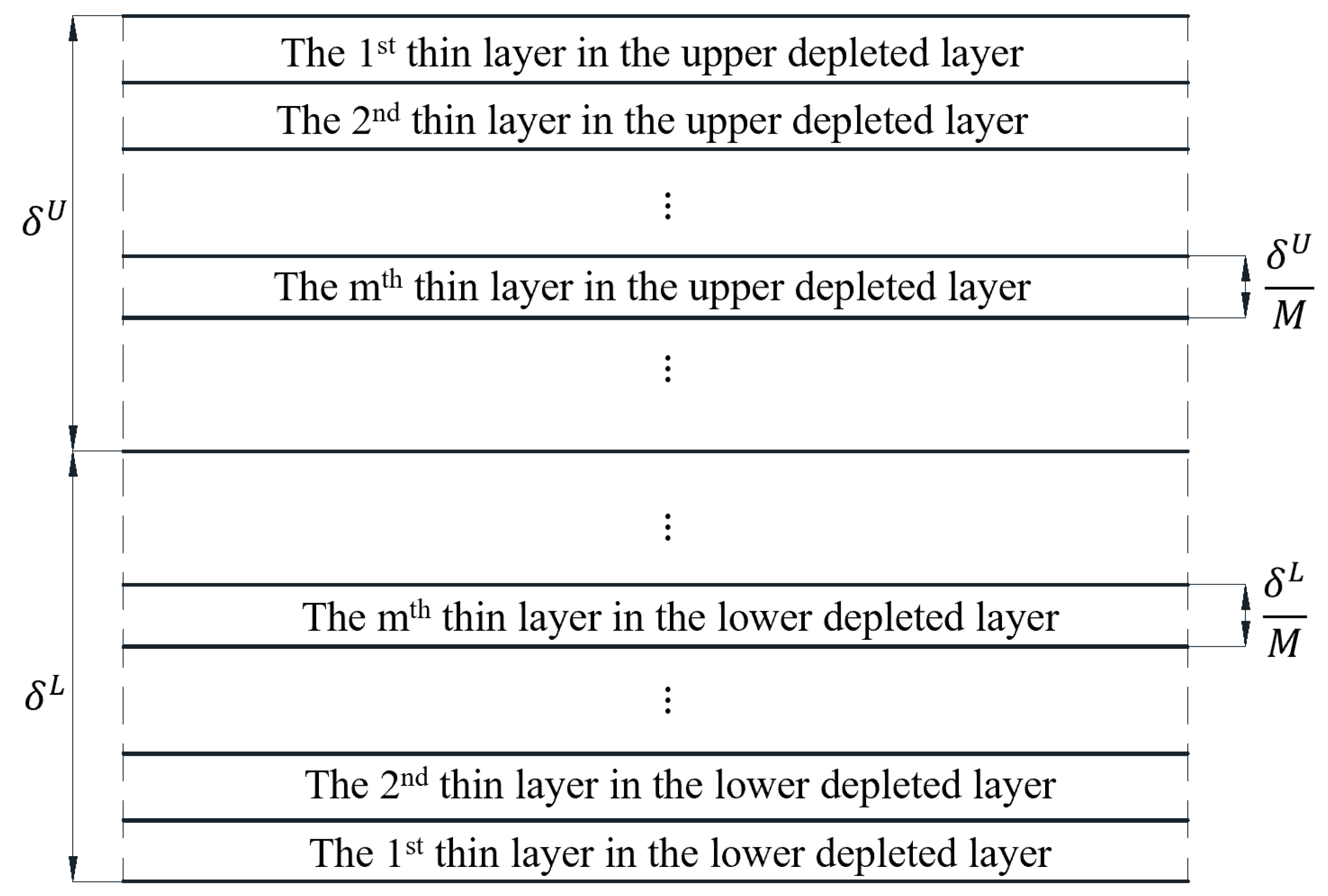
To obtain the transfer matrix of the homo- or hetero-junction, this functional gradient thin layer is evenly divided into a finite number of thin layers, as shown in Figure 2. The steady hole or electron carrier concentration in each thin layer can be treated as approximately homogeneous. Similar to the upper n-type PSC covering layer, the transfer matrix of the m t h thin layer in the lower depleted layer is
T m L = e x p δ L M W m L 1 H m L = Q m L e x p λ m 1 L δ L M 0 0 e x p λ m 8 L δ L M Q m L 1
where m = 1,2 , , M and
W m L = c z r z r L 0 0 c z z z z L 0 e z z z L 0 0 0 c r r z z L k r L H 0 k r L r H 0 k r L r c z r z r L k r L H 1 k r L r H 1 k r L r + 1 r 0 e r z r L k r L H 1 k r L r H 1 k r L r + 1 r 0 0 0
0 0 0 0 0 0 e z z z L 0 0 0 0 0 ε z z L 0 0 0 0 0 q p ¯ L h + M m M δ L μ z z p L q d z z p L 0 0 0 0 e z r r L k r L H 0 k r L r H 0 k r L r 0 1 0 0 0 0 0 0 1 0 0 0 0 0 0 1 0 0 0 0 0 0 1
H m L = 0 c z r z r L k r L H 0 k r L r H 0 k r L r c z z r r L k r L H 1 k r L r H 1 k r L r + 1 r 0 e z r r L k r L H 1 k r L r H 1 k r L r + 1 r 0 0 0 k r L 2 c r r r r L ρ L ω L 2 0 0 c z r z r L k r L 2 ρ L ω L 2 0 e r z r L k r L 2 0 0
e r z r L k r L H 0 k r L r H 0 k r L r 0 1 0 0 0 0 0 0 1 0 0 0 0 0 0 1 0 0 0 0 0 0 1 0 0 0 0 0 0 e r z r L k r L 2 0 0 0 0 0 ε r r L k r L 2 q 0 0 0 0 q p ¯ L h + M m M δ L μ r r p L k r L 2 q d r r p L k r L 2 + i ω L q 0 0 0 0
Q m L is the eigenvector matrix of the matrix W m L 1 H m L ; λ m L is the eigenvalue of the matrix W m L 1 H m L . The transfer matrix of the m t h thin layer in the upper depleted layer is
T m U = e x p δ U M W m U 1 H m U = Q m U e x p λ m 1 U δ U M 0 0 e x p λ m 8 U δ U M Q m U 1
where m = 1,2 , , M and
W m U = c z r z r U 0 0 c z z z z U 0 e z z z U 0 0 0 c r r z z U k r U H 0 k r U r H 0 k r U r c z r z r U k r U H 1 k r U r H 1 k r U r + 1 r 0 e r z r U k r U H 1 k r U r H 1 k r U r + 1 r 0 0 0
0 0 0 0 0 0 e z z z U 0 0 0 0 0 ε z z U 0 0 0 0 0 q n ¯ U h + M m M δ U μ z z n U q d z z n U 0 0 0 0 e z r r U k r U H 0 k r U r H 0 k r U r 0 1 0 0 0 0 0 0 1 0 0 0 0 0 0 1 0 0 0 0 0 0 1
H m U = 0 c z r z r U k r U H 0 k r U r H 0 k r U r c z z r r U k r U H 1 k r U r H 1 k r U r + 1 r 0 e z r r U k r U H 1 k r U r H 1 k r U r + 1 r 0 0 0 k r U 2 c r r r r U ρ U ω U 2 0 0 c z r z r U k r U 2 ρ U ω U 2 0 e r z r U k r U 2 0 0
e r z r U k r U H 0 k r U r H 0 k r U r 0 1 0 0 0 0 0 0 1 0 0 0 0 0 0 1 0 0 0 0 0 0 1 0 0 0 0 0 0 e r z r U k r U 2 0 0 0 0 0 ε r r U k r U 2 q 0 0 0 0 q n ¯ U h + M m M δ U μ r r n U k r U 2 q d r r n U k r U 2 i ω U q 0 0 0 0
Q m U is the eigenvector matrix of the matrix W m U 1 H m U ; λ m U is the eigenvalue of the matrix W m U 1 H m U . Therefore, the state vector function in the lower p-type PSC substrate at the interface z = h + is
V L r , h + , t = T M L T 2 L T 1 L T L U ϕ 1 L e x p i k z 1 L h + δ L , U ϕ 2 L e x p i k z 2 L h + δ L ,
U ϕ 3 L e x p i k z 3 L h + δ L , U ϕ 4 L e x p i k z 4 L h + δ L T H 0 k r L r e x p i ω L t 0 < r <
The state vector function in the upper n-type PSC covering layer at the interface z = h is
T M U T 2 U T 1 U T U h δ U V U r , 0 + , t = V U r , h , t
Consider that these two depleted layers are perfectly connected
u r U , u z U , ϕ U , n U , σ r z U , σ z z U , D z U , J z n U T z = h = u r L , u z L , ϕ L , p L , σ r z L , σ z z L , D z L , J z p L T z = h +
Inserting Equations (23) and (31) into Equation (71) leads to
V U r , h , t = V L r , h + , t
Inserting Equations (69) and (70) into Equation (72) leads to
V U r , 0 + , t = T ~ U 1 T ~ L U ϕ 1 L e x p i k z 1 L h + δ L , U ϕ 2 L e x p i k z 2 L h + δ L ,
U ϕ 3 L e x p i k z 3 L h + δ L , U ϕ 4 L e x p i k z 4 L h + δ L T H 0 k r L r e x p i ω L t 0 < r <
where T ~ U = T M U T 2 U T 1 U T U h δ U and T ~ L = T M L T 2 L T 1 L T L . Inserting Equation (73) into Equation (16) leads to
T ~ 0 U T ~ U 1 T ~ L U ϕ 1 L e x p i k z 1 L h + δ L , U ϕ 2 L e x p i k z 2 L h + δ L , U ϕ 3 L e x p i k z 3 L h + δ L ,
U ϕ 4 L e x p i k z 4 L h + δ L T H 0 k r L r e x p i ω L t = 0,0 , 0,0 T 0 < r <
where T ~ 0 U is the amendatory transfer matrix of the top surface
T ~ 0 U = 0 0 0 1 0 0 0 0 0 0 0 0 1 0 0 0 0 0 0 0 0 1 0 0 0 0 i ω U ε z z 0 k r U 0 0 0 1 0
Due to the existence of an untrivial solution, the following equation can be obtained
T ~ 0 U T ~ U 1 T ~ L = 0
Equation (76) is the dispersion equation of radially propagated cylindrical SAW obtained from the second mathematical model, in which there is no interface characteristic length. Considering these two mathematical models are equivalent, the interface characteristic lengths in the first mathematical model can be inversely confirmed through the comparison of dispersion and attenuation curves numerically calculated using these two mathematical models in the next section.

4. Numerical Results and Discussion

Since the dispersion and attenuation characteristics of SAW are closely related to the practical application of PSC materials, this section numerically calculates and discusses the dispersion and attenuation curves of radially propagated cylindrical SAW in the PSC semi-infinite medium through the two mathematical models established in Section 3.1 and Section 3.2. The horizontal coordinates of the dispersion and attenuation curves are also logarithmic frequencies f = ω / 2 π . The ordinates of the dispersion and attenuation curves are the radial wave speed c r = r e a l ω k r 1 and dimensionless attenuation coefficient k ¯ r = i m a g k r h , respectively. Meanwhile, the interface characteristic lengths are legitimately confirmed through the comparison of dispersion and attenuation curves calculated through the two equivalent mathematical models. The thickness of the upper n-type PSC covering layer is h = 10   μ m . Considering the difference in doping modes and concentrations, the upper covering layer and lower substrate are defined as an n-type ZnO PSC and p-type ZnO PSC, respectively, or an n-type GaN and p-type GaN PSC, respectively. The constitutive parameters of these two PSCs in the Cartesian coordinate system at 300 K are presented in Table 1 [31,40]. The mathematical relationship between the constitutive parameters in Table 1 and the constitutive parameters in Equations (6)–(8) is given as follows:
c r r r r = c 11 , c z z z z = c 33 , c r r z z = c z z r r = c 13 , c z r z r = c 44 , e r z r = e 15 , e z r r = e 31 ,
e z z z = e 33 , ε r r = ε 11 , ε z z = ε 33 , μ r r p = μ 11 p , μ z z p = μ 33 p , d r r p = d 11 p , d z z p = d 33 p ,
μ r r n = μ 11 n , μ z z n = μ 33 n , d r r n = d 11 n , d z z n = d 33 n
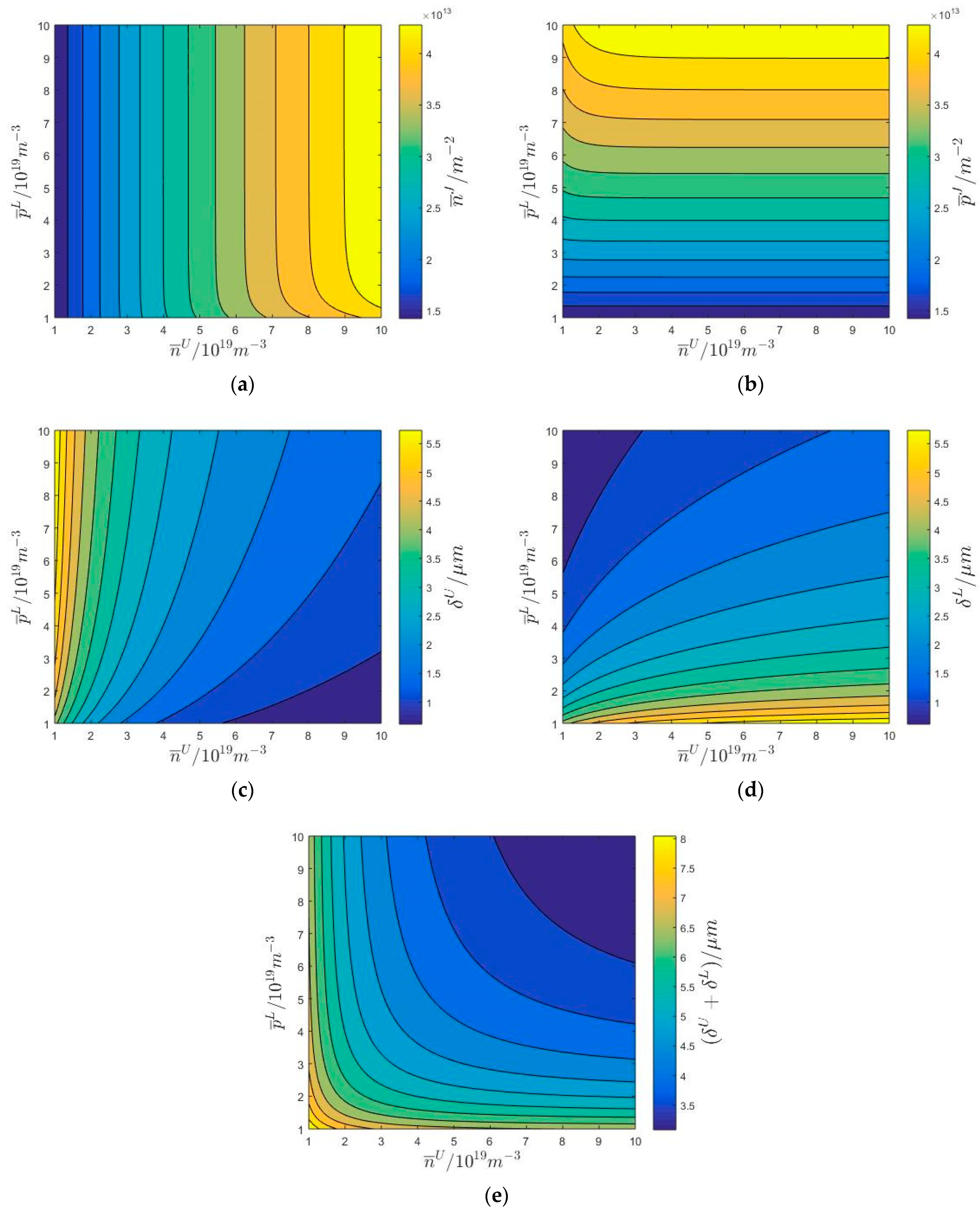
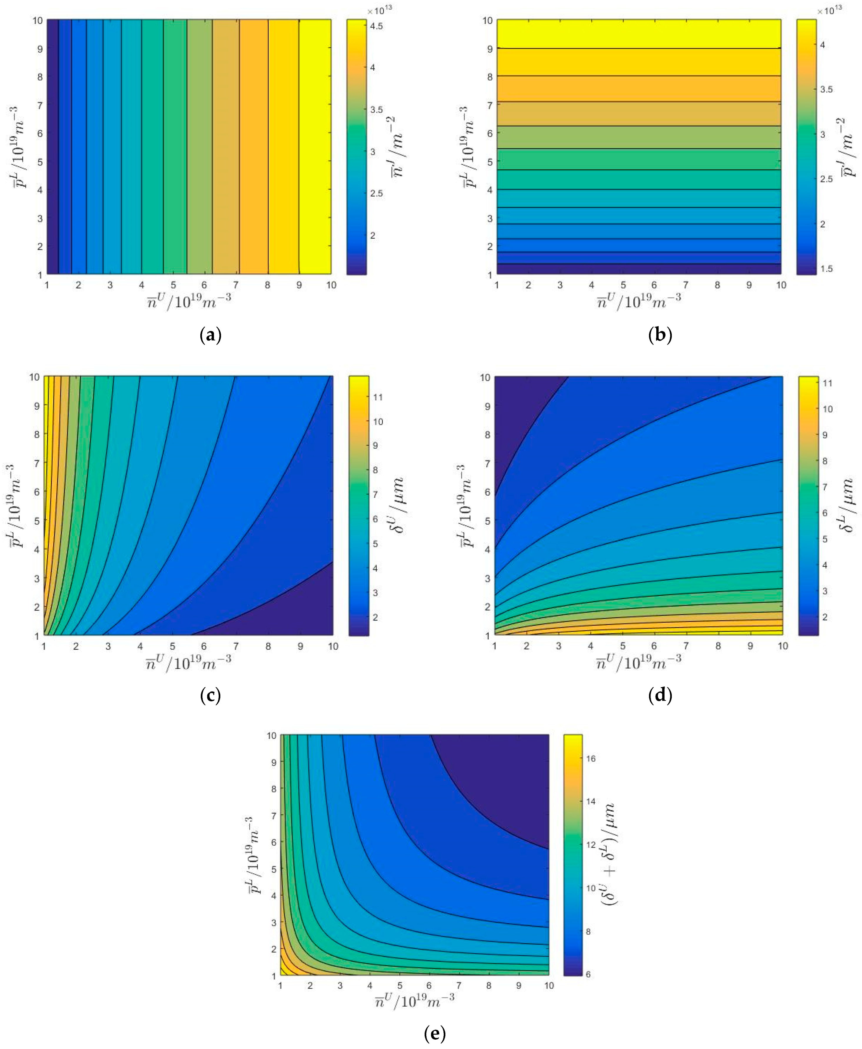
Figure 3 shows the numerical values of n ¯ J , p ¯ J , δ U , δ L , and δ U + δ L with the variation of doping concentrations n ¯ U and p ¯ L in the upper n-type ZnO/lower p-type ZnO semi-infinite medium. The elastic, piezoelectric, and dielectric characteristics of the ZnO semi-infinite medium are homogeneous. However, the carrier types between the upper covering layer and lower substrate differ. The numerical distributions of n ¯ J and p ¯ J in Figure 3a,b are approximately symmetrical with respect to the line n ¯ U = p ¯ L ; the numerical distributions of δ U and δ L in Figure 3c,d are approximately symmetrical with respect to the line n ¯ U = p ¯ L ; and the numerical distribution of δ U + δ L in Figure 3e is also approximately symmetrical with respect to the line n ¯ U = p ¯ L . This is because when n ¯ U = p ¯ L , the migration and diffusion of hole and electron carriers are approximatively identical in the upper and lower depleted layers in the homo-junction. It is further observed that the numerical value of δ U gradually decreases with the increase in n ¯ U . Similarly, the numerical value of δ L gradually decreases with the increase in p ¯ L ; the minimum value of δ U + δ L occurs when the numerical values of n ¯ U and p ¯ L reach the maximum, i.e., n ¯ U = p ¯ L = 10 19 m 3 . These numerical results mean that the increase in n ¯ U and p ¯ L can make the homo-junction more like an electrically imperfect interface. Why? This is because the electric potential difference between the upper and lower boundaries of homo-junction ϕ increases with the increase in n ¯ U and p ¯ L , as shown in Equation (A7), which restrains the migration and diffusion of hole and electron carriers in the lower and upper depleted layers. Since the numerical magnitudes of δ U and δ L are on the order of microns, the numerical values of p ¯ J and n ¯ J are also much lower than that of doping concentrations in the upper and lower PSC regions. It is further observed that the numerical value of n ¯ J monotonously increases with the increase in n ¯ U ; the numerical value of p ¯ J also monotonously increases with the increase in p ¯ L . These numerical results mean that the increase in n ¯ U and p ¯ L can not only make the homo-junction more like an electrically imperfect interface but also enhance the semiconductor effect of the homo-junction. Therefore, the homo-junction or hetero-junction is treated as a two-dimensional electrically imperfect interface in the first mathematical model established in Section 3.1.
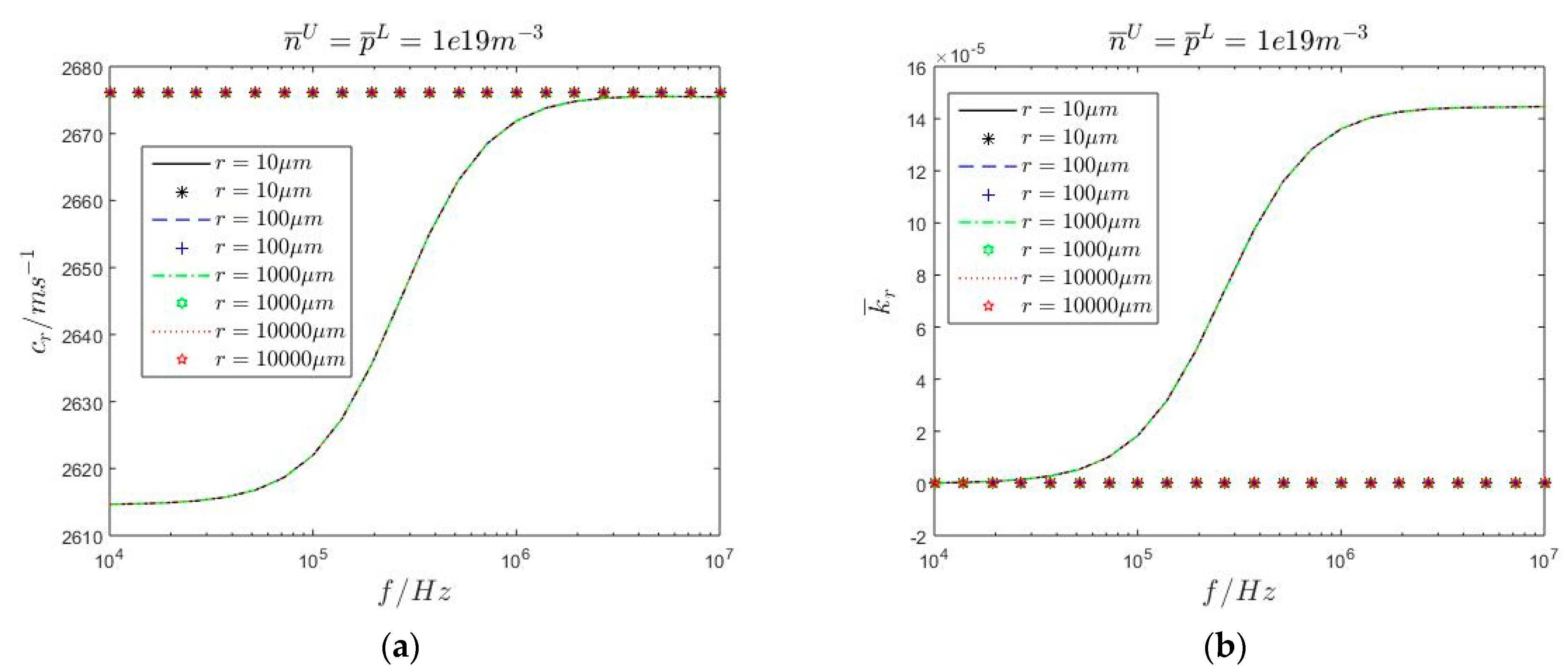
Figure 4 shows the dispersion and attenuation curves of radially propagated cylindrical SAW in the upper n-type ZnO/lower p-type ZnO semi-infinite medium with the variation of the r coordinate when n ¯ U = p ¯ L = 1 × 10 19 m 3 . Both the continuous curves and the discrete numerical points are calculated using the second mathematical model established in Section 3.2. In calculating the continuous lines, the semiconductor effect is considered, while in calculating the discrete numerical points, the semiconductor effect is not considered, i.e., the piezoelectric ZnO semi-infinite medium. Compared with the discrete numerical points, it is observed from Figure 4b that the radial wave number component k r is complex-valued with the consideration of the semiconductor effect. This means that radially propagated cylindrical SAW decays along the depth direction of the semi-infinite medium (the positive direction of the z-axis) and the propagation direction (the positive direction of the r-axis). This propagation characteristic of SAW does not exist in the piezoelectric dielectric semi-infinite, which can be utilized to optimize the acoustic characteristics of energy harvesters formed by PSC semi-infinite medium. When f < 50   K H z , the wave speeds of radially propagated cylindrical SAW are 2615   m / s and the numerical values of k ¯ r are constants, approximately. This is because the wavelengths of radially propagated cylindrical SAW are much larger than the geometrical thickness of the upper n-type ZnO covering layer, and the wave motion energy of radially propagated cylindrical SAW is mainly concentrated on the lower p-type ZnO substrate. As a result of the migration and diffusion of hole and electron carriers and the existence of hole and electron carrier current densities, the wave speed of radially propagated cylindrical SAW in the lower p-type ZnO substrate is lower than that in the piezoelectric ZnO substrate, which is approximately 2676.19 m/s. With the increase in f , the wave speeds of radially propagated cylindrical SAW and the numerical values of k ¯ r grow gradually. When f > 5   M H z , the wave speeds of radially propagated cylindrical SAW are 2675.5   m / s and the numerical values of k ¯ r are approximately constant. This is because the wavelengths of radially propagated cylindrical SAW are much smaller than the geometrical thickness of the upper n-type ZnO covering layer, and the wave motion energy of radially propagated cylindrical SAW is mainly concentrated on the upper n-type ZnO covering layer. Therefore, 50   K H z f 5   M H z is the frequency interval where the semiconductor effect is obvious at such doping concentrations. Compared with the p-type ZnO lower substrate, the wave speed of radially propagated cylindrical SAW in the upper n-type ZnO covering layer is much closer to that in the piezoelectric ZnO semi-infinite medium. Why? This is because k = 2 in Equation (8) for the upper n-type ZnO covering layer, which means that the current generated by the diffusion motion of the electron carriers is offset by the current generated by the migration motion of the electron carriers. The semiconductor effect in the upper n-type ZnO covering layer is weaker than that in the lower p-type ZnO substrate. It is further observed that the dispersion and attenuation curves of radially propagated cylindrical SAW are independent of the r coordinate, which means that the dispersion and attenuation characteristics discussed in this section apply to cylindrical SAW radially propagating anywhere in the PSC semi-infinite medium.
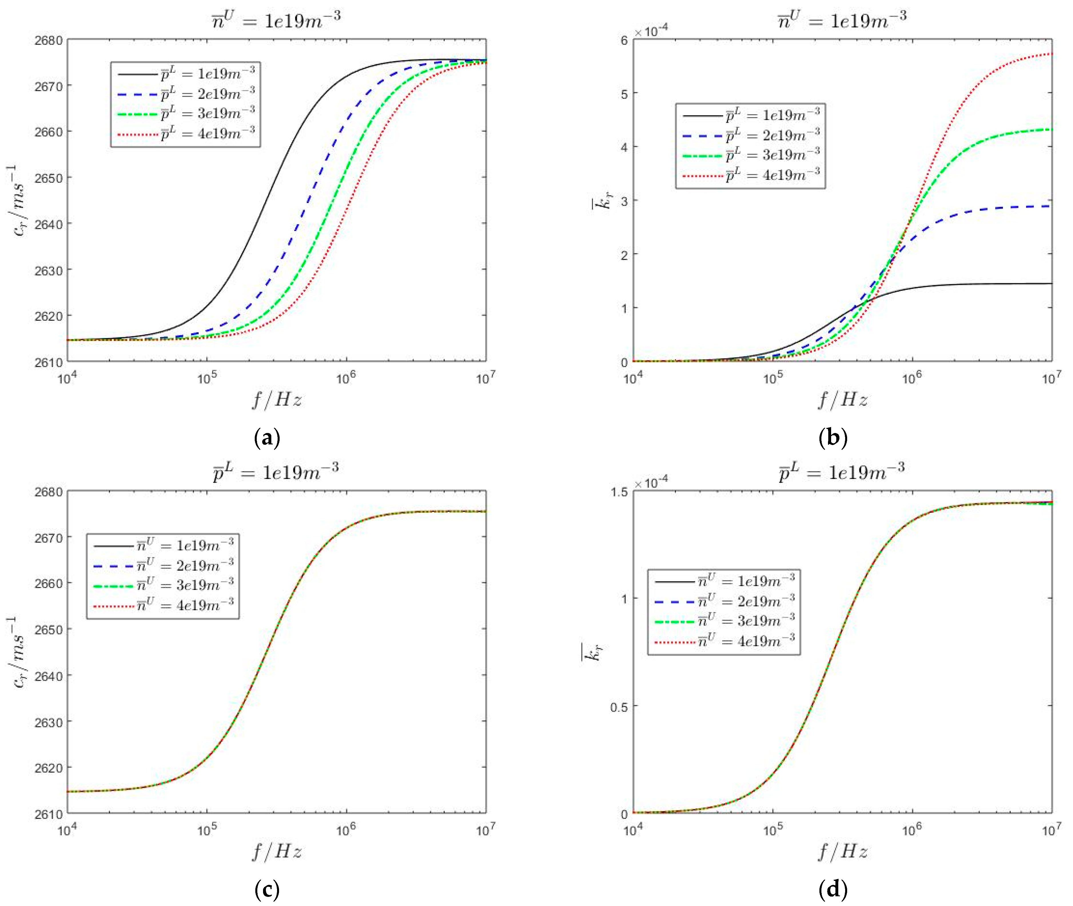
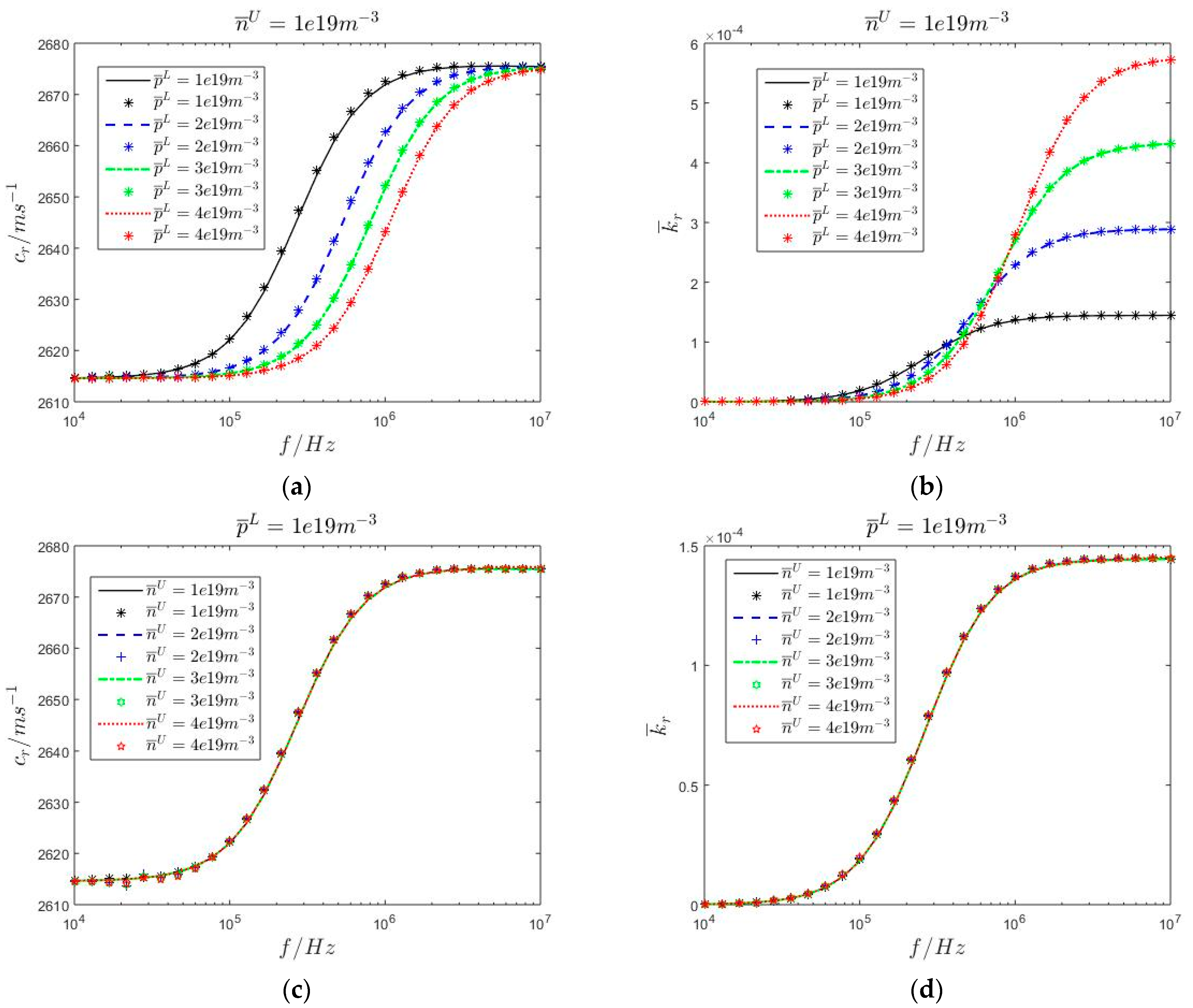
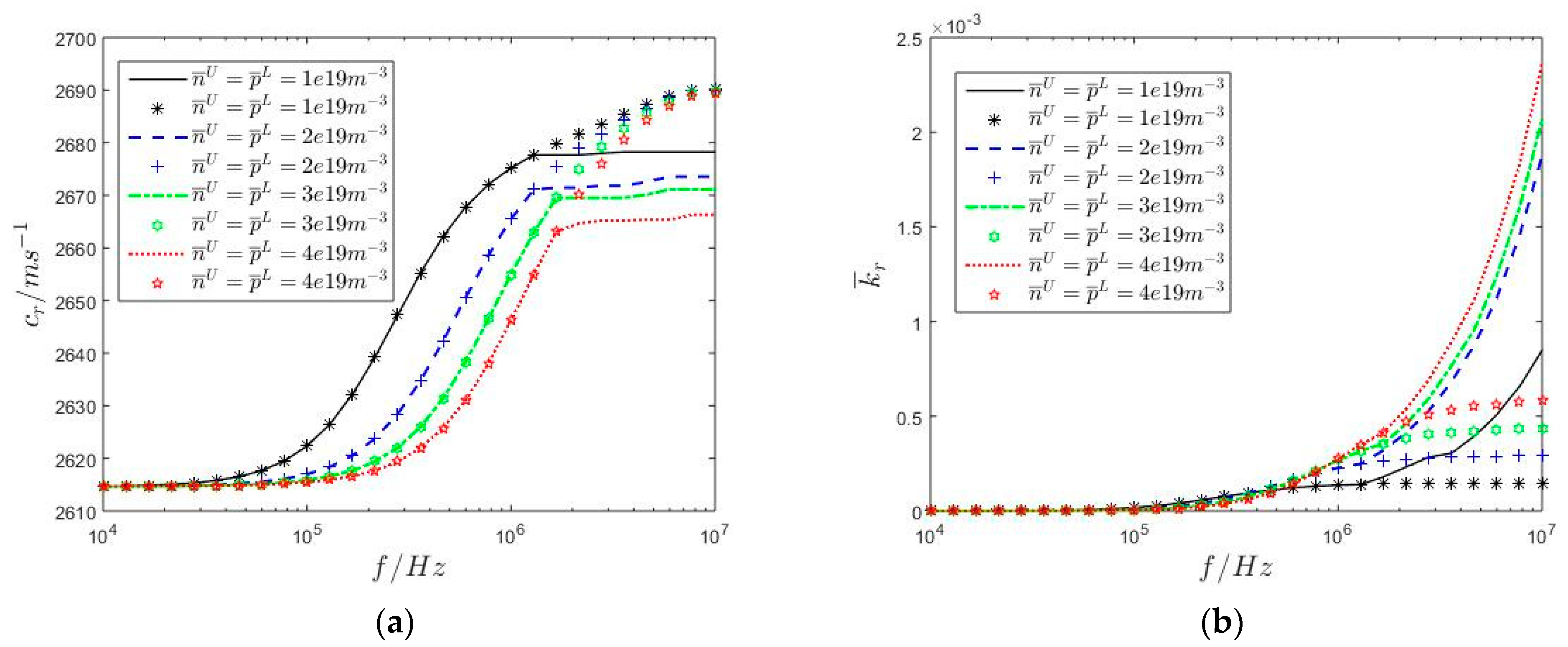
Figure 5 shows the dispersion and attenuation curves of radially propagated cylindrical SAW in the upper n-type ZnO/lower p-type ZnO semi-infinite medium with the variation of doping concentrations calculated using the second mathematical model established in Section 3.2. Compared with the dispersion curves shown in Figure 4a, Figure 5a shows that the increase in p ¯ L causes the dispersion curves to shift toward lower wave speeds. The larger the amplitude of p ¯ L , the more evident the dispersion curve shift. This is because the increase in p ¯ L can raise the hole carrier current densities and enhance the efficiency of energy conversion from mechanical energy to electrical energy resulting from the semiconductor effect, according to Equation (8). Therefore, the larger the amplitude of p ¯ L , the more evident the shift in the attenuation curve, as shown in Figure 5b. The attenuation curves of radially propagated cylindrical SAW are not closer when f 10 7   H z . This means that radially propagated cylindrical SAW exhibits stable attenuation characteristics resulting from the migration and diffusion of electron carriers. The larger the amplitude of p ¯ L , the more evident the attenuation characteristic. Compared with Figure 5a,b, Figure 5c,d shows that the increase in n ¯ U has little influence on the dispersion and attenuation curves of radially propagated cylindrical SAW. This is also because the semiconductor effect in the upper n-type ZnO covering layer is weaker than that in the lower p-type ZnO substrate.
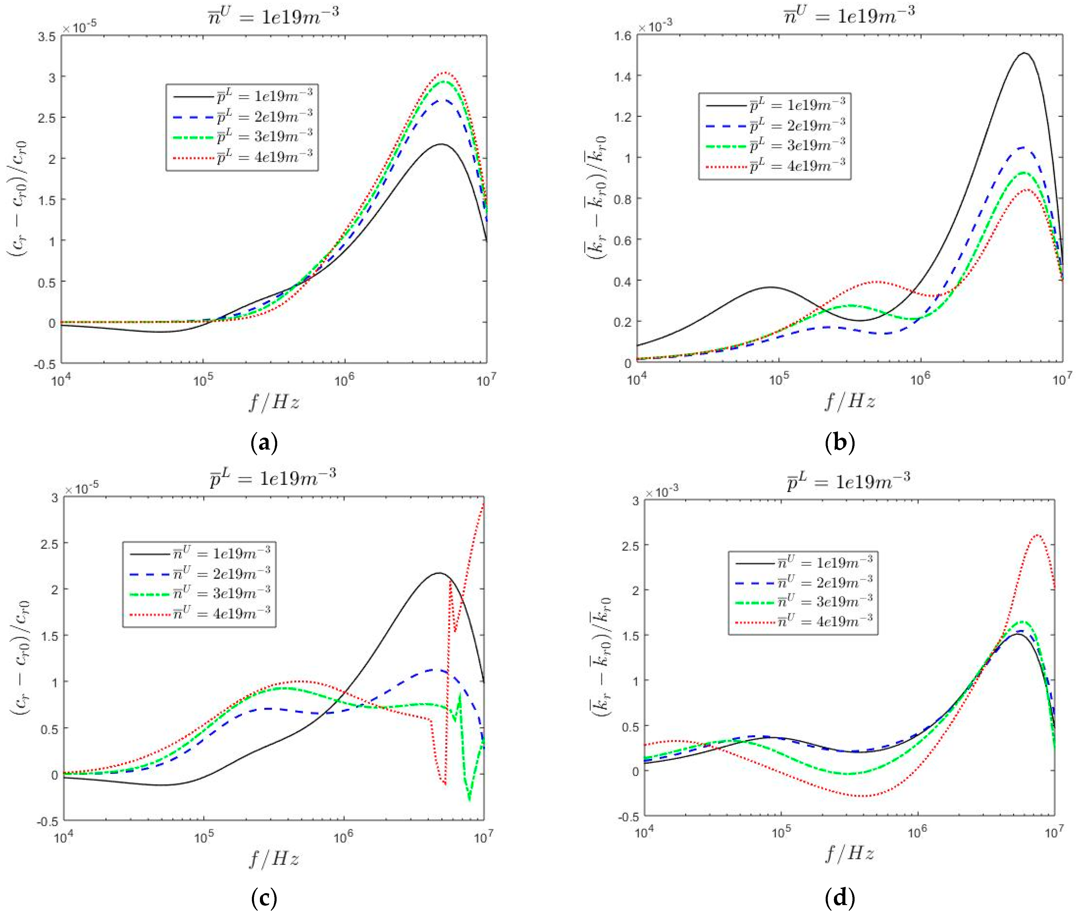
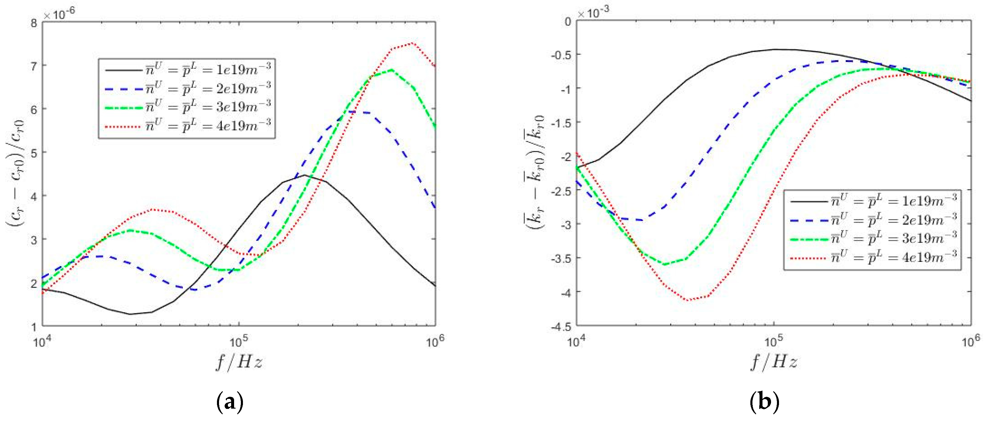
The radial wave speed c r 0 and the dimensionless attenuation coefficient k ¯ r 0 are calculated without considering the homo-junction in the upper n-type ZnO/lower p-type ZnO semi-infinite medium using the second mathematical model established in Section 3.2. When considering the homo-junction, Figure 6 shows the relative changes of the two wave motion quantities of radially propagated cylindrical SAW in the upper n-type ZnO/lower p-type ZnO semi-infinite medium with varying doping concentrations. Since the physical properties of the homo-junction, including the steady hole and electron charge carrier concentrations, and the thicknesses are closely related to the semiconductor effect in the upper n-type ZnO/lower p-type ZnO semi-infinite medium, Figure 6 shows that the homo-junction has more evident influence on the attenuation curves than the dispersion curves. The larger the amplitude of p ¯ L or n ¯ U , the greater the influence of the homo-junction. Compared with the variation of p ¯ L , that of n ¯ U can increase the influence of the homo-junction, especially for the high-frequency dispersion and attenuation curves. Why? This is because the migration and diffusion of hole and electron carriers in the upper n-type ZnO/lower p-type ZnO semi-infinite medium is closely related to the frequency, as shown in Equation (9). Table 1 shows that the numerical values of μ i j p and d i j p are much lower than those of μ i j n and d i j n . Therefore, the hole carrier in the lower p-type ZnO substrate can be regarded as a heavy particle sensitive to low-frequency wave motion, while the electron carrier in the lower n-type ZnO substrate can be regarded as a light particle sensitive to high-frequency wave motion.
Figure 7 shows the numerical comparison of the dispersion and attenuation curves of radially propagated cylindrical SAW in the upper n-type ZnO/lower p-type ZnO semi-infinite medium calculated by the two equivalent mathematical models. The continuous curves are calculated using the second mathematical model established in Section 3.2. Meanwhile, the discrete numerical points are calculated using the first mathematical model established in Section 3.1, in which the interface characteristic lengths related to the interface dielectric parameter and semiconductor effect of the homo-junction are:
f ε U = f ε L = 277.994144 m , f n U = 56.658272 m , f p L = 162.221387 m
As these two mathematical models are equivalent, all discrete numerical points fall approximately on the continuous curves. Since the dielectric characteristic of the ZnO semi-infinite medium is homogeneous, the interface characteristic lengths related to the interface dielectric parameters are identical, i.e., f ε U = f ε L ; while since the carrier types between the upper and lower depleted layers differ, the interface characteristic lengths related to the interface semiconductor effect differ, i.e., f n U f p L . Since the semiconductor effect in the upper n-type ZnO covering layer is weaker than that in the lower p-type ZnO substrate, f n U < f p L , indicating that the lower depleted layer makes a greater contribution to the homo-junction than the upper depleted layer.
Figure 8 shows the numerical values of n ¯ J , p ¯ J , δ U , δ L , and δ U + δ L with the variation of doping concentrations n ¯ U and p ¯ L in the upper n-type GaN/lower p-type ZnO semi-infinite medium. The carrier types between the upper covering layer and substrate differ, and the elastic, piezoelectric, and dielectric characteristics of the semi-infinite medium are inhomogeneous, as shown in Table 1. Therefore, the migration and diffusion of hole and electron carriers in the upper and lower depleted layers are more vigorous. The numerical values of n ¯ J , p ¯ J , δ U , δ L , and δ U + δ L in the upper n-type GaN/lower p-type ZnO semi-infinite medium are larger than that in the upper n-type ZnO/lower p-type ZnO semi-infinite medium. It is necessary to discuss the influence of the hetero-junction on the dispersion and attenuation curves of radially propagated cylindrical SAW in the upper n-type GaN/lower p-type semi-infinite medium.
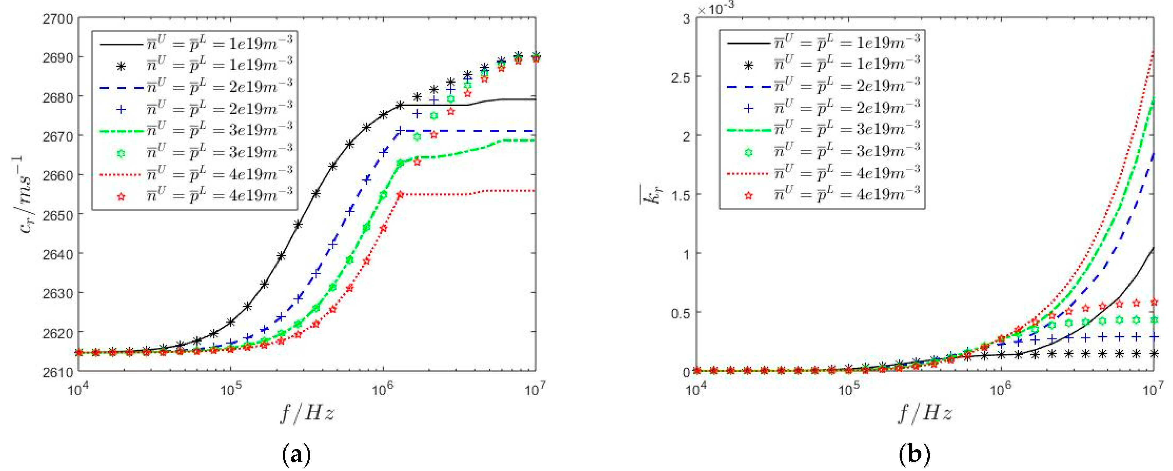
Figure 9 shows the dispersion and attenuation curves of radially propagated cylindrical SAW in the upper n-type GaN/lower p-type ZnO semi-infinite medium with varying doping concentrations calculated using the second mathematical model established in Section 3.2. The continuous curves are calculated considering the hetero-junction, while the discrete numerical points are calculated without considering the hetero-junction. Since the semiconductor effect is closely related to the frequency, all discrete numerical points approximately fall on the continuous curves when f < 1   M H z ; while with a further increase in f , the differences between the continuous curves and discrete numerical points become more evident, meaning that the calculation error of the second mathematical model becomes increasingly obvious.
Figure 10 shows the relative changes of the radial wave speed c r c r 0 / c r 0 and the dimensionless attenuation coefficient k r 0 k ¯ r 0 / k ¯ r 0 of radially propagated cylindrical SAW in the upper n-type GaN/lower p-type ZnO semi-infinite medium with varying doping concentrations. The frequency is calculated within the 10   K H z f 1   M H z interval. Since the steady charge carrier concentrations and geometrical thicknesses of the hetero-junction are larger than that of the homo-junction, the overall numerical values of the two wave motion quantities in Figure 10 are larger than that in Figure 6.
Figure 11 shows the numerical comparations of the dispersion and attenuation curves of radially propagated cylindrical SAW in the upper n-type GaN/lower p-type ZnO semi-infinite medium calculated by the two equivalent mathematical models. Similarly, the discrete numerical points and the continuous curves for each doping concentration are calculated using the first and second mathematical models established in Section 3.1 and Section 3.2, respectively, in which the interface characteristic lengths related to the interface dielectric parameter and semiconductor effect of the hetero-junction are
f ε U = 2852.449525 m , f ε L = 2347.338294 m ,
f n U = 255.0253663 m , f p L = 0.552097863 m
Since the steady charge carrier concentrations and geometrical thicknesses of the hetero-junction are larger than that of the homo-junction, most of the interface characteristic lengths of the hetero-junction are much larger than that of the homo-junction. The interface characteristic lengths related to the interface dielectric parameters f ε U and f ε L are positive, while those related to the interface semiconductor effect f n U and f p L are negative. This can be explained by Equation (48): the interface effect resulting from the hetero-junction leads to the discontinuities of the electric displacement and the hole and electron carrier current density. Therefore, the above quantities on both sides of the interface have jump values, which can be positive or negative. Compared with Figure 7, the discrete numerical points fall approximately on the continuous curves when f < 1   M H z in Figure 11; while with a further increase in f , the differences between the continuous curves and discrete numerical points are increasingly evident, which also means that the calculation error of the second mathematical model is more obvious.

5. Concluding Remarks

The influence of the homo- and hetero-junctions on the dispersion and attenuation characteristics of radially propagated cylindrical SAW in the PSC semi-infinite medium is the primary focus of the present work. As the numerical distributions of the steady hole and electron carrier concentrations in the homo- and hetero-junctions are inhomogeneous, they can be treated as functional gradient thin layers. Considering their thicknesses are much smaller than those of the upper covering layer, they also can be approximately treated as two-dimensional electrically imperfect interfaces without geometrical thickness but with physical dielectric and semiconductor characteristics. Through these two equivalent mathematical models, the dispersion and attenuation curves of radially propagated cylindrical SAW are numerically calculated and discussed. The interface characteristic lengths are confirmed by comparing the dispersion and attenuation curves calculated using the two equivalent mathematical models, which is the novelty of this paper. From the numerical results, the following conclusions can be drawn:
  • The physical properties of the homo- and hetero-junctions are closely related to the doping modes and concentrations in the PSC semi-infinite medium, of which the increase not only makes the homo- and hetero-junctions more like electrically imperfect interfaces but also enhance the influence of the homo- and hetero-junctions.
  • The influence of the homo- and hetero-junctions on the dispersion and attenuation characteristics of radially propagated cylindrical SAW is closely related to the angular frequency. It is of great significance to consider the existence of homo- and hetero-junctions when studying the propagation of high-frequency SAW in PSC materials.
  • The homo- and hetero-junctions can enhance the conversion efficiency from mechanical to electrical energy; adjusting doping modes and concentrations of PSC semi-infinite medium can regulate attenuation characteristics of cylindrical SAW and optimize the acoustic characteristics of SAW resonators, energy harvesters, and acoustic wave amplification formed by PSC semi-infinite medium.
  • Since the dispersion and attenuation characteristics of cylindrical SAW are independent of the radial coordinate, the mathematical models in this paper provide theoretical guidance for studying the propagation characteristics of other types of SAW in PSC materials, such as the Rayleigh-type SAW. Since the influence of the homo- and hetero-junctions mainly concentrates on the attenuation characteristic of SAW, the discussion in this paper provides theoretical guidance for the design and manufacture of SAW resonators [3,4], energy harvesting [6,7], and acoustic wave amplification [8]. Due to the interface characteristic lengths, the first mathematical model is more complex than the second. The homo- and hetero-junctions are treated as functional gradient thin layers; the second mathematical model is more accurate than the first. Based on Figure 9 and Figure 11, the computational stability of the second mathematical model is weaker than that of the first. Considering the interface characteristic lengths are independent of the doping concentrations, the first mathematical model is more practical in studying wave motion problems. Based on Figure 6 and Figure 10, the relative changes of the radial wave speed and dimensionless attenuation coefficient are considerably lower than 1, which means that the homo- and hetero-junctions have less evident influence on the propagation characteristics of low-frequency radially propagated cylindrical SAW. Therefore, in subsequent work, we must establish a simpler mathematical model with better computational accuracy and stability to study the propagation characteristics of high-frequency SAW in the PSC materials, such as the PSC layered composite structures containing multi-layer homo- and hetero-junctions.

Author Contributions

Conceptualization, X.G.; methodology, X.G.; software, X.G.; validation, X.G.; formal analysis, Y.W.; investigation, Y.W.; resources, C.X.; data curation, C.X.; writing—original draft preparation, Z.W.; writing—review and editing, Z.W.; visualization, C.D.; supervision, C.D.; All authors have read and agreed to the published version of the manuscript.

Funding

This research was funded by National Natural Science Foundation of China, grant number 12202039 and Interdisciplinary Research Project for Young Teachers of USTB (Fundamental Research Funds for the Central Universities), grant number FRF-IDRY-21-006.

Data Availability Statement

The data that support the findings of this study are available on request from the corresponding author, Xiao Guo ([email protected]), upon reasonable request.

Conflicts of Interest

The authors declare that they have no conflicts of interest in this work. The authors declare that they do not have any commercial or associative interest that represents a conflict of interest in connection with the work submitted.

Appendix A

Consider the upper PSC covering layer and lower PSC substrate are n-type and p-type PSC, respectively. The perturbation of the hole or electron carrier concentration is zero before the propagation of radially propagated cylindrical SAW. Therefore, the upper n-type PSC covering layer and lower p-type PSC substrate are electrically neutral [23,31]:
n ¯ U z + n D U = 0 0 z h δ U
p ¯ L z p A L = 0 h + δ L z <
where p A L and n D U are acceptor and donor concentrations in the lower p-type PSC substrate and upper n-type PSC covering layer, respectively. The steady hole and electron carrier concentrations are [23,31]
n ¯ U z = n i U e x p μ z z n U ϕ U d z z n U 0 z h δ U
p ¯ L z = n i L e x p μ z z p L ϕ L d z z p L h + δ L z <
Inserting Equations (A3) and (A4) into (A1) and (A2) leads to the electric potential
ϕ U z = d z z n U μ z z n U l n n D U n i U 0 z h δ U
ϕ L z = d z z p L μ z z p L l n p A L n i L h + δ L z <
where d z z p L / μ z z p L = d z z n U / μ z z n U , as shown in Table 1. According to Equations (A5) and (A6), the electric potential difference between the upper p-type PSC covering layer and lower n-type PSC substrate is
ϕ = ϕ L h + δ L ϕ U h δ U = d z z p L μ z z p L l n p A L n D U n i U n i L
before the propagation of cylindrical SAW, the normal electric displacements are
D z U z = ε z z U ϕ , z U z h δ U z h
D z L z = ε z z L ϕ , z L z h z h + δ L
According to Gauss’s law of electrostatics [23,31], the gradients of normal electric displacements are
D z , z U z = q n ¯ U z + n D U q n D U z h δ U z h
D z , z L z = q p ¯ L z p A L q p A L z h z h + δ L
Consider the continuity of the normal electric field at the boundaries z = h δ U and z = h + δ L
E z U h δ U = ϕ , z U h δ U = 0
E z L h + δ L = ϕ , z L h + δ L = 0
Inserting Equations (A8), (A9), (A12), and (A13) into Equations (A10) and (A11) leads to
ϕ , z U z = q n D U ε z z U z h + δ U h δ U z h
ϕ , z L z = q p A L ε z z L z h δ L h z h + δ L
Therefore, the distribution of the electric potential is
ϕ U z = q n D U ε z z U 1 2 z h 2 + δ U z h + ϕ 0 h δ U z h
ϕ L z = q p A L ε z z L 1 2 z h 2 δ L z h + ϕ 0 h z h + δ L
where ϕ 0 is the electric potential at the boundary z = h . Considering the depletion layer hypothesis and the charge balance condition yields [23,31]
p A L δ L = n D U δ U
Inserting Equations (A16), (17), and (A18) into Equation (A7) leads to the geometrical thicknesses of these two depleted layers in Figure 1
δ U = 2 p A L ε z z L ε z z U d z z p L q n D U p A L ε z z L + n D U ε z z U μ z z p L l n p A L n D U n i L n i U
δ L = 2 ε z z L ε z z U n D U d z z p L q p A L p A L ε z z L + n D U ε z z U μ z z p L l n p A L n D U n i L n i U
Furthermore, the normal hole and electron current densities are zero before the propagation of cylindrical SAW
J z p U z = q n ¯ U μ z z n U ϕ , z U z + q d z z n U n ¯ , z U z = 0 h δ U z h
J z n L z = q p ¯ L μ z z p L ϕ , z L z q d z z p L p ¯ , z L z = 0 h z h + δ L
Inserting Equations (A1), (A2), (A14), and (A15) into Equations (A21) and (A22) leads to the distribution of steady hole and electron carrier concentration in Equation (1)
n ¯ U z = n D U 0 z h δ U n D U e x p q μ z z n U n D U ε z z U d z z n U 1 2 z h 2 + δ U z h + 1 2 δ U 2 h δ U z h
p ¯ L z = p A L e x p q μ z z p L p A L ε z z L d z z p L 1 2 z h 2 δ L z h + 1 2 δ L 2 h z h + δ L p A L h + δ L z <
Based on Equations (A23) and (A24), the steady hole and electron carrier concentrations are inhomogeneous in these two depleted layers. Therefore, the homo- or hetero-junction can be treated as one functional gradient thin layer. Considering δ U h and δ L , thetwo depleted layers can be approximately treated as a two-dimensional imperfect interface without geometrical thickness. Therefore, the interface steady hole and electron carrier concentrations in Equation (42) are
n ¯ J = h δ U h n ¯ U z d z
p ¯ J = h h + δ L p ¯ L z d z

References

  1. Patel, R.; Patel, M.; Boolchandani, D.; Rangra, K. FEM modeling of solidly mounted film bulk acoustic resonator and gas sensor using PIB-sensitive layer. J. Micro/Nanolithogr. MEMS MOEMS 2017, 16, 025002. [Google Scholar] [CrossRef]
  2. Wang, J.; Park, M.; Mertin, S.; Pensala, T.; Ayazi, F.; Ansari, A. A film bulk acoustic resonator based on ferroelectric aluminum scandium nitride films. J. Microelectromech. Syst. 2020, 29, 741–747. [Google Scholar] [CrossRef]
  3. Patel, R.; Adhikari, M.S.; Boolchandani, D. Active area optimisation of film bulk acoustic resonator for improving performance parameters. Electron. Lett. 2020, 56, 1191–1194. [Google Scholar] [CrossRef]
  4. Hu, Y.; Dong, B.; Lei, L.; Wang, Z.; Ruan, S. High-order harmonic film bulk acoustic resonator based on a polymer reflector. Sensors 2022, 22, 7439. [Google Scholar] [CrossRef] [PubMed]
  5. Lv, L.; Shuai, Y.; Bai, X.; Huang, S.; Zhu, D.; Wang, Y.; Zhao, J.; Luo, W.; Wu, C.; Zhang, W. wide band BAW filter based on single-crystalline linbo3; thin film with insulating bragg reflector. IEEE Trans. Ultrason. Ferroelectr. Freq. Control. 2022, 69, 1535–1541. [Google Scholar] [CrossRef] [PubMed]
  6. Kumar, B.; Kim, S.W. Energy harvesting based on semiconducting piezoelectric ZnO nanostructures. Nano Energy 2012, 1, 342–355. [Google Scholar] [CrossRef]
  7. Hiralal, P.; Unalan, H.E.; Amaratunga, G.A.J. Nanowires for energy generation. Nanotechnology 2012, 23, 194002. [Google Scholar] [CrossRef] [PubMed]
  8. Fan, J.C.; Sreekanth, K.M.; Xie, Z.; Chang, S.L.; Rao, K.V. P-type ZnO materials: Theory, growth, properties and devices. Prog. Mater. Sci. 2013, 58, 874–985. [Google Scholar] [CrossRef]
  9. Gurtin, M.E.; Ian Murdoch, A. A continuum theory of elastic material surfaces. Arch. Ration. Mech. Anal. 1975, 57, 291–323. [Google Scholar] [CrossRef]
  10. Murdoch, A.I. The propagation of surface waves in bodies with material boundaries. J. Mech. Phys. Solids 1976, 24, 137–146. [Google Scholar] [CrossRef]
  11. Gurtin, M.E.; Ian Murdoch, A. Surface stress in solids. Int. J. Solids Struct. 1978, 14, 431–440. [Google Scholar] [CrossRef]
  12. Chen, W. Surface effect on Bleustein-Gulyaev wave in a piezoelectric substrate. Theor. Appl. Mech. Lett. 2011, 1, 041001. [Google Scholar] [CrossRef]
  13. Zhang, L.L.; Liu, J.X.; Fang, X.Q.; Nie, G.Q. Effects of surface piezoelectricity and nonlocal scale on wave propagation in piezoelectric nanoplates. Eur. J. Mech.—A/Solids 2014, 46, 22–29. [Google Scholar] [CrossRef]
  14. Zhang, L.L.; Liu, J.X.; Fang, X.Q.; Nie, G.Q. Size-dependent dispersion characteristics in piezoelectric nanoplates with surface effects. Phys. E Low-Dimens. Syst. Nanostruct. 2014, 57, 169–174. [Google Scholar] [CrossRef]
  15. Zhang, S.; Gu, B.; Zhang, H.; Feng, X.Q.; Pan, R.; Alamusi; Hu, N. Propagation of Love waves with surface effects in an electrically-shorted piezoelectric nanofilm on a half-space elastic substrate. Ultrasonics 2016, 66, 65–71. [Google Scholar] [CrossRef] [PubMed]
  16. Zhang, L.L.; Zhao, J.; Liu, X.L.; Liu, J.X. Shear horizontal surface waves in piezoelectric materials with surface stress. Philos. Mag. Lett. 2018, 98, 350–357. [Google Scholar] [CrossRef]
  17. Enzevaee, C.; Shodja, H.M. Crystallography and surface effects on the propagation of Love and Rayleigh surface waves in fcc semi-infinite solids. Int. J. Solids Struct. 2018, 138, 109–117. [Google Scholar] [CrossRef]
  18. Qian, J.; Lia, C.; Qian, L.; Lia, M.; Li, H.; Yang, B. Three-dimensional finite element simulation of Love mode surface acoustic wave in layered structures including ZnO piezoelectric film and diamond substrate. Diam. Relat. Mater. 2018, 88, 123–128. [Google Scholar] [CrossRef]
  19. Zhu, F.; Pan, E.; Qian, Z.; Wang, Y. Dispersion curves, mode shapes, stresses and energies of SH and Lamb waves in layered elastic nanoplates with surface/interface effect. Int. J. Eng. Sci. 2019, 142, 170–184. [Google Scholar] [CrossRef]
  20. Wang, X.; Li, P.; Jin, F. A generalized dynamic model of nanoscale surface acoustic wave sensors and its applications in Love wave propagation and shear-horizontal vibration. Appl. Math. Model. 2019, 75, 101–115. [Google Scholar] [CrossRef]
  21. Zhang, Y.; Liu, Y.; Wang, Z.L. Fundamental Theory of Piezotronics. Adv. Mater. 2011, 23, 3004–3013. [Google Scholar] [CrossRef] [PubMed]
  22. Fan, S.; Liang, Y.; Xie, J.; Hu, Y. Exact solutions to the electromechanical quantities inside a statically-bent circular ZnO nanowire by taking into account both the piezoelectric property and the semiconducting performance: Part I–Linearized analysis. Nano Energy 2017, 40, 82–87. [Google Scholar] [CrossRef]
  23. Fan, S.; Yang, W.; Hu, Y. Adjustment and control on the fundamental characteristics of a piezoelectric PN junction by mechanical-loading. Nano Energy 2018, 52, 416–421. [Google Scholar] [CrossRef]
  24. Liang, Y.; Fan, S.; Chen, X.; Hu, Y. Nonlinear effect of carrier drift on the performance of an n-type ZnO nanowire nanogenerator by coupling piezoelectric effect and semiconduction. Beilstein J. Nanotechnol. 2018, 9, 1917–1925. [Google Scholar] [CrossRef] [PubMed]
  25. Cao, X.; Hu, S.; Liu, J.; Shi, J. Generalized Rayleigh surface waves in a piezoelectric semiconductor substrate. Meccanica 2019, 54, 271–281. [Google Scholar] [CrossRef]
  26. Xu, C.; Wei, P.; Wei, Z.; Guo, X. Rayleigh wave in layered piezoelectric semiconductor with consideration of PN junction effects. Math. Mech. Solids 2023, 28, 1817–1833. [Google Scholar] [CrossRef]
  27. Tian, R.; Liu, J.; Pan, E.; Wang, Y.; Soh, A.K. Some characteristics of elastic waves in a piezoelectric semiconductor plate. J. Appl. Phys. 2019, 126, 125701. [Google Scholar] [CrossRef]
  28. Tian, R.; Liu, J.; Pan, E.; Wang, Y. SH waves in multilayered piezoelectric semiconductor plates with imperfect interfaces. Eur. J. Mech./A Solids 2020, 81, 103961. [Google Scholar] [CrossRef]
  29. Xu, C.; Wei, P.; Wei, Z.; Guo, X. Shear horizontal wave in a p-type Si substrate covered with a piezoelectric semiconductor n-type ZnO layer with consideration of PN heterojunction effects. Acta Mech. 2023. [Google Scholar] [CrossRef]
  30. Guo, X.; Wei, P. Dispersion relations of in-plane elastic waves in nano-scale one dimensional piezoelectric semiconductor/piezoelectric dielectric phononic crystal with the consideration of interface effect. Appl. Math. Model. 2021, 96, 189–214. [Google Scholar] [CrossRef]
  31. Guo, X.; Wei, P.; Xu, M.; Lan, M. Dispersion relations of anti-plane elastic waves in micro-scale one dimensional piezoelectric semiconductor phononic crystals with the consideration of interface effect. Mech. Mater. 2021, 161, 104000. [Google Scholar] [CrossRef]
  32. Chattopadhyay, A.; Gupta, S.; Sahu, S.A.; Dhua, S. Torsional surface waves in heterogeneous anisotropic substrate under initial stress. Arch. Appl. Mech. 2012, 83, 357–366. [Google Scholar] [CrossRef]
  33. Chattopadhyay, A.; Gupta, S.; Kumari, P.; Sharma, V.K. Torsional wave propagation in non-homogeneous layer between non-homogeneous substrates. Int. J. Numer. Anal. Methods Geomech. 2013, 37, 1280–1291. [Google Scholar] [CrossRef]
  34. Gupta, S.; Majhi, D.K.; Kundu, S.; Vishwakarma, S.K. Propagation of torsional surface waves in a homogeneous layer of finite thickness over an initially stressed heterogeneous substrate. Appl. Math. Comput. 2012, 218, 5655–5664. [Google Scholar]
  35. Gupta, S.; Majhi, D.K.; Vishwakarma, S.K. Torsional surface wave propagation in an initially stressed non-homogeneous layer over a non-homogeneous substrate. Appl. Math. Comput. 2012, 219, 3209–3218. [Google Scholar]
  36. Singh, A.K.; Lakshman, A. Effect of loosely bonded undulated boundary surfaces of doubly layered substrate on the propagation of torsional wave. Mech. Res. Commun. 2016, 73, 91–106. [Google Scholar] [CrossRef]
  37. Gupta, A.K.; Kundu, S.; Patra, P.; Mukhopadhyay, A.K. Effect of gravity and initial stresses on torsional surface waves in dry sandy medium under rigid layer. Procedia Eng. 2017, 173, 1042–1047. [Google Scholar] [CrossRef]
  38. Sultana, R.; Gupta, S. Torsional Wave Propagation in a sandy layer under initial stress over an inhomogeneous substrate. Procedia Eng. 2017, 173, 1003–1013. [Google Scholar] [CrossRef]
  39. Enzevaee, C.; Shodja, H.M. Torsional surface wave propagation in a transversely isotropic FG substrate with piezoelectric over-layer within surface/interface theory. Acta Mech. 2020, 231, 2203–2216. [Google Scholar] [CrossRef]
  40. Zhang, Z.; Wen, Z.; Wang, C. Investigation of surface acoustic waves propagating in ZnO–SiO2–Si multilayer structure. Ultrasonics 2013, 53, 363–368. [Google Scholar] [CrossRef]
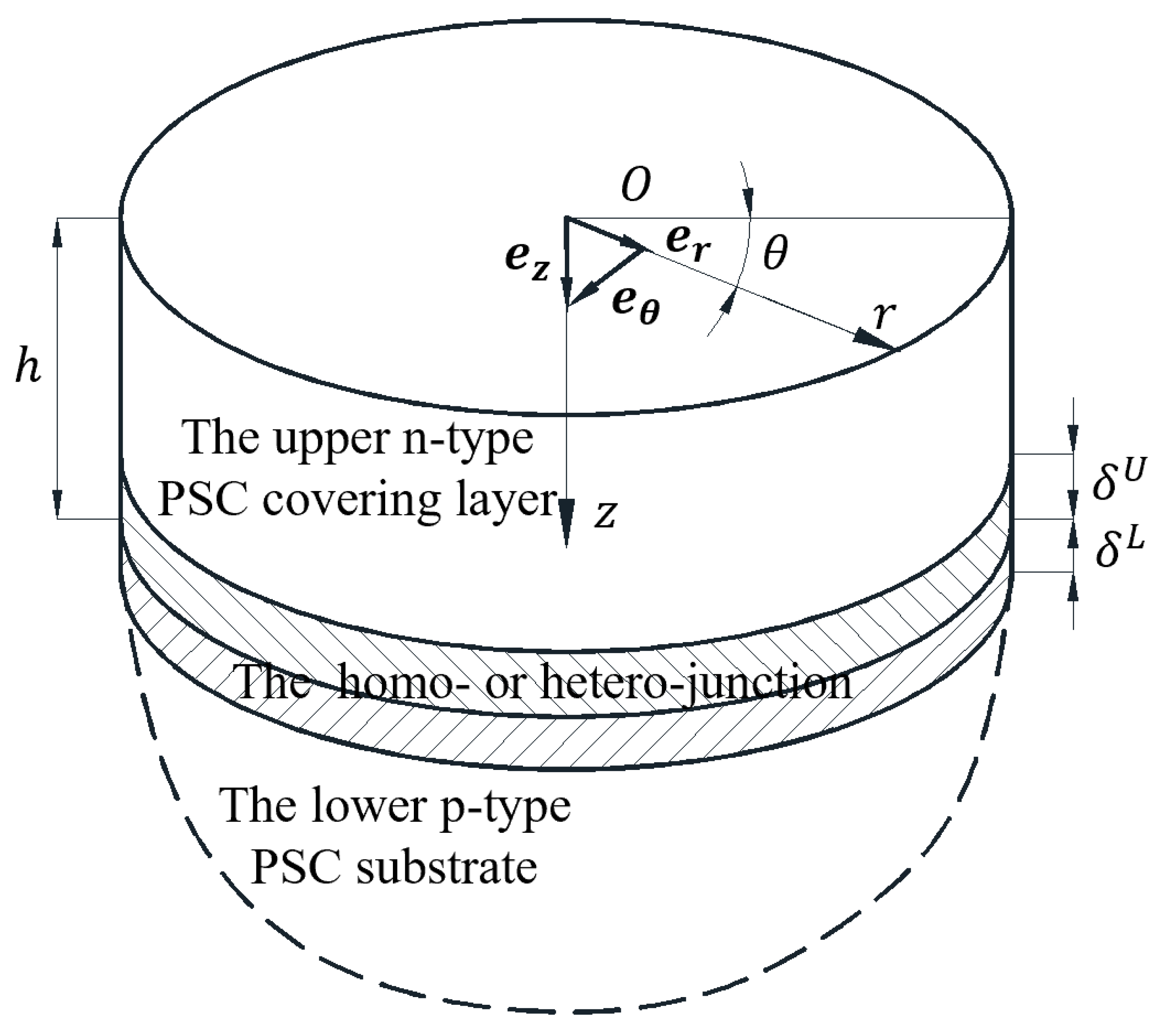
Figure 1. Schematic of a PSC semi−infinite medium.
Mathematics 12 00145 g001
Figure 2. Schematic of the functional gradient thin layer divided into a finite number of thin layers.
Mathematics 12 00145 g002
Figure 3. Distribution of steady charge carrier concentrations (a,b) and geometrical thicknesses (ce) of the homo−junction with varying doping concentrations in the upper n−type ZnO/lower p−type ZnO semi−infinite medium.
Mathematics 12 00145 g003
Figure 4. The dispersion curves (a) and attenuation curves (b) of radially propagated cylindrical SAW in the upper n−type ZnO/lower p−type ZnO semi−infinite medium with variation of the r coordinate.
Mathematics 12 00145 g004
Figure 5. Dispersion curves (a,c) and attenuation curves (b,d) of radially propagated cylindrical SAW in the upper n−type ZnO/lower p−type ZnO semi−infinite medium with varying doping concentrations.
Mathematics 12 00145 g005
Figure 6. Relative changes in the radial wave speed (a,c) and the dimensionless attenuation coefficient (b,d) of radially propagated cylindrical SAW in the upper n−type ZnO/lower p−type ZnO semi−infinite medium with varying doping concentrations.
Mathematics 12 00145 g006
Figure 7. Numerical comparations of the dispersion curves (a,c) and attenuation curves (b,d) of radially propagated cylindrical SAW in the upper n−type ZnO/lower p−type ZnO semi−infinite medium calculated by the two equivalent mathematical models.
Mathematics 12 00145 g007
Figure 8. Distribution of steady charge carrier concentrations (a,b) and geometrical thicknesses (ce) of the hetero−junction with varying doping concentrations in the upper n−type GaN/lower p−type ZnO semi−infinite medium.
Mathematics 12 00145 g008
Figure 9. Dispersion curves (a) and attenuation curves (b) of radially propagated cylindrical SAW in the upper n−type GaN/lower p−type semi−infinite medium with varying doping concentrations.
Mathematics 12 00145 g009
Figure 10. Relative changes of the radial wave speed (a) and the dimensionless attenuation coefficient (b) of radially propagated cylindrical SAW in the upper n−type GaN/lower p−type ZnO semi−infinite medium with varying doping concentrations.
Mathematics 12 00145 g010
Figure 11. Numerical comparison of the dispersion curves (a) and attenuation curves (b) of radially propagated cylindrical SAW in the upper n−type GaN/lower p−type ZnO semi−infinite medium calculated by the two equivalent mathematical models.
Mathematics 12 00145 g011
Table 1. Physical constants of ZnO and GaN.
c 11 c 13 c 33 c 44 ρ e 15 e 31 e 33 ε 11 / ε z z 0
ZnO 209.7 105.4 211.2 42.4 5665 0.48 0.567 1.32 7.57
GaN 298.4 142.5 289.2 23.1 6095 0.31 0.52 0.61 9.5
ε 33 / ε z z 0 μ 11 p μ 33 p d 11 p d 33 p μ 11 n μ 33 n d 11 n d 33 n n i
ZnO 9.03 0.008 0.008 0.0208 0.0208 100 100 260 260 1.02 × 10 16
GaN 10.3 6.53 9.82 16.99 25.53 3.4 × 10 4
c i j : G P a , ρ : K g m 3 , e i j : C m 2 ,   ε z z 0 = 8.854 × 10 12 C V 1 m 1 μ i j : 10 2 m 2 V 1 s 1 , d i j : 10 4 m 2 s 1 , n i : m 3 .
Disclaimer/Publisher’s Note: The statements, opinions and data contained in all publications are solely those of the individual author(s) and contributor(s) and not of MDPI and/or the editor(s). MDPI and/or the editor(s) disclaim responsibility for any injury to people or property resulting from any ideas, methods, instructions or products referred to in the content.