
An Innovative Power Management Strategy for Hybrid Battery–Supercapacitor Systems in Electric Vehicle


Abstract
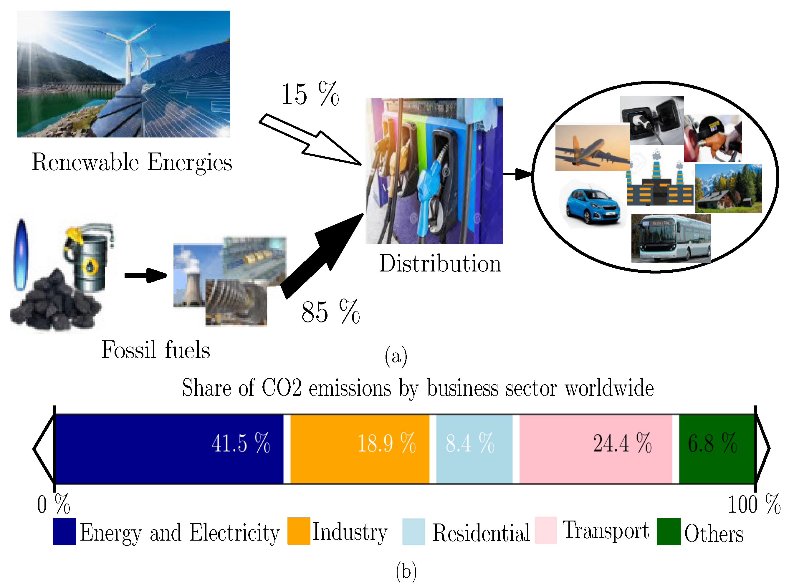
:1. Introduction
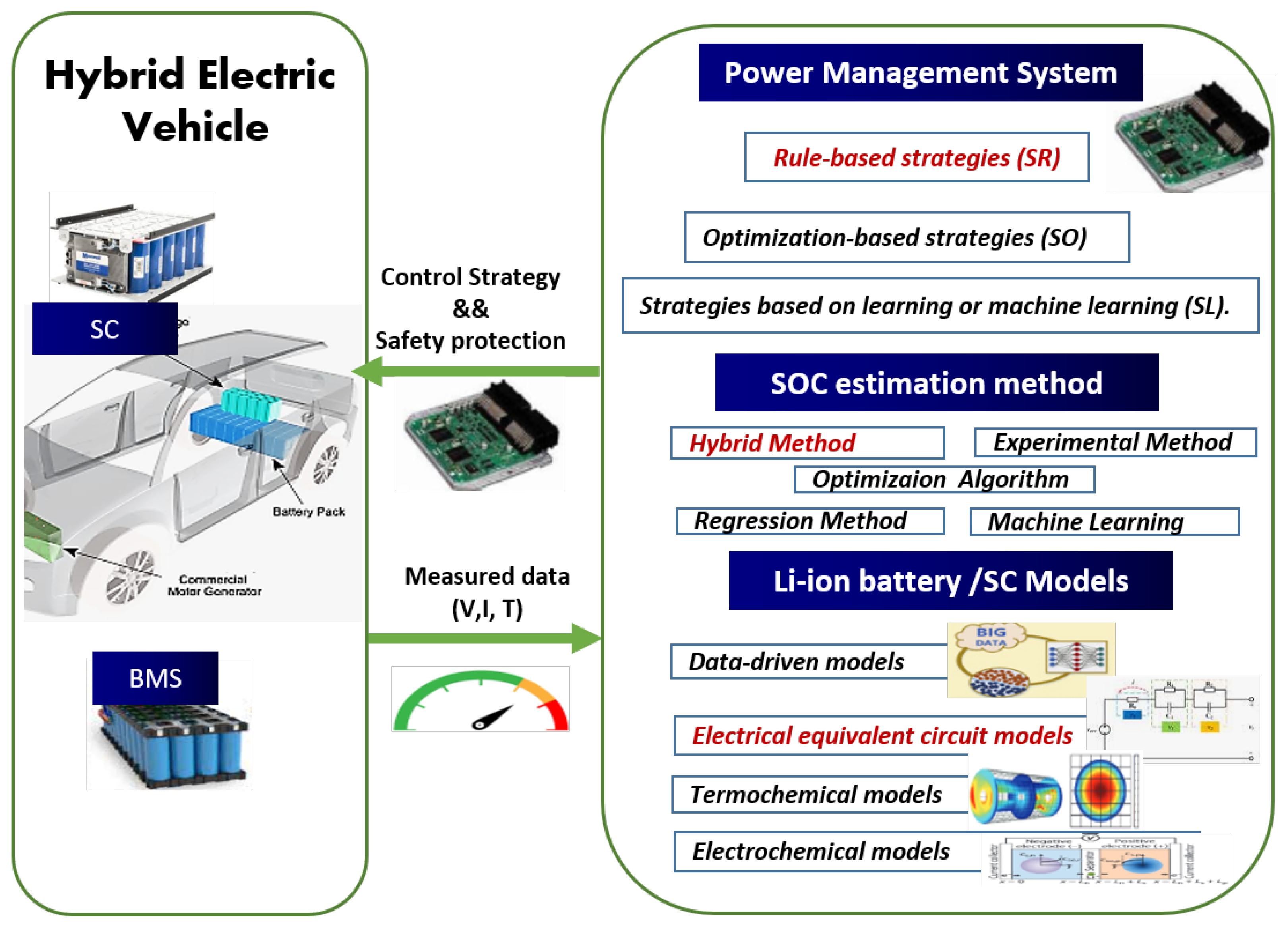
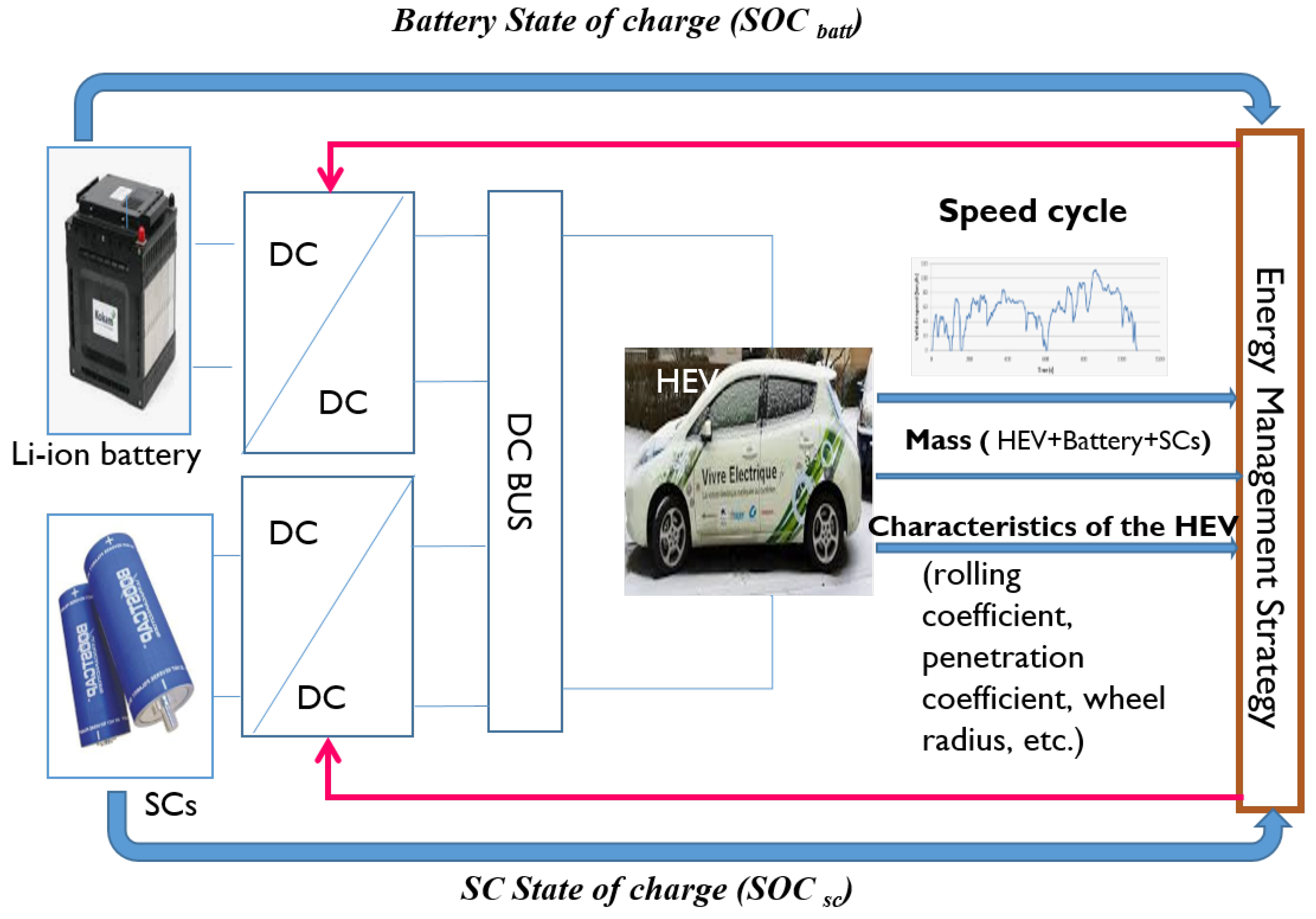
2. Electric Vehicle with Battery/SC Energy Storage
2.1. Hybrid Electric Vehicle Dynamics Model
- Aerodynamic force is given by Equation (3), which is proportional to the square of the vehicle’s speed.where A is the frontal area (m2), is the density of air (kg/m2), and is the coefficient of air penetration.
- The rolling resistance force is the resistance force generated by the tire/road contact:where is the total mass of the vehicle (engine, storage elements, and body), and the rolling resistance coefficient is expressed by Equation (5):
- Resistance due to gravity is written in the following form:
2.2. Drive Cycle
2.3. Sizing Hybrid Source
3. Modeling and State of Charge Estimation
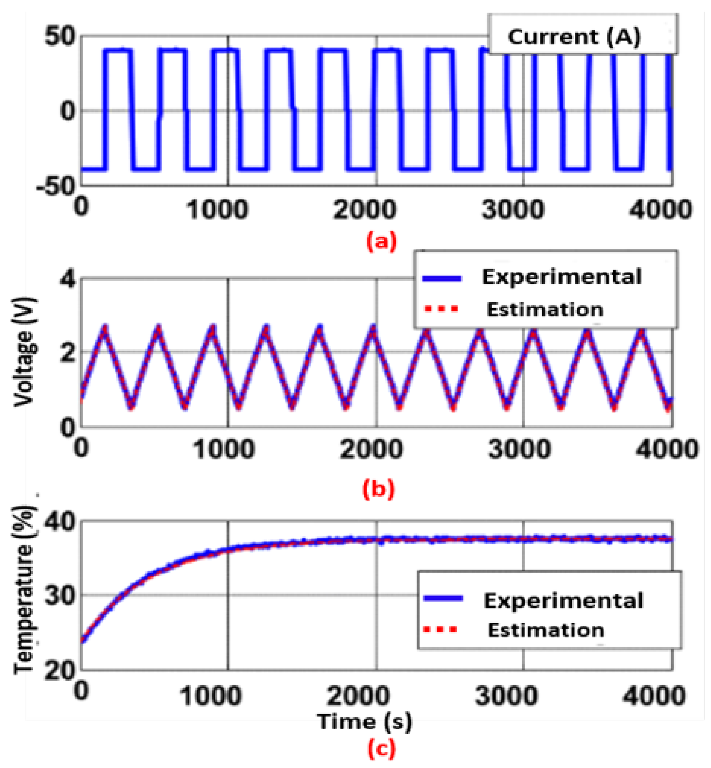
3.1. Battery ECM Model and Online SOC Estimation
- Open-circuit voltage, , which is the potential between the electrodes when the battery is completely disconnected (state of rest or relaxation).
- The internal resistance or the series resistance, , which presents the immediate ohmic voltage drop due to the resistance of electrolyte, pins, and active material.
- The first parallel branch, -, takes into account transient voltages such as double-layer effects and transition effects between ionic and electrical conductance. These transient phenomena have a time constant 1 of the order of a few seconds, which is equal to the product of and .
- The second parallel circuit element - considers long-term transient effects as the relaxation effect. The expression = . presents the time constant for these effects, which are on the order of several minutes.
3.2. Supercapacitor ECM Model
4. Active Methods of Energy Management for Hybrid Storage Sources
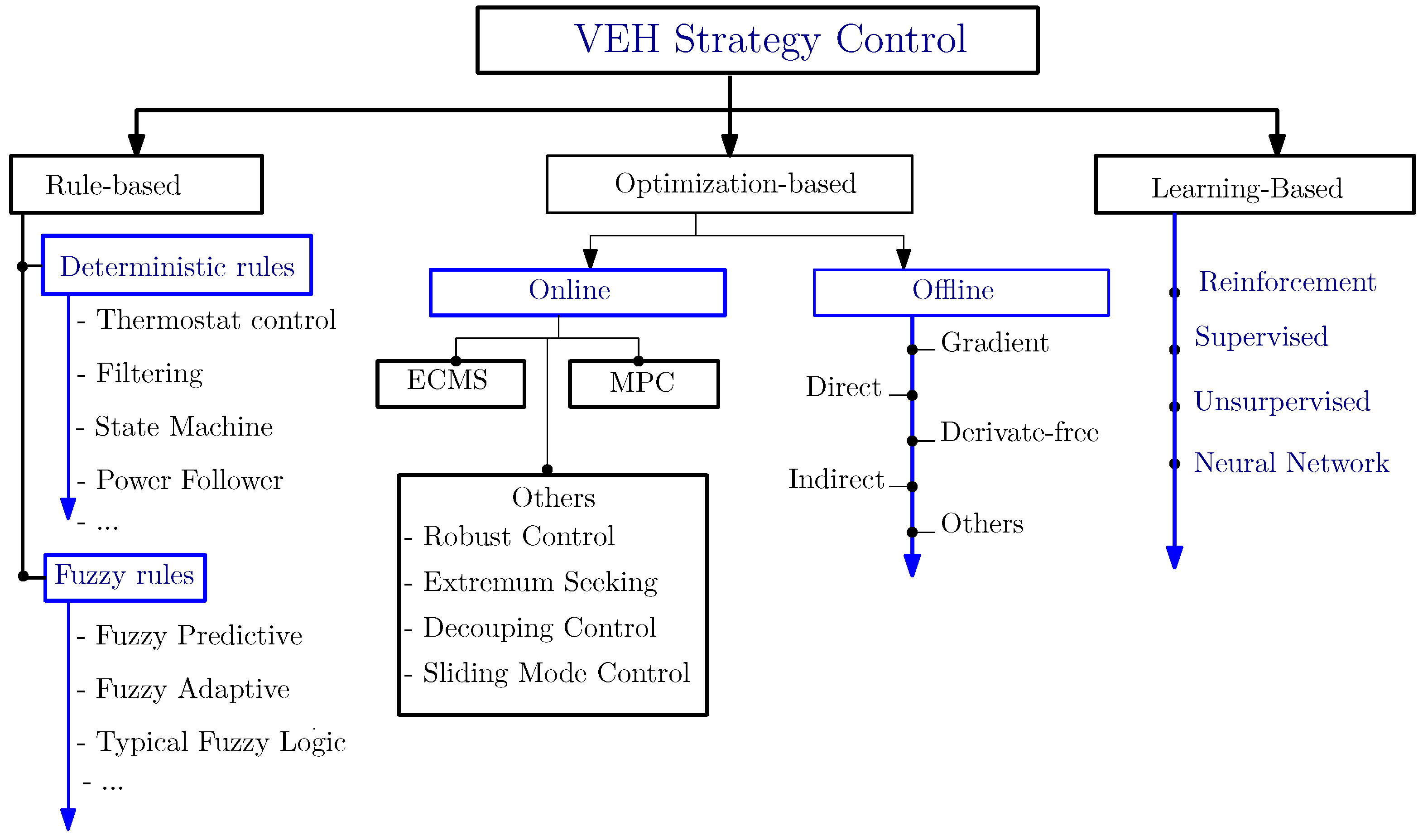
4.1. State-of-the-Art of Energy Management Strategies
- Rule-based strategies (SR);
- Optimization-based strategies (SO);
- Strategies based on learning or machine learning (SL).
- -
- Rule-based strategies (SR) utilize the expertise of engineers, translating it into executable rules that govern the powertrain’s control signals. These strategies are designed to meet specific performance criteria and consider the operational constraints of vehicle components, including the state of charge of energy storage systems (ESSs). SRs are known for their simplicity and effectiveness in real-time supervisory control but may lack adaptability under varying load conditions. This necessitates fine-tuning of vehicle parameters to align with specific performance targets.
- -
- Optimization-based strategies (SO) leverage mathematical models to determine the optimal operational sequence for a system, with the goal of minimizing a specific cost function. This approach is often used to reduce power losses within the hybrid storage system, which can be mathematically expressed as:
- ECMS (Equivalent Consumption Minimization Strategy): In the context of purely electric vehicles, ECMS is adapted to optimize the energy distribution between the battery and the supercapacitor, aiming to enhance overall energy efficiency and prolong the operational lifespan of the energy storage components.
- MPC (Model Predictive Control): MPC’s role in purely electric vehicles involves predicting future energy requirements and optimizing control actions for efficient energy use. It considers various factors, such as driving conditions and vehicle load, ensuring optimal performance of the electric powertrain.
- -
- Machine-learning-based strategies (SL) represent a paradigm shift in power management system (PMS) design for electric vehicles (EVs), bringing data-driven adaptability to energy management. Strategies under the SL umbrella, such as neural networks (NNs), support vector machines (SVMs), and reinforcement learning (RL), learn from historical and live driving data. This learning capability enables the PMS to proactively adjust to changing vehicle demands and driver behaviors.
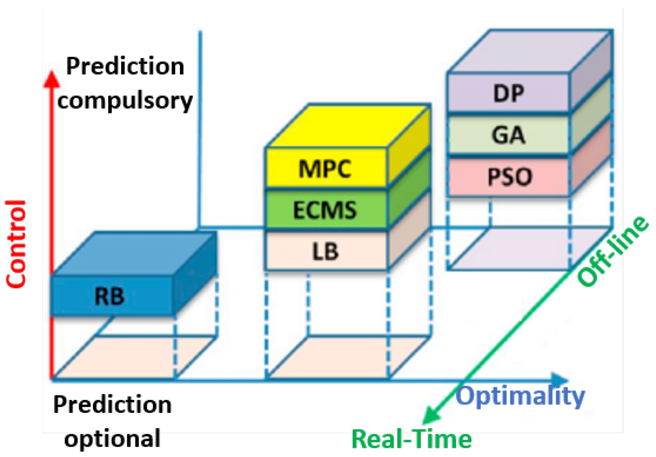
- MPC: model predictive control;
- ECMS: equivalent consumption minimization strategy;
- LB: look-ahead control;
- RB: rule-based control;
- DP: dynamic programming;
- GA: genetic algorithm;
- PSO: particle swarm optimization.
4.2. Continuous Regulation with Dynamic Battery Power Limiting
- **Limiting Method (ML[/]): **The ML strategy effectively moderates the power or current of the Li-ion battery within a defined range, specified by and . It ensures that any demand exceeding these limits is accommodated by the supercapacitor (), striking a balance between battery protection and load requirements.
- **Filter Method (MF[]): **Operating on an open-loop control scheme, the MF method distributes the power demand across the battery and using a low-pass filter. High-frequency power requirements are assigned to the , while the Li-ion battery manages steady, low-frequency demands. This approach effectively mitigates battery stress and enhances response efficiency.
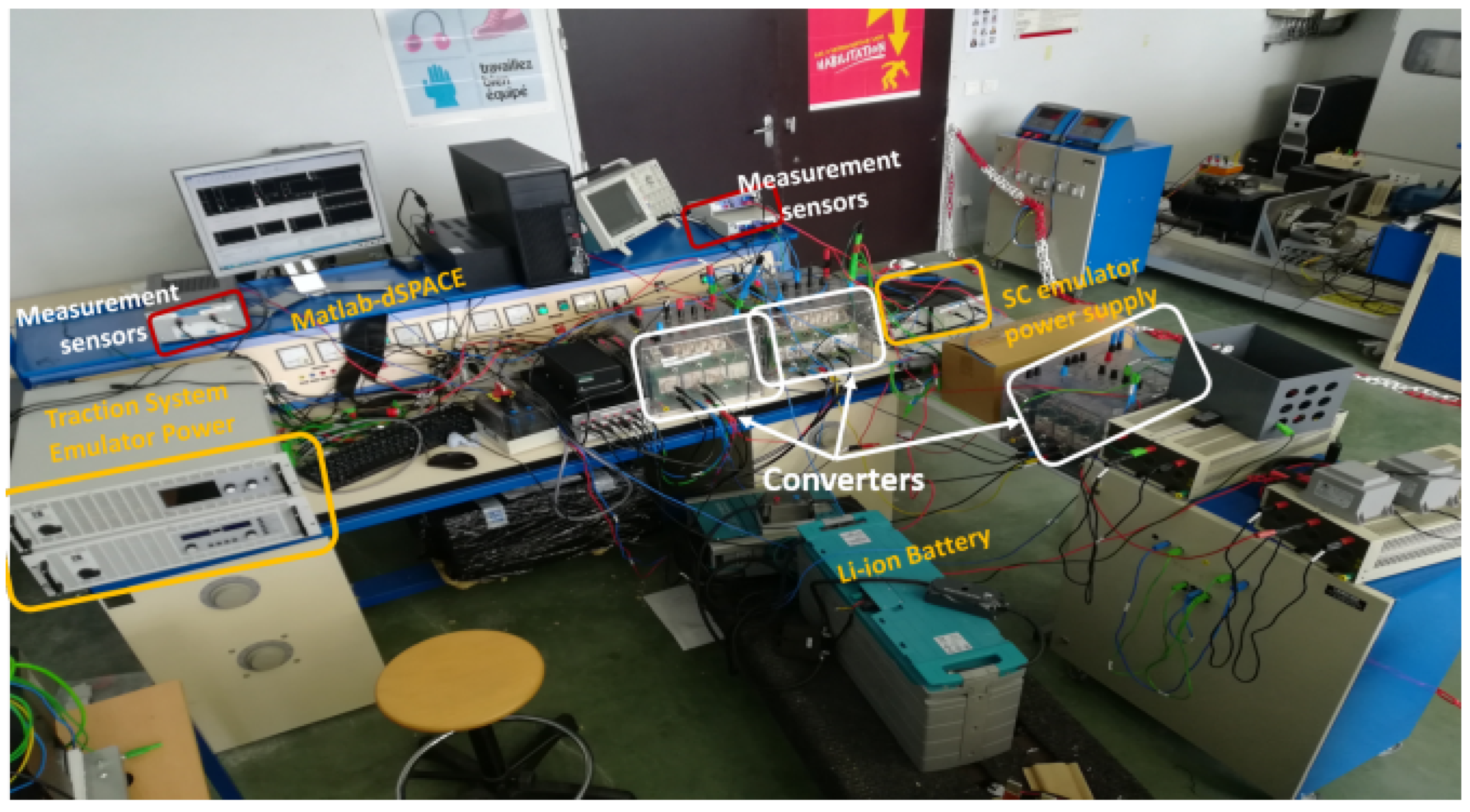
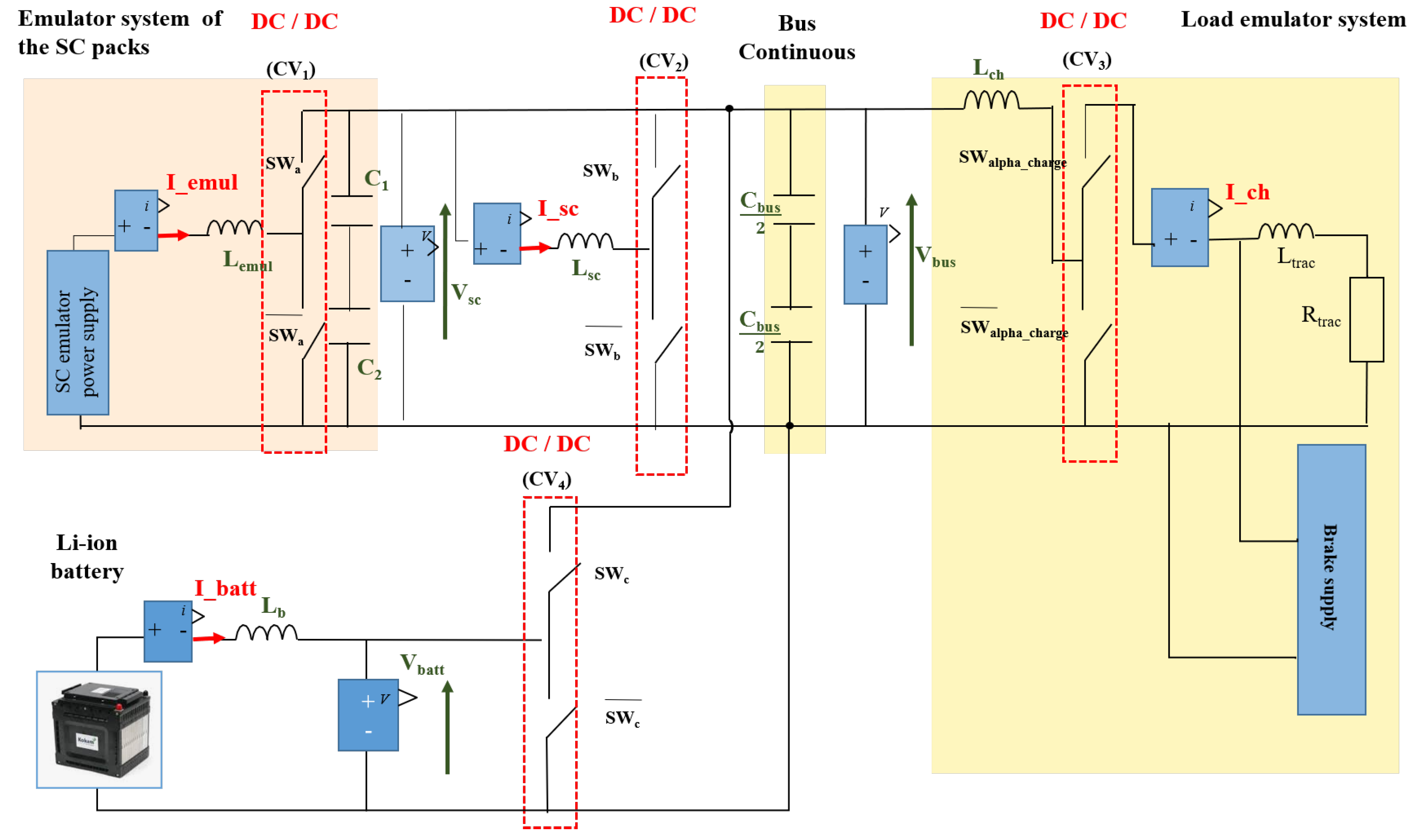
5. Validation of Energy Management Strategies
- Check system security during EV operation.
- Ensure EV braking load and traction satisfaction.
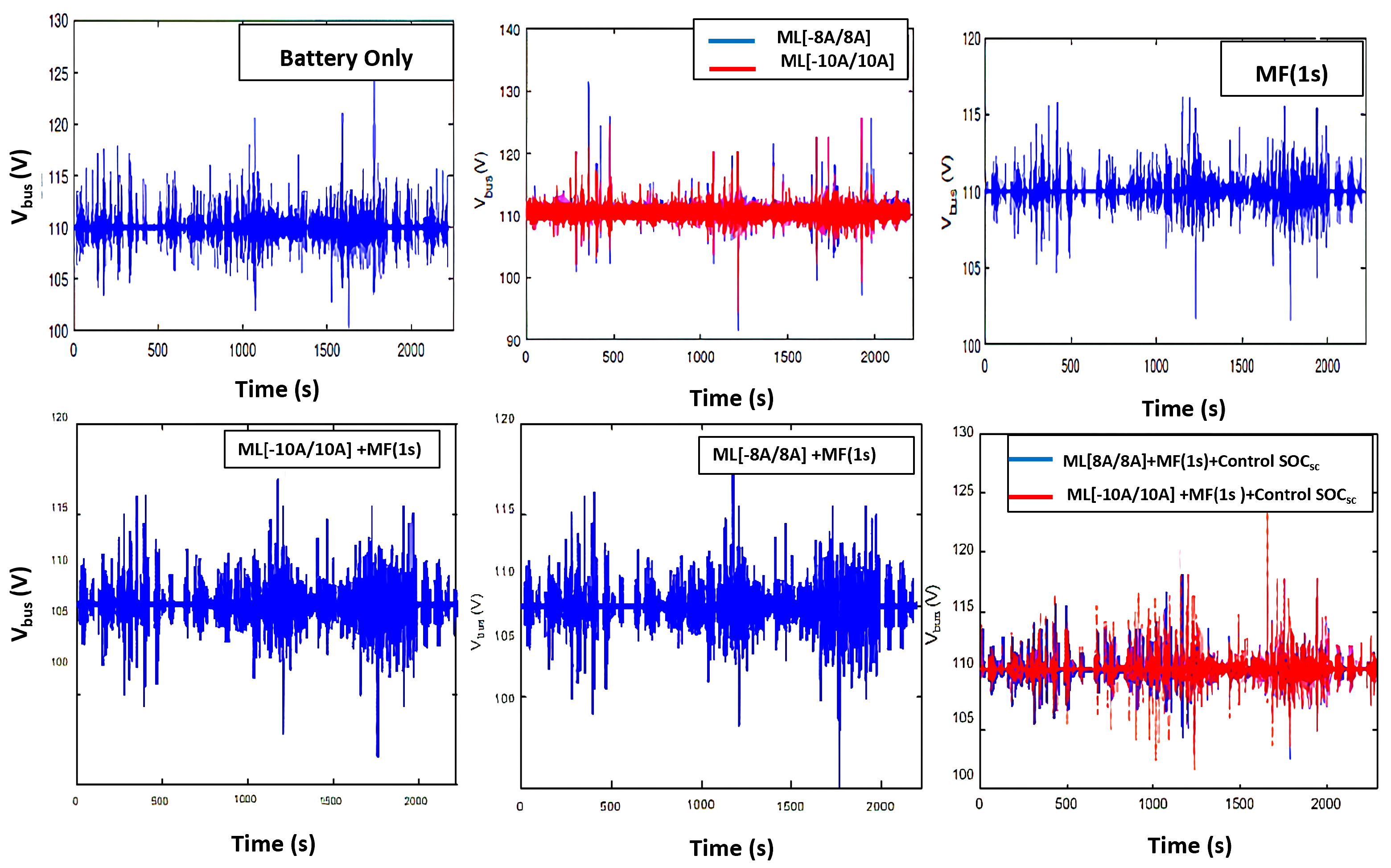
- Maintain DC bus stability around 110 V reference.
- Reduce stress on the battery: The number of charge and discharge cycles a battery may go through before losing its performance is known as cycle life. Besides, the depth of discharge has a considerable impact on the cycle life of Li-ion batteries, as it presents the capacity amount of a battery’s storage that is actually being used.
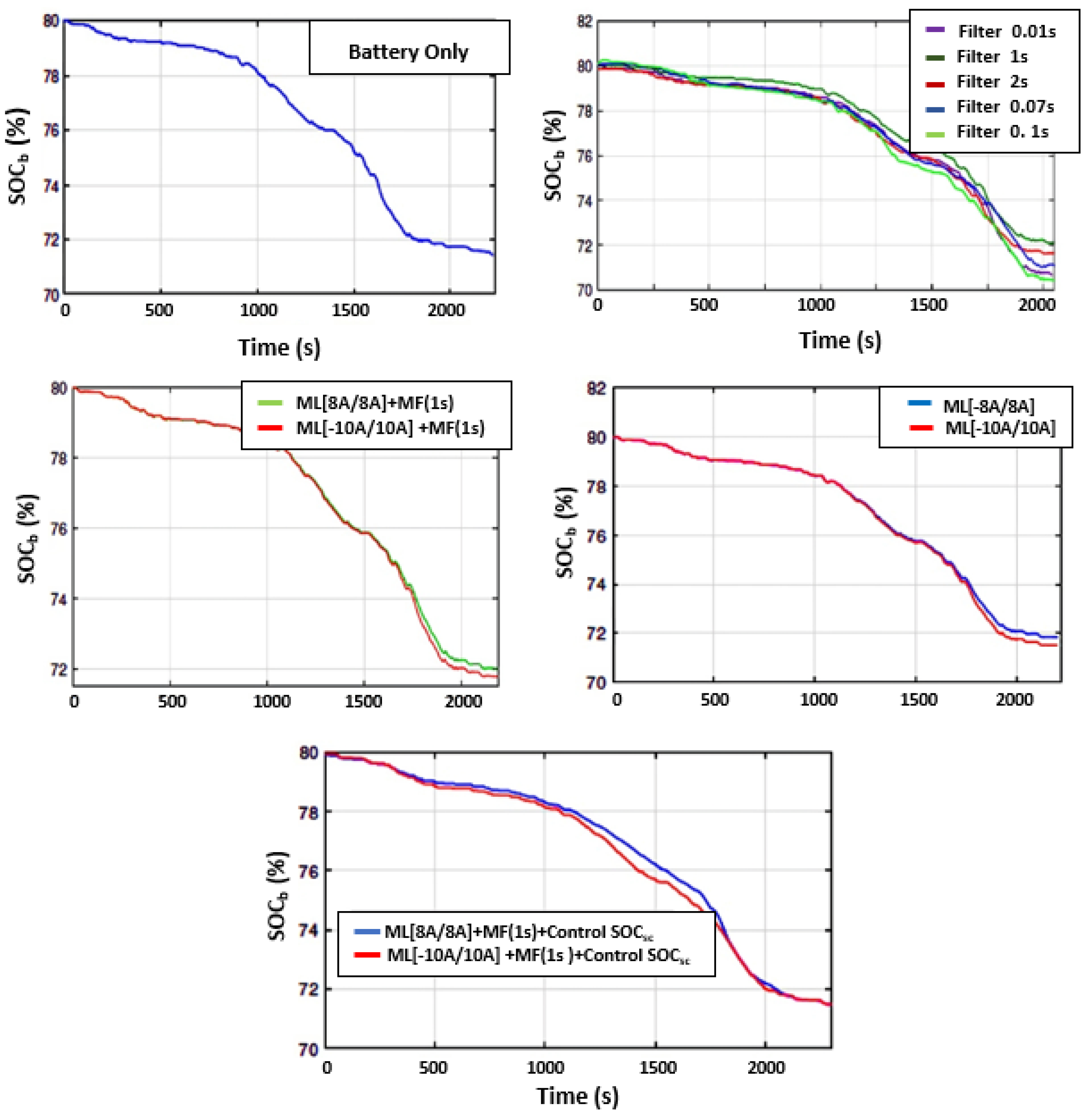
- We implemented the MF strategy with five different values of (0.01 s, 0.07 s, 0.1 s, 1 s, and 2 s) to assess the impact of the time constant on power sharing between the Li-ion battery and SC. remains constant throughout the ARTEMIS driving cycle. After experimental implementation, Figure 17 depicts the evolution of the battery’s state over time. A comparison of practical results indicates that Figure 17 corresponds to 1 s, leading to a significant reduction in current demands on the battery compared to other time constants, with the lowest battery state of charge.
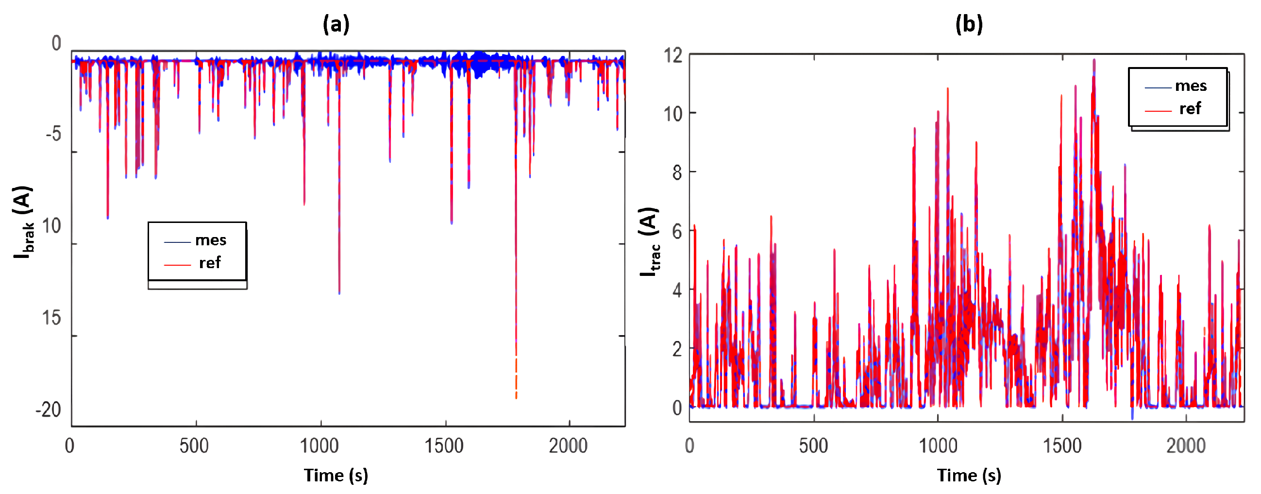
- The load current, resulting from traction and braking currents, is displayed in Figure 12a,b, respectively. Both figures unmistakably demonstrate that the measured currents closely follow the reference signals due to proper regulation functioning.
- Experimental testing in Figure 15 illustrates the regulators’ efficiency in adapting to load changes and maintaining the required bus voltage of 110.
- Calculation of SC and Li-ion battery effective currents, along with reduction rates for various scenarios, is summarized in Table 3. Note the maximum constraints applied to the battery in the case of a single source (no hybridization), with an effective current of 4.089 A. In EV operation with a single source, the battery experiences charge/discharge peaks, while these peaks decrease by varying percentages for the six management scenarios (EV to hybrid source). Single-source EV operation is more “aggressive” on Li-ion cell packs, leading to a rapid decline in battery life.
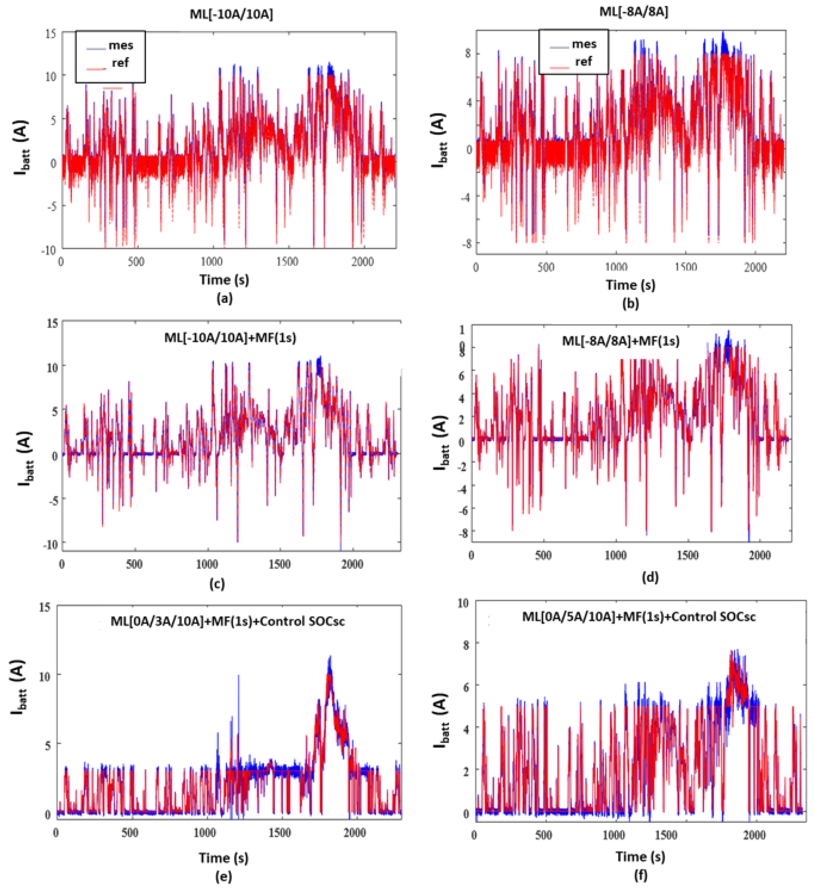
- Battery currents shown in Figure 13 reveal that the main source current remains within the limit band imposed by the PMS. The battery’s state of charge decreases with current limit reduction, while the effective SC current increases with this band limit reduction, especially in strategies ML[−10A/10A], ML[−8A/8A], ML[−10A/10A] + MF(1s), and ML[−8A/8A] + MF(1s) (see Figure 16 and Figure 17).
- The enhanced approach ML[0/Sup1/Sup2] yields significantly improved battery current with minimal fluctuations. The battery’s effective current is lower than Sup1 at 3 A when Sup1 is limited to 5 A (see Table 3).
- Results in Figure 18 exhibit a 27.44% gain (in Ah) in energy exchanged by the battery for the regulation method with three battery power variable limits, contributing to longer battery life. Thus, the proposed method demonstrates the supercapacitor’s significant role in minimizing battery stress.
- The variable regulation method ensures minimal battery stresses (Table 3), with a 30.18% reduction in stresses compared to the single-phase case. This method also requires the supercapacitor’s state of charge to return to the reference value.
6. Conclusions
Author Contributions
Funding
Data Availability Statement
Conflicts of Interest
References
- Zhang, R.; Johnson, N.M.; Li, Y. Establishing the exposure–outcome relation between airborne particulate matter and children’s health. Thorax 2022, 77, 322–323. [Google Scholar] [CrossRef] [PubMed]
- Standage, T. The Lost History of the Electric Car—And What It Tells Us about the Future of Transport. Available online: https://www.theguardian.com/technology/2021/aug/03/lost-history-electric-car-future-transport (accessed on 1 January 2023).
- Henderson, J. EVs are not the answer: A mobility justice critique of electric vehicle transitions. Ann. Am. Assoc. Geogr. 2020, 110, 1993–2010. [Google Scholar] [CrossRef]
- Vellingiri, M.T.; Mehedi, I.M.; Palaniswamy, T. A novel deep learning-based state-of-charge estimation for renewable energy management system in hybrid electric vehicles. Mathematics 2022, 10, 260. [Google Scholar] [CrossRef]
- Jasim, A.M.; Jasim, B.H.; Baiceanu, F.C.; Neagu, B.C. Optimized sizing of energy management system for off-grid hybrid solar/wind/battery/biogasifier/diesel microgrid system. Mathematics 2023, 11, 1248. [Google Scholar] [CrossRef]
- Mohammed, S.A.Q.; Jung, J.W. A comprehensive state-of-the-art review of wired/wireless charging technologies for battery electric vehicles: Classification/common topologies/future research issues. IEEE Access 2021, 9, 19572–19585. [Google Scholar] [CrossRef]
- Yankevich, N.; Yankevich, S. Electromobility Market: Perspectives and Risks. Glob. Econ. Sci. 2022, 162–186. [Google Scholar] [CrossRef]
- Song, F.; Mehedi, H.; Liang, C.; Meng, J.; Chen, Z.; Shi, F. Review of transition paths for coal-fired power plants. Glob. Energy Interconnect. 2021, 4, 354–370. [Google Scholar] [CrossRef]
- Zhang, J.; Lu, J.; Pan, J.; Tan, Y.; Cheng, X.; Li, Y. Implications of the development and evolution of global wind power industry for China—An empirical analysis is based on public policy. Energy Rep. 2022, 8, 205–219. [Google Scholar] [CrossRef]
- kizi Toshmanova, M.S. Analysis of the Activities of the Largest Transnational Banks in the World and Their Role in the Global Financial System. Eurasian J. Law, Financ. Appl. Sci. 2022, 2, 142–146. [Google Scholar]
- IEA. Global ev Outlook 2022: Securing Supplies for an Electric Future; Elsevier: Amsterdam, The Netherlands, 2022. [Google Scholar]
- Liu, R.; Wang, C.; Tang, A.; Zhang, Y.; Yu, Q. A twin delayed deep deterministic policy gradient-based energy management strategy for a battery-ultracapacitor electric vehicle considering driving condition recognition with learning vector quantization neural network. J. Energy Storage 2023, 71, 108147. [Google Scholar] [CrossRef]
- Bhat, M.Y.; Hashmi, S.; Khan, M.; Choi, D.; Qurashi, A. Frontiers and recent developments on supercapacitor’s materials, design, and applications: Transport and power system applications. J. Energy Storage 2023, 58, 106104. [Google Scholar] [CrossRef]
- Prathibha, P.; Samuel, E.R. Performance Analysis of Electric Car Based on Drag Coefficients and Road Angles. In Proceedings of the 2022 2nd International Conference on Power Electronics & IoT Applications in Renewable Energy and its Control (PARC), Mathura, India, 21–22 January 2022; pp. 1–6. [Google Scholar]
- Gillespie, T. Fundamentals of Vehicle Dynamics; SAE International: Warrendale, PA, USA, 2021. [Google Scholar]
- Hamida, M.A.; El-Sehiemy, R.A.; Ginidi, A.R.; Elattar, E.; Shaheen, A.M. Parameter identification and state of charge estimation of Li-Ion batteries used in electric vehicles using artificial hummingbird optimizer. J. Energy Storage 2022, 51, 104535. [Google Scholar] [CrossRef]
- Mesbahi, T.; Sugrañes, R.B.; Bakri, R.; Bartholomeüs, P. Coupled electro-thermal modeling of lithium-ion batteries for electric vehicle application. J. Energy Storage 2021, 35, 102260. [Google Scholar] [CrossRef]
- Otkur, M.; Doust, M. Kuwait Driving Cycle Generation Using Micro-Trip Combination Optimization Method Based on WLTC. Int. J. Automot. Eng. 2023, 14, 51–57. [Google Scholar] [CrossRef] [PubMed]
- Rizoug, N.; Mesbahi, T.; Sadoun, R.; Bartholomeus, P.; Le Moigne, P. Development of new improved energy management strategies for electric vehicle battery/supercapacitor hybrid energy storage system. Energy Effic. 2018, 11, 823–843. [Google Scholar] [CrossRef]
- Mesbahi, T.; Rizoug, N.; Bartholomeus, P.; Sadoun, R.; Khenfri, F.; Le Moigne, P. Optimal energy management for a li-ion battery/supercapacitor hybrid energy storage system based on a particle swarm optimization incorporating Nelder–Mead simplex approach. IEEE Trans. Intell. Veh. 2017, 2, 99–110. [Google Scholar] [CrossRef]
- Degaa, L.; Rizoug, N.; Bendjedia, B.; Saidane, A.; Larouci, C. Sizing improvement of hybrid storage system composed with high energy and high power Li-ion batteries for automotive applications. Proc. Inst. Mech. Eng. Part I J. Syst. Control. Eng. 2019, 233, 870–876. [Google Scholar] [CrossRef]
- Liu, W.; Placke, T.; Chau, K. Overview of batteries and battery management for electric vehicles. Energy Rep. 2022, 8, 4058–4084. [Google Scholar] [CrossRef]
- Li, S.; Zhang, C.; Du, J.; Cong, X.; Zhang, L.; Jiang, Y.; Wang, L. Fault diagnosis for lithium-ion batteries in electric vehicles based on signal decomposition and two-dimensional feature clustering. Green Energy Intell. Transp. 2022, 1, 100009. [Google Scholar] [CrossRef]
- Li, Z.; Shi, X.; Shi, M.; Wang, X.; Wang, Y.; Sun, H. Online Estimation of Battery Equivalent Circuit Model Parameters Using Decoupled Least Squares Technique. In Proceedings of the 2020 IEEE/IAS Industrial and Commercial Power System Asia (I&CPS Asia), Weihai, China, 13–15 July 2020; pp. 1357–1362. [Google Scholar]
- Zhang, C.; Allafi, W.; Dinh, Q.; Ascencio, P.; Marco, J. Online estimation of battery equivalent circuit model parameters and state of charge using decoupled least squares technique. Energy 2018, 142, 678–688. [Google Scholar] [CrossRef]
- Hossain, M.; Saha, S.; Haque, M.E.; Arif, M.T.; Oo, A.M.T. A parameter extraction method for the Thevenin equivalent circuit model of Li-ion batteries. In Proceedings of the 2019 IEEE Industry Applications Society Annual Meeting, Baltimore, MD, USA, 29 September–3 October 2019; pp. 1–7. [Google Scholar]
- Jarraya, I.; Masmoudi, F.; Chabchoub, M.H.; Trabelsi, H. An online state of charge estimation for Lithium-ion and supercapacitor in hybrid electric drive vehicle. J. Energy Storage 2019, 26, 100946. [Google Scholar] [CrossRef]
- Jarrraya, I.; Degaa, L.; Rizoug, N.; Chabchoub, M.H.; Trabelsi, H. Comparison study between hybrid Nelder-Mead particle swarm optimization and open circuit voltage—Recursive least square for the battery parameters estimation. J. Energy Storage 2022, 50, 104424. [Google Scholar] [CrossRef]
- Rizoug, N.; Bartholomeus, P.; Le Moigne, P. Modeling and characterizing supercapacitors using an online method. IEEE Trans. Ind. Electron. 2010, 57, 3980–3990. [Google Scholar] [CrossRef]
- Mesbahi, T.; Bartholomeüs, P.; Rizoug, N.; Sadoun, R.; Khenfri, F.; Le Moigne, P. Advanced model of hybrid energy storage system integrating lithium-ion battery and supercapacitor for electric vehicle applications. IEEE Trans. Ind. Electron. 2020, 68, 3962–3972. [Google Scholar] [CrossRef]
- Durganjali, C.S.; Chawla, V.; Raghavan, H.; Radhika, S. Design, development, and techno-economic analysis of extreme fast charging topologies using Super Capacitor and Li-Ion Battery combinations. J. Energy Storage 2022, 56, 106140. [Google Scholar] [CrossRef]
- Masaki, M.S.; Zhang, L.; Xia, X. Fuzzy logic control of plug-in supercapacitor storage for thermoelectric management of batteries. Renew. Energy Focus 2022, 43, 59–73. [Google Scholar] [CrossRef]
- Xiong, R.; Duan, Y.; Cao, J.; Yu, Q. Battery and ultracapacitor in-the-loop approach to validate a real-time power management method for an all-climate electric vehicle. Appl. Energy 2018, 217, 153–165. [Google Scholar] [CrossRef]
- Ouddah, N.; Adouane, L. Hybrid Energy Management Strategy Based on Fuzzy Logic and Optimal Control for Tri-Actuated Powertrain System. IEEE Trans. Veh. Technol. 2019, 68, 5343–5355. [Google Scholar] [CrossRef]
- Krithika, V.; Subramani, C. A comprehensive review on choice of hybrid vehicles and power converters, control strategies for hybrid electric vehicles. Int. J. Energy Res. 2018, 42, 1789–1812. [Google Scholar] [CrossRef]
- Baronti, F.; Vazquez, S.; Chow, M.Y. Modeling, control, and integration of energy storage systems in e-transportation and smart grid. IEEE Trans. Ind. Electron. 2018, 65, 6548–6551. [Google Scholar]
- Tran, D.D.; Vafaeipour, M.; El Baghdadi, M.; Barrero, R.; Van Mierlo, J.; Hegazy, O. Thorough state-of-the-art analysis of electric and hybrid vehicle powertrains: Topologies and integrated energy management strategies. Renew. Sustain. Energy Rev. 2019, 119, 109596. [Google Scholar] [CrossRef]
- Rimpas, D.; Kaminaris, S.D.; Piromalis, D.D.; Vokas, G. Real-Time Management for an EV Hybrid Storage System Based on Fuzzy Control. Mathematics 2023, 11, 4429. [Google Scholar] [CrossRef]
- Ali, A.M.; Söffker, D. Towards optimal power management of hybrid electric vehicles in real-time: A review on methods, challenges, and state-of-the-art solutions. Energies 2018, 11, 476. [Google Scholar] [CrossRef]
- Vidhya, S.D.; Balaji, M. Modelling, design and control of a light electric vehicle with hybrid energy storage system for Indian driving cycle. Meas. Control. 2019, 52, 0020294019858212. [Google Scholar] [CrossRef]
- Pang, H.; Wu, L.; Liu, J.; Liu, X.; Liu, K. Physics-informed neural network approach for heat generation rate estimation of lithium-ion battery under various driving conditions. J. Energy Chem. 2023, 78, 1–12. [Google Scholar] [CrossRef]
- Paul, T.; Mesbahi, T.; Durand, S.; Flieller, D.; Uhring, W. Sizing of lithium-ion battery/supercapacitor hybrid energy storage system for forklift vehicle. Energies 2020, 13, 4518. [Google Scholar] [CrossRef]
- Demircali, A.; Koroglu, S. Modular energy management system with Jaya algorithm for hybrid energy storage in electric vehicles. Int. J. Energy Res. 2022, 46, 21497–21510. [Google Scholar] [CrossRef]
- Shen, Y.; Xie, J.; He, T.; Yao, L.; Xiao, Y. CEEMD-fuzzy Control Energy Management of Hybrid Energy Storage Systems in Electric Vehicles. IEEE Trans. Energy Convers. 2023. [Google Scholar] [CrossRef]


| Characteristics | Symbol | Value |
|---|---|---|
| Mass | M | 1020 kg |
| Surface | S | 2.75 m2 |
| Maximum speed | V | 170 km/h |
| Air penetration coefficient | 0.3 | |
| Rolling resistance coefficient | 0.008 | |
| Curve rolling resistance coefficient | ||
| Air density | 1.28 kg/m3 |
| PARAMETERS | VALUE |
|---|---|
| Li-ion battery | Cell Capacity = 15 Ah |
| Number of cells in series | 26 cells |
| Number of cells in parallel | 1 branche |
| Voltage | 95 V |
| Current (min./max.) | (15/30) A |
| Supercapacitor | |
| Number of cells in series | 34 |
| Capacity | 1000 F |
| Voltage | 92 V |
| Current (min./max.) | (−40/40) A |
| DC CONVERTER | |
| MAXIMAL POWER | 6.5 kW |
| Voltage | 200 V |
| Current (max.) | 32 A |
| BRAKING LOAD (max.) | 32 A |
| TRACTION LOAD (max.) | 32 A |
| PMS Method | Percentage of Stress Minimized | ||
|---|---|---|---|
| (A) | (A) | Compared to a Single Source | |
| Li-ion battery only | 0 | 4.089 | 100% |
| MF(1s) | 1.196 | 3.747 | 91.63% |
| ML[−10A/10A] | 0.690 | 3.661 | 89.53% |
| ML[−10A/10A] + MF(1s) | 1.405 | 3.553 | 86.89% |
| ML[0A/5A/10A] + MF(1s) + Control | 1.957 | 2.893 | 70.75% |
| ML[0A/3A/10A] + MF(1s) + Control | 1.432 | 2.854 | 69.80% |
Disclaimer/Publisher’s Note: The statements, opinions and data contained in all publications are solely those of the individual author(s) and contributor(s) and not of MDPI and/or the editor(s). MDPI and/or the editor(s) disclaim responsibility for any injury to people or property resulting from any ideas, methods, instructions or products referred to in the content. |
© 2023 by the authors. Licensee MDPI, Basel, Switzerland. This article is an open access article distributed under the terms and conditions of the Creative Commons Attribution (CC BY) license (https://creativecommons.org/licenses/by/4.0/).
Share and Cite
Jarraya, I.; Abdelhedi, F.; Rizoug, N. An Innovative Power Management Strategy for Hybrid Battery–Supercapacitor Systems in Electric Vehicle. Mathematics 2024, 12, 50. https://doi.org/10.3390/math12010050
Jarraya I, Abdelhedi F, Rizoug N. An Innovative Power Management Strategy for Hybrid Battery–Supercapacitor Systems in Electric Vehicle. Mathematics. 2024; 12(1):50. https://doi.org/10.3390/math12010050
Chicago/Turabian StyleJarraya, Imen, Fatma Abdelhedi, and Nassim Rizoug. 2024. "An Innovative Power Management Strategy for Hybrid Battery–Supercapacitor Systems in Electric Vehicle" Mathematics 12, no. 1: 50. https://doi.org/10.3390/math12010050