Abstract
Due to their high specific stiffness, particularly in bending, along with their strong design capabilities, stiffened plates have become a prevalent structural solution in aerospace and various other fields. In pursuit of optimizing such structures, a topology optimization method named Heaviside-function-based directional growth topology parameterization (H-DGTP) was proposed in our previous work. However, this approach is limited to designing planar, single-sided stiffened structures. Thus, this paper extends the scope of this method to encompass double-sided, curved, stiffened panels, presenting a topology optimization technique tailored for such configurations. Specifically, considering the position, shape of the curved panels, and the arrangement and height of the stiffeners as design variables, while prioritizing structural stiffness as the objective, a topology optimization model for double-sided curved stiffened plate structures is established, and the corresponding sensitivities of the objective with respect to the design variables are analytically derived. Numerical examples illustrate that simultaneously optimizing the position and shape of the plate, as well as the layout and height of the stiffeners on both sides of the curved plate, results in greater stiffness compared to optimizing only part of these variables, validating the necessity and effectiveness of the proposed method.
MSC:
74P05
1. Introduction
The stiffened plate structure, composed of a base plate and several stiffeners, is of great significance in the fields of machinery, aerospace, etc., for its high rigidity-to-weight ratio and strong design freedom. Previous studies have shown that by reasonably optimizing the plate shape and stiffener layout, the mechanical properties of the stiffened plate structure can be improved effectively [1,2,3]. Therefore, establishing a systematic optimization design method for a stiffened plate structure has become a research hotspot [4,5,6,7]. In recent years, applying genetic algorithms and other intelligent algorithms to optimize stiffened plate structures has made great progress [8]. However, the shortcomings of these methods, such as low computational efficiency, few achievable design variables, and limited optimization space, limit their application. Casting is a very commonly used manufacturing process for the stiffened structure due to its advantages, including cost-effectiveness, complex shape formation, and high material utilization [9]. Hence, casting provides a mature manufacturing technology for complex stiffened plate structures. However, the casting process also has requirements regarding the shape of the casting; for example, the shape of the casting should be protruding, and internal holes should be avoided [10]. If this is not the case, the casting may have defects, or casting failure may be experienced.
Topology optimization is currently one of the most powerful structural design methods. It can obtain innovative configurations with an excellent performance by seeking the optimal layout of materials under given objectives and constraints [11]. As an intelligent and systematic optimization design method, it can design products according to performance requirements and manufacturing capacity. Therefore, topology optimization is widely used to improve the structural properties of materials in aerospace and other fields [12,13]. Various topology optimization methods have been proposed in the past few decades, including homogenization-based methods [14], density-based methods [15], level set methods [16], evolution methods [17], and feature-mapping methods [18,19]. In the context of topology optimization, how to generate designs that can be manufactured by casting is of great importance. In this direction, several studies have been conducted. For example, a level-set-based method for the conceptual design shape and topology optimization of castings is proposed in the work of Wang et al. [20], and this method can conveniently consider casting constraints and traditional material volume constraints. Xu et al. [21] proposed a topology optimization method for natural frequency optimization considering casting constraints.
So far, several topology optimization methods for the stiffened layout of plate and shell structures have been developed [22,23,24]. Cheng and Olhoff developed a topology optimization method to design the thickness of plates to realize the optimal design of stiffened plate structures [25]. Rais-Rohani and Lokits also utilized the topology optimization method to explore the design aspects of composite stiffeners [26]. Furthermore, Krog and Olhoff [27] derived a stiffened structure by employing the homogenization method and strategically designing laminated microstructure parameters. In addition, Gersborg and Andreasen proposed a parametric interpolation format based on a three-dimensional structure to delineate stiffener height [19]. The underlying concept was to identify the interface between the solid and hollow materials along the stiffener to attain an optimal structure. Moreover, Liu et al. [28] developed a novel parametric method for the design of single-sided stiffened plate structures by using the Heaviside function, which is referred to as Heaviside-function-based directional growth topology parameterization (H-DGTP). Also, Sun et al. [29] proposed a multiple unidirectional material field-based topology optimization method for thin-walled structures with directional straight stiffeners. Huang et al. [30] developed a mesh-deformation-based integrated topology and shape optimization framework for stiffened curved shells. Sun et al. [31] proposed an isogeometric-analysis-based stiffness spreading method for stiffener layout optimization. Up to now, the above works have mainly focused on single-sided stiffened structures. However, the design space of a single-sided stiffened structure is not large enough to accommodate complex design requirements. Hence, developing a design theory and method for single-sided stiffened plates to increase the design space is an important direction.
Under above context, an improved H-DGTP-based topology optimization method for double-sided stiffened plates is proposed in this paper, where the main contribution is that the scope of the improved method is extended from single-sided stiffened plates to double-sided ones. In the proposed method, two types of design variables are introduced: one is used to describe the shape of the reference plate in relation to the height of the interpolation point of the reference plate; the other is used to describe the double-sided stiffener layout above and below the reference plate in relation to the density field of the bidirectional stiffener distribution and the height field describing the height of the stiffeners. Several numerical results indicate that the aforementioned optimization variables have a significant impact on the optimization outcomes, thereby validating the necessity of the collaborative optimization approach presented in this paper. Here, it is worth mentioning that the results obtained by the method proposed in this paper naturally satisfy the casting constraints of vertical stiffeners, thereby removing the barriers from design to manufacturing and greatly improving the possibility of engineering applications using the optimization method presented, and the corresponding results.
2. Topology Optimization Model
2.1. Parameterization Model for the Curved-Plate Structure with Double-Sided Stiffeners
The parameterization of double-sided curved stiffened plates is a prerequisite for achieving their topological optimization. Therefore, this section proposes a new parameterization model for such structures based on the Heaviside function. This model can simultaneously describe the shape of the curved plates and the layout of the stiffeners, as illustrated in Figure 1.
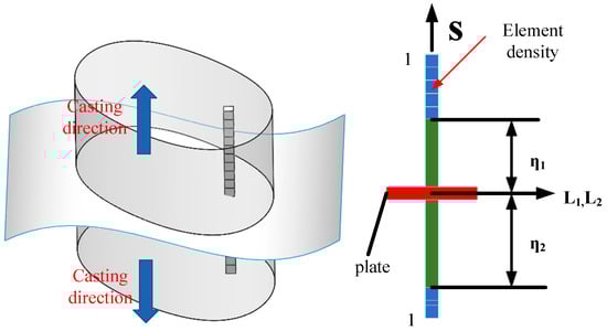
Figure 1.
Illustrative sketch of the curved-plate structure with double-sided stiffeners.
To determine the location of the reference plate, a set of design variables is defined. The height values of the reference plate center are equally distributed: . The coordinates are , and the spacing is . In this paper, cubic spline interpolation with natural boundary conditions is applied to determine the height of any element of the reference plate center whose expression is
where can be obtained by
where is computed by
In addition, and are given as follows:
where and are computed by
Through the above formulations, the specific position of the center of a series of reference plate centers in the X and Y directions can be determined.
The thickness of the reference plate is . Thus, when only considering the influence of the reference plate, the density of any element in the design domain can be obtained:
where is a normalized coordinate of the center point of any element in the Z direction, is the height of any element on the reference plate to the lower boundary of the design domain, and is the first Heaviside function, whose specific expression is as follows:
where the parameter determines the smoothness of the approximate function. The larger the value, the steeper the approximation, as shown in Figure 2.
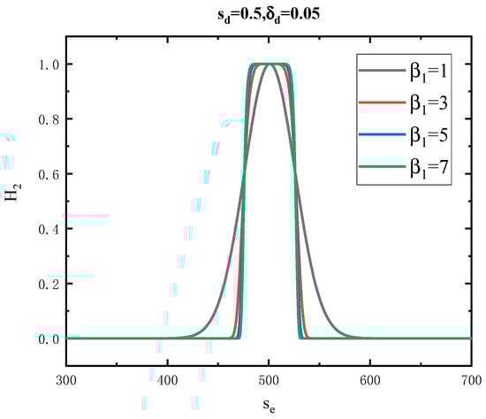
Figure 2.
The second smooth Heaviside function with different values.
Now, after the reference plate has been determined, the next step is to model the stiffeners. The direction of the stiffener is first determined, and sets of elements above and below the reference plate (usually judged by the position of the center point of the element) are regarded as two stiffeners. Here, four design values are defined: the design variable that describes the layout of the stiffeners above the reference plate , the design variable that describes the height of the stiffeners above the reference plate , the design variable that describes the layout of the stiffeners below the reference plate , and the design variable that describes the height of the stiffeners below the reference plate . Thus, when considering the influence of stiffeners, the density of any element is formulated as follows:
where
where is the normalized coordinate of the center point of any element above/below the reference plate; is the height of the j-th stiffener above/below the reference plate; is the second Heaviside function; and is the density of the j-th stiffener above/below the base surface which can be penalized to 0 or 1. Because the Heaviside function is a sudden-change function and its first derivative is discontinuous, in order to adopt a gradient optimization algorithm, it usually needs to be approximately smoothed. In this paper, the Sigmoid function commonly used in artificial neural network theory is used to approximate the Heaviside function, and the modified form is as follows:
where the parameter is similar to , which determines the smoothness of the approximate function, and the larger the value, the steeper the approximation, as is shown in Figure 3.
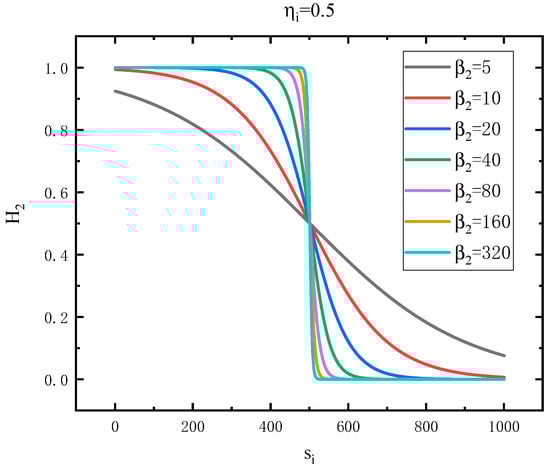
Figure 3.
The first smooth Heaviside function with different values.
When the two conditions of the stiffeners and the base plate are considered simultaneously, the relations of their values with the density of all elements are determined, as shown in Table 1.

Table 1.
The relationship between and X1, X2.
Therefore, as is shown in Figure 4, the density of all elements in the 3D design domain can be interpolated as follows:
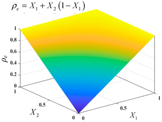
Figure 4.
The interpolation function for element density .
Now, Equation (11) is the final developed parameterization model for the curved-plate structure with double-sided stiffeners, and it is used to realize the topology optimization of such structures in the next section.
2.2. Topology Optimization Model
In this paper, the compliance optimization problem is considered. The optimization formulation is given as follows:
where is the compliance, is the displacement vector, is the external load vector, and is the global stiffness matrix, which can be assembled by
where is the element stiffness matrix and is the number of elements. is the lower limit of density to avoid the singularity of the global stiffness matrix; is the upper limit of density. is a penalization parameter, and is set as 3 in this paper. Because of only considering volume constraint in this paper, the constraint function can be expressed by
where is the element volume, is the allowed volume fraction, and is the total volume of the design domain.
3. Sensitivity Analysis
The sensitivity of the objective function with respect to the design values can be obtained by the chain rule as follows:
where is the number of elements in the design domain, and can be written as
In addition, the term can be formulated as
Also, is the sensitivity of the height of the reference plate to the equally distributed height of the reference plate , which can be expressed by
Now, , can be similarly written as follows:
Based on the relationship between and , say that
The term can be expressed by
According to Equations (1), (10), and (11), the sensitivity of the objective function to the design values by the chain rule can be obtained as follows:
where is the number of elements in a stiffener above the reference plate, is the number of elements in a stiffener below the reference plate, and is the sensitivity of compliance to element density, whose expression is
where is the displacement vector of the element and is the stiffness matrix of the element. is the sensitivity of the Heaviside function with respect to the design variable , which can be expressed by
The values of parameters and determine the size of the transition domain of the Heaviside function, so choosing reasonable values of parameters and is very influential to the optimization process. To determine their value, numerical experiments were carried out to show that the height of the stiffeners varied by 0.0001 steps from 0 to 1, and the other design variables were all 1. For different values, the curves of the objective function on the variable are shown in Figure 2.
4. Numerical Implementations
Next, the process of topology optimization with the parameterized methods is summarized. First of all, we need to determine the position of the reference plate by setting the initial design variable, and then substituting the initial design variable into cubic spline interpolation to obtain the height of the reference plate with a set of elements in the X direction. The height of each set of elements in the Y direction is the same, so the height of all elements on the reference plate can be obtained. The element density within the thickness of the reference plate is 1. The direction of the stiffeners is positive and negative in the Z direction. Secondly, the element density should be calculated by the parameterized optimization method, which is the key to the realization of the algorithm. Third, a new iterative process is started by updating the design variables through MMA. The specific optimization process is as follows:
Step 1: Initialize design variables. Determine the position of the base surface and set up the direction of the stiffeners and the maximum design variable change , maximum iterations , and the iteration counters , , and . Set up the system of equations and choose the filter method, etc.
Step 2: While and , then and go to Step 3, else go to Step 9.
Step 3: Calculate element density from design variables.
Step 4: Solve elastic problems.
Step 5: Calculate objective function and constraint function.
Step 6: Solve sensitivity.
Step 7: Update design variables based on MMA optimization algorithm.
Step 8: If , then and go to Step 2.
Step 9: Post-processing after optimization convergence.
5. Numerical Examples
Based on the topology optimization method presented above, the topology optimization design is carried out for two typical examples. In the examples, the material is isotropic, the elastic modulus is E = 1 MPa, and Poisson’s ratio is . The design domain is divided by a hexahedral eight-node grid. The interpolation parameters for the SIMP interpolation start at 1 and increase by 1 for every quarter of the operation. The maximum is 3. Sensitivity filtering is used to avoid the checkerboard phenomenon and grid dependence, and the filtering radius is 2.5. The design variables are updated based on the MMA algorithm. A parameter is introduced in order to describe the dispersion of the optimization results, which is
where is the element density and is the element volume. The smaller the value of , the closer the optimized element density is to the 0–1 distribution, and the better the optimization effect.
5.1. Example 1: Simply Supported Plate
In this section, the structure of a simply supported plate is designed, as shown in Figure 5, to obtain the optimal reference surface position, stiffener height, and layout simultaneously. The design range is a 192 × 192 × 128 cube, and the four edges of the lower end face are fixed in three directions. Vertical point loads are applied to the upper bottom, as shown in Figure 5. In order to better optimize the structure, select the element near the load and constraint as the undesignable domains.
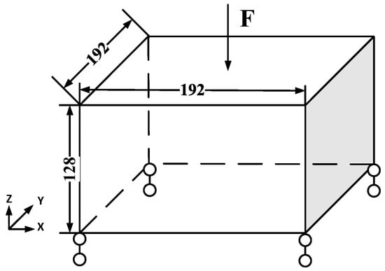
Figure 5.
The design domain of the simply supported plate structures.
First, the topological optimization results obtained by the four methods are shown in Figure 6 with a volume fraction of 40%. The red represents the reference plate, the green represents the stiffener structure, and the remaining colors are gray elements. Figure 6a is the result of the topology optimization under the condition where the reference plate is a flat plate and the height is fixed to 0.5. It can be seen that there are more gray elements around the reference plate, and the final objective function value is 328.8133. Figure 6b is the topological optimization result under the condition where the reference plate is a flat plate and the height is a design variable. It can be seen that there are fewer gray elements around the reference plate, and the final objective function value is 317.1167. Figure 6c is the topological optimization result under the condition where the reference plate is a curved plate interpolated by spline and both ends of the curved plate are fixed at 0.5. It can be seen that compared with the result of a flat plate, the structure is more reasonable and there are fewer gray elements. The final objective function value is 303.8884. Figure 6d is the topological optimization result under the condition where the reference plate is a curved plate interpolated by spline and both ends of the curved plate are highly free. Compared with the optimization results of the previous three methods, the final objective function value is smaller (294.7610), as shown in Table 2.
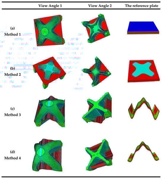
Figure 6.
Topologically optimized structures of the four methods. (a) Method 1: The reference plate is flat and its location in the height direction is fixed at 0.5. (b) Method 2: The reference plate is flat and its location in height direction is considered as a design variable. (c) Method 3: The reference plate is curved with its shape optimized but with fixed locations at the boundaries (fixed as 0.5). (d) Method 4: The reference plate is curved with its shape freely optimized, including the locations at the boundaries.
Table 2.
Initial and final values of the objective function for the considered four cases.
The iterative curves of the optimization process of the four methods are given in Figure 7. The small oscillation of the curve during the optimization iterative process is mainly caused by the changes in the values of β1 and β2. The sudden increase in the objective function near steps 100 and 200 is due to the increase in the penalty factor p. Through optimization, the four methods, respectively, reduce the objective function from the same initial value of 1201 to 328.81, 317.12, 303.89, and 294.76, corresponding to increases in structural stiffness of 3.65, 3.79, 3.95, and 4.07 times, respectively. Thus, it can be seen from these results that the optimized result for Method 4 is the best, where the reference plate is curved with its shape freely optimized, including the location at the boundaries. Furthermore, optimized structures with different volume fractions are also provided, as shown in Figure 8. It can be observed that there are differences in the optimized results with different volume fractions, indicating that volume fraction can influence the optimal structure.
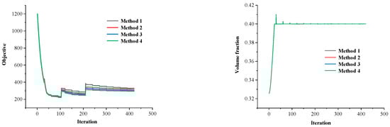
Figure 7.
Iteration curves of objective function and constraint function.
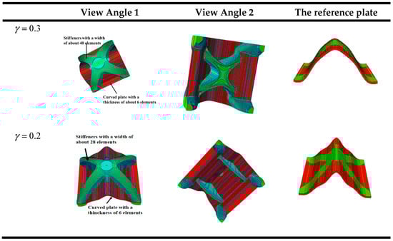
Figure 8.
Optimized structures with different volume fractions.
Also, it should be noted that the computational efficiency of the proposed method is poorer than the existing H-DGTP-based method (for the above considered examples, the computational efficiency of the proposed method is approximately 20% to 30% lower than for existing methods), and this is because the new method has far more design variables, which will increase the computational time of the sensitivity analysis and optimization solver.
5.2. Cantilever Beam
In this section, the structure of the cantilever beam is designed, as shown in Figure 9, to obtain the optimal base reference position, stiffener height, and layout simultaneously. The design domain is a 384 × 64 × 128 cube, whose left side is fixed in three directions. Vertical point loads are applied to the right end of the reference surface, as shown in Figure 9. The discrete domain of an eight-node brick element is used for finite element analysis. The volume fraction is set to 40%.
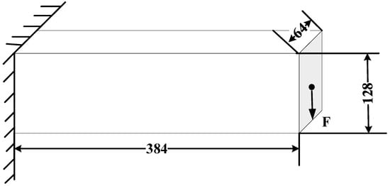
Figure 9.
The design domain of the cantilever beam example.
As shown in Figure 10, the optimized results indicate that the shape of the optimal structure plate is curved rather than flat, validating the necessity for the optimization of the stiffened plate’s shape. Additionally, it can be observed that there are stiffening structures on both sides of the plate. Therefore, it can be concluded that, through the method proposed in this paper, stiffened plates with stiffeners on both sides can be obtained. This once again confirms the effectiveness of the method proposed in this paper.
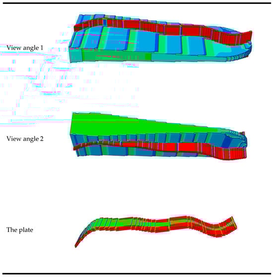
Figure 10.
Different view angles of the optimized structures.
6. Conclusions
This paper proposed an improved H-DGTP method (Heaviside-function-based directional growth topology parameterization method) for stiffened plate structures. This enhanced approach extends the method’s scope from planar and single-sided stiffened plates to curved and double-sided ones. It specifically considers the positioning and shape of curved panels, along with the arrangement and height of stiffeners, as design variables. Emphasizing structural stiffness as the optimization objective, a topology optimization model is established for double-sided curved stiffened plate structures, followed by a comprehensive sensitivity analysis. Numerical examples demonstrate that optimizing both the position and shape of the plate, along with the layout and height of the stiffeners on both sides of the curved plate simultaneously, yields greater stiffness than optimizing only a subset of these variables. This underscores the necessity and effectiveness of the proposed method.
In this article, only the mechanical stiffness optimization problem is considered. In the future, this method will be extended to more complex design problems, such as thermomechanical coupling and thermo-vibration coupling problems.
Details on the numerical implementation for replicating the results are provided in Section 4, with the pseudo-code and the optimization parameters. The design problems, mesh size, and boundary conditions are given in Section 5. If the information provided in the paper is not enough, we sincerely welcome scientists or interested parties to contact us for further explanation.
Author Contributions
Methodology, K.X., F.Z., Y.L. and Q.L.; Validation, K.X., F.Z., Y.L. and Q.L.; Writing—original draft, K.X. and F.Z.; Writing—review & editing, Y.L. and Q.L. All authors have read and agreed to the published version of the manuscript.
Funding
This work was financially supported by the National Natural Science Foundation of China (Grant Nos. 52375253 and 12202154) and the Dreams Foundation of Jianghuai Advance Technology Center (No. 20240102).
Data Availability Statement
The original contributions presented in the study are included in the article, further inquiries can be directed to the corresponding authors.
Conflicts of Interest
The authors declare that they have no conflicts of interest.
References
- Zhang, S.; Norato, J.A. Optimal design of panel reinforcements with ribs made of plates. J. Mech. Des. 2017, 139, 081403. [Google Scholar] [CrossRef]
- Hao, P.; Wang, B.; Tian, K.; Li, G.; Du, K.; Niu, F.J. Efficient optimization of cylindrical stiffened shells with reinforced cutouts by curvilinear stiffeners. AIAA J. 2016, 54, 1350–1363. [Google Scholar] [CrossRef]
- Zhu, J.-H.; Gu, X.-J.; Zhang, W.-H.; Beckers, P. Structural design of aircraft skin stretch-forming die using topology optimization. J. Comput. Appl. Math. 2013, 246, 278–288. [Google Scholar] [CrossRef]
- Chen, B.; Liu, G.; Kang, J.; Li, Y. Design optimization of stiffened storage tank for spacecraft. Struct. Multidiscip. Optim. 2007, 36, 83–92. [Google Scholar] [CrossRef]
- Ding, Y.; Zhou, Z.; Wang, Z.; Liu, H.; Wang, K. Bionic Stiffener Layout Optimization with a Flexible Plate in Solar-Powered UAV Surface Structure Design. Appl. Sci. 2019, 9, 5196. [Google Scholar] [CrossRef]
- Shroff, S.; Acar, E.; Kassapoglou, C. Design, analysis, fabrication, and testing of composite grid-stiffened panels for aircraft structures. Thin-Walled Struct. 2017, 119, 235–246. [Google Scholar] [CrossRef]
- Ji, J.; Ding, X.; Xiong, M.J. Optimal stiffener layout of plate/shell structures by bionic growth method. Comput. Struct. 2014, 135, 88–99. [Google Scholar] [CrossRef]
- Kaufmann, M.; Zenkert, D.; Mattei, C. Cost optimization of composite aircraft structures including variable laminate qualities. Compos. Sci. Technol. 2008, 68, 2748–2754. [Google Scholar] [CrossRef]
- Ahn, H.-K.; De Berg, M.; Bose, P.; Cheng, S.-W.; Halperin, D.; Matoušek, J.; Schwarzkopf, O. Separating an object from its cast. Comput.-Aided Des. 2002, 34, 547–559. [Google Scholar] [CrossRef]
- Xia, Q.; Shi, T.; Wang, M.Y.; Liu, S. A level set based method for the optimization of cast part. Struct. Multidiscip. Optim. 2010, 41, 735–747. [Google Scholar] [CrossRef]
- Li, B.; Huang, C.; Xuan, C.; Liu, X. Dynamic stiffness design of plate/shell structures using explicit topology optimization. Thin-Walled Struct. 2019, 140, 542–564. [Google Scholar] [CrossRef]
- Zhu, J.-H.; Zhang, W.-H.; Xia, L. Topology optimization in aircraft and aerospace structures design. Arch. Comput. Methods Eng. 2016, 23, 595–622. [Google Scholar] [CrossRef]
- Li, B.; Hong, J.; Liu, Z. Stiffness design of machine tool structures by a biologically inspired topology optimization method. Int. J. Mach. Tools Manuf. 2014, 84, 33–44. [Google Scholar] [CrossRef]
- Bendsøe, M.P.; Kikuchi, N. Generating optimal topologies in structural design using a homogenization method. Comput. Methods Appl. Mech. Eng. 1988, 71, 197–224. [Google Scholar] [CrossRef]
- Bendsøe, M.P.; Sigmund, O. Topology Optimization—Theory, Methods, and Applications; Springer: Berlin/Heidelberg, Germany, 2003. [Google Scholar]
- Wang, M.Y.; Wang, X.M.; Guo, D.M. A level set method for structural topology optimization. Comput. Methods Appl. Mech. Eng. 2003, 192, 227–246. [Google Scholar] [CrossRef]
- Xie, Y.M.; Steven, G.P. A simple evolutionary procedure for structural optimization. Comput. Struct. 1993, 49, 885–896. [Google Scholar] [CrossRef]
- Wein, F.; Dunning, P.D.; Norato, J.A. A review on feature-mapping methods for structural optimization. Struct. Multidiscip. Optim. 2020, 62, 1597–1638. [Google Scholar] [CrossRef]
- Gersborg, A.R.; Andreasen, C.S. An explicit parameterization for casting constraints in gradient driven topology optimization. Struct. Multidiscip. Optim. 2011, 44, 875–881. [Google Scholar] [CrossRef]
- Wang, Y.; Kang, Z. Structural shape and topology optimization of cast parts using level set method. Int. J. Numer. Methods Eng. 2017, 111, 1252–1273. [Google Scholar] [CrossRef]
- Xu, B.; Han, Y.S.; Zhao, L.; Xie, Y.M. Topology optimization of continuum structures for natural frequencies considering casting constraints. Eng. Optim. 2019, 51, 941–960. [Google Scholar] [CrossRef]
- Bojczuk, D.; Szteleblak, W. Optimization of layout and shape of stiffeners in 2D structures. Comput. Struct. 2008, 86, 1436–1446. [Google Scholar] [CrossRef]
- Luo, J.; Gea, H.C. Optimal stiffener design for interior sound reduction using a topology optimization based approach. J. Vib. Acoust. 2003, 125, 267–273. [Google Scholar] [CrossRef]
- Zhang, H.; Ding, X.; Dong, X.; Xiong, M. Optimal topology design of internal stiffeners for machine pedestal structures using biological branching phenomena. Struct. Multidiscip. Optim. 2018, 57, 2323–2338. [Google Scholar] [CrossRef]
- Cheng, K.-T.; Olhoff, N. An investigation concerning optimal design of solid elastic plates. Int. J. Solids Struct. 1981, 17, 305–323. [Google Scholar] [CrossRef]
- Rais-Rohani, M.; Lokits, J. Reinforcement layout and sizing optimization of composite submarine sail structures. Struct. Multidiscip. Optim. 2007, 34, 75–90. [Google Scholar] [CrossRef]
- Krog, L.A.; Olhoff, N. Optimum topology and reinforcement design of disk and plate structures with multiple stiffness and eigenfrequency objectives. Comput. Struct. 1999, 72, 535–563. [Google Scholar] [CrossRef]
- Liu, S.; Li, Q.; Chen, W.; Hu, R.; Tong, L. H-DGTP—A Heaviside-function based directional growth topology parameterization for design optimization of stiffener layout and height of thin-walled structures. Struct. Multidiscip. Optim. 2015, 52, 903–913. [Google Scholar] [CrossRef]
- Sun, Z.; Wang, Y.; Gao, Z.; Luo, Y. Topology optimization of thin-walled structures with directional straight stiffeners. Appl. Math. Model. 2023, 113, 640–663. [Google Scholar] [CrossRef]
- Huang, L.; Gao, T.; Sun, Z.; Wang, B.; Tian, K. An integrated topology and shape optimization framework for stiffened curved shells by mesh deformation. Eng. Comput. 2023, 40, 1771–1793. [Google Scholar] [CrossRef]
- Sun, Y.; Zhou, Y.; Ke, Z.; Tian, K.; Wang, B. Stiffener layout optimization framework by isogeometric analysis-based stiffness spreading method. Comput. Methods Appl. Mech. Eng. 2022, 390, 114348. [Google Scholar] [CrossRef]


Disclaimer/Publisher’s Note: The statements, opinions and data contained in all publications are solely those of the individual author(s) and contributor(s) and not of MDPI and/or the editor(s). MDPI and/or the editor(s) disclaim responsibility for any injury to people or property resulting from any ideas, methods, instructions or products referred to in the content. |
© 2024 by the authors. Licensee MDPI, Basel, Switzerland. This article is an open access article distributed under the terms and conditions of the Creative Commons Attribution (CC BY) license (https://creativecommons.org/licenses/by/4.0/).