Article

Modeling and Control of the High-Voltage Terminal of a Tandem Van de Graaff Accelerator

by
Efrén Gutiérrez Ocampo
1,2,
Belem Saldivar
3,*,
Juan Carlos Ávila Vilchis
1 and
Otniel Portillo-Rodríguez
1
1
Facultad de Ingeniería, Universidad Autónoma del Estado de México, Instituto Literario No. 100 Ote., Toluca 50130, Estado de México, Mexico
2
Instituto Nacional de Investigaciones Nucleares, Carretera Mexico-Toluca S/N, Ocoyoacac 52750, Estado de México, Mexico
3
Departamento de Control Automático, Centro de Investigación y de Estudios Avanzados del Instituto Politécnico Nacional, Av. Instituto Politécnico Nacional 2508, Ciudad de México 07360, Mexico
*
Author to whom correspondence should be addressed.
Mathematics 2024, 12(15), 2335; https://doi.org/10.3390/math12152335
Submission received: 8 June 2024 / Revised: 17 July 2024 / Accepted: 22 July 2024 / Published: 26 July 2024
(This article belongs to the Special Issue Advanced Control of Complex Dynamical Systems with Applications)

Abstract

:
This paper presents a mathematical model derived from an equivalent electrical circuit to describe the dynamic behavior of the high-voltage terminal of a tandem Van de Graaff accelerator. Two approaches are presented for modeling the transit time of the current flowing through the corona needles. The first one considers an equivalent self-inductance in the corona triode, whereas, in the second one, the transit time is represented by a delay in the corona current. The validation of the proposed models was carried out through experimental tests developed at the National Nuclear Research Institute of Mexico. Furthermore, two strategies for controlling the slow variations of the terminal voltage limited by the slow response of the control loop based on corona discharge are evaluated: a Proportional–Integral–Derivative controller and a sliding mode controller. The Root-Mean-Squared Error calculation leads to the conclusion that both control strategies are suitable for regulating the voltage at the accelerator potential terminal. However, the sliding mode controller leads to an overshoot-free response and a shorter settling time.

1. Introduction

Particle accelerators increase the energy of ions to make them collide at relatively high speeds against the atoms of some material under study and generate a characteristic response, which allows analyzing their properties. Some examples of the applications of a tandem Van de Graaff accelerator are analyses of environmental samples and material analysis like radiation damage or nuclear reactions by using different analytical techniques such as Particle-Induced X-ray Emission (PIXE) or Rutherford Backscattering Spectrometry (RBS) [1].
Acceleration of particles depends entirely on the voltage at the accelerator terminal, which determines the velocity of the particle beam. This velocity dictates the intensity of the magnetic field required by the analyzing magnet to steer the beam towards the target chamber. Thus, the terminal voltage not only influences the acceleration of the beam, but also its tuning. Stabilizing the voltage at the accelerator terminal is a crucial task since it ensures that the voltage remains constant, thereby producing a mono-energetic particle beam that can be used in a variety of experimental setups.
Over the years, several techniques have been proposed for stabilizing the voltage at the terminal in electrostatic particle accelerators. The methods and technologies for implementing these strategies have also significantly evolved. In the last six decades, we have seen the emergence of discrete solid-state devices such as diodes and transistors for this purpose [2,3]. These devices were followed by more advanced devices like operational amplifiers [4,5,6,7,8]. In recent reports, it has been observed that there is a growing inclination towards digital circuits, particularly microcontrollers, which utilize Analog-to-Digital Converters (ADC), and Digital-to-Analog Converters (DAC) [9,10,11].
Different control strategies have been reported for terminal voltage regulation. Among them, we can mention proportional compensators in phase advance [2,3,5], Proportional–Integral (PI) [4] or Proportional–Integral–Derivative (PID) controllers [11], and predictive-based control strategies [9]. In these works, fluctuations up to ±1 kV in SLIT mode have been reported [7].
There are various techniques to regulate the voltage at the terminal: one involves using the corona needles’ discharge process through the control grid of a vacuum tube. Voltage regulation can also be achieved by controlling the load band current source connected to the terminal in Van de Graaff-type accelerators or by controlling the charge chains of the terminal potential in Pelletron-type accelerators [2,7,8,10].
An essential aspect to take into account in the analysis of the behavior of the accelerator is the transit time in the corona discharge current (explained in detail in Section 3) [2,3]. It should be mentioned that, in some of the reported works, this transit time is not considered.
This paper presents a mathematical model of the terminal of a tandem Van de Graaff accelerator that considers the transit time in the corona discharge current. This transit time is represented as an equivalent self-inductance in the corona triode. Also, for comparison purposes, this transit time is modeled as a delay in the corona current. Experimental tests were carried out using the Van de Graaff tandem accelerator at the National Institute of Nuclear Research of Mexico to assess the accuracy of the proposed models.
Furthermore, two strategies for controlling the voltage at the terminal of the accelerator were analyzed: a PID controller and a sliding mode controller (SMC). Numerical simulations were conducted to verify the effectiveness of these controllers in regulating the terminal voltage.
The main contribution of the paper is the experimental validation of the proposed mathematical models derived from an equivalent electrical circuit of the high-voltage terminal. Besides, we have found that, with the PID and SMC controllers, better results than those reported in previous works can be obtained, since the steady-state voltage fluctuations are smaller than ± 1 kV.
The rest of the paper is organized as follows. Section 2 describes the main characteristics of the tandem Van de Graaff accelerator, as well as the operation modes of the Terminal Potential Stabilizer. Section 3 presents the mathematical model of the system, considering the aforementioned approaches to represent the transit time of the corona discharge current. Section 4 presents two different control strategies for the voltage stabilization of the accelerator terminal: PID control and SMC. Finally, in Section 5, some concluding remarks are given.

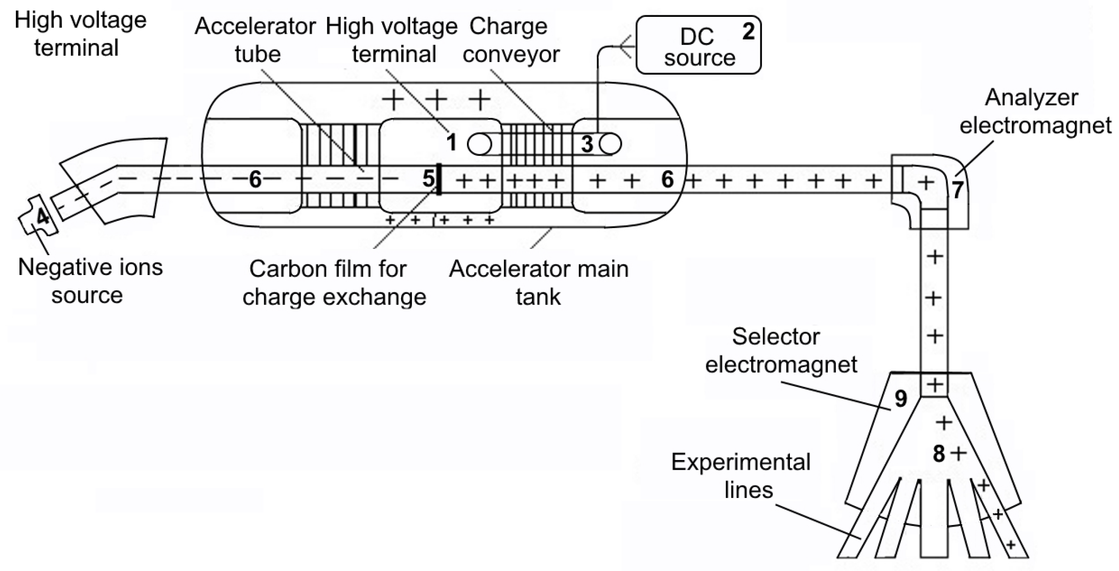
2. Tandem Van de Graaff Accelerator: General Overview

A scheme of the tandem Van de Graaff accelerator is shown in Figure 1. The operation principle is described below. The high-voltage terminal (1) is a fundamental component for the acceleration of particles. It is charged by a Van de Graaff system, consisting of a direct current source (2) and a belt (3), which transports the charge to the high-voltage terminal (in tandem Van de Graaff accelerators, a voltage of up to 6 MV is produced). A beam of negative ions is produced in an ion source (4) [12]; these negative ions are accelerated by the voltage applied to the high-voltage terminal. The terminal has a positive potential (1–6 MV), reaching a charge exchange channel (5) located at its central part, where it loses electrons, transforming them into positive ions, which are repelled and accelerated towards the other end of the acceleration tube (6). The particles leave the accelerator with an energy of approximately twice the voltage of the terminal. Subsequently, the particle beam passes through the analyzer electromagnet (7) to remove particles with charge states that are not required. Finally, the beam is directed to an experimental line (8) using a selector electromagnet (9) [13,14].
The function of the Terminal Potential Stabilizer (TPS) is to ensure that the voltage at the terminal remains constant and produces a mono-energetic particle beam [15].
The main components of the TPS and its associated elements, shown in Figure 2, are briefly described below:
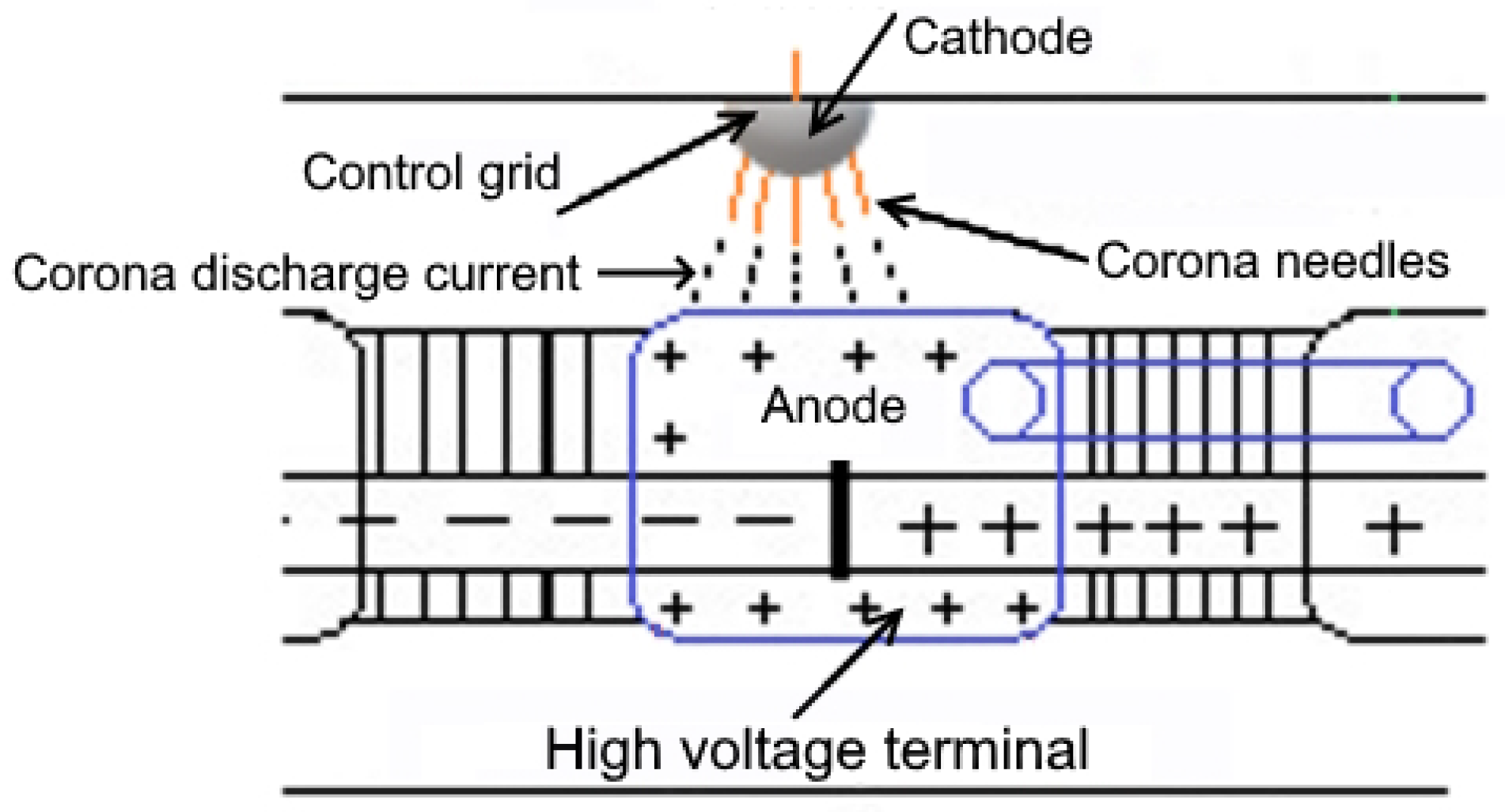
  • Corona needles drain current from the terminal potential and, thus, vary its voltage.
  • The generating voltmeter measures the terminal voltage in direct current (DC).
  • The Pick-Off Capacitor (POC) measures voltage variations in Alternating Current (AC).
  • SLITs monitor the position of the beam downstream of the analyzer electromagnet.
  • The high-voltage terminal produces a high voltage that allows the acceleration of the particles (in the remainder of the document, the term “terminal” refers to the high-voltage terminal).
  • The direct current source performs the transfer of the charge to the the terminal.
  • The analyzer electromagnet behaves as a filter, which selects particles of a given energy.
Figure 2. Tandem Van de Graaff accelerator TPS and associated components.
Mathematics 12 02335 g002
The TPS operates in the following basic modes:
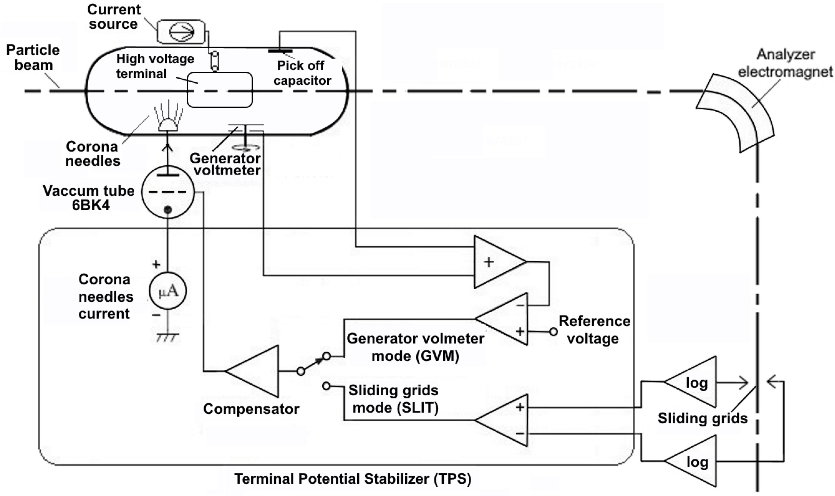
  • Generating voltmeter mode (GVM): This mode is used when it is desired to set the terminal voltage to a specific value given by a reference signal associated with the energy of the particles to be accelerated. In this mode, a fast feedback signal from the POC is used to reduce the short-term ripple in combination with a slow feedback signal from the voltage measured by the generating voltmeter. A compensator provides a signal to control the current drained through the corona needles using a 6BK4 vacuum tube control grid (Radio Corporation of America (RCA), Harrison, NJ, USA.). The current drained through the corona needles provides the voltage control at the accelerator terminal.
  • SLIT mode: This mode is put into operation when the particle beam is present after the analyzer electromagnet, which generates a current whose value is proportional to the beam position upon colliding with the SLITs. Once this position is monitored, it can be controlled by increasing or decreasing the terminal voltage by draining current from the terminal through the corona needles.
  • Automatic mode: This mode allows an automatic switching between the GVM and the SLIT mode, depending mainly on the current in the SLITs. If the value of a current is greater than a previously set value on the SLITs, the system remains in SLIT mode. Otherwise, if the value of the current is less than that of the SLITs, the system switches to GVM mode, where the user can manually vary the terminal voltage until the beam current required to switch to SLIT mode is obtained.

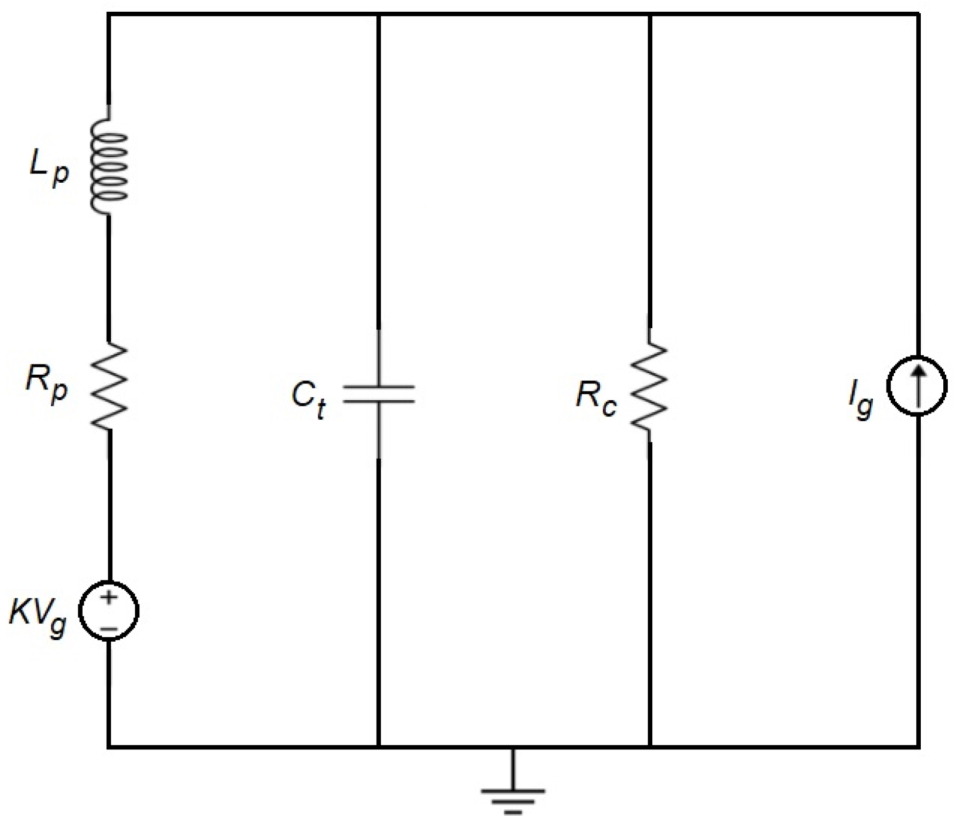
3. Mathematical Modeling

As mentioned before, the transit time of the corona triode discharge current used to regulate the terminal voltage, hereinafter denoted by τ , is a crucial aspect to be considered in the mathematical model of the system under study. The transit time of the corona triode is the time required by the charge carriers to cross the discharge path (see Figure 3). This time depends on the cathode–anode distance, the inertia of the charge carriers, the dielectric gas used as an insulator, as well as the pressure of the gas. Both electrons and ions contribute to the charge transport, although the transit time for a positive potential at the terminal is determined primarily by the negative ions. Transit times of approximately 30 ms have been reported in the literature for accelerators of this type [2,3,16].
The phase shift method is used to determine the transit time τ . A low-frequency sinusoidal signal is put on the grid of the triode 6BK4. The phase shift ϕ t r between the signal of the pick-up amplifier and the signal on the anode of the 6BK4 is measured using an oscilloscope. From the measured phase shift ϕ t r , the transit-time is calculated as [16]:
τ = Δ ϕ t r f · 360
where
Δ ϕ t r = ϕ t r 90
and f is the frequency in Hertz. The 90 subtracted from the measured phase shift ϕ t r corresponds to the contribution to the phase shift due to the terminal capacitance C t . From Equations (1) and (2), transit times of 12 ms to 26 ms were obtained, for a distance between the corona needle and the terminal ranging from 20 to 80%.
Two different approaches were considered for describing the transit time of the corona discharge current. The first one considers an equivalent self-inductance in the corona triode. In the second one, the transit time is represented as a delay in the corona current.

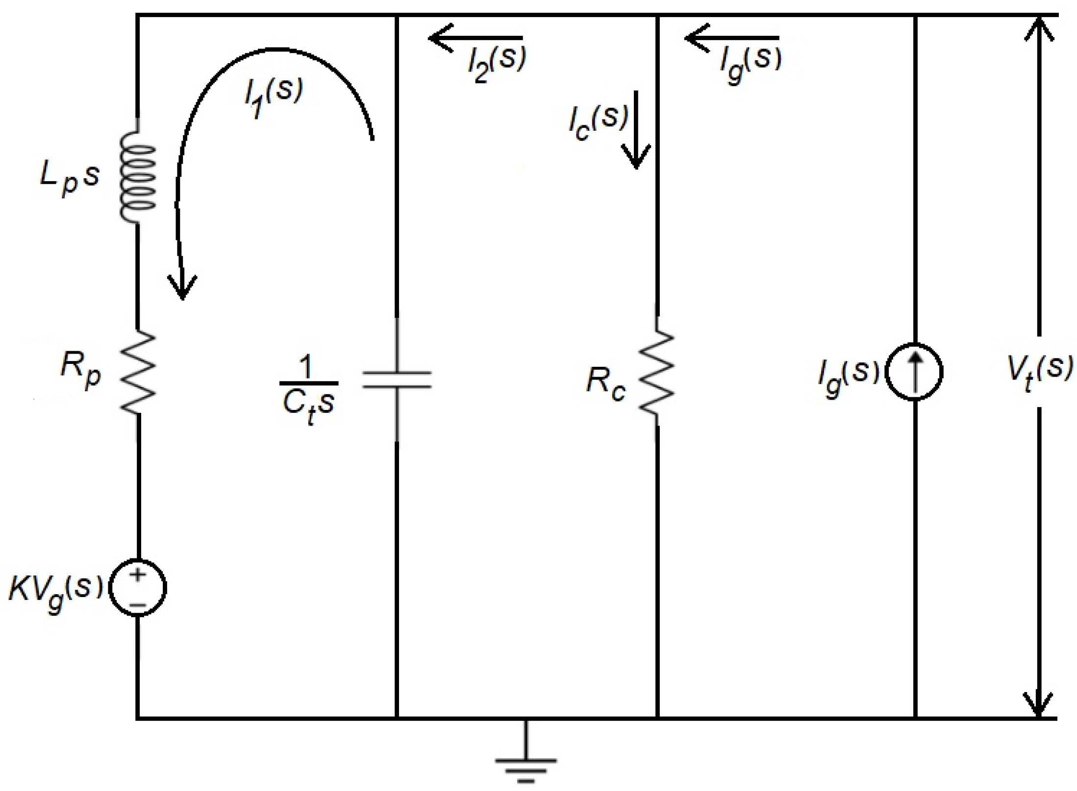
3.1. Model Considering an Equivalent Self-Inductance of the Corona Triode

An electrical circuit representing the terminal of the tandem Van de Graaff accelerator [16] is shown in Figure 4. The circuit consists of a voltage source V g representing the corona triode in series with the control triode, that is the vacuum valve 6BK4 (Radio Corporation of America (RCA), Harrison, NJ, USA), and a dimensionless amplification factor K, which is defined as the product of the amplification factor of both triodes. The internal resistance R p and the equivalent Self-Inductance of the Corona Triode (SICT) L p are in series with this source. The terminal capacitance C t and the column resistance R c make up the external load of this circuit. The terminal charge current is represented by the current source I g .
The electrical circuit shown in Figure 4 is represented in the frequency domain, as shown in Figure 5. This representation allows obtaining the mathematical model of the accelerator that relates the voltage at the terminal V t ( s ) as a function of the load current I g ( s ) and the control voltage K V g ( s ) , which are the inputs of the system.
This model is derived as follows. From the circuit shown in Figure 5, the equations that describe the dynamic behavior of the system are obtained by assuming initial conditions equal to zero. The voltage at the terminal V t ( s ) is given by:
V t ( s ) = I 2 ( s ) I 1 ( s ) C t s
From Equation (3), it can be observed that the output voltage V t ( s ) is a function of the currents I 2 ( s ) and I 1 ( s ) , which are, respectively, the load and discharge currents of the capacitor C t , which represents the terminal. These currents are given by:
I 1 ( s ) = V t ( s ) K V g ( s ) L p s + R p
and
I 2 ( s ) = I g ( s ) I c ( s )
where I g ( s ) is the current provided by the terminal charge source and I c ( s ) is the column current obtained from Equation (6).
I c ( s ) = V t ( s ) R c
To obtain the voltage at the terminal V t ( s ) as a function of the inputs defined by the voltage source K V g ( s ) and the load current source I g ( s ) , the superposition principle is applied. The system response is computed individually for each input, and then, the responses are added. The transfer function relating the voltage output V t ( s ) to the voltage input K V g ( s ) (considering I g ( s ) equal to zero) is shown in Equation (7).
V t ( s ) K V g ( s ) = R c C t L p R c s 2 + ( C t R c R p + L p ) s + ( R c + R p )
The transfer function relating the voltage output V t ( s ) to the load current input from the terminal I g ( s ) (considering the voltage input K V g ( s ) equal to zero) is given by Equation (8).
V t ( s ) I g ( s ) = L p R c s + R c R p C t L p R c s 2 + ( C t R c R p + L p ) s + ( R c + R p )
The voltage at the terminal V t ( s ) as a function of voltage K V g ( s ) and current I g ( s ) is described by Equation (9).
V t ( s ) = K V g ( s ) R c + I g ( s ) ( L p R c s + R c R p ) C t L p R c s 2 + ( C t R c R p + L p ) s + ( R c + R p )
The inductance L p , the resistance R p , and the amplification factor K change with respect to the terminal position of the corona needles. This distance is expressed as a percentage: when the corona tips are at the closest point to the terminal, this percentage is zero, and when they are at the farthest point from the terminal, it is 100%. The numerical values of these elements were calculated experimentally, according to the procedure presented in [3,16], and they are shown in Table 1. The capacitance C t = 81.49 × 10 12 F and the resistance R c = 33.91 × 10 9 Ω are considered constant for any position of the corona needles.
Numerical simulations of the proposed model were performed using Matlab® R2020a –Simulink. For the simulations, it was considered that the corona needles are 70% away from the terminal. Typical values for the accelerator operation were considered for the input signals, i.e., current I g ( s ) = 60 × 10 6 A. For the control voltage V g ( s ) , a square signal taking values from 0 to 8 V, and a period of 17 s was considered.
Figure 6 shows the simulation outcomes of the system described by Equation (9). The red curve shows the voltage at the terminal V t ( s ) ; the black curve shows the voltage generated by the current I g ( s ) ; the blue one shows the potential generated by the input voltage V g ( s ) . It is observed that the sum of the input current I g ( s ) and the control voltage V g ( s ) contributes to generating the terminal voltage.
To validate the proposed model, experimental tests were conducted in the tandem Van de Graaff accelerator at the National Institute of Nuclear Research of Mexico. This accelerator has the following main characteristics: It is manufactured by the company High Voltage Engineering Corporation (Burlington, MA, USA). It has an accelerator tank with a 6 MV high-voltage band-type generator. It is a Source of Negative Ions by Cesium Sputtering (SNICS).
Figure 7 compares the voltage V t ( s ) obtained through simulations of the terminal model (Sim) with the experimental results (Exp) obtained in the tandem Van de Graaff accelerator. The corona needles move away from the terminal in a percentage ranging from 20 to 80% of the total distance. The terminal voltage was measured using the generating voltmeter by connecting a Tektronix® digital oscilloscope model MSO2014B (Tektronix Inc., Shanghai, China) to this sensor.
In Figure 7, the red and black curves, representing the simulation and experiment results, respectively, are remarkably close. This close alignment instills confidence in the accuracy and reliability of our proposed model, reinforcing its potential to reproduce the behavior of the terminal voltage. Note that, at the beginning of the simulation ( t = 0 s), a significant discrepancy between the simulation and experimental results can be observed because the simulation was initialized considering zero initial conditions, placing the system in a transient regime, whereas the experimental data were collected during steady-state conditions of the accelerator. Note also that, at t = 35 s, there was a delay in the simulated response, primarily due to the effect of the inductance L p in the model. The inductance opposes current changes, causing a delay in the response. Now, for the sake of comparison, we adapted the model by considering that the corona’s current transit time is represented by a delay, instead of the equivalent SICT.

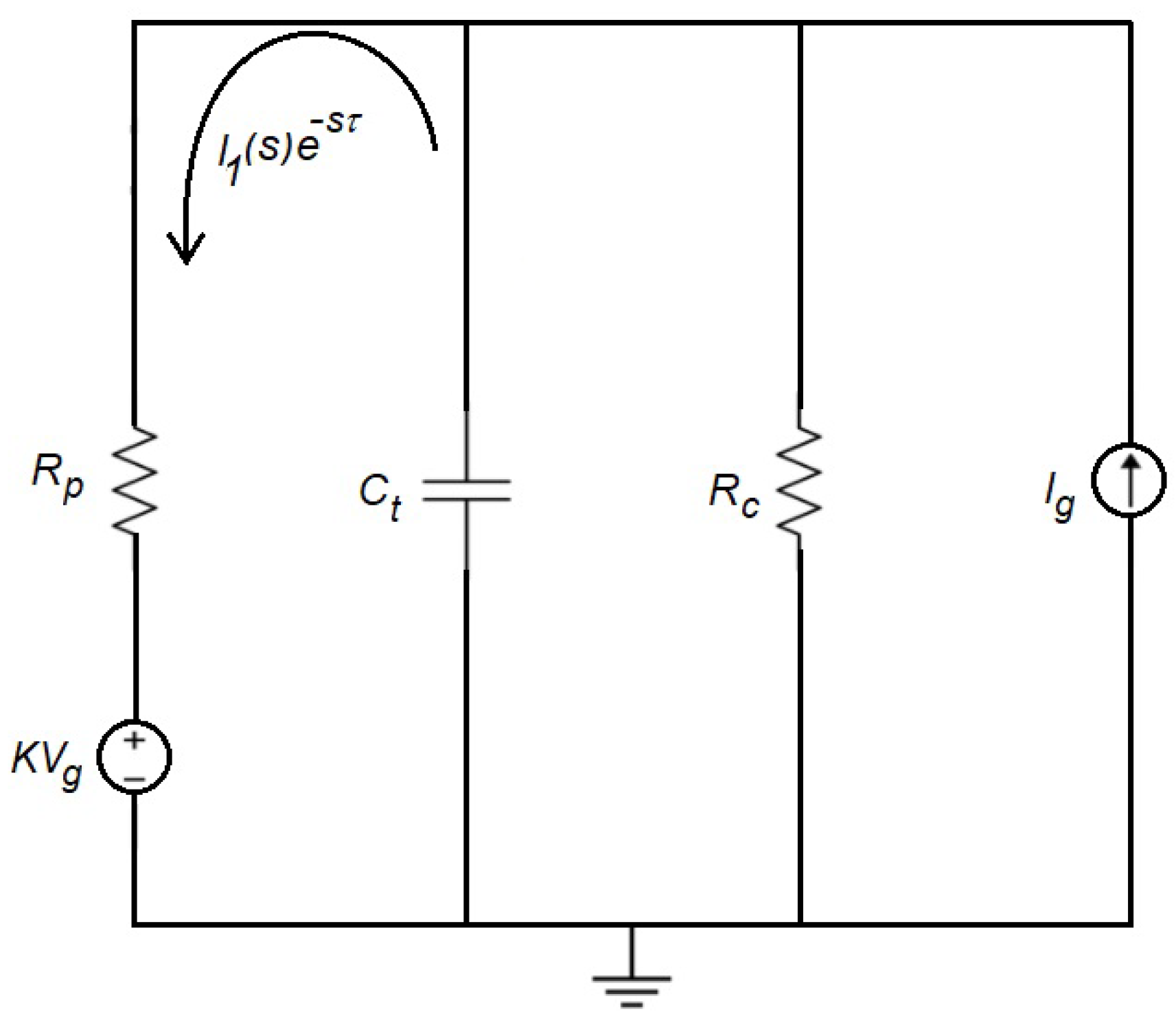
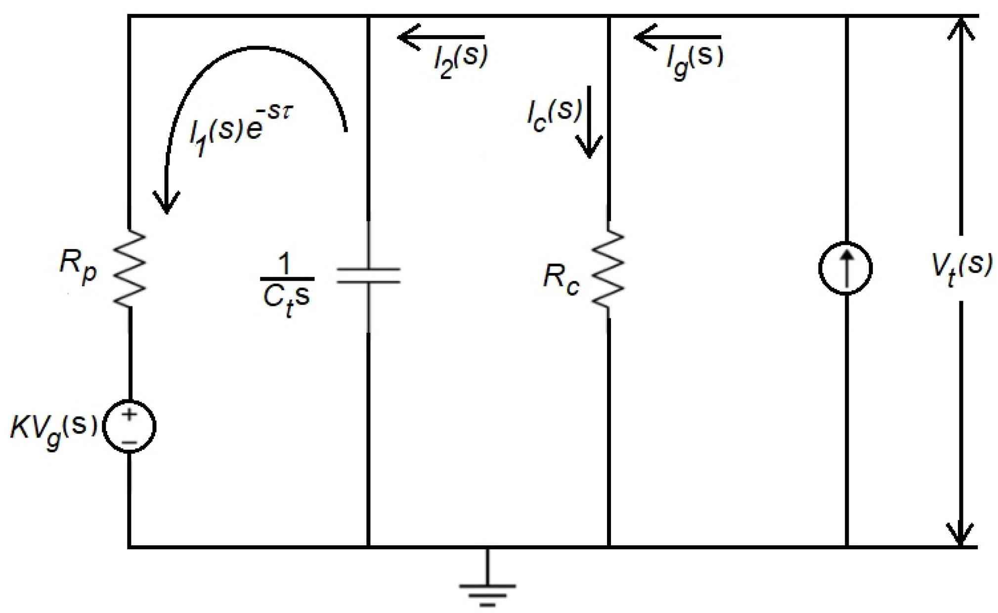
3.2. Model Considering a Delay to Represent the Transit of the Current through the Corona Triode

The mathematical model of the terminal of the tandem Van de Graaff accelerator that considers a delay τ corresponding to the transit time of the current through the corona triode (described in Section 3) is determined from the electrical circuit shown in Figure 8. The circuit elements V g , K, R p , C t , R c , and I g are the ones described in Section 3.1.
The equivalent electrical circuit in the frequency domain that describes the accelerator operation is shown in Figure 9. The mathematical model of the accelerator terminal behavior is obtained by defining the expression that relates the voltage V t ( s ) at the terminal as a function of the charge current I g ( s ) and the control voltage K V g ( s ) .
From the circuit in Figure 9, we obtain the equations describing the dynamic behavior of the system assuming initial conditions equal to zero. The voltage at the terminal V t ( s ) is given by Equation (10).
V t ( s ) = I 2 ( s ) I 1 ( s ) e s τ C t s
It is observed that Equation (10) is similar to Equation (3) only with the corresponding time delay τ in the current I 1 ( s ) . The currents I 1 ( s ) and I 2 ( s ) are defined in (11) and (12), respectively.
I 1 ( s ) = V t ( s ) K V g ( s ) R p
I 2 ( s ) = I g ( s ) I c ( s )
where I g ( s ) is the current provided by the terminal charge source and I c ( s ) is the column current obtained from Equation (13).
I c ( s ) = V t ( s ) R c
By applying the superposition principle, we obtain the voltage at the terminal V t ( s ) as a function of the inputs defined by the voltage source K V g ( s ) and the load current source I g ( s ) . The transfer function that relates the voltage output V t ( s ) to the voltage input K V g ( s ) (considering I g ( s ) equals zero) is given by Equation (14).
V t ( s ) K V g ( s ) = R c e s τ C t R c R p s + R p + R c e s τ
To obtain the transfer function relating the voltage output V t ( s ) to the load current input I g ( s ) of the terminal, the voltage input K V g ( s ) is considered equal to zero, resulting in Equation (15).
V t ( s ) I g ( s ) = R c R p C t R c R p s + R p + R c e s τ
The voltage at the terminal V t ( s ) as a function of voltage K V g ( s ) and current I g ( s ) is shown in Equation (16).
V t ( s ) = K V g ( s ) R c e s τ + I g ( s ) R c R p C t R c R p s + R p + R c e s τ
As before, numerical simulations and experimental tests were conducted to assess the reliability of this model.
Regarding the terminal voltage V t ( s ) , Figure 10 compares the simulation results (red curve) and the experimental outcomes (black curve) when the corona needles move away from the terminal potential by a percentage ranging from 20 to 80% of the total distance. Note that there is a significant discrepancy observed near t = 0 s, attributable to the same scenario described in Section 3.1 for the SICT model.
Table 2 shows the Root-Mean-Squared Error (RMSE) calculation of the simulation of the two models concerning the experimental data when the corona needles move away from the terminal by a percentage ranging from 20 to 80%. The RMSE measures the square root of the average of the squared deviations between two signals that highly discriminate their differences. An RMSE equal to zero (optimum value) occurs when the signals are identical; the smaller the value, the greater the similarity is. The RMSE is an approximation of the error’s standard deviation. The RMSE has the same units as the signals being analyzed, making it an intuitive metric for understanding the discrepancy between signals [17].
Note that the calculated RMSE is lower for the SICT model than the delayed model when the corona needles are separated by a distance between 20% and 80%. This indicates that the SICT model exhibits a closer resemblance to the actual behavior of the terminal than the delayed model.
With the proposed models, it was possible to reproduce the behavior of the terminal voltage of a real tandem Van de Graaff accelerator; the obtained results are similar to the results reported in other works (see, for example, Refs. [7,18]). From the data presented in Figure 7 and Figure 10, we can conclude that the voltages obtained using the model that takes into account the SICT have similar behavior to the one of the real accelerator terminal in the whole variation range of the corona needles’ distance. In contrast, the model that considers the transit time τ has noticeable deviations when the corona tips are at 50, 60, and 80%.
Based on the model that considers the equivalent SICT, two different control strategies for regulating the accelerator’s terminal voltage were examined: PID controller and SMC.

4. Terminal Voltage Regulation Problem
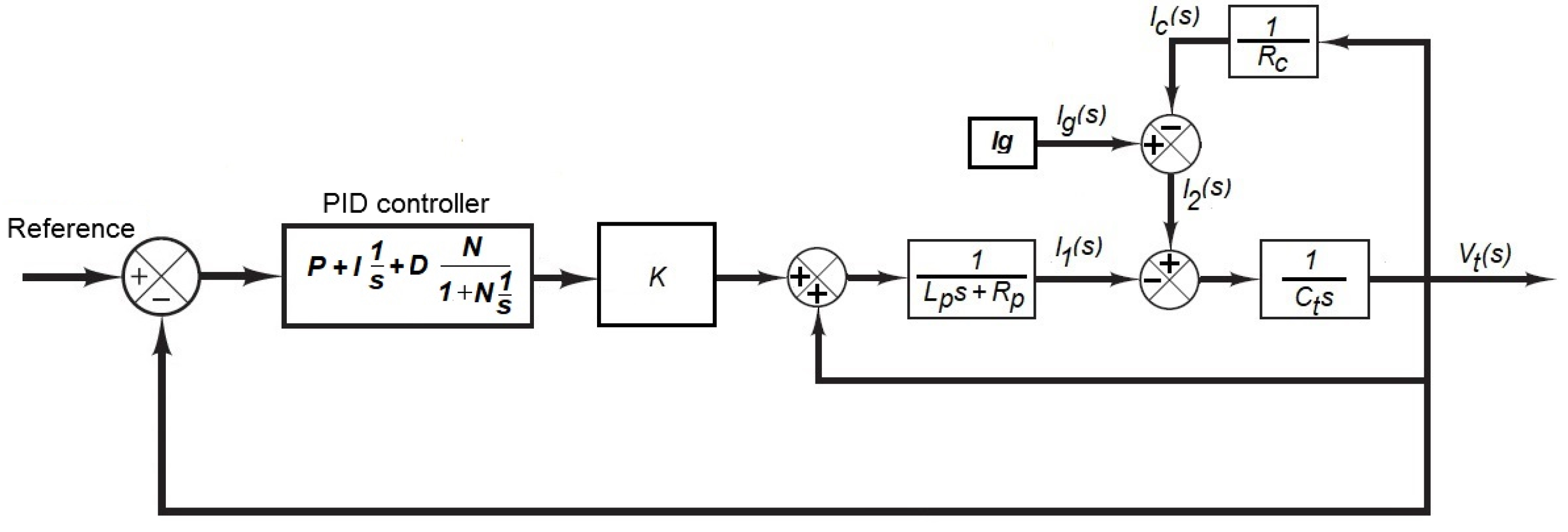
Two control strategies, PID and SMC, were evaluated to solve the voltage regulation problem. A PID controller was selected as the first option since this type of control is a classical strategy for solving the regulation task in dynamic systems [11,19]. On the other hand, SMC is a powerful strategy that can operate even in the presence of system disturbances that may arise from mechanical and electrical elements, for example problems with the electrical insulating, charge carrying, the mechanical movement of the generator belt, its spontaneous electrification, and the non-uniformity of the belt properties, especially variations in the belt joint, resulting in a significant disturbance of the high voltage at the accelerator terminal [9]. It is important to highlight that, in the forthcoming developments, ideal operating conditions and a well-conditioned accelerator are assumed.
The results obtained with each of the proposed controllers are presented in Section 4.1 and Section 4.2.

4.1. PID Controller

Figure 11 shows a block diagram of the system described by the model that considers the equivalent SICT in a closed loop with the PID controller defined by the transfer function (17).
G P I D ( s ) = P + I 1 s + D N 1 + N 1 s
The controller has Proportional P, Integral I, and derivative D gains and a first-order derivative filter with divider N.
It is important to note that the values of the parameters L p , R p , and K vary according to the distance of the corona needles, while the parameters I g , R c , and C t remain constant.
Table 3 shows the values of the PID control gains found using the Matlab® R2020a PID Tuner, considering different distances between the corona needles and the terminal, expressed in percentages from 10 to 90%.
Figure 12 shows the simulation results of the system in a closed loop with the PID controller (the controller gains are reported in Table 3). For this simulation, an input current of I g ( s ) = 60 × 10 6 A and a square signal voltage V g ( s ) with a period of 17 s were considered. The system response presented a maximum overshoot of M p = 5 % since the damping ratio was ξ = 0.82 (underdamped system). The overshoot decreased when the tips were closer to the terminal, having a damping ratio of ξ 1 (critically damped system). Observe that the settling time was t s 4.5 s. According to the results obtained in the transient response, it can be seen that, with the gains obtained for the PID controller, the voltage at the terminal V t can be adjusted from 400 kV to 1800 kV, which corresponds to a variation in the entire distance interval of the corona needles (10–90%) with a load current I g = 100 × 10 6 A. From the above, the PID controller can stabilize the voltage at the accelerator terminal over the entire distance range of the corona needles.

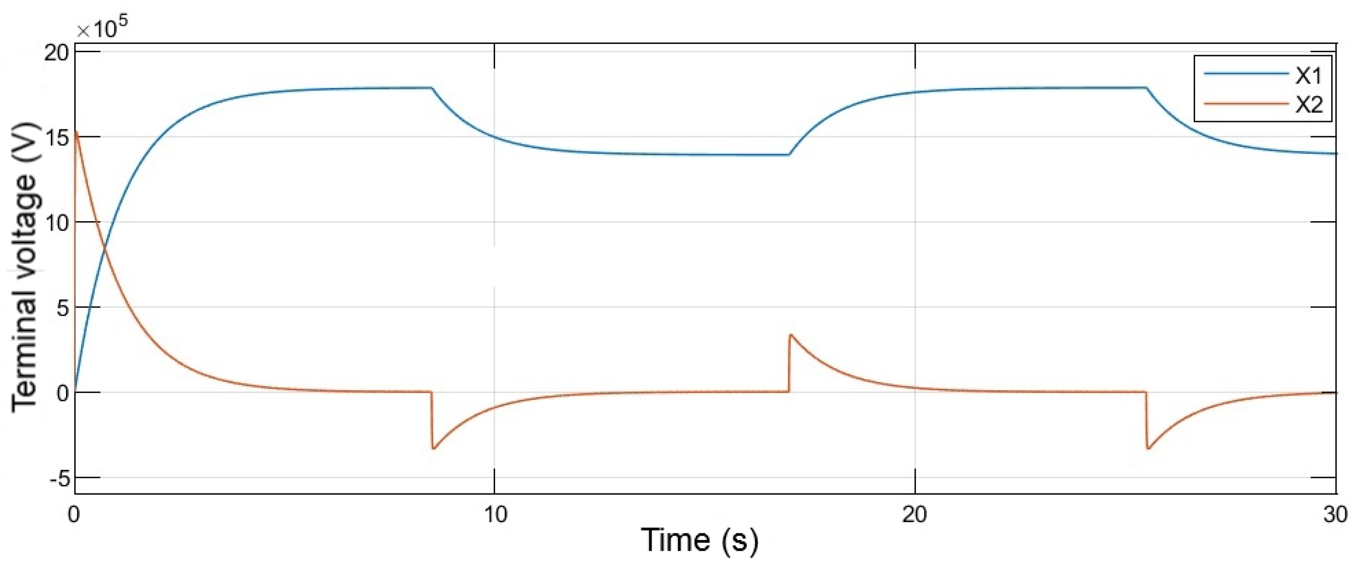
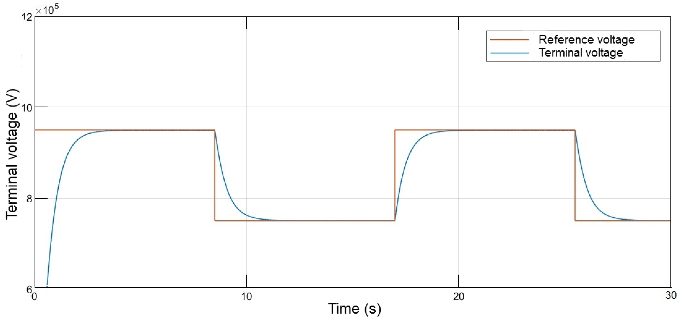
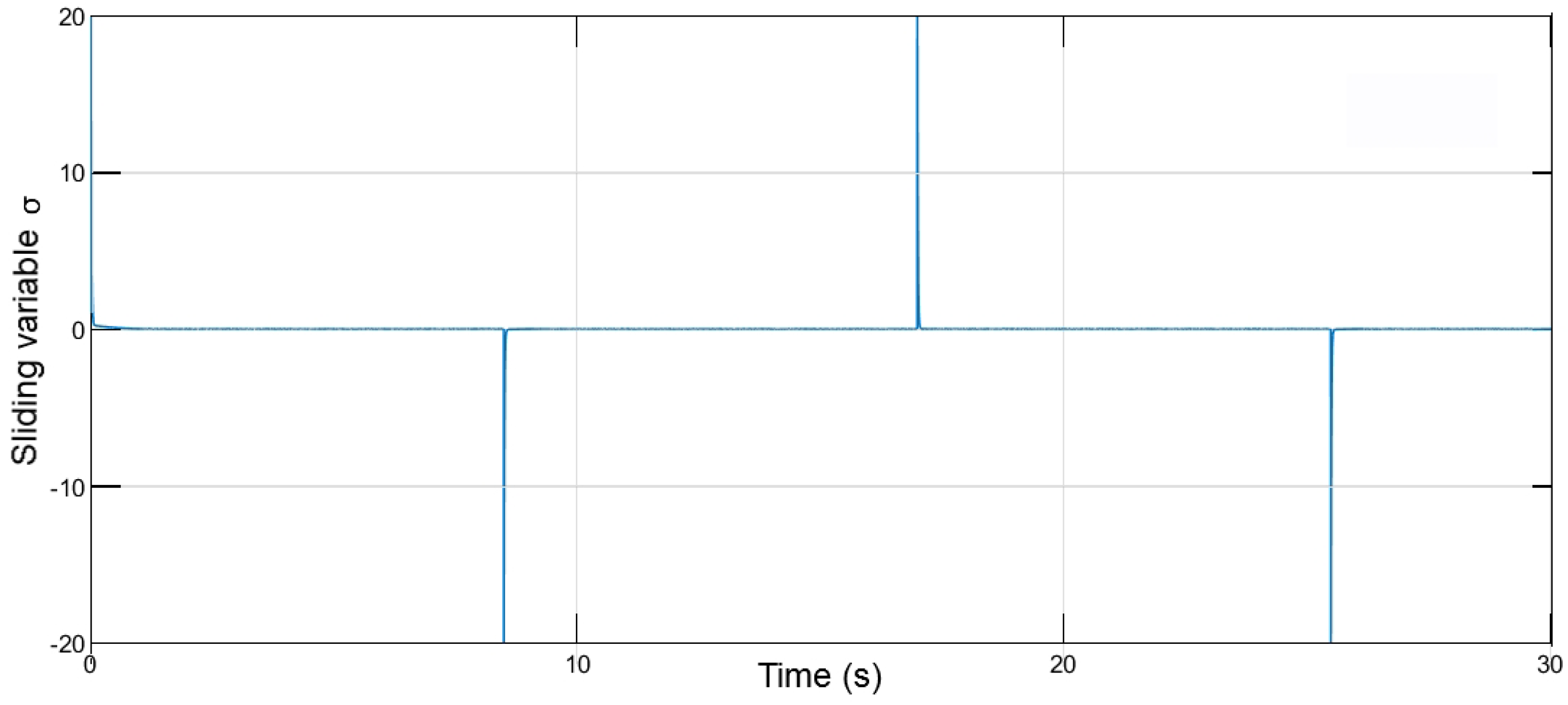
4.2. Sliding Mode Control

Output feedback tracking sliding mode control is a technique applied in a wide range of areas of control engineering [20,21,22,23]. One of the reasons for the success of the SMC approach is its robustness against disturbances. In addition, sliding mode controllers have other remarkable properties such as accuracy and easy tuning and implementation for linear and nonlinear systems with multiple inputs and outputs [21].
A sliding mode controller is proposed for the voltage regulation of a tandem Van de Graaff accelerator with the aim of maintaining the voltage at the terminal V t at a desired level by high-frequency switching of the 6BK4 power vacuum tube. For the design of this control, a state space time domain representation of the system is obtained, as shown in Section 4.2.1.

4.2.1. Time Domain Model of the Tandem Van de Graaff Accelerator Terminal

The voltage output V t ( s ) of the tandem Van de Graaff accelerator terminal as a function of the voltage K V g ( s ) and current I g ( s ) in the frequency domain is shown in Equation (9). By applying the inverse Laplace transform, one obtains:
C t L p R c V t ¨ + ( C t R c R p + L p ) V t ˙ + ( R c + R p ) V t = K V g R c + L p R c I g ˙ + R c R p I g
Since the terminal charge current I g is constant, then I g ˙ = 0 . From Equation (18), one obtains:
C t L p R c V t ¨ + ( C t R c R p + L p ) V t ˙ + ( R c + R p ) V t = K V g R c + R c R p I g
The system inputs are V g and I g . The charging current I g is constant, and the system is controlled through the voltage V g . The above system can be represented in the state space by defining the state variables x 1 ( t ) = V t and x 2 ( t ) = V t ˙ and output y as follows.
x 1 ˙ = x 2 x 2 ˙ = C 1 x 1 C 2 x 2 + C 3 u + C 4 I g y = x 1
where C 1 = ( R c + R p ) C t L p R c , C 2 = ( C t R c R p + L p ) C t L p R c , C 3 = K R c C t L p R c , C 4 = R c R p C t L p R c , and u = V g .
Figure 13 shows the numerical simulation results of the system defined in (20) when the corona needles are at a distance of 70%. The voltage reference signal is given by a square signal of amplitude 8 V and a period of 17 s. The system parameters are given by I g = 100 × 10 6 A, C 1 = 98.9543 s−2, C 2 = 111.8397 s−1, C 3 = 4.9211 × 10 6 s−2, and C 4 = 1.3762 × 10 12 Ω s−2.

4.2.2. Sliding Mode Control Design

System (20) can be represented as follows:
x ˙ 1 = x 2 x ˙ 2 = u ¯ + f ( x 1 , x 2 ) y = x 1
where u ¯ = C 3 u and f ( x 1 , x 2 ) = C 1 x 1 C 2 x 2 + C 4 I g . The problem involves designing a sliding mode control law u ¯ = u ¯ ( x 1 , x 2 ) to guarantee that the output y asymptotically follows a predefined reference y c , i.e., lim t ( y c ( t ) y ( t ) ) = 0 .
By defining the tracking error as e = ( y c ( t ) y ( t ) ) , the sliding variable is chosen as:
σ = e ˙ + c e c > 0
The next step is to design a conventional sliding mode control u ¯ that guarantees σ 0 in finite time and keeps it at zero. When the sliding variable reaches zero, the output tracking error e obeys the reduced first-order differential equation e ˙ = c e .
The time derivative of the sliding variable σ is given by
σ ˙ = y c ¨ + c y c ˙ f ( y , y ˙ ) c y ˙ u ¯
If we define
φ ( y , y ˙ ) = y c ¨ + c y c ˙ f ( y , y ˙ ) c y ˙ ,
then Equation (23) can be rewritten as follows:
σ ˙ = φ ( y , y ˙ ) u ¯
where y c , y ˙ c , and y ¨ c are known at any time and the term φ ( y , y ˙ ) is considered bounded, i.e., | φ ( y , y ˙ ) | M.
Conventional sliding mode control is designed by using the sliding mode existence condition [22]:
σ σ ˙ α ¯ | σ | , α ¯ = α 2 , α > 0
From the above, it follows that:
σ σ ˙ = σ ( φ ( y , y ˙ , t ) u ¯ ) | σ | M σ u ¯
Select u ¯ as:
u ¯ = ρ ( s i g n ( σ ) )
where
s i g n ( σ ) = 1 if σ > 0 0 if σ = 0 1 if σ < 0
Substituting Equation (28) in Equation (27), one has
σ σ ˙ | σ | ( M ρ ) = α ¯ | σ |
The control gain ρ is obtained from Equation (30) as follows:
ρ = M + α ¯
It is important to point out that the SMC is a robust control strategy that is able to operate even in the presence of bounded nonlinear disturbances. This fact can be identified from Equation (21), where the nonlinearities and disturbances of the system can be encompassed in the bounded term f ( x 1 , x 2 ) . The controller will perform satisfactorily as long as the gain ρ is greater than the bound M.
Numerical simulations were performed considering the initial conditions x 1 ( 0 ) = 0 , x 2 ( 0 ) = 0 , ρ = 12 , c = 2 , and f ( x 1 , x 2 ) = C 1 x 1 C 2 x 2 + C 4 I g . The considered reference profile y t corresponds to a square signal with an amplitude of 200 kV, an offset of 750 kV, and a period of 17 s. The corona needles are considered to be in a 50% position. The derivative of the error e ˙ , is calculated using the numerical differentiation operation, s 0.01 s + 1 and a charging current of I g = 100 × 10 6 A.
Figure 14 shows the simulation results of the terminal voltage V t and the reference signal y c ( t ) . Note that the controlled voltage output y = V t follows the input reference profile y c ( t ) . Figure 15 shows the sliding variable σ behavior, which reaches zero in a finite time of t r 0.05 s.
Figure 16 shows the behavior of the sliding mode control signal u ¯ , where the high-frequency switching of the controller can be observed. Figure 17 shows the terminal voltage V t when a step function is considered as the reference signal. Variations from 10 to 90% in the distance between the corona needles and the terminal are considered. With the proposed sliding mode control, the terminal voltage V t can be adjusted from 400 kV to 1800 kV, which corresponds to a variation in the entire range of distance from the corona needles.
Table 4 presents the obtained values for the RMSE of the steady state terminal voltage for the responses obtained with the SMC and PID controllers for different values of the corona needles’ distance. The considered error percentage criterion is 0.15%. Table 5 and Table 6 indicate the numerical values of the maximum overshoots and settling times observed in the responses. Note that, in all cases, the RMSE is lower for the PID controller compared to the SMC. However, the SMC leads to shorter settling times, and the system response is overshoot-free.

5. Conclusions

Two mathematical models are reported in this paper. These models are aimed at contributing to the study of the dynamic behavior of the potential terminal of tandem Van de Graaff accelerators since they, analytically, describe the behavior of each of the variables involved in the operation.
The two reported models provide responses that are close enough to the experimental one. It is important to highlight that, due to its accuracy, the model that considers the equivalent SICT was chosen to evaluate two control strategies to address a control regulation problem: a linear control strategy (PID) and a nonlinear control strategy (SMC). The SMC strategy was selected due to its well-known robustness against external disturbances, parametric uncertainties, and unmodeled dynamics.
Both control strategies were implemented to regulate the terminal voltage over the entire operating range of the corona needles. The RMSE was calculated to evaluate the performance of both control strategies. The PID allows an improvement in the system response with respect to the SMC controller since smaller values of the RMSE were obtained for each one of the experimental tests. However, SMC has the advantage of operating with a shorter settling time and without overshoot.
The practical implementation of the proposed controllers in a digital device for integrating a new TPS in the Van de Graaff tandem accelerator at the National Institute of Nuclear Research is a direction for future work.

Author Contributions

Conceptualization, B.S.; Methodology, B.S. and O.P.-R.; Validation, J.C.Á.V. and O.P.-R.; Formal analysis, E.G.O.; Investigation, E.G.O. and B.S.; Writing—original draft, E.G.O.; Writing—review & editing, B.S., J.C.Á.V. and O.P.-R.; Supervision, B.S., J.C.Á.V. and O.P.-R. All authors have read and agreed to the published version of the manuscript.

Funding

This research was funded by Consejo Nacional de Humanidades, Ciencias y Tecnologías (CF-2023-I-722).

Data Availability Statement

Data are contained within the article.

Conflicts of Interest

The authors declare no conflict of interest.

References

  1. Martínez Medina, M.A.; López Monroy, J.; Díaz Godoy, R.V.; Moreno Alcántara, J. Estudio espacial del carbono elemental presente en la fracción respirable de las PM2.5 mediante espectometría de retrodispersión de Rutherford en la zona metropolitana del Valler de Toluca. Rev. Int. Contam. Ambient. 2020, 36, 893–905. [Google Scholar]
  2. Gere, E.A. An Improved Control System for Van De Graaff Accelerators. IEEE Trans. Nucl. Sci. 1967, 14, 161–165. [Google Scholar] [CrossRef]
  3. Takacs, J. Corona Stabilizer for Van De Graaff Accelerators. Nucl. Instrum. Methods 1972, 103, 587–600. [Google Scholar] [CrossRef]
  4. Luthjens, L. Design and performance of control and long-term stabilization system for the IRI 3 MeV-Van de Graaff electron accelerator. Nucl. Instrum. Methods Phys. Res. A 2000, 455, 495–498. [Google Scholar] [CrossRef]
  5. Kansara, M.J.; Sapna, P.; Subrahmanyam, N.B.V.; Bhatt, J.P.; Singh, P. Development of a terminal voltage stabilization system for the FOTIA at BARC. PRAMANA—J. Phys. 2002, 59, 761–764. [Google Scholar] [CrossRef]
  6. Moşu, D.V.; Ghiţă, D.G.; Dobrescu, S.; Sava, T.; Mitu, I.O.; Călinescu, I.C.; Naghel, G.; Dumitru, G.; Căta-Danil, G. A new slit stabilization system for the beam energy at the Bucharest tandem Van de Graaff accelerator. Nucl. Instrum. Methods Phys. Res. A 2012, 963, 143–147. [Google Scholar] [CrossRef]
  7. Lobanov, N. Terminal Voltage Stabilization of Pelletron Tandem. In Proceedings of the HIAT, Chicago, IL, USA, 18–21 June 2012; pp. 125–128. [Google Scholar]
  8. Lobanov, N.R.; Linardakis, P.; Tsifakis, D. Development of a fast voltage control method for electrostatic accelerators. Nucl. Instrum. Methods Phys. Res. A 2014, 767, 433–438. [Google Scholar] [CrossRef]
  9. Bürger, W.; Lange, H.; Petr, V. A new method of improving the acceleration voltage stability of Van de Graaff accelerators. Nucl. Instrum. Methods Phys. Res. A 2008, 586, 160–168. [Google Scholar] [CrossRef]
  10. Mosu, D. Development of a GVM-based ion beam energy stabilization system at the Bucharest Van de Graaff FN tandem accelerator. Nucl. Instrum. Methods Phys. Res. A 2013, 707, 40–44. [Google Scholar] [CrossRef]
  11. Gonzalez, R. Van de Graaff Voltage Regulation via PID Control. In Proceedings of the 5th Joint Meeting of the APS Division of Nuclear Physics and the Physical Society of Japan, Waikoloa, HI, USA, 23–27 October 2018; Volume 63, pp. 75–89. [Google Scholar]
  12. Valerio-Lizarraga, C.A.; Duarte-Galvan, C.; Leon-Monzon, I.; Villasenor, P.; Aspiazu, J. A study on the negative ion beam production in the ININ sputtering ion source. Rev. Mex. FíSica 2019, 65, 278–283. [Google Scholar] [CrossRef]
  13. Mosu, D.; Ghita, D.; Sava, T.; Dobrescu, S.; Mitu, I.O.; Calinescu, I.C.; Savu, B.; Cata-Danil, G. Sensitivity of the ion beam focal position with respect to the terminal high voltage ripple in an FN-Tandem particle accelerator. Univ. Politeh. Buchar. Sci.-Bull.-Ser.-Appl. Math. Phys. 2013, 75, 207–214. [Google Scholar]
  14. Hinterberger, F. Electrostatic Accelerators. In CAS—CERN Accelerator School and KVI: Specialised CAS Course on Small Accelerators; Springer: Berlin/Heidelberg, Germany, 2006; pp. 95–112. [Google Scholar]
  15. Hellborg, R. Electrostatic Accelerators; Springer: Berlin/Heidelberg, Germany, 2005. [Google Scholar]
  16. Vermeer, A.; Strasters, B.A. The Corona Stabilization System of a Van De Graaff Generator. Nucl. Instrum. Methods 1978, 157, 427–440. [Google Scholar] [CrossRef]
  17. Willmott, C.J.; Matsuura, K. On the use of dimensioned measures of error to evaluate the performance of spatial interpolators. Int. J. Geogr. Inf. Sci. 2006, 20, 89–102. [Google Scholar] [CrossRef]
  18. Ugarte, R.; Álvarez, D.E. Simulación y Control de un Acelerador de Partículas. In Proceedings of the RPIC 2007—XII Reunión de Trabajo de Procesamiento de la Información y Control, Río Gallegos, Argentina, 16–18 October 2007; pp. 587–600. [Google Scholar]
  19. Sajnekar, D. Design of PID controller for automatic voltage regulator and validation using hardware in the loop technique. Int. J. Smart Grid Clean Energy 2018, 7, 75–89. [Google Scholar] [CrossRef]
  20. Herrera, M.; Camacho, O.; Leiva, H.; Smith, C. An approach of dynamic sliding mode control for chemical processes. J. Process Control 2020, 85, 112–120. [Google Scholar] [CrossRef]
  21. Saldivar, B. Sliding Mode Control for a Class of Control-Affine Nonlinear Systems. CEAI 2018, 20, 3–11. [Google Scholar]
  22. Shtessel, Y.; Edwards, C.; Fridman, L.; Levant, A. Sliding Mode Control and Observation; Springer: New York, NY, USA, 2014. [Google Scholar]
  23. Ding, Y.; Yan, X.G.; Mao, Z.; Jiang, B.; Spurgeon, S.K. Decentralized Sliding Mode Control for Output Tracking of Large-Scale Interconnected Systems. In Proceedings of the 60th IEEE Conference on Decision and Control (CDC), Austin, TX, USA, 13–17 December 2021; pp. 7094–7099. [Google Scholar]
Figure 1. Tandem Van de Graaff accelerator scheme.
Mathematics 12 02335 g001
Figure 3. Corona triode scheme.
Mathematics 12 02335 g003
Figure 4. Equivalent electrical circuit of the terminal considering the SICT L p .
Mathematics 12 02335 g004
Figure 5. Equivalent circuit of the high-voltage terminal for analysis in the frequency domain.
Mathematics 12 02335 g005
Figure 6. Simulation results of the system considering the equivalent SICT.
Mathematics 12 02335 g006
Figure 7. Terminal voltage V t ( s ) for different positions of the corona needles.
Mathematics 12 02335 g007
Figure 8. Equivalent electrical circuit of the high-voltage terminal.
Mathematics 12 02335 g008
Figure 9. Equivalent electrical circuit of the high-voltage terminal for analysis in the frequency domain.
Mathematics 12 02335 g009
Figure 10. Voltage V t ( s ) at the terminal for different positions of the corona needles.
Mathematics 12 02335 g010
Figure 11. Block diagram of the closed-loop system.
Mathematics 12 02335 g011
Figure 12. Simulation results of the system in closed loop with the PID controller.
Mathematics 12 02335 g012
Figure 13. Simulation result of the system defined in (20).
Mathematics 12 02335 g013
Figure 14. Tracking of the reference signal to the terminal voltage V t .
Mathematics 12 02335 g014
Figure 15. Behavior of the sliding variable σ .
Mathematics 12 02335 g015
Figure 16. Zoom of the sliding modes control signal.
Mathematics 12 02335 g016
Figure 17. Simulation results of the system in closed loop with the SMC controller.
Mathematics 12 02335 g017
Table 1. Calculated values for the elements that make up the terminal.
Distance20%30%40%50%60%70%80%
Elements
L p (H)8.5 × 1071.2 × 1081.4 × 1082.0 × 1082.6 × 1083.4 × 1084.6 × 108
R p ( Ω ) 9.6  ×  10 9 1.3  ×  10 10 1.7  ×  10 10 2.2  ×  10 10 3 ×  10 10 3.9  ×  10 10 5.1  ×  10 10
K4 ×  10 4 5.4  ×  10 4 7.1  ×  10 4 9.5  ×  10 4 1.3  ×  10 5 1.7  ×  10 5 2.2  ×  10 5
Table 2. RMSE of the two models.
RMSE (Volts)
Distance20%30%40%50%60%70%80%
Model
SICT 32,012 24,932 30,834 35,514 32,407 24,830 17,526
Delayed 39,038 30,460 42,844 46,402 31,861 25,680 21,655
Table 3. PID controller gains for different distances between the corona needles and the terminal.
Distance (%)P (Proportional)I (Integral)D (Derivative)N
10763010.5915
20783061.0015
30722431.2010
40752072.367
50611382.125
60852123.948
70851994.139
80832094.209
90842274.3011
Table 4. RMSE of the two controls: SMC and PID controller.
RMSE (Volts)
Distance10%20%30%40%50%60%70%80%90%
Controller
SMC65266010786645344946508701014
PID171151167200205314438541580
Table 5. Maximum overshoot of the two controls: SMC and PID controller.
Maximum Overshoot (Volts)
Distance10%20%30%40%50%60%70%80%90%
Controller
SMCnonenonenonenonenonenonenonenonenone
PID15154400 16,043 29,070 35,280 45,010 51,740 52,630
Table 6. Settling time of the two controls: SMC and PID controller.
Settling Time (s)
Distance10%20%30%40%50%60%70%80%90%
Controller
SMC 2.6 2.7 2.7 2.8 2.9 3.5 3.3 3.4 3.5
PID 3.8 3.9 3.9 4.3 4.4 4.6 4.6 4.7 4.7
Disclaimer/Publisher’s Note: The statements, opinions and data contained in all publications are solely those of the individual author(s) and contributor(s) and not of MDPI and/or the editor(s). MDPI and/or the editor(s) disclaim responsibility for any injury to people or property resulting from any ideas, methods, instructions or products referred to in the content.

