Abstract
The utilization of unmanned sailboats as a burgeoning instrument for ocean exploration and monitoring is steadily rising. In this study, a dual sail configuration is put forth to augment the sailboats’ proficiency in its wind-catching ability and adapt to the harsh environment of the sea. This proposition is based on a thorough investigation of sail aerodynamics. The symmetric rigid wing sails NACA 0020 and NACA 0016 are selected for use as the mainsail and trailing wing sail, respectively, after considering the operational environment of unmanned sailboats. The wing sail structure is modeled using SolidWorks, and computational fluid dynamics (CFD) simulations are conducted using ANSYS Fluent 2022R1 software to evaluate the aerodynamic performance of the sails. Key aerodynamic parameters, including lift, drag, lift coefficient, drag coefficient, and thrust coefficient, are obtained under different angles of attack. Furthermore, the effects of mainsail aspect ratios, mainsail taper ratios, and the positional relationship between the mainsail and trailing sail on performance are analyzed to determine the optimal structure. The thrust provided by the sail to the boat is mainly generated by the decomposition of lift, and the lift coefficient is used to measure the efficiency of an object in generating lift in the air. The proposed sail structure demonstrates a 37.1% improvement in the peak lift coefficient compared to traditional flexible sails and exhibits strong propulsion capability, indicating its potential for widespread application in the marine field.
Keywords:
unmanned sailboat; dual sail; aerodynamic analysis; computational fluid dynamics; ANSYS Fluent MSC:
76-10
1. Introduction
Traditional technologies for ocean exploration include ocean buoys, ships, submarines, underwater robots, drones, and satellites [1,2]. The unmanned sailboat, an extension of ship technology, utilizes wind energy as its primary power source and solar energy as an auxiliary source to adjust the angle of attack of the sails. This design obviates the need for onboard fuel, allowing for extended operation and broad operational range, which enhances its potential for marine weather monitoring and deep-sea exploration. With the use of unmanned sailboats in ocean exploration, sail breakage easily occurs during sail operation, resulting in a low recovery rate of unmanned sailboats. The sail, being the most crucial power source for unmanned sailboats, benefits significantly from a reasonable layout and design, which can improve sail performance, extend service life, and enhance sailing efficiency [3]. In the 1960s, the American radio company E.W. Sch initiated research into mobile offshore platforms with sails named SKAMP. This project was notable for its innovative use of a rounded sail design, which revolutionized traditional sail concepts [4]. In Austria, research on sailing technology led to the development of the unmanned sailing vessel ASV Roboat in 2007, which was distinguished by its use of soft sails [5]. In 2016, American Sailing Airlines introduced the Submaran S10 unmanned sailboat, which featured a unique functional design that allowed the wing sails to fold and retract during adverse weather conditions, thereby ensuring sailing safety [6]. Further advancements were made by Li Dongqin et.al, who proposed a new design of propulsion-assisted wing sails and investigated the impact of key parameters, such as inter-wing gap and rotation angle, on aerodynamic performance using the numerical simulation method [7]. To enhance the efficient use of wind energy by unmanned sailboats, Qin Guangfei et al. conducted research on sail control strategies [8].
Conventional sails, typically designed with flexible materials, exhibit several drawbacks when exposed to the harsh ocean environment [9], including the following:
- (1)
- Low structural strength and a breakage in the sail surface will cause the sailboat to lose power completely.
- (2)
- Low lift coefficient: under ideal conditions, the lift coefficient of a flexible sail is between 0.6 and 0.7.
- (3)
- When the sail surface is in the side windward condition, it is easy for elastic deformation to take place.
To address these limitations and meet the current demands of ocean exploration and monitoring, a rigid wing sail unmanned sailboat with a tail control mechanism has been developed. The sail system employs a rigid structure comprising a mainsail and a tail. The mainsail is designed to rotate freely, while the tail, equipped with a controller, adjusts its deflection via a motor. Inspired by aircraft wing control, the mainsail provides the primary propulsion, whereas the smaller tail sail mainly controls the deflection angle of the mainsail. The sailboat is outfitted with meteorological sensors that detect changes in wind direction and speed. When these changes are sensed, the drive motor adjusts the tail to achieve the required angle of attack relative to the incoming flow. This tail torque adjusts the mainsail’s angle of attack without needing additional motors, thereby reducing power consumption. Given its smaller size relative to the mainsail, controlling the mainsail via the tail is highly efficient. The rigid sail offers several advantages, including structural stability, resistance to deformation, a high lift coefficient, strong aerodynamic performance, and long service life [10]. The novelty of this design is that there is no need to install a high-power motor to drive the mainsail rotation, which solves the power consumption problem in the process of unmanned sailing. It provides a feasible scheme to improve the power of unmanned sailboats and is expected to become a substitute for the traditional sails of unmanned sailboats.
To sum up, the importance of studying sailing is to explore its use as a renewable energy source to achieve the goal of environmental protection and energy saving during the operation of unmanned sailing ships. Research on sailing technology can promote the sustainable development of the shipping industry, reduce dependence on fossil fuels, reduce carbon emissions, and contribute to the development of marine exploration and monitoring technology. In this study, the sail structure was modeled using SolidWorks 2022, and aerodynamic analyses under various operating conditions were conducted using ANSYS Fluent 2022R1 software. The research focused on evaluating the thrust performance of the mainsail with different aspect ratios and taper ratios, as well as examining the impact of the tail’s relative position on the mainsail. The goal is to design an optimal rigid sail structure for unmanned sailing vessels.
2. Modeling of Rigid Wing Sails
2.1. Sail Selection
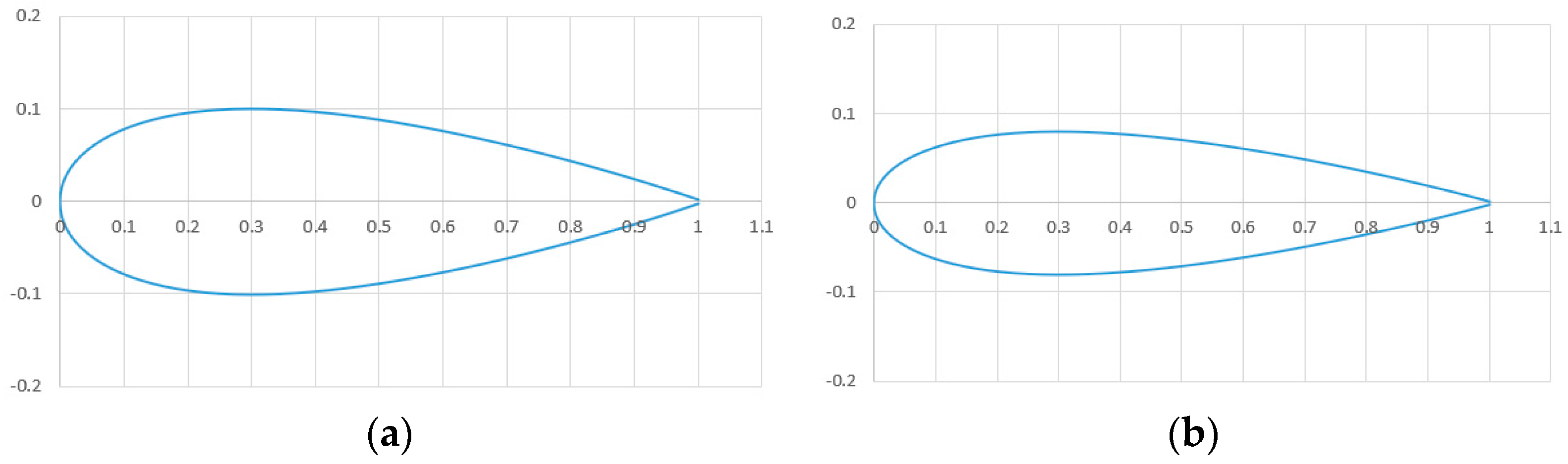
Sailboat sails can be categorized into symmetric and asymmetric cross-sections. Figure 1 compares these two types. Asymmetric airfoils, such as the NACA 4416, typically exhibit a higher lift-to-drag ratio and a greater coefficient of lift compared to symmetric airfoils [11]. Conversely, symmetric airfoils, such as the NACA 0018, produce the same lift under both positive and negative angles of attack. When an unmanned sailboat is sailing in the low Reynolds number interval, symmetric airfoils have the same characteristics on the upper and lower sides, which can provide the same thrust to an unmanned sailboat under the same positive and negative angles of attack and improve the utilization rate of the sail for wind energy [12]. Symmetric airfoils will not suddenly lose thrust and increase resistance when speed occurs, and the change is relatively smooth, which is more conducive to sea sailing.

Figure 1.
Asymmetric and symmetric airfoil sections: (a) NACA 4416 airfoil; (b) NACA 0018 airfoil.
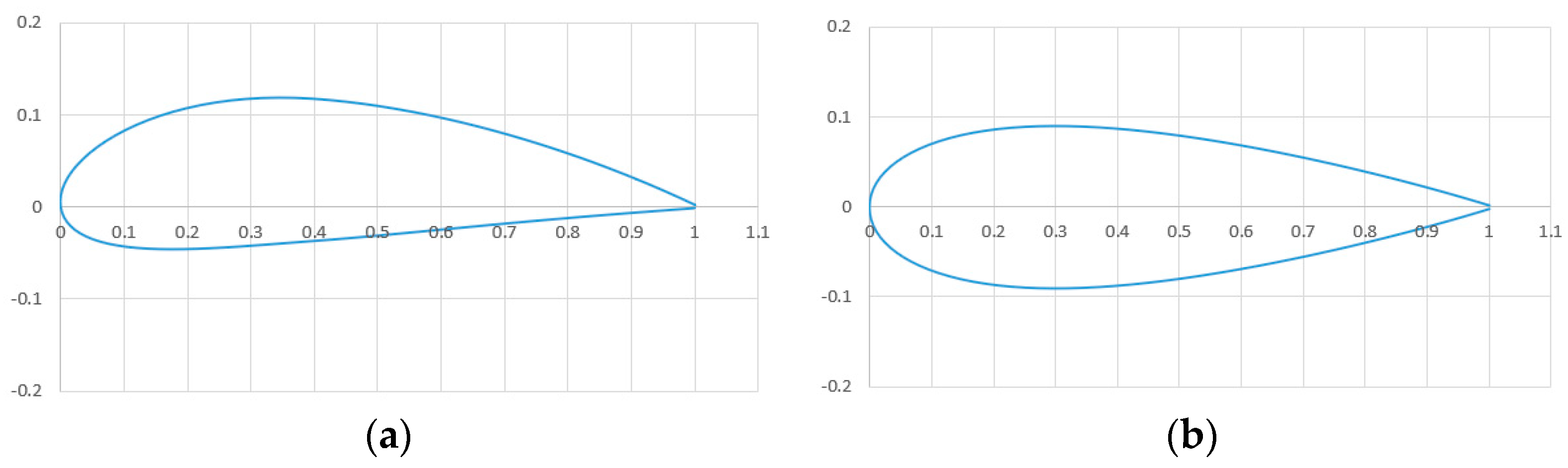
For this study, the symmetrical NACA 0020 airfoil was selected as the mainsail. This airfoil is characterized by a thicker cross-section, a larger stall angle of attack, and a higher drag coefficient [13]. Considering typical sea-level wind speeds range from 6.5 m/s to 11 m/s, the NACA 0020 maintains a substantial lift coefficient even at lower wind speeds, making it ideal for maritime applications. The tail sail, chosen to complement the mainsail, utilizes the symmetrical NACA 0016 airfoil and is scaled to 10% of the mainsail’s size. Figure 2 illustrates the cross-sections of both the mainsail and the tail sail.
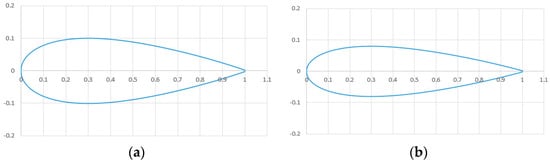
Figure 2.
Mainsail and tail wing sections: (a) NACA 0020 airfoil; (b) NACA 0016 airfoil.
2.2. Parameter Definition
As depicted in Figure 3, the mast is positioned at 1/4 of the mainsail’s chord length. The green marker AP denotes the aerodynamic center of the mainsail. Key parameters include the mainsail chord length (C1), the tip chord (Cn), the root chord (Cm), the mainsail wingspan (B1), the tail chord length (C2), the tail wingspan (B2), the perpendicular distance of the tail from the mast (L), and the height of the tail relative to the mainsail (H). The mainsail aspect ratio AR is calculated as

Figure 3.
Model structure and main parameters.
The taper ratio τ of the wing sail is defined as
2.3. Simulation Model Establishment
Initially, the design parameters are set as follows: the mainsail chord length (C1) is 400 mm, the wingspan (B1) is 1600 mm, the tail chord length (C2) is 120 mm, the wingspan (B2) is 550 mm, the distance between the tail and the aerodynamic center of the mainsail (L) is 600 mm, and the upper and lower position (H) of the tail is 800 mm. The model is constructed in SolidWorks based on these parameters, as shown in Figure 4.
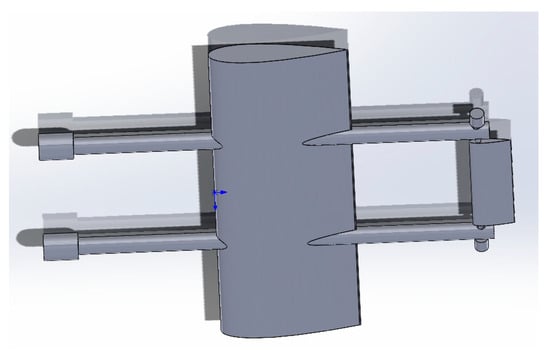
Figure 4.
Simulation model of sail.
3. Aerodynamic Study of Rigid Wing Sails
3.1. Force Analysis of the Wing Sail
Figure 5 provides a simplified top view of the force analysis of the sail system. The mainsail is on the left, and the tail sail is on the right, with AP denoting the aerodynamic center of the mainsail. The environmental wind is represented by V, while the wind generated by the motion of the boat is Vp. The combined effect of these winds produces the relative wind, Vr. The angle between V and Vp is the wind angle, γ. The angle between Vr and the chord of the sail is the angle of attack, α, and the angle between Vp and Vr is the relative wind angle, θ.

Figure 5.
Force analysis of the sail.
Under the influence of Vr, the mainsail generates lift (FL) perpendicular to Vr and drag (FD) parallel to Vr. The combined force F on the mainsail can be decomposed into a thrust force (FT) in the Y direction, which is the desired heading of the sailboat, and a side thrust force (FN) perpendicular to the Y direction. The mainsail also produces a pitching moment (M1), tending to flip it clockwise. To ensure the stability of the sail structure and prevent unnecessary flipping, the moments of the mainsail and tail need to counterbalance each other, making the pitching moment around the mast zero [14]. The tail’s deflection angle, β, is controlled by a motor. The tail sail forms an angle of attack (α−β) with Vr, generating a combined force F2. This force can be decomposed into FB, along the mainsail chord, and FA, perpendicular to it. FA induces a counterclockwise moment (M2) around the mast, counteracting the mainsail’s moment and stabilizing the sail.
The lift coefficient (CL), drag coefficient (CD), thrust coefficient (CT), and side thrust coefficient (CN) are critical for evaluating the aerodynamic performance of the sail [15]. These coefficients are calculated as follows:
where ρ is the air density and represents the projected area of the wing sail.
3.2. Controlling Equations and Turbulence Models
The airflow around the sails of an unmanned sailboat falls within a low Mach number regime [16]. At standard sea level, with an average temperature of about 15 °C (288.15 K), the air around the sails can be considered incompressible. The changes in temperature and density over time in the fluid domain are negligible, allowing the flow to be treated as steady-state. Therefore, the Reynolds-averaged Navier–Stokes (RANS) equations [17] are used for analysis, incorporating the continuity equation and the Navier–Stokes (N-S) equations [18]:
where is the velocity component along the direction and is the velocity component along the direction in the 3D coordinate system, is the fluid density, is the pressure, is the hydrodynamic viscous coefficient, and is the mass force.
Under the actual working condition of the sails in this paper, the flow on the model wall is not only turbulent flow but also the viscous movement between molecules. The SST k-ω model has a mixing function, which makes it more efficient when dealing with deformation near the wall. The SST k-ω turbulence model [19] is adopted due to its high accuracy and faster convergence rate in handling fluid separation flows, making it suitable for this analysis. The transport equations for this model are as follows:
where k is the turbulent kinetic energy, ω represents the specific dissipation rate, Pk denotes the generating term for turbulent kinetic energy k, is the coefficient of molecular viscosity, μt is the coefficient of eddy viscosity, is the fluid density, is fluid velocity, is the equilibrium coefficient between turbulent kinetic energy k and the specific dissipation rate ω, and and are model constants.
3.3. Computational Fluid Domains and Meshing
In fluid dynamics simulations, selecting an appropriate fluid domain size and mesh count is crucial for balancing computational speed and accuracy [20]. The fluid domain must be large enough relative to the wing sails to minimize boundary effects and ensure realistic flow conditions, but not excessively large to avoid reducing computational efficiency. For this study, a rectangular fluid domain is chosen, with dimensions 30 times the mainsail chord length (12,000 mm) in length, 20 times the chord length of the mainsail (8000 mm) in width, and 15 times the mainsail chord length (6000 mm) in height.
The interface between SolidWorks and ANSYS Workbench is configured via CAD Configuration Manager, enabling the import of SolidWorks models into ANSYS Workbench. The boundary conditions for the fluid domain are set as follows (Figure 6a): the left boundary is defined as the velocity inlet with an incoming velocity of 9 m/s, the right boundary as the pressure outlet at one standard atmospheric pressure, the mainsail surface as wall-1, the tail surface as wall-2, and the remaining fluid domain walls as wall-3, wall-4, wall-5, and wall-6. No-slip conditions are applied to the sail surfaces and other wall boundaries [21]. When meshing the fluid domain, the mesh near the sail surface needs to be encrypted because of the numerical simulation of the sail (Figure 6). Tetrahedrons are easier to locally encrypt than hexahedrons, which is particularly important for capturing locations of high stress gradients. Therefore, tetrahedral mesh division is adopted in the calculation domain, the mesh density is increased in the position where the flow field changes, and the mesh in other areas can be as rough as possible, so as to improve the calculation efficiency.

Figure 6.
Boundary condition and grid processing of the simulation model: (a) schematic diagram of the boundary conditions for the model; (b) mesh generation in computational domain; (c) mesh diagram of the cross-section of the wing sail; (d) side view of the mesh diagram for the wing sail.
Mesh independence verification is performed to optimize computational efficiency while maintaining accuracy [22]. The mainsail’s angle of attack is set to 15°, and the flow field wind speed to 9 m/s. The SST k-ω model is used for external flow field simulations. The lift and drag coefficients of the mainsail are calculated for different mesh counts, as shown in Table 1. The analysis indicates that at a mesh count of 8.2 × 10⁵, the drag coefficient stabilizes, and further increasing the mesh count causes minor fluctuations in the lift coefficient, all within a reasonable error range. Thus, for subsequent simulations, the mainsail’s mesh division is fixed at approximately 8.2 × 10⁵.

Table 1.
Mesh independence verification.
4. Simulation Analysis of the Rigid Wing Sail
4.1. Simulation-Related Parameter Settings
The fluid calculations are conducted using Fluent, with the relevant working condition parameters detailed in Table 2. The angle of attack of the mainsail is adjusted by rotating the model. The simulation analyzes the aerodynamic performance of the mainsail based on three factors: the distance between the tail and the mainsail, the spread ratio, and the taper ratio.
Table 2.
Simulation parameter settings.
4.2. Influence of the Distance between the Tail Sail and the Mainsail
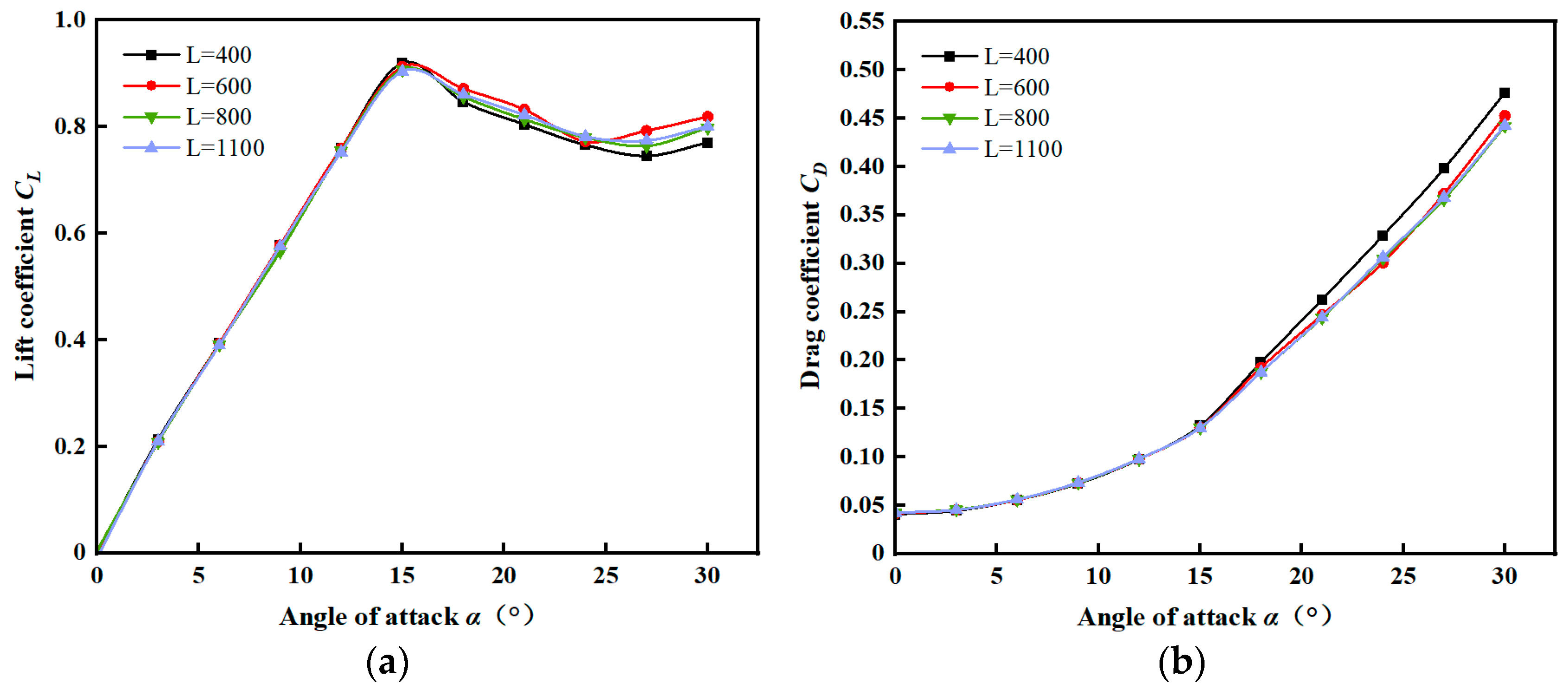
The mainsail is the primary power source for an unmanned sailboat [24]. With an aspect ratio (AR) of 4, a taper ratio (τ) of 1, and a vertical distance (H) of 800 mm between the upper and lower tail positions, other parameters are as specified in Table 2. The vertical distance (L) of the tail sail from the mainsail is varied at 400 mm, 600 mm, 800 mm, and 1100 mm to investigate the aerodynamic properties of the mainsail at different distances. The lift and drag coefficients at different distances, as obtained through Fluent simulations, are shown in Figure 7.
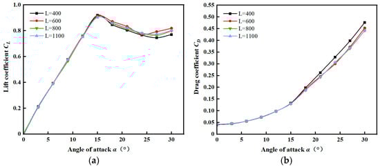
Figure 7.
The relationship between the mainsail lift and drag coefficient with angle of attack: (a) the curves of the lift coefficient against the angle of attack under different distances; (b) the curves of the drag coefficient against the angle of attack under different distances.
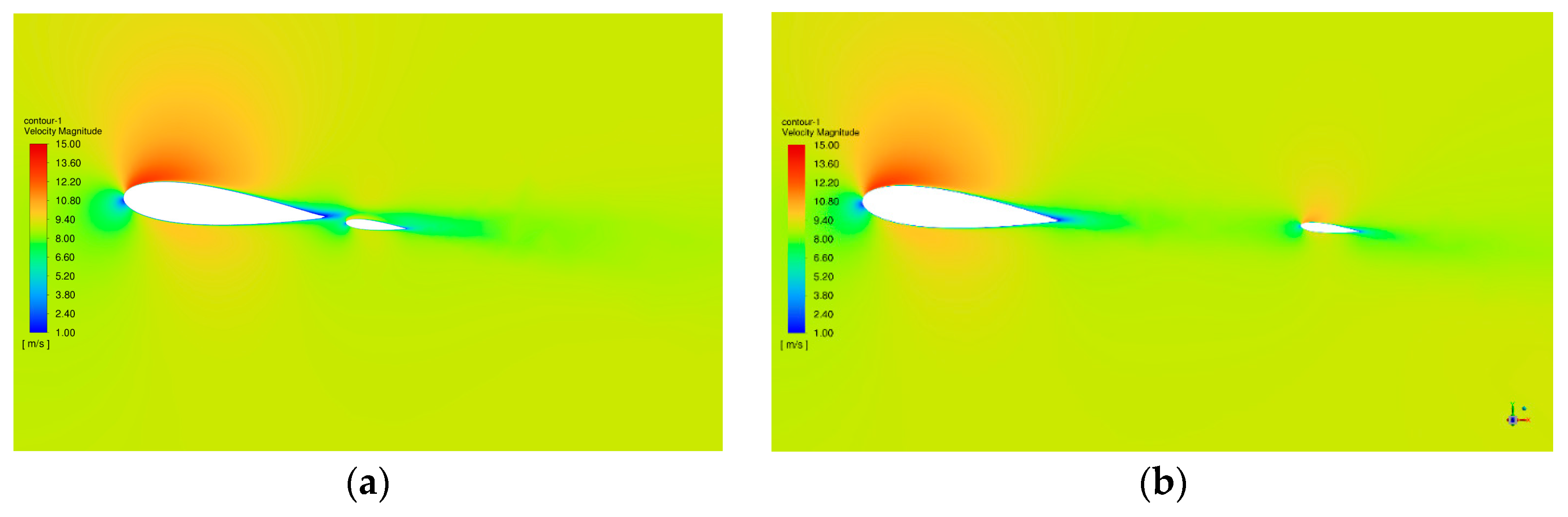
An analysis of Figure 8 indicates that the distance between the tail sail and the mainsail significantly affects the lift and drag coefficients. As seen in Figure 8a, a closer tail impacts the airflow around the mainsail, increasing drag and decreasing lift at certain angles of attack. Conversely, as shown in Figure 8b, when the tail is farther away (L = 800 mm and L = 1100 mm), it has a negligible effect on the mainsail’s airflow. To sum up, in terms of aerodynamic performance, when the tail is close to the mainsail, it has a small impact on the mainsail aerodynamic performance, while when the distance is large, it has no impact on the mainsail. As far as thrust performance is concerned, the left and right position of the tail has no effect on mainsail thrust and side thrust. However, the backward movement of the tail will not only cause the center of gravity of the sail system to shift back, but also increase the rotation radius of the sail, which is not conducive to the control of the sail system. Thus, for optimal balance, the distance (L) between the tail and the mainsail is set at 700 mm, as this avoids unnecessary effects while maintaining control over the sail system [25].

Figure 8.
Distribution of the flow field in the vicinity of the sail: (a) velocity clouds when the tail is closer to the mainsail; (b)velocity clouds when the tail is farther away from the mainsail.
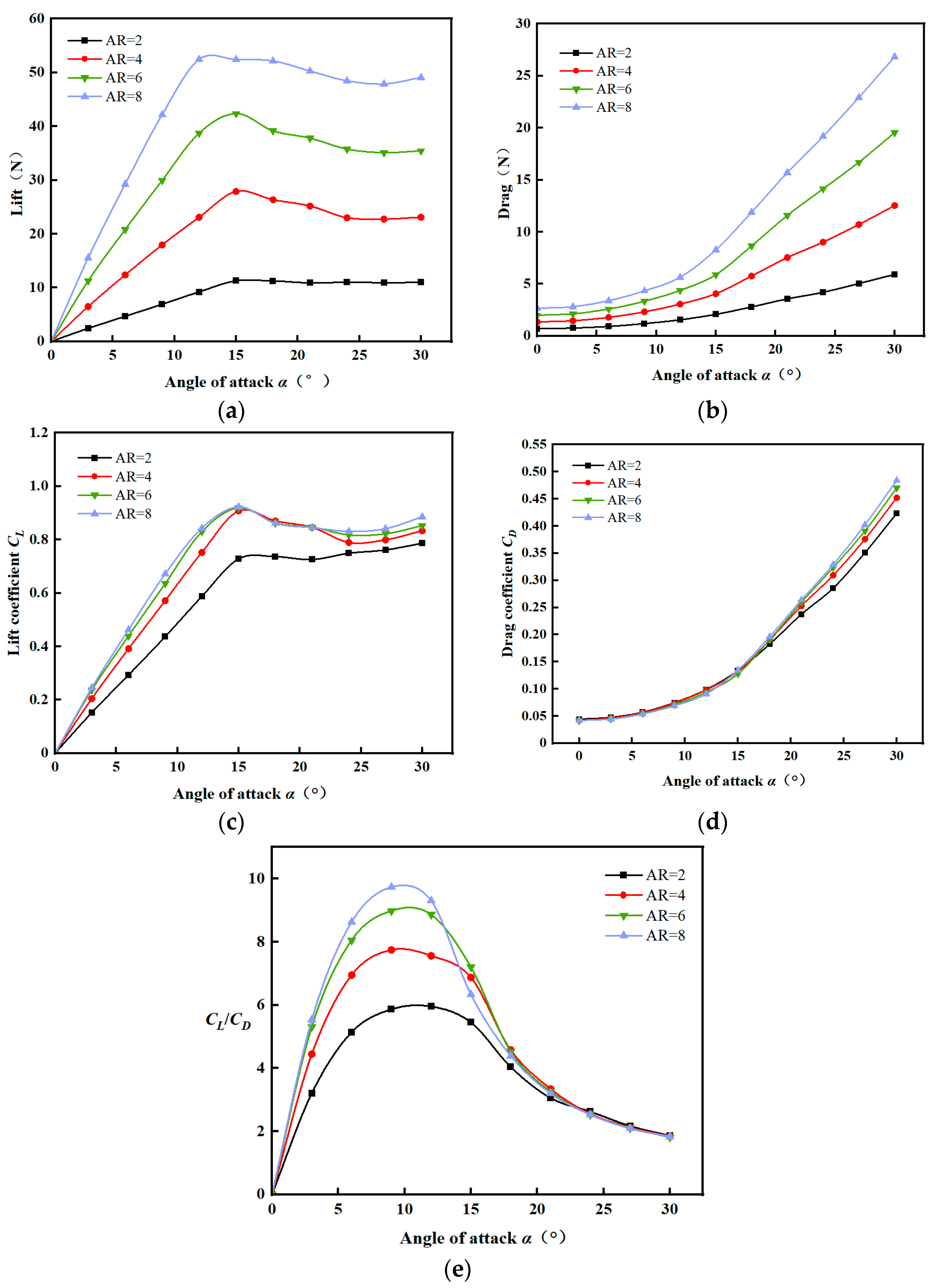
4.3. Effect of Spread Ratio on Mainsail Aerodynamics
With the tail positioned (L) 700 mm vertically from the mainsail and 800 mm between the upper and lower tail positions (H), the taper ratio (τ) remains at 1, while the mainsail aspect ratio (AR) is varied at 2, 4, 6, and 8. Other parameters are shown in Table 2. The influence of the aspect ratio on the aerodynamics of the mainsail is investigated. The Fluent simulations reveal the changes in lift, drag, lift coefficient, drag coefficient, and lift–drag ratio under different aspect ratios, as shown in Figure 9. From the analysis, it is evident that a higher aspect ratio increases both the lift and drag of the wing sail, especially at the same angle of attack. For angles of attack less than 15°, the lift coefficients have a linear relationship with the angle of attack, increasing with higher angles. Beyond 15°, the lift coefficients decrease due to stalling and local separation on the leeward side of the sail. The drag coefficient of the wing sail also increases with the angle of attack, with higher aspect ratios leading to greater drag.

Figure 9.
Lift and drag characteristic curves with different aspect ratios: (a) lift; (b) drag; (c) lift coefficient; (d) drag coefficient; (e) lift–drag ratio.
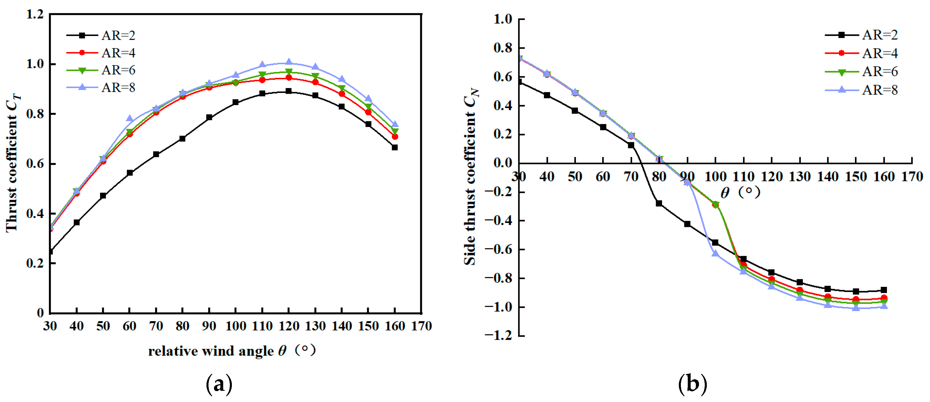
Thrust is the primary driving force for unmanned sailboats. Figure 10 shows the maximum thrust coefficient and corresponding side thrust coefficient for relative wind angles (θ) from 30° to 160°. The analysis shows that larger aspect ratios yield higher thrust coefficients. When the relative wind angle θ is less than 30°, the thrust coefficient of the sail is minimal, and the side thrust coefficient is relatively large, unfavorable for sailing. In the range of 30° to 120°, as the relative wind angle θ increases, the thrust coefficient increases, and the side thrust decreases, favorable for sailing. At θ = 120°, the thrust coefficient peaks, due to the maximum combined lift and drag forces in the thrust direction. Beyond 120°, the thrust coefficient declines as θ increases. In the interval from 120° to 160°, the thrust coefficient decreases as the relative wind angle θ increases. The coefficient of lateral thrust shows a decreasing trend in the range of θ from 30° to 160° and decreases to a negative number around 75° to 80°; that is, the direction of lateral thrust changes. To sum up, it is necessary to consider the appropriate aspect ratio when designing the mainsail, and a higher aspect ratio can improve the lift coefficient and thrust coefficient of the sail so that it has a higher conversion efficiency. However, too high of a aspect ratio will make the sail elongated, resulting in greater bending stress, which is not conducive to the stability of the mainsail structure. To balance structural integrity and aerodynamic performance, the mainsail aspect ratio (AR) is set to 5.
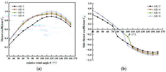
Figure 10.
Thrust coefficient curve and side thrust coefficient curve: (a) thrust coefficient; (b) side thrust coefficient.
4.4. Effect of Taper Ratio on Mainsail Aerodynamics
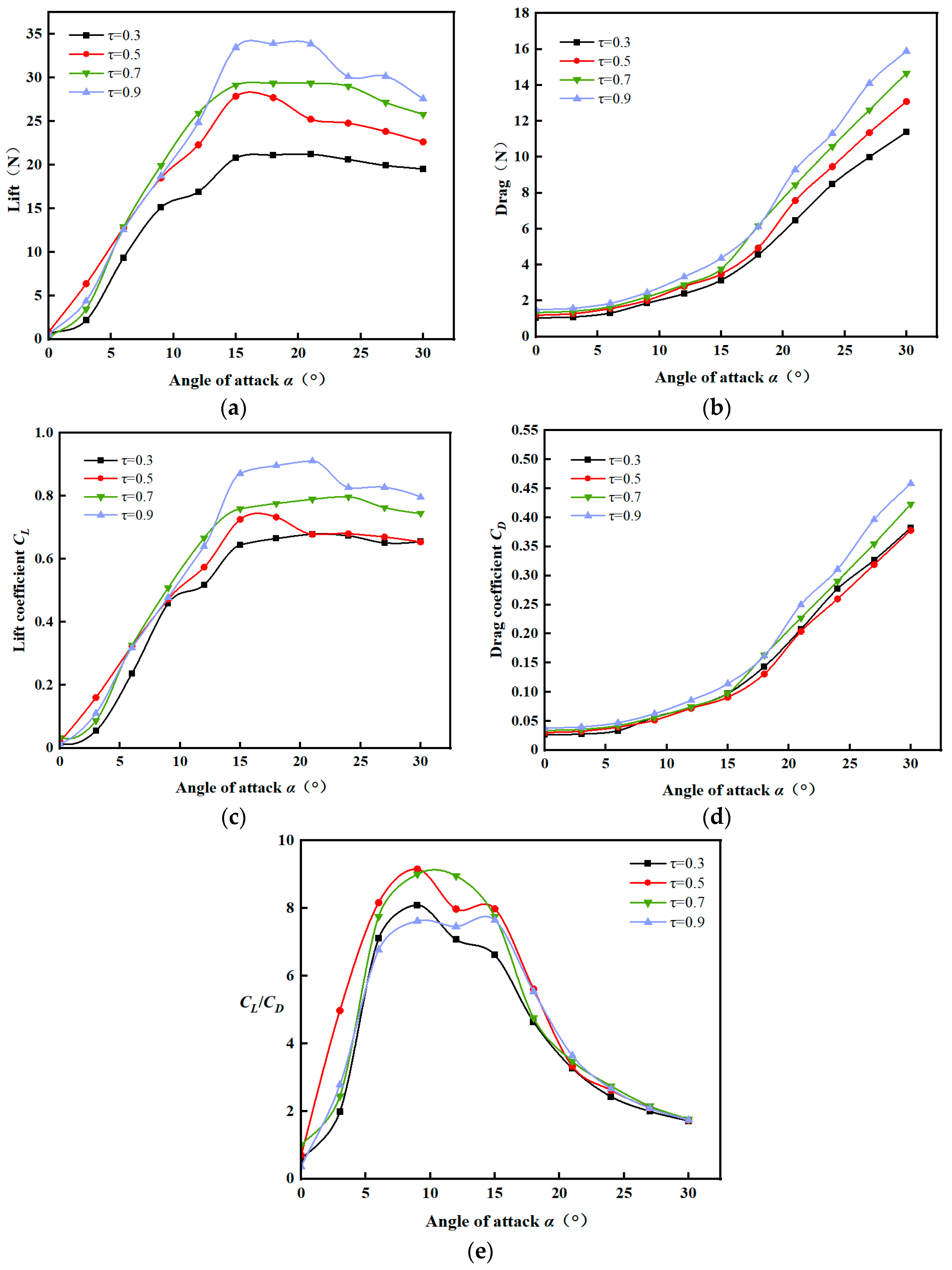
With a vertical distance (L) of 700 mm from the mast, upper and lower tail positions (H) at 800 mm, and a mainsail aspect ratio (AR) of 5, taper ratios (τ) of 0.3, 0.5, 0.7, and 0.9 are examined. Other parameters are depicted in Table 2. The Fluent simulations analyze the aerodynamic performance under different taper ratios, revealing the changes in lift, drag, lift coefficient, drag coefficient, and lift–drag ratio, as shown in Figure 11. The analysis indicates that the taper ratio affects the mainsail’s aerodynamics by improving the distribution of lift force. A higher taper ratio results in more lift generated near the root, reducing the stress at the root of the wing sail. At τ = 0.9, the sail achieves the highest peak lift coefficient. Observing the lift–drag ratio curve, the characteristics are optimal at τ = 0.7, providing a smoother curve and better aerodynamic performance. The tapered sail surface also lowers the center of gravity and reduces the root bending load. Thus, a taper ratio (τ) of 0.7 is selected for the conical wing sail.
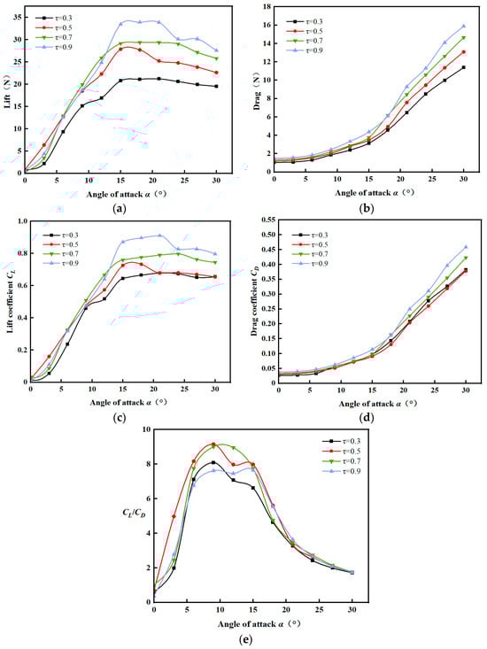
Figure 11.
Lift resistance characteristic curves at different taper ratios: (a) lift; (b) drag; (c) lift coefficient; (d) drag coefficient; (e) lift–drag ratio.
4.5. Mainsail Structure Optimization
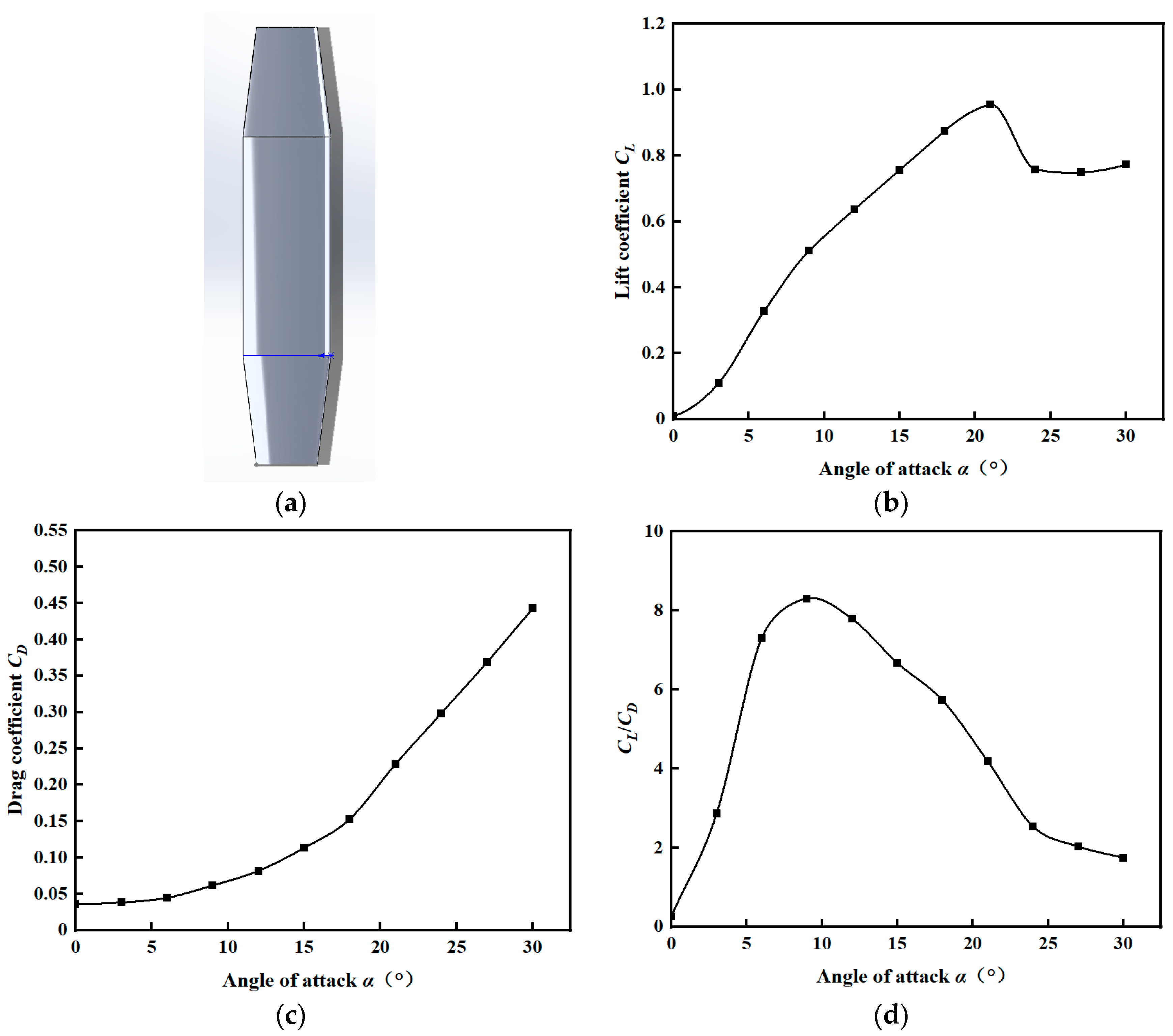
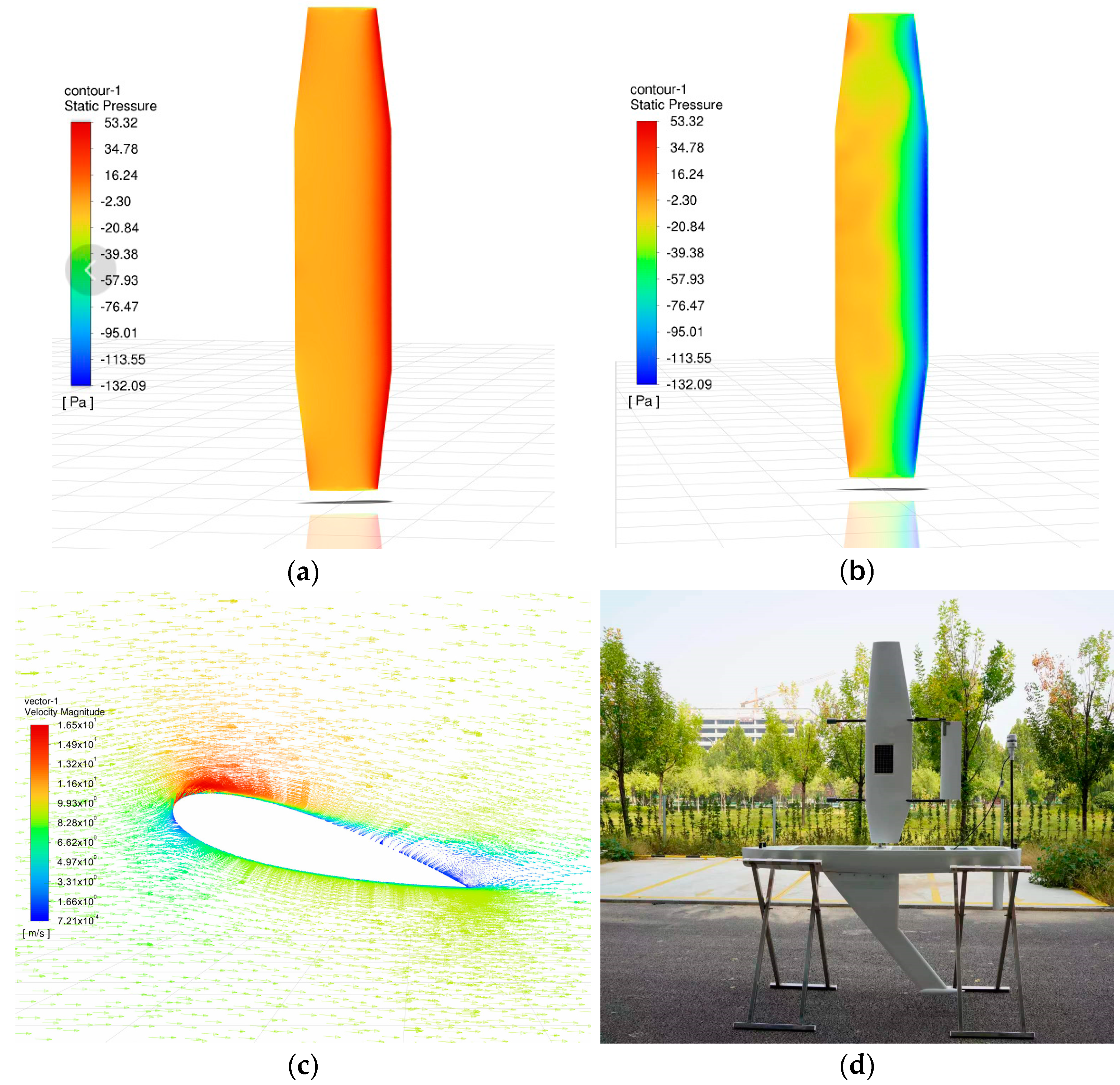
Based on the optimization of the design parameters, the mainsail aspect ratio is set to AR = 5 and the taper ratio to τ = 0.7. The mainsail is re-modeled accordingly, as shown in Figure 12a. The optimized model is then imported into Fluent for numerical simulation with a flow field wind speed of 9 m/s, and other parameters are shown in Table 2. The aerodynamic performance of the optimized mainsail is analyzed for angles of attack from 0° to 30°, as shown in Figure 12. The lift coefficient peaks at 0.96 at an angle of attack (α) of 21° (Figure 12b), and the drag coefficient is lower compared to conventional sails (Figure 12c). The lift–drag curve is smooth, with a ratio reaching 8.4 at an angle of attack (α) of 9°, as shown in Figure 12d. The surface pressure distribution of the windward side and leeward side for the mainsail is depicted in Figure 13a,b. The velocity vector diagram of the mainsail cross-section at an angle of attack of 15° is shown in Figure 13c. Finally, based on the results of the simulation experiments, the mainsail structure is optimized to improve the sail performance, and the physical object is processed according to the above model, as shown in Figure 13d.
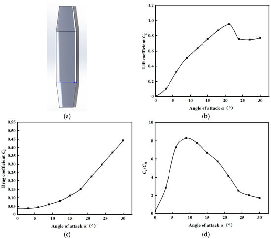
Figure 12.
Optimized mainsail and its lift–drag characteristic curve: (a) optimized mainsail; (b) lift coefficient curve of the optimized model; (c) drag coefficient curve of the optimized model; (d) lift–drag ratio curve of the optimized model.

Figure 13.
Cloud image near the mainsail and the actual sailboat: (a) pressure cloud image of the windward side of the mainsail; (b) pressure cloud image of the leeward side of the mainsail; (c) vector drawing of speed near the mainsail; (d) image of the developed unmanned sailboat.
Banks, J et al. conducted wind tunnel experiments on the proposed thin film sail [26]. The design proposed in this paper can provide higher thrust efficiency for sailboats at the same wind speed and angle of attack. A comparison is shown in Table 3:
Table 3.
Lift and drag performance comparison.
5. Conclusions
This paper focuses on the selection, design, modeling, aerodynamic simulation analysis, and optimization of sails for unmanned sailing ships. Firstly, a comparative analysis of flexible and rigid sails reveals that rigid sails offer superior aerodynamic performance. Additionally, by comparing asymmetric and symmetric wing types, it is determined that the symmetric wing type is preferable for unmanned sailing boats due to its ability to accept winds from both the left and right and its structural suitability. Secondly, a rigid wing sail is modeled, and its aerodynamic properties are studied using CFD technology. This study examines the effects of different aspect ratios, taper ratios, and tail positions on the aerodynamic performance of the mainsail. The distance (L) between the tail and the mainsail is set at 700 mm, the mainsail aspect ratio (AR) is set to 5, and the taper ratio (τ) is set to 0.7, leading to the selection of optimal design parameters. Finally, based on the simulation results, the mainsail structure is optimized to enhance sail performance, and the optimized sail is successfully fabricated. Modeling and aerodynamic analyses of wind sails can effectively predict their performance under specific operating conditions. Through simulation, shortcomings in the design can be identified, reducing costs in the early stages of design. The proposed sail structure is more suitable for small, unmanned sailboats. Compared with previous studies, this structure has better aerodynamic performance. The research presented in this paper provides valuable data to support the optimization of sail thrust and control strategies for unmanned sailing ships, offering promising applications in marine engineering. Further research on the sail control system of unmanned sailboats can be carried out, and several real ship tests can be carried out to verify the accuracy of the simulation analysis.
Author Contributions
Conceptualization, S.F. and C.T.; methodology, S.F. and C.T.; software, S.F.; validation, S.F., Y.Z. and T.D.; formal analysis, Y.Z.; investigation, C.X.; resources, T.X.; data curation, S.F.; writing—original draft preparation, S.F.; writing—review and editing, S.F.; visualization, T.D.; supervision, C.T.; project administration, H.W.; funding acquisition, C.T. All authors have read and agreed to the published version of the manuscript.
Funding
This research was funded by the Shandong Province science and technology SMES innovation ability improvement project of China (Grant No. 2023TSGC0350).
Data Availability Statement
All data generated during this study are included in this published article.
Conflicts of Interest
The authors declare no conflicts of interest.
References
- Agarwala, N. Monitoring the ocean environment using robotic systems: Advancements, trends, and challenges. Mar. Technol. Soc. J. 2020, 54, 42–60. [Google Scholar] [CrossRef]
- Kabanov, A.; Kramar, V. Marine internet of things platforms for interoperability of marine robotic agents: An overview of concepts and architectures. J. Mar. Sci. Eng. 2022, 10, 1279. [Google Scholar] [CrossRef]
- Douglas, S.B.; Conway, N.R.; Weklar, M.B. The Design, Building and Testing of a Trans-Atlantic Autonomous Sailboat. In SNAME Maritime Convention; SNAME: Providence, RI, USA, 2015; p. D031S009R014. [Google Scholar] [CrossRef]
- Elkaim, G.H. System Identification for Precision Control of a Wingsailed GPS-Guided Catamaran. Ph.D. Thesis, Stanford University, Stanford, CA, USA, 2002. [Google Scholar]
- Sadaq, S.I.; Mehdi, S.N.; Mehdi, S.D.; Yasear, S. Analysis of NACA 0020 aerofoil profile rotor blade using CFD approach. Mater. Today Proc. 2022, 64, 147–160. [Google Scholar] [CrossRef]
- Mayerfeld, P. Fluorometers: Integration experiences with unmanned vehicles. In Proceedings of the OCEANS 2017-Anchorage, Anchorage, AK, USA, 18–21 September 2017; pp. 1–5. [Google Scholar]
- Li, D.Q.; Zheng, X.; Li, J.; Dai, J.J.; Li, G.H. A collapsible twin-tailed wing sail device. J. Jiangsu Univ. Sci. Technol. 2017, 31, 707–713. (In Chinese) [Google Scholar]
- Qin, G.F.; Li, X.; Liu, R.L.; Dong, L.J. Research on Sail Control Strategy of Unmanned Sailing Vessel Based on CFD Technology. Technol. Innov. Appl. 2018, 33, 8–14. (In Chinese) [Google Scholar]
- Friebe, A.; Ferreira, P.; Guedes, P.; Malheiro, B.; Silva, M.S.; Waller, M. Rigid wing sailboats: A state of the art survey. Ocean. Eng 2019, 187, 106150. [Google Scholar] [CrossRef]
- Atkinson, G. Aerodynamic Analysis of Segment Rigid Sails and Estimation of Propulsive Power from Sail Array on Large Powered Ship. Master’s Thesis, University of Tasmania, Launceston, TAS, Australia, 2020. [Google Scholar]
- Katz, J. Lift and Drag Measurements of Tandem, Symmetric Airfoils. In Proceedings of the 31st AIAA Applied Aerodynamics Conference, San Diego, CA, USA, 24–27 June 2013; p. 2659. [Google Scholar] [CrossRef]
- Santos, D.; Junior, A.G.S.; Negreiros, A.; Vilas Boas, J.; Alvarez, J.; Araujo, A.; Aroca, R.V.; Gonçalves, L.M. Design and implementation of a control system for a sailboat robot. Robotics 2016, 5, 5. [Google Scholar] [CrossRef]
- Kemalı, H.; Saydam, A.Z.; Helvacıoğlu, Ş. Investigation of the Effect of Leading-Edge Tubercles on Wingsail Performance. J. EMS 2020, 8, 54–65. [Google Scholar] [CrossRef]
- Fossati, F.; Muggiasca, S. Experimental investigation of sail aerodynamic behavior in dynamic conditions. J. Sailboat. Technol. 2011, 2, 1–41. [Google Scholar]
- Sun, Z.; Hu, F.; Yu, J.; Zhao, W.; Zhang, A. Influence of autonomous sailboat dual-wing sail interaction on lift coefficients. J. Ocean. Univ. China 2022, 21, 656–668. [Google Scholar] [CrossRef]
- Li, C.; Wang, H.; Sun, P. Study on the Influence of Gradient Wind on the Aerodynamic Characteristics of a Two-Element Wingsail for Ship-Assisted Propulsion. J. Mar. Sci. Eng. 2023, 11, 134. [Google Scholar] [CrossRef]
- Alfonsi, G. Reynolds-averaged Navier–Stokes equations for turbulence modeling. Appl. Mech. Rev. 2009, 62, 040802. [Google Scholar] [CrossRef]
- He, X.; Luo, L.-S. Lattice Boltzmann model for the incompressible Navier–Stokes equation. J. Stat. Phys. 1997, 88, 927–944. [Google Scholar] [CrossRef]
- Moshfeghi, M.; Song, Y.J.; Xie, Y.H. Effects of near-wall grid spacing on SST-K-ω model using NREL Phase VI horizontal axis wind turbine. J. Wind. Eng. Ind. Aerodyn. 2012, 107, 94–105. [Google Scholar] [CrossRef]
- Tu, J.; Yeoh, G.H.; Liu, C.; Tao, Y. Computational Fluid Dynamics: A Practical Approach, 4th ed.; Elsevier: Gambrigde, MA, USA, 2023. [Google Scholar]
- Zorrilla, R.; Larese, A.; Rossi, R. A modified finite element formulation for the imposition of the slip boundary condition over embedded volumeless geometries. Comput. Method. Appl. Mech. Eng. 2019, 353, 123–157. [Google Scholar] [CrossRef]
- Seeni, A.; Rajendran, P.; Mamat, H. A CFD mesh independent solution technique for low Reynolds number propeller. CFD Lett. 2019, 11, 15–30. [Google Scholar]
- Xiao, H.; Wang, J.; Liu, Z.; Liu, W. A consistent SIMPLE algorithm with extra explicit prediction—SIMPLEPC. Int. J. Heat Mass Transf. 2018, 120, 1255–1265. [Google Scholar] [CrossRef]
- An, Y.; Yu, J.; Zhang, J. Autonomous sailboat design: A review from the performance perspective. Ocean. Eng. 2021, 238, 109753. [Google Scholar] [CrossRef]
- Lappas, V.; Mengali, G.; Quarta, A.A.; Gil-Fernandez, J.; Schmidt, T.; Wie, B. Practical systems design for an earth-magnetotail-monitoring solar sail mission. J. Spacecr. Rocket. 2009, 46, 381–393. [Google Scholar] [CrossRef]
- Banks, J.; Cocard, M.; Jaspe, J. Assessing the impact of membrane deformations on wing sail performance. J. Sail. Technol. 2021, 6, 73–90. [Google Scholar] [CrossRef]
Disclaimer/Publisher’s Note: The statements, opinions and data contained in all publications are solely those of the individual author(s) and contributor(s) and not of MDPI and/or the editor(s). MDPI and/or the editor(s) disclaim responsibility for any injury to people or property resulting from any ideas, methods, instructions or products referred to in the content. |
© 2024 by the authors. Licensee MDPI, Basel, Switzerland. This article is an open access article distributed under the terms and conditions of the Creative Commons Attribution (CC BY) license (https://creativecommons.org/licenses/by/4.0/).