

Review of Fault-Tolerant Control Methods for Suspension Systems: From Road Vehicles to Maglev Trains


Abstract
1. Introduction
- This paper will emphasize the magnetic levitation train suspension system (MLTS) and incorporate it with the vehicle semi-active/active suspension system, which shares a similar structure with the MLTS. The study examines, evaluates, and synthesizes past research on fault-tolerant control, focusing on the routes, theoretical approaches, and technological tools that are common to both systems. The intended audience includes scholars and engineers in the fields of rail transportation, fault-tolerant control, and magnetic levitation.
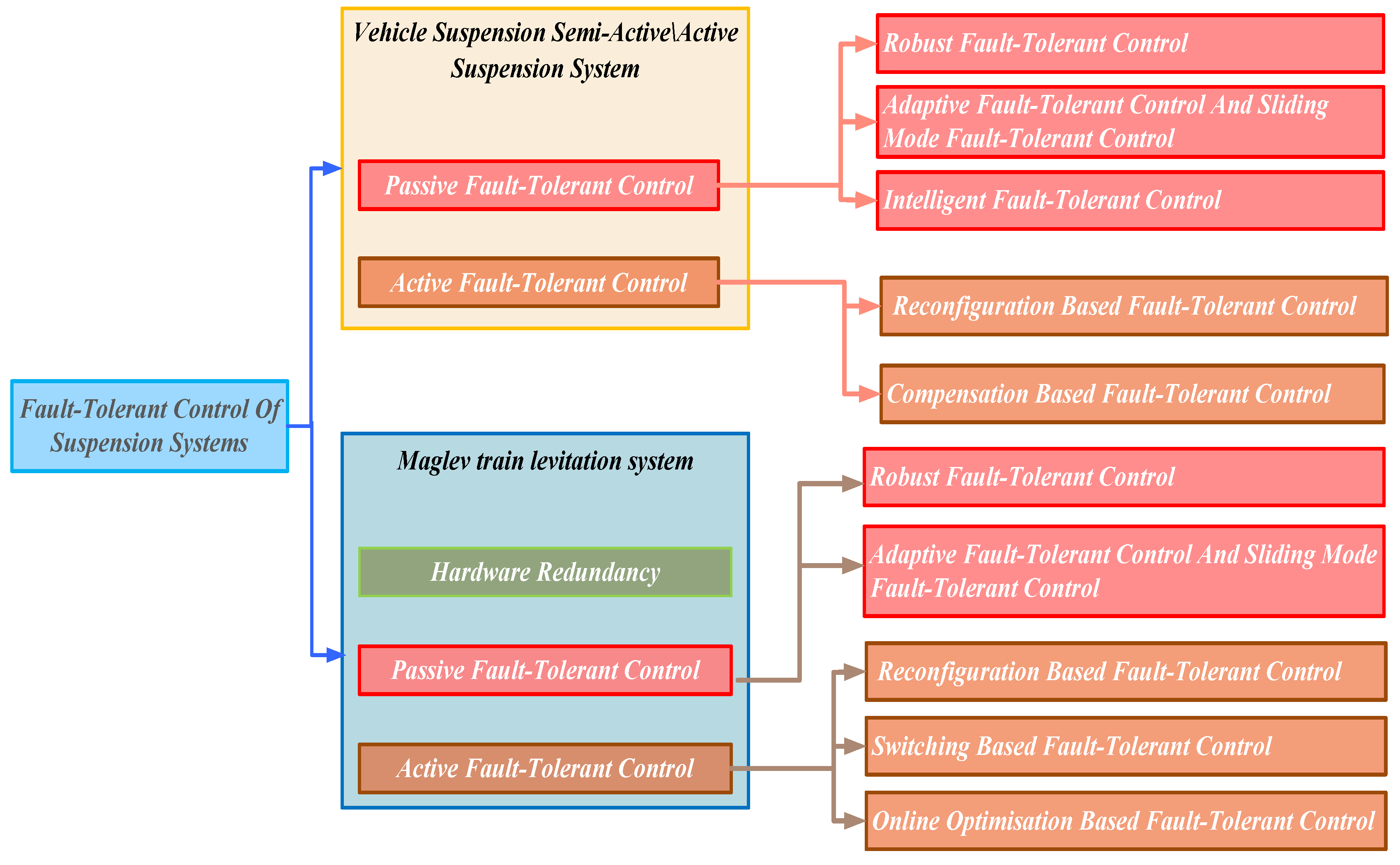
- The analysis examines the features of two types of engineered systems designed for fault-tolerant control. It delves into specific aspects such as redundancy, fault detection, fault diagnosis, and fault-tolerant control. This information can guide the selection of fault-tolerant strategies in different failure scenarios and holds significant implications for engineering applications. The fault-tolerant control methods discussed in this paper for suspension systems can be basically classified according to Figure 6.
2. Technical Characteristics of Suspension Systems
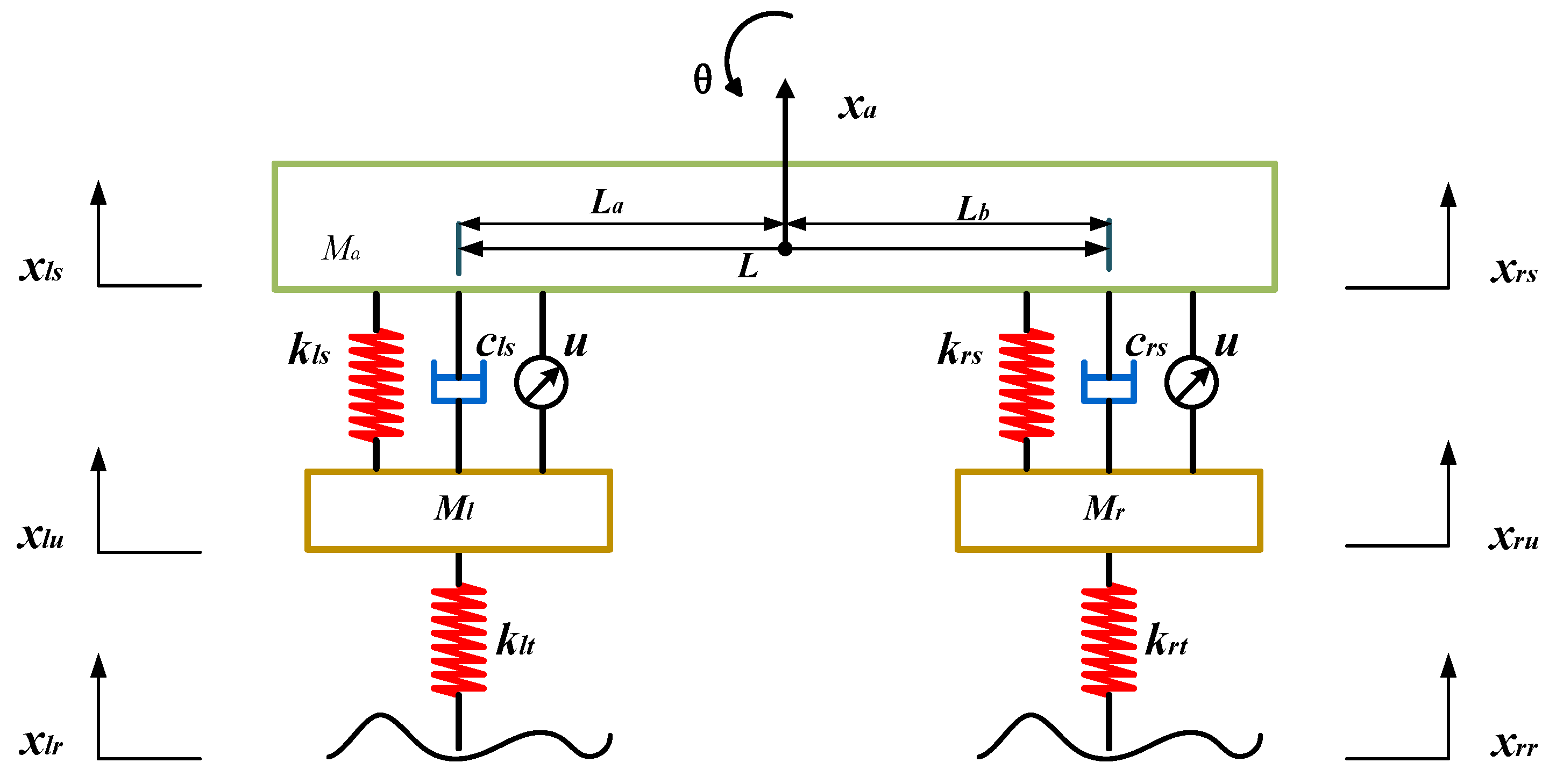
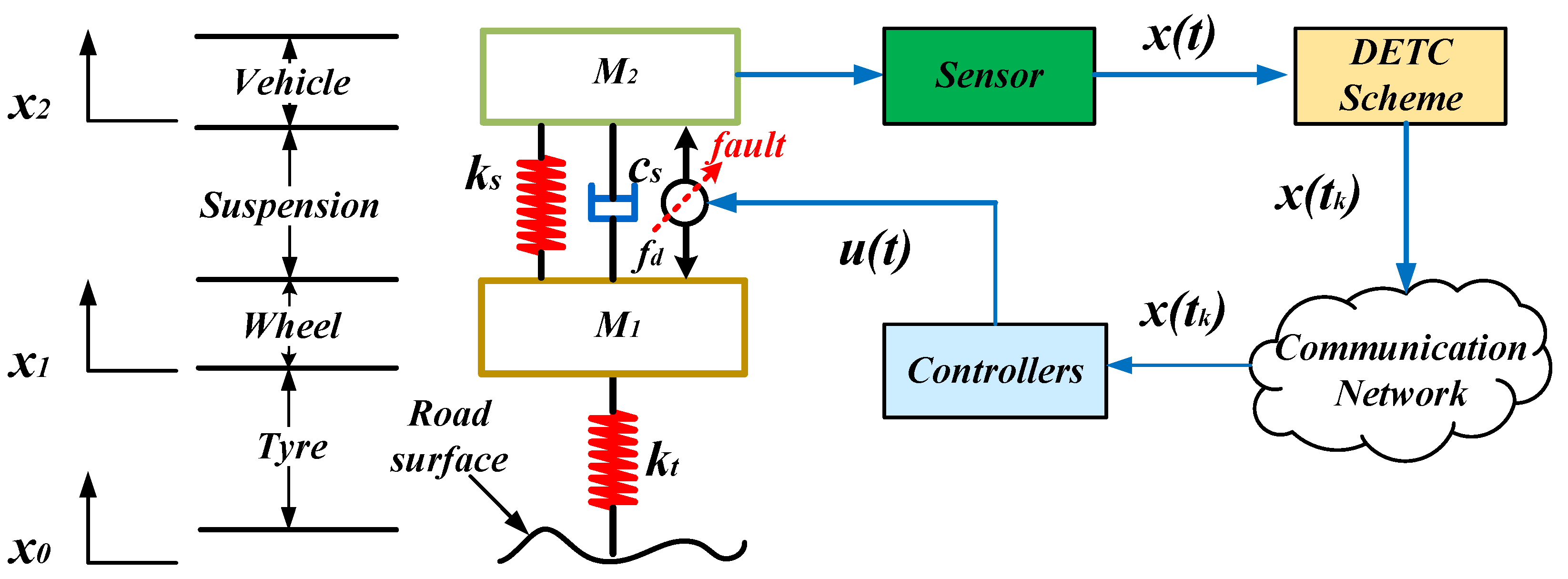
2.1. Dynamic Modeling of Road Vehicle Suspension Systems
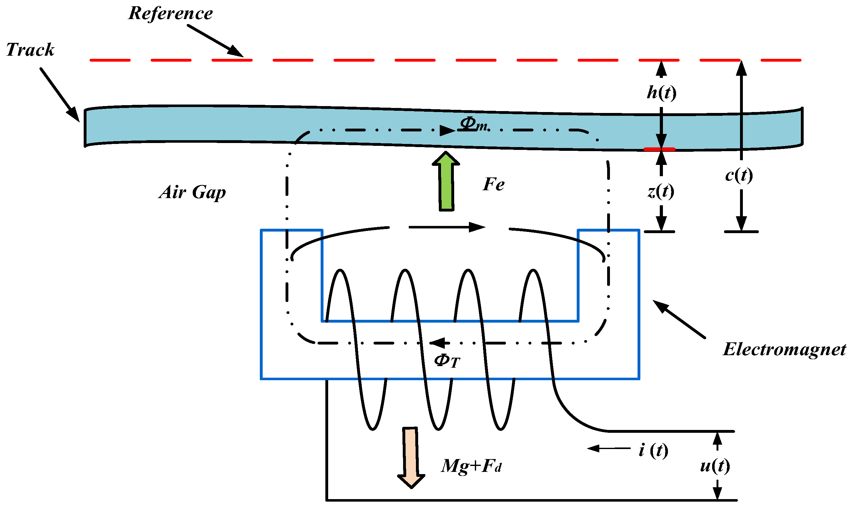
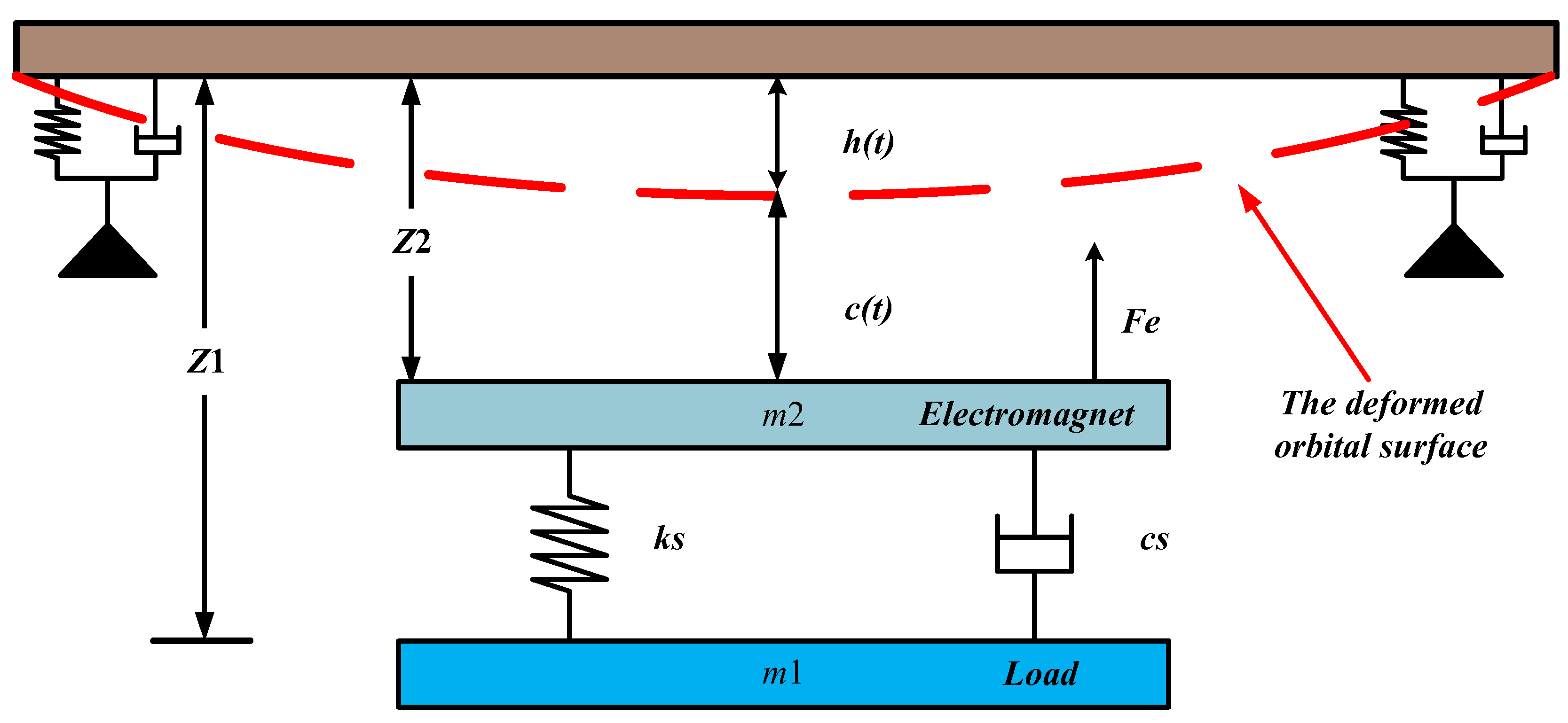
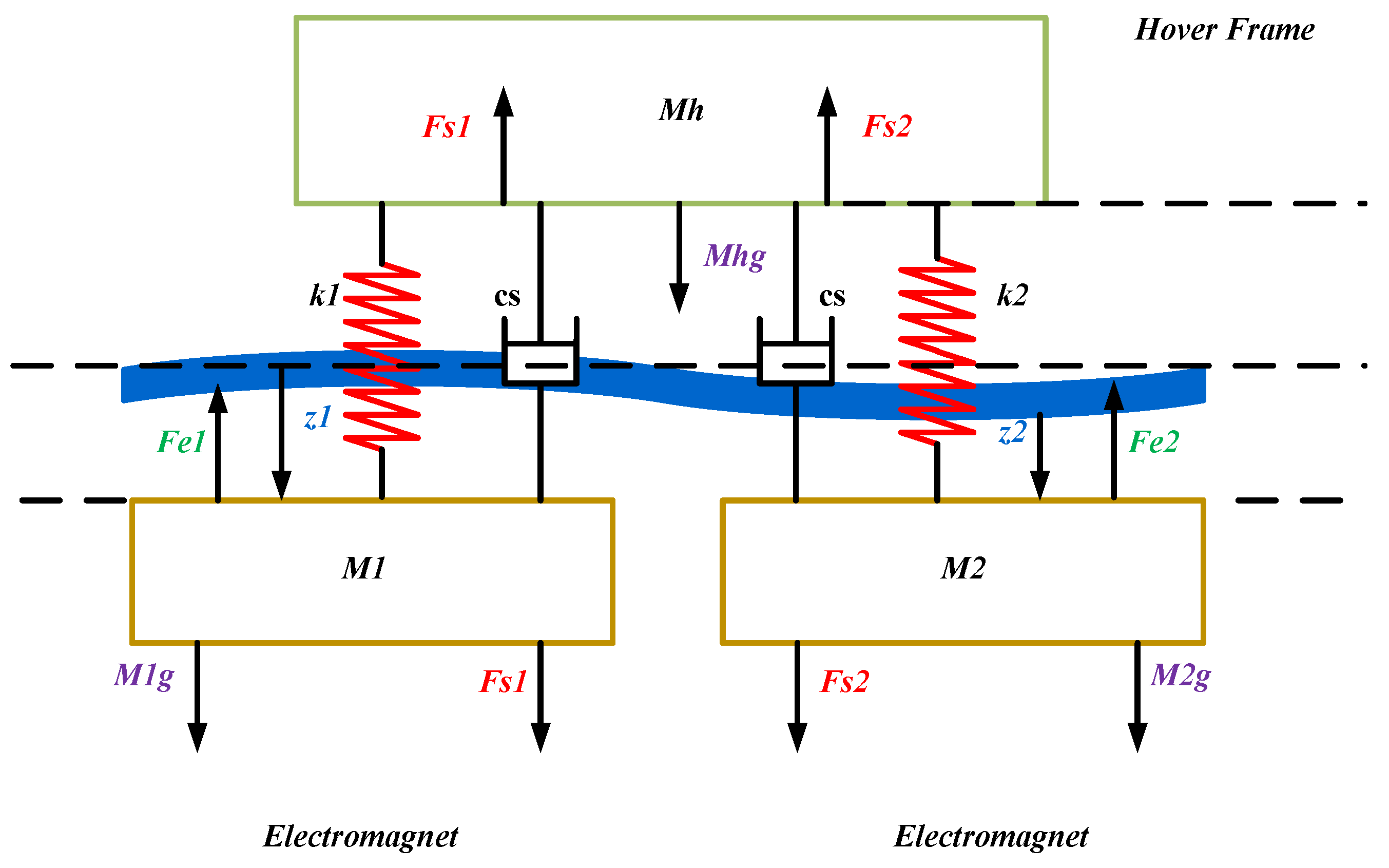
2.2. Dynamic Modeling of the Suspension System of a Magnetic Levitation Train
3. Fault-Tolerant Control of Road Vehicle Active Suspension Systems
3.1. Passive Fault-Tolerant Control Method
3.1.1. Robust Fault-Tolerant Control Method
3.1.2. Adaptive Fault-Tolerant Control and Sliding Mode Fault-Tolerant Control Methods
3.1.3. Intelligent Fault-Tolerant Control Method
3.2. Active Fault-Tolerant Control Method
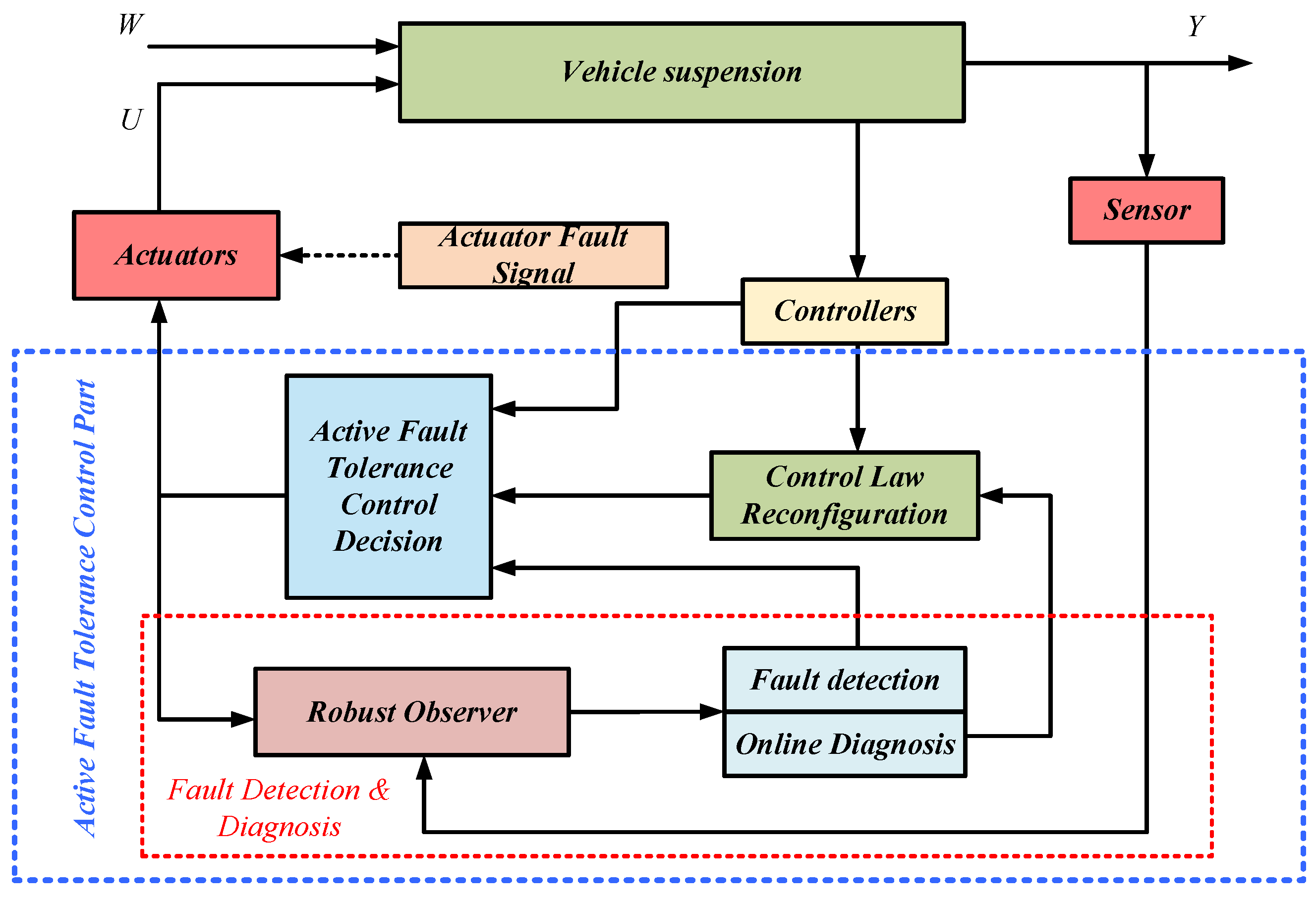
3.2.1. Fault Tolerance Control Method Based on Reconfiguration
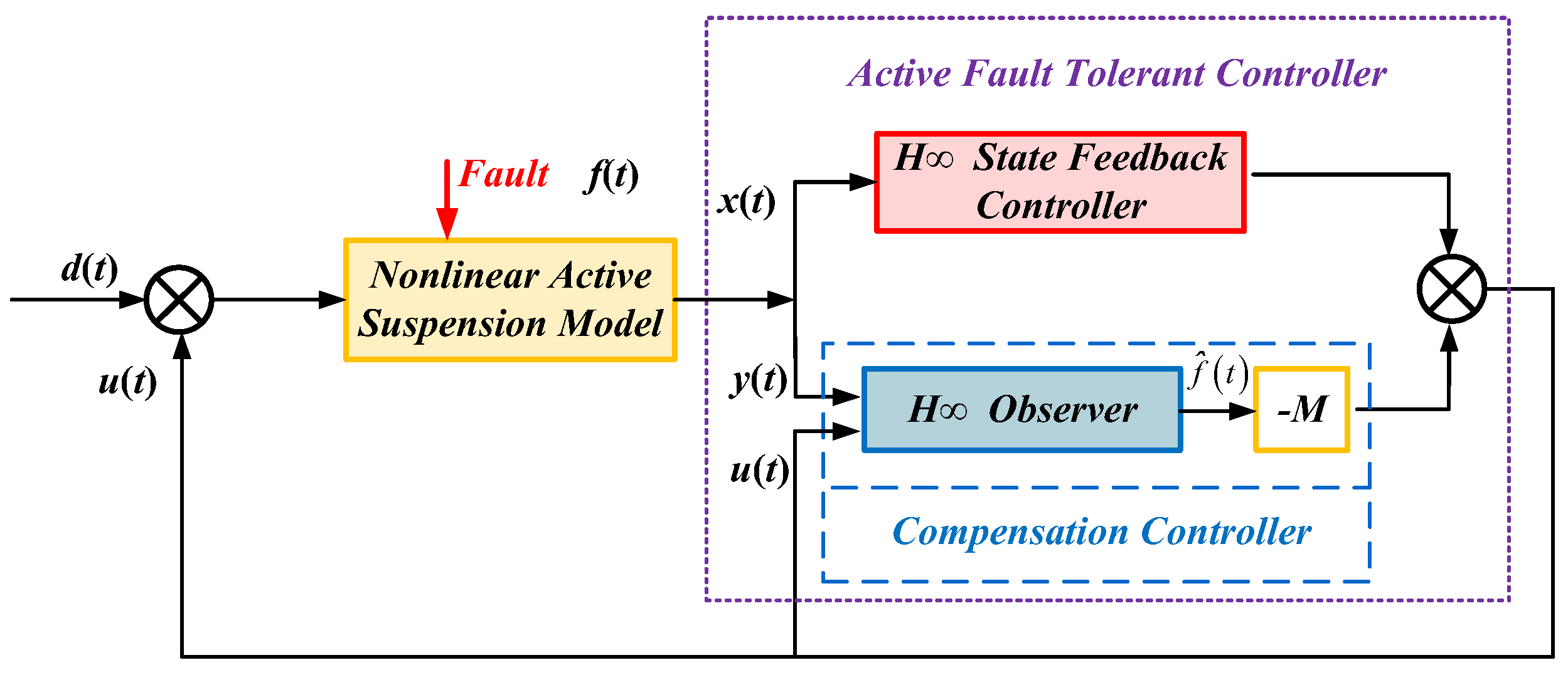
3.2.2. Fault-Tolerant Control Method Based on Compensation
4. Fault-Tolerant Control for Maglev Train Suspension Systems
4.1. Hardware Redundancy Strategy
4.2. Passive Fault-Tolerant Control Method
4.2.1. Robust Passive Fault-Tolerant Control Method
4.2.2. Adaptive Fault-Tolerant Control Method
4.3. Active Fault-Tolerant Control Method
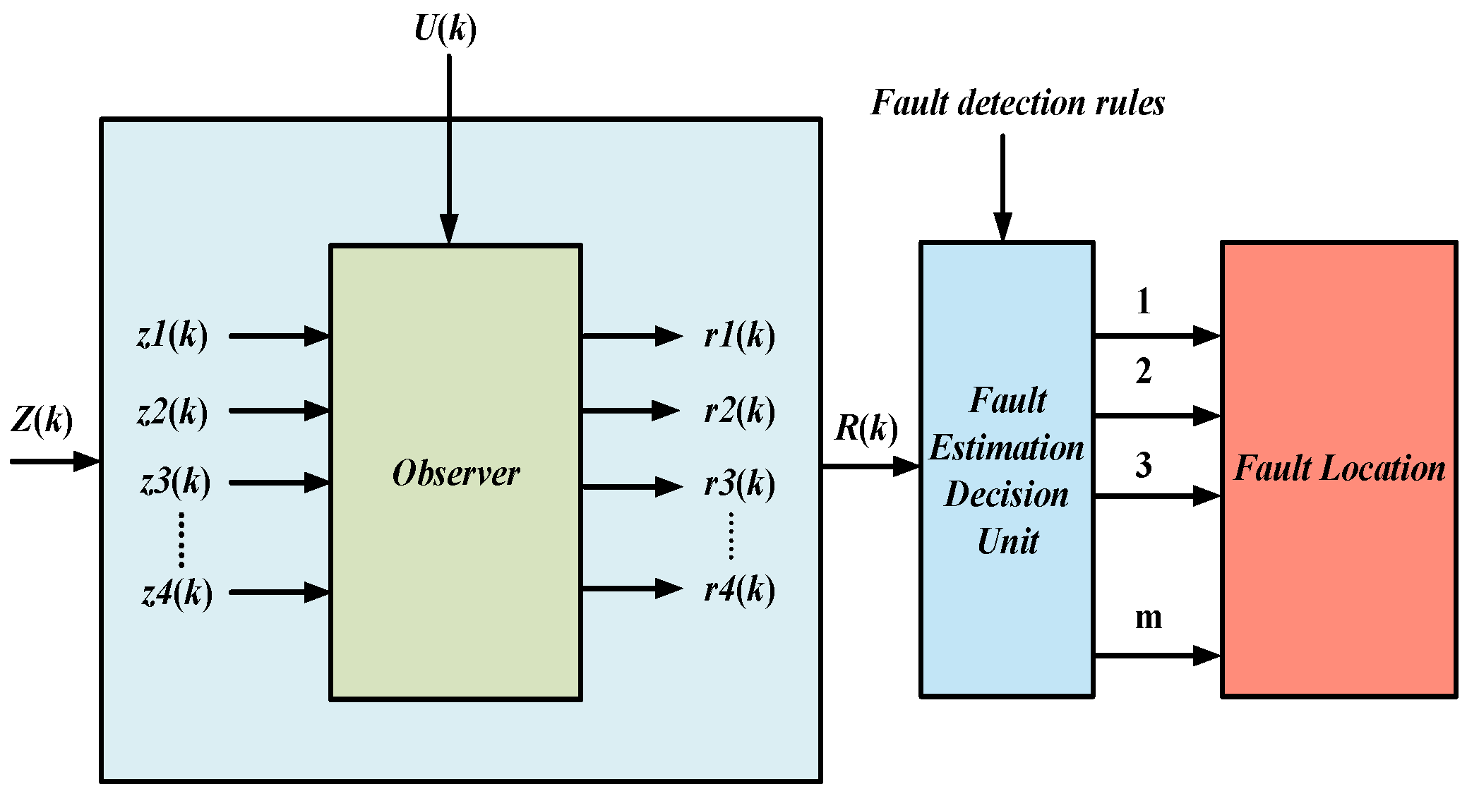
4.3.1. Fault Detection and Diagnosis
- Fault detection
- Fault diagnosis
4.3.2. Active Fault-Tolerant Control
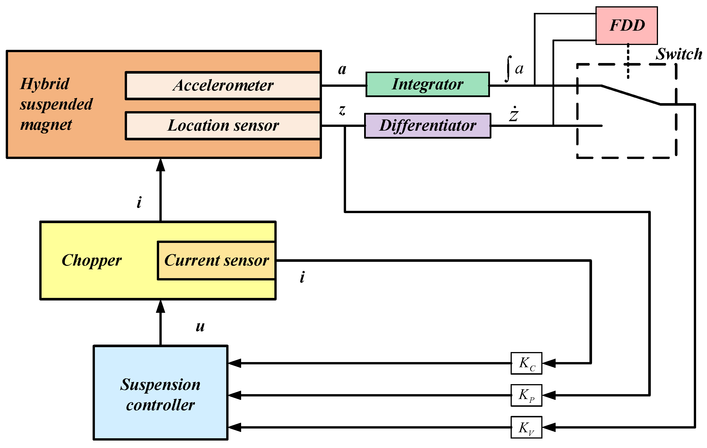
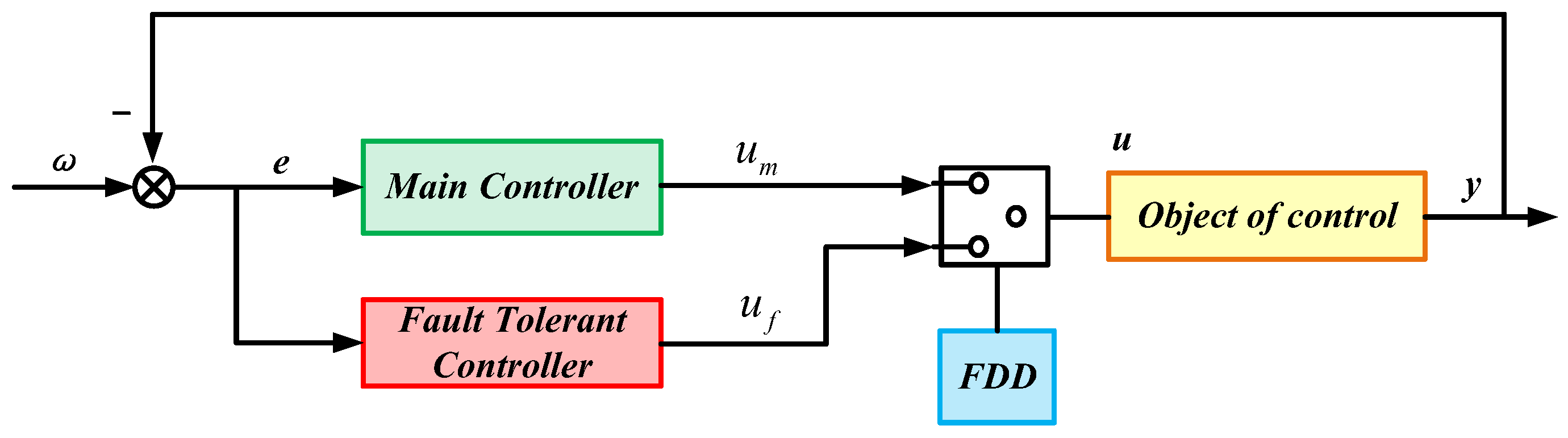
- Fault-tolerant control based on signal reconfiguration
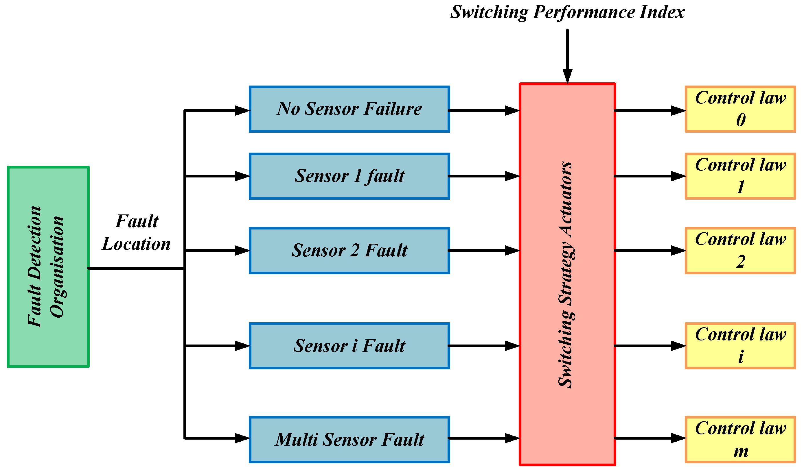
- Fault-tolerant control based on switching
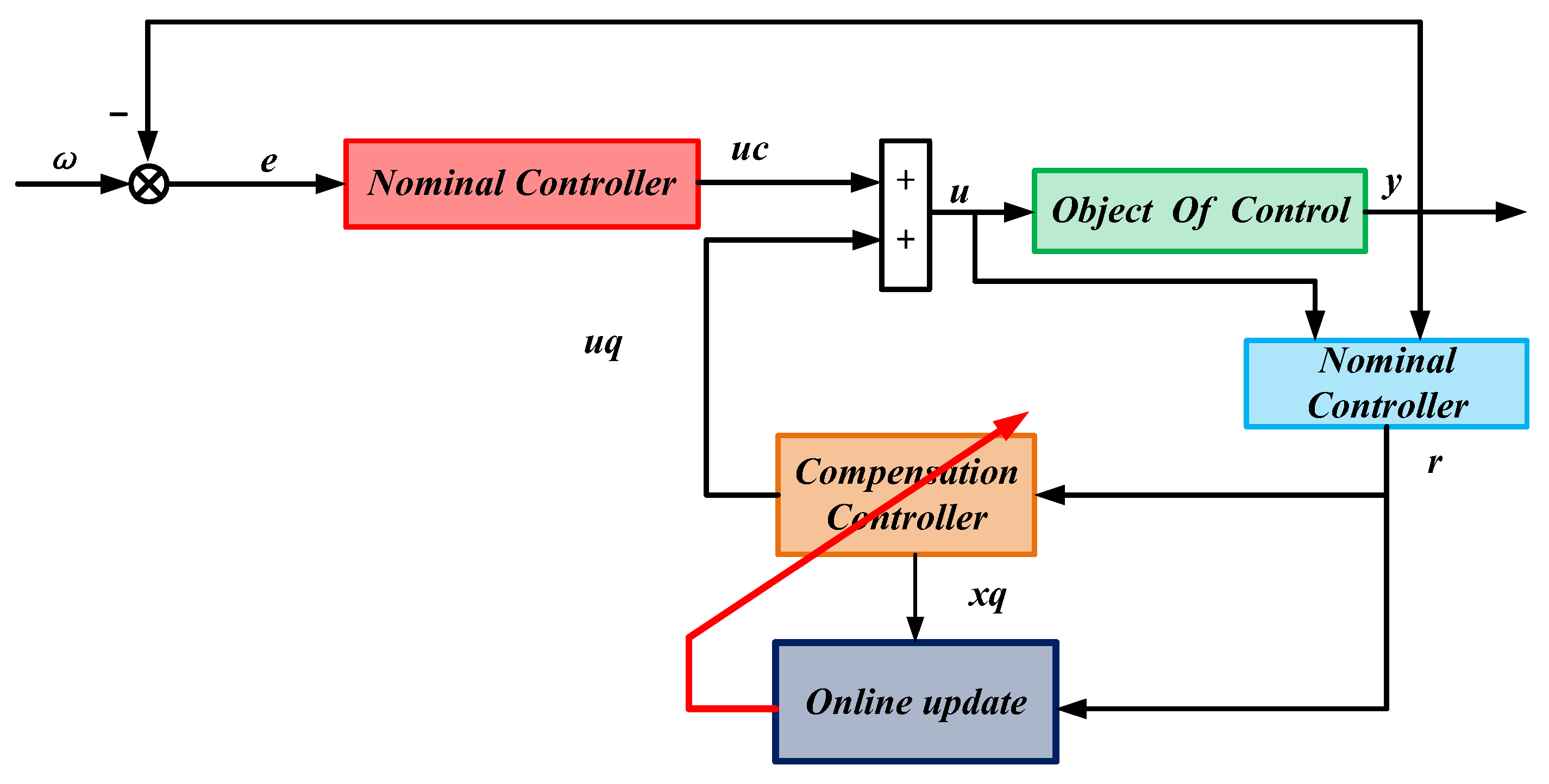
- Fault-tolerant control method based on online optimization
5. Discussion
6. Conclusions
Author Contributions
Funding
Conflicts of Interest
References
- Cascetta, E. Transportation Systems Analysis: Models and Applications; Springer Science & Business Media: Berlin/Heidelberg, Germany, 2009; Volume 29. [Google Scholar]
- Yang, X.; Yan, L.; Shen, Y.; Li, H.; Liu, Y. Dynamic performance analysis and parameters perturbation study of inerter–spring–damper suspension for heavy vehicle. J. Low Freq. Noise Vib. Act. Control 2021, 40, 1335–1350. [Google Scholar]
- Raouf, I.; Khan, A.; Khalid, S.; Sohail, M.; Azad, M.M.; Kim, H.S. Sensor-based prognostic health management of advanced driver assistance system for autonomous vehicles: A recent survey. Mathematics 2022, 10, 3233. [Google Scholar] [CrossRef]
- Maybeck, P.S. Multiple model adaptive algorithms for detecting and compensating sensor and actuator/surface failures in aircraft flight control systems. Int. J. Robust Nonlinear Control 1999, 9, 1051–1070. [Google Scholar]
- Zio, E. Reliability engineering: Old problems and new challenges. Reliab. Eng. Syst. Saf. 2009, 94, 125–141. [Google Scholar]
- Härkegård, O.; Glad, S.T. Resolving actuator redundancy—Optimal control vs. control allocation. Automatica 2005, 41, 137–144. [Google Scholar]
- Hopkins, A.L.; Smith, T.B.; Lala, J.H. FTMP—A highly reliable fault-tolerant multiprocess for aircraft. Proc. IEEE 1978, 66, 1221–1239. [Google Scholar]
- Witczak, M. Fault Diagnosis and Fault-Tolerant Control Strategies for Non-Linear Systems; Lectures Notes in Electrical Engineering; Springer International Publisher: Berlin/Heidelberg, Germany, 2014; Volume 266. [Google Scholar]
- Rotondo, D.; Nejjari, F.; Puig, V. A virtual actuator and sensor approach for fault tolerant control of LPV systems. J. Process Control 2014, 24, 203–222. [Google Scholar]
- Li, T.; Zhang, Y.; Gordon, B.W. Passive and active nonlinear fault-tolerant control of a quadrotor unmanned aerial vehicle based on the sliding mode control technique. Proc. Inst. Mech. Eng. Part I J. Syst. Control Eng. 2013, 227, 12–23. [Google Scholar]
- Mahmoud, M.; Jiang, J.; Zhang, Y. Active Fault Tolerant Control Systems: Stochastic Analysis and Synthesis; Springer Science & Business Media: Berlin/Heidelberg, Germany, 2003; Volume 287. [Google Scholar]
- Jiang, J. Fault-tolerant control systems-an introductory overview. Acta Autom. Sin. 2005, 31, 161–174. [Google Scholar]
- Jiang, J.; Yu, X. Fault-tolerant control systems: A comparative study between active and passive approaches. Annu. Rev. Control 2012, 36, 60–72. [Google Scholar]
- Amin, A.A.; Hasan, K.M. A review of fault tolerant control systems: Advancements and applications. Measurement 2019, 143, 58–68. [Google Scholar]
- Sadeghzadeh, I.; Zhang, Y. A review on fault-tolerant control for unmanned aerial vehicles (UAVs). Infotech@ Aerosp. 2011, 2011, 1472. [Google Scholar]
- Alwi, H.; Edwards, C. Fault detection and fault-tolerant control of a civil aircraft using a sliding-mode-based scheme. IEEE Trans. Control Syst. Technol. 2008, 16, 499–510. [Google Scholar]
- Wang, X.; Wang, S.; Yang, Z.; Zhang, C. Active fault-tolerant control strategy of large civil aircraft under elevator failures. Chin. J. Aeronaut. 2015, 28, 1658–1666. [Google Scholar]
- Li, T.; Tang, X.; Ge, J.; Fei, S. Event-based fault-tolerant control for networked control systems applied to aircraft engine system. Inf. Sci. 2020, 512, 1063–1077. [Google Scholar]
- Tayyeb, M.; Riaz, U.; Amin, A.A.; Saleem, O.; Arslan, M.; Shahbaz, M.H. Design of highly redundant fault tolerant control for aircraft elevator system. J. Appl. Eng. Sci. 2021, 19, 37–47. [Google Scholar]
- Wang, R.; Wang, J. Fault-tolerant control with active fault diagnosis for four-wheel independently driven electric ground vehicles. IEEE Trans. Veh. Technol. 2011, 60, 4276–4287. [Google Scholar]
- Guo, B.; Chen, Y. Robust adaptive fault-tolerant control of four-wheel independently actuated electric vehicles. IEEE Trans. Ind. Inf. 2019, 16, 2882–2894. [Google Scholar]
- Zhang, G.; Zhang, H.; Huang, X.; Wang, J.; Yu, H.; Graaf, R. Active fault-tolerant control for electric vehicles with independently driven rear in-wheel motors against certain actuator faults. IEEE Trans. Control Syst. Technol. 2015, 24, 1557–1572. [Google Scholar]
- Wang, R.; Wang, J. Fault-Tolerant Control for Electric Ground Vehicles with Independently-Actuated In-Wheel Motors. J. Dyn. Syst. Meas. Control 2012, 134, 021014. [Google Scholar]
- Lala, J.H.; Nagle, G.; Harper, R.E. Verification Methodology of Fault-Tolerant, Fail-Safe Computers Applied to MAGLEV Control Computer Systems; United States. Department of Transportation. Federal Railroad Administration: Washington, DC, USA, 1993.
- Ji, W.; Lv, D.; Luo, S.; Sun, Y. Multiple Models-Based Fault Tolerant Control of Levitation Module of Maglev Vehicles against Partial Actuator Failures. IEEE Trans. Veh. Technol. 2024. [Google Scholar] [CrossRef]
- Song, Q.; Song, Y.-D. Data-based fault-tolerant control of high-speed trains with traction/braking notch nonlinearities and actuator failures. IEEE Trans. Neural Netw. 2011, 22, 2250–2261. [Google Scholar]
- Chen, C.; Xu, J.; Rong, L.; Ji, W.; Lin, G.; Sun, Y. Neural-network-state-observation-based adaptive inversion control method of maglev train. IEEE Trans. Veh. Technol. 2022, 71, 3660–3669. [Google Scholar]
- Abbaspour, A.; Mokhtari, S.; Sargolzaei, A.; Yen, K.K. A Survey on Active Fault-Tolerant Control Systems. Electronics 2020, 9, 1513. [Google Scholar] [CrossRef]
- Ding, S. Advanced Methods for Fault Diagnosis and Fault Tolerant Control; Springer: Berlin/Heidelberg, Germany, 2021. [Google Scholar]
- Yin, S.; Xiao, B.; Ding, S.X.; Zhou, D. A review on recent development of spacecraft attitude fault tolerant control system. IEEE Trans. Ind. Electron. 2016, 63, 3311–3320. [Google Scholar]
- Zhang, W.; Xu, D.; Enjeti, P.N.; Li, H.; Hawke, J.T.; Krishnamoorthy, H.S. Survey on fault-tolerant techniques for power electronic converters. IEEE Trans. Power Electron. 2014, 29, 6319–6331. [Google Scholar]
- Wang, Z. Electrical System on Maglev Trains with Middle and Low Speed. Roll. Stock. 2014, 52, 22–24. [Google Scholar]
- Wang, Z.; Long, Z.; LI, X. Simulation Analysis of Levitation System of High-Speed Maglev Trains with Joint Structure. Southwest Jiaotong Univ. 2022, 59, 590–599. [Google Scholar]
- Kitchenham, B.; Charters, S. Guidelines for Performing Systematic Literature Reviews in Software Engineering; Technical Report EBSE-2007-01; School of Computer Science and Mathematics, Keele University: Keele, UK, 2007. [Google Scholar]
- Kitchenham, B. Procedures for Performing Systematic Reviews; Technical Report TR/SE-0401; Keele University: Keele, UK, 2004; Volume 33, pp. 1–26. [Google Scholar]
- Sharp, R.; Crolla, D. Road vehicle suspension system design—A review. Veh. Syst. Dyn. 1987, 16, 167–192. [Google Scholar]
- Liu, Z.; Long, Z.; Li, X. Maglev train overview. In Maglev Trains; Springer: Berlin/Heidelberg, Germany, 2015; pp. 1–28. [Google Scholar]
- Mohajer, N.; Abdi, H.; Nahavandi, S. Dynamic response multiobjective optimization of road vehicle ride quality—A computational multibody system approach. Proc. Inst. Mech. Eng. Part K J. Multi-Body Dyn. 2017, 231, 316–332. [Google Scholar]
- Bruni, S.; Vinolas, J.; Berg, M.; Polach, O.; Stichel, S. Modelling of suspension components in a rail vehicle dynamics context. Veh. Syst. Dyn. 2011, 49, 1021–1072. [Google Scholar]
- Bauer, W. Hydropneumatic Suspension Systems; Springer: Berlin/Heidelberg, Germany, 2011. [Google Scholar]
- Liu, Z.; Long, Z.; Li, X. Maglev Trains: Key Underlying Technologies; Springer: Berlin, Germany, 2015. [Google Scholar]
- Han, H.-S.; Kim, D.-S. Magnetic Levitation: Maglev Technology and Applications; Springer: New York, NY, USA, 2016. [Google Scholar]
- Sugahara, Y.; Takigami, T.; Sampei, M. Suppressing vertical vibration in railway vehicles through primary suspension damping force control. J. Syst. Des. Dyn. 2007, 1, 224–235. [Google Scholar]
- Pazooki, A.; Rakheja, S.; Cao, D. Modeling and validation of off-road vehicle ride dynamics. Mech. Syst. Sig. Process. 2012, 28, 679–695. [Google Scholar]
- Savaresi, S.M.; Poussot-Vassal, C.; Spelta, C.; Sename, O.; Dugard, L. Semi-Active Suspension Control Design for Vehicles; Butterworth-Heinemann: Boston, MA, USA, 2010. [Google Scholar]
- Paksoy, M.; Metin, M. Nonlinear adaptive semiactive control of a half-vehicle model via hardware in the loop simulation. Turk. J. Electr. Eng. Comput. Sci. 2020, 28, 1612–1630. [Google Scholar]
- Goodarzi, A.; Lu, Y.; Khajepour, A. Analysis and Design of Suspension Mechanisms. In Vehicle Suspension System Technology and Design; Springer: Cham, Switzerland, 2023; pp. 27–70. [Google Scholar]
- Du, H.; Li, P.; Ning, D. Vibration Control of Vehicle Suspension Systems; CRC Press: Boca Raton, FL, USA, 2023. [Google Scholar]
- Liu, Y.-J.; Zeng, Q.; Tong, S.; Chen, C.P.; Liu, L. Actuator failure compensation-based adaptive control of active suspension systems with prescribed performance. IEEE Trans. Ind. Electron. 2019, 67, 7044–7053. [Google Scholar]
- Zhang, X.; Lu, J.Y.; Long, X.L. Research on the Model-Building Error for EMS Maglev Vehicles. In Proceedings of the Applied Mechanics and Materials, Chongqing, China, 18–19 December 2014. [Google Scholar]
- Boudali, H.; Williams, R.; Giras, T. A Simulink simulation framework of a MagLev model. Proc. Inst. Mech. Eng. Part F J. Rail Rapid Transit 2003, 217, 227–236. [Google Scholar]
- Whidborne, J.F. EMS control system design for a maglev vehicle—A critical system. Automatica 1993, 29, 1345–1349. [Google Scholar]
- Suebsomran, A. Adaptive neural network control of electromagnetic suspension system. Int. J. Rob. Autom. 2014, 29, 144–154. [Google Scholar]
- Sinha, P.K. Electromagnetic Suspension Dynamics & Control; Savoy Place: London, UK, 1987. [Google Scholar]
- Zhao, C. Dynamics of maglev vehicle/guideway systems (I)—Magnet/rail interaction and system stability. J. Mech. Eng. 2005, 41, 1–10. [Google Scholar]
- Guo, F.; Hu, F.; Wu, S.; He, F.; Liu, J.; Wu, X. System dynamics in structural strength and vibration fatigue life assessment of the swing bar for high-speed maglev train. Int. J. Mech. Syst. Dyn. 2022, 2, 178–189. [Google Scholar]
- Gong, J. Structural form and dynamic characteristics of high-speed maglev separated track beam. J. Vib. Eng. Technol. 2022, 10, 2283–2291. [Google Scholar]
- Lee, H.-W.; Kim, K.-C.; Lee, J. Review of maglev train technologies. IEEE Trans. Magn. 2006, 42, 1917–1925. [Google Scholar]
- Li, F.; Sun, Y.; Xu, J.; He, Z.; Lin, G. Control methods for levitation system of EMS-type maglev vehicles: An overview. Energies 2023, 16, 2995. [Google Scholar] [CrossRef]
- Piłat, A. Testing performance and reliability of magnetic suspension controllers. IFAC Proc. Vol. 2009, 42, 164–167. [Google Scholar]
- Zhang, L.P.; Gong, D.L. Passive fault-tolerant control for vehicle active suspension system based on H2/H∞ approach. J. Vibroeng. 2018, 20, 1828–1849. [Google Scholar]
- Ahmad, I.; Ge, X.; Han, Q.-L.; Cao, Z. Dynamic event-triggered fault-tolerant control of vehicle active suspension systems. In Proceedings of the IECON 2020 the 46th Annual Conference of the IEEE Industrial Electronics Society, Singapore, 18–21 October 2020; pp. 4889–4894. [Google Scholar]
- Xiong, J.; Chang, X.H.; Park, J.H.; Li, Z.M. Nonfragile fault-tolerant control of suspension systems subject to input quantization and actuator fault. Int. J. Robust Nonlinear Control 2020, 30, 6720–6743. [Google Scholar]
- Viadero-Monasterio, F.; Boada, B.L.; Zhang, H.; Boada, M.J.L. Integral-based event triggering actuator fault-tolerant control for an active suspension system under a networked communication scheme. IEEE Trans. Veh. Technol. 2023, 72, 13848–13860. [Google Scholar]
- Viadero-Monasterio, F.; Boada, B.; Boada, M.; Díaz, V. H∞ dynamic output feedback control for a networked control active suspension system under actuator faults. Mech. Syst. Sig. Process. 2022, 162, 108050. [Google Scholar]
- Wong, P.K.; Wang, H.; Zhao, J. Robust finite-time fault-tolerant control for vehicle height and posture regulation with air suspension system subject to actuator faults, uncertainties and external disturbance. Nonlinear Dyn. 2023, 111, 10113–10130. [Google Scholar]
- Cao, F.; Sun, H.; Li, Y.; Tong, S. Fuzzy adaptive fault-tolerant control for a class of active suspension systems with time delay. Int. J. Fuzzy Syst. 2019, 21, 2054–2065. [Google Scholar]
- Zhang, Y.; Liu, L. Adaptive fault tolerant control of active suspension systems with time-varying displacement and velocity constraints. IEEE Access 2020, 8, 10847–10856. [Google Scholar]
- Kazemipour, A.; Novinzadeh, A.B. Adaptive fault-tolerant control for active suspension systems based on the terminal sliding mode approach. Proc. Inst. Mech. Eng. Part C J. Mech. Eng. Sci. 2020, 234, 501–511. [Google Scholar]
- Zhao, W.; Gu, L. Adaptive Fault Tolerant Controller for Nonlinear Active Suspension. In Proceedings of the International Conference on Intelligent Robotics and Applications, Hangzhou, China, 5–7 July 2023; pp. 3–11. [Google Scholar]
- Kou, F.; Chen, C.; Xiao, W.; Hu, K. Study on Adaptive Sliding Mode Fault-tolerant Control of 1/4 Vehicle Electromagnetic Suspension. J. Phys. Conf. Ser. 2023, 2528, 012025. [Google Scholar]
- Sun, J.; Liu, Q.; Gu, L. Second Order Sliding Mode Fault Tolerant Control of Active Suspension Systems. Mech. Sci. Technol. Aerosp. Eng. 2021, 40, 1370–1377. [Google Scholar]
- Zhang, X.; Liu, L.; Liu, Y.J. Adaptive fuzzy fault-tolerant control of seat active suspension systems with actuator fault. IET Control Theory Appl. 2021, 15, 1104–1114. [Google Scholar]
- Li, Y.; Ma, S.; Li, K.; Tong, S. Adaptive fuzzy output feedback fault-tolerant control for active suspension systems. IEEE Trans. Intell. Veh. 2023, 9, 2469–2478. [Google Scholar]
- Yang, H.; Liu, Q.; Zhang, Y.; Yu, F. An adaptive sliding mode fault-tolerant control for semi-active suspensions with magnetorheological dampers based on TS fuzzy vehicle models. J. Vib. Control 2023, 29, 251–264. [Google Scholar]
- Xie, Z.; You, W.; Wong, P.K.; Li, W.; Ma, X.; Zhao, J. Robust fuzzy fault tolerant control for nonlinear active suspension systems via adaptive hybrid triggered scheme. Int. J. Adapt Control Signal Process. 2023, 37, 1608–1627. [Google Scholar]
- Mrazgua, J.; Ouahi, M. Fuzzy fault-tolerant H∞ control approach for nonlinear active suspension systems with actuator failure. Procedia Comput. Sci. 2019, 148, 465–474. [Google Scholar]
- Pang, H.; Yang, J.; Liu, X. Sliding-Mode Fault Tolerant Controller Design for Vehicle Active Suspension Systems Based on T-S Fuzzy Model. Eng. Mech. 2019, 2, 229–238. [Google Scholar]
- Pham, T.P. LPV Observer and Fault-Tolerant Control of Vehicle Dynamics: Application to an Automotive Semi-Active Suspension System. Ph.D. Thesis, Université de Grenoble, Grenoble, France, 2019. [Google Scholar]
- Han, S.; Zhou, J.; Chen, Y.; Zhang, Y.; Tang, G.; Wang, L. Active Fault-Tolerant Control for Discrete Vehicle Active Suspension via Reduced-Order Observer. IEEE Trans. Syst. Man Cybern. Syst. 2020, 51, 6701–6711. [Google Scholar]
- Pang, H.; Luo, J.; Wang, M.; Wang, L. A stability guaranteed nonfragile fault-tolerant control approach for Markov-type vehicle active suspension system subject to faults and disturbances. J. Vib. Control 2024, 30, 929–942. [Google Scholar]
- Wang, H. Active fault tolerance control for active suspension with control input time-delay and actuator gain variation fault. Int. J. Heavy Veh. Syst. 2020, 27, 703–722. [Google Scholar]
- Sun, J.; Cong, J.; Gu, L.; Dong, M. Fault-tolerant control for vehicle with vertical and lateral dynamics. Proc. Inst. Mech. Eng. Part D J. Automob. Eng. 2019, 233, 3165–3184. [Google Scholar]
- Kwon, B.-s.; Kang, D.; Yi, K. Fault-tolerant control with state and disturbance observers for vehicle active suspension systems. Proc. Inst. Mech. Eng. D J. Autom. Eng. 2020, 234, 1912–1929. [Google Scholar]
- Du, X.; Han, G.; Yu, M.; Peng, Y.; Xu, X.; Fu, J. Fault detection and fault tolerant control of vehicle semi-active suspension system with magneto-rheological damper. Smart Mater. Struct. 2020, 30, 014004. [Google Scholar]
- Kou, F.; Wu, J.; Gao, J.; Wu, D.; Chen, R. Active Fault-Tolerant Control Based on the Fault of Electromagnetic Hybrid Active Suspension. Shock Vib. 2021, 2021, 4273698. [Google Scholar]
- Abboudi, A.; Bououden, S.; Chadli, M.; Boulkaibet, I.; Neji, B. Observer-based fault-tolerant predictive control for LPV systems with sensor faults: An active car suspension application. Appl. Sci. 2022, 12, 684. [Google Scholar] [CrossRef]
- Morato, M.M.; Sename, O.; Dugard, L. Design and analysis of several state-feedback fault-tolerant control strategies for semi-active suspensions. IFAC-PapersOnLine 2019, 52, 48–53. [Google Scholar]
- Pang, H.; Liu, X.; Shang, Y.; Yao, R. A Hybrid Fault-Tolerant Control for Nonlinear Active Suspension Systems Subjected to Actuator Faults and Road Disturbances. Complexity 2020, 2020, 1874212. [Google Scholar]
- Ho, C.M.; Dao, H.V.; Tran, D.T.; Ahn, K.K. Design of Observer-Based Adaptive Fuzzy Fault-Tolerant Control for Pneumatic Active Suspension with Displacement Constraint. In Proceedings of the 2023 International Conference on System Science and Engineering (ICSSE), Ho Chi Minh, Vietnam, 27–28 July 2023; pp. 184–189. [Google Scholar]
- Ho, C.M.; Ahn, K.K. Observer based adaptive neural networks fault-tolerant control for pneumatic active suspension with vertical constraint and sensor fault. IEEE Trans. Veh. Technol. 2022, 72, 5862–5876. [Google Scholar]
- Pang, H.; Shang, Y.; Yang, J. An adaptive sliding mode–based fault-tolerant control design for half-vehicle active suspensions using T–S fuzzy approach. J. Vib. Control 2020, 26, 1411–1424. [Google Scholar]
- Pang, H.; Shang, Y.; Wang, P. Design of a sliding mode observer-based fault tolerant controller for automobile active suspensions with parameter uncertainties and sensor faults. IEEE Access 2020, 8, 186963–186975. [Google Scholar]
- Luo, J.; Pang, H.; Wang, M.; Yao, R. PI observer-based fault-tolerant tracking controller for automobile active suspensions. IEEE Access 2022, 10, 47203–47218. [Google Scholar]
- Michail, K.; Zolotas, A.; Goodall, R.M. Ems systems: Optimised sensor configurations for control and sensor fault tolerance. In Proceedings of the International Symposium on Speed-Up, Safety and Service Technology for Railway and Maglev Systems 2009, Niigata, Japan, 16–19 June 2009. [Google Scholar]
- Zhang, Z. Research on Fault-Tolerant Control Technology for Single Electromagnet Suspension System of High Speed Maglev Train. Master’s Thesis, National University of Defense Technology, Changsha, China, 2006. [Google Scholar]
- Zhai, M.; Li, X.; Long, Z. Research on Redundancy and Fault-Tolerant Control Technology of Levitation Join-Structure in High Speed Maglev Train. In Proceedings of the 3rd International Conference on Electrical and Information Technologies for Rail Transportation (EITRT) 2017: Electrical Traction, Changsha, China, 20–22 October 2017; pp. 671–678. [Google Scholar]
- Chen, S.; Chen, J.; Xu, J.Q.; Rong, L.J.; Lin, G.B.; Sun, Y.G.; Jiang, F.J. A Redundant Fault-Tolerant Control System for the Suspension Frame of EMS High-Speed Maglev Trains. CN113665368A, 19 November 2021. Available online: https://d.wanfangdata.com.cn/patent/ChJQYXRlbnROZXdTMjAyMzA5MDESEENOMjAyMTEwODkwNTE2LjgaCDFzbzk5dDdy (accessed on 6 April 2024).
- Long, Z.; Xue, S.; Yu, L. Distributed Active Fault-tolerant Control for Module Suspension System of Maglev Train. J. China Railw. Soc. 2009, 31, 38–43. [Google Scholar]
- Liang, S.; Zeng, J.; Jin, L.; Long, Z. Computer Design and Test of Suspension Control Based on Two-machine Hot Standby for Speed Maglev Train. In Proceedings of the 2020 39th Chinese Control Conference (CCC), Shenyang, China, 27–29 July 2020; pp. 4147–4152. [Google Scholar]
- Deliparaschos, K.M.; Michail, K.; Zolotas, A. On the issue of LQG embedded control realization in a Maglev system. In Proceedings of the 2017 25th Mediterranean Conference on Control and Automation (MED), Valletta, Malta, 3–6 July 2017; pp. 1379–1384. [Google Scholar]
- Deliparaschos, K.M.; Michail, K.; Tzafestas, S.G.; Zolotas, A.C. Optimised sensor selection for control: A hardware-in-the-loop realization on FPGA for an EMS system. In Proceedings of the 2013 Conference on Control and Fault-Tolerant Systems (SysTol), Nice, France, 9–11 October 2013; pp. 727–732. [Google Scholar]
- Long, Z.; Xue, S.; Chen, H. Passive Fault Tolerant Control for Suspension System of Maglev Train Based on LMI. Comput. Simul. 2008, 25, 265–268. [Google Scholar]
- Fang, T.Q.; Wei, Y. Research on robust H8 fault-tolerant control for uncertain suspension system with time delay. In Proceedings of the 2012 International Conference on Industrial Control and Electronics Engineering, Xi’an, China, 23–25 August 2012; pp. 1994–1997. [Google Scholar]
- Zhai, M.; Li, X.; Long, Z. Fault-tolerant control strategy for the suspension module of EMS High-speed maglev train. In Proceedings of the 2017 IEEE 2nd Information Technology, Networking, Electronic and Automation Control Conference (ITNEC), Chengdu, China, 15–17 December 2017; pp. 64–67. [Google Scholar]
- Yang, S.; Wu, J. Fault-tolerant networked control systems. In Proceedings of the 2013 CACS International Automatic Control Conference (CACS), Nantou, Taiwan, 2–4 December 2013; pp. 186–191. [Google Scholar]
- Sun, Y.; Li, F.; Lin, G.; Xu, J.; He, Z. Adaptive fault-tolerant control of high-speed maglev train suspension system with partial actuator failure: Design and experiments. J. Zhejiang Univ. Sci. A 2023, 24, 272–283. [Google Scholar]
- Jia, M.; Liu, X.; Zhang, X.; Zhang, Y. Robust Adaptive Fault-Tolerant Control for Uncertain Magnetic Levitation System. In Proceedings of the 2022 IEEE 17th International Conference on Control & Automation (ICCA), Naples, Italy, 27–30 June 2022; pp. 50–55. [Google Scholar]
- Liu, J.; Liu, X.; Zhang, M. Robust Immersion and Invariance Adaptive Synchronization Control with Disturbance Observer for Maglev Module with Output Constraint. 2021. Available online: https://www.researchsquare.com/article/rs-731192/v1 (accessed on 1 December 2023). [CrossRef]
- Hu, X.; Song, Q.; Ge, M. Fractional-Order Adaptive Fault-Tolerant Tracking Control for High Speed Trains. In Proceedings of the 2020 Chinese Control and Decision Conference (CCDC), Hefei, China, 22–24 August 2020; pp. 2943–2948. [Google Scholar]
- Tepljakov, A.; Alagoz, B.B.; Gonzalez, E.; Petlenkov, E.; Yeroglu, C. Model reference adaptive control scheme for retuning method-based fractional-order PID control with disturbance rejection applied to closed-loop control of a magnetic levitation system. J. Circuits Syst. Comput. 2018, 27, 1850176. [Google Scholar]
- Xu, Y.; Long, Z.; Zhao, Z.; Zhai, M.; Wang, Z. Real-time stability performance monitoring and evaluation of maglev trains’ levitation system: A data-driven approach. IEEE Trans. Intell. 2020, 23, 1912–1923. [Google Scholar]
- Wang, Z.; Long, Z.; Luo, J.; He, Z.; Li, X. Data driven state monitoring of maglev system with experimental analysis. IEEE Access 2020, 8, 79104–79113. [Google Scholar]
- Zhou, X.; Wang, P.; Long, Z. Fault detection for suspension system of maglev trains based on historical health data. IEEE Access 2020, 8, 134290–134302. [Google Scholar]
- Wang, Z.; Long, Z.; Luo, J.; He, Z.; Li, X. A data-driven fault diagnosis of high speed maglev train levitation system. Int. J. Adapt Control Signal Process. 2023, 37, 2671–2689. [Google Scholar]
- Wang, P.; Long, Z.; Xu, Y. Component-level fault detection for suspension system of maglev trains based on autocorrelation length and stable kernel representation. IEEE Trans. Veh. Technol. 2021, 70, 7594–7604. [Google Scholar]
- Liang, S.; Long, Z.; Zhou, X.; Wang, P. Optimized KLD-Based Fault Detection Method for Complex System Under Multi-Operation Conditions. IEEE Access 2020, 8, 163917–163925. [Google Scholar]
- Deliparaschos, K.M.; Michail, K.; Zolotas, A.C. Facilitating autonomous systems with AI-based fault tolerance and computational resource economy. Electronics 2020, 9, 788. [Google Scholar] [CrossRef]
- Mei, Z.; Luo, J.; Wang, Z. Research on Fault Modeling and Fault Diagnosis of Maglev Suspension System. In Proceedings of the 2020 Chinese Automation Congress (CAC), Shanghai, China, 6–8 November 2020; pp. 4032–4036. [Google Scholar]
- Yang, B.; Luo, J.; Wang, Z. Research on Fault Diagnosis of Actuator in the Suspension System of Maglev Trains Based on Robust Observer. In Proceedings of the 2021 13th International Symposium on Linear Drives for Industry Applications (LDIA), Wuhan, China, 1–3 July 2021; pp. 1–4. [Google Scholar]
- Yu, X.; Wu, W.; Niu, G. A hybrid fault isolation method for acceleration sensors in maglev train using auto-regression model and improved extended state observer. In Proceedings of the 2022 Global Reliability and Prognostics and Health Management (PHM-Yantai), Yantai, China, 13–16 October 2022; pp. 1–7. [Google Scholar]
- Luo, J. Research on Fault Diagnosis Method of Suspension System of High Speed Maglev Train. Master’s Thesis, National University of Defense Technology, Changsha, China, 2020. [Google Scholar]
- Wang, S.-M.; Wang, Y.-W.; Ni, Y.-Q.; Lu, Y. Real-Time Malfunction Detection of Maglev Suspension Controllers. Mathematics 2023, 11, 4045. [Google Scholar] [CrossRef]
- Zhao, Y.; Peng, F.; Ren, L.; Lin, G.; Xu, J. A levitation condition awareness architecture for low-speed maglev train based on data-driven random matrix analysis. IEEE Access 2020, 8, 176575–176587. [Google Scholar]
- Wang, Z.; Long, Z.; Li, X. Fault analysis and tolerant control for high speed pems maglev train end joint structure with disturbance rejection. J. Electr. Eng. Technol. 2019, 14, 1357–1366. [Google Scholar]
- Hou, Z.; Gan, W.; Xu, S.; Guo, W.; Chen, Q.; Wang, W.; Chen, K. Fault detection of accelerometer and fault-tolerant control for maglev. In Proceedings of the 2019 IEEE Vehicle Power and Propulsion Conference (VPPC), Hanoi, Vietnam, 14–17 October 2019; pp. 1–5. [Google Scholar]
- Li, J.; Ding, K.; Sun, J.; Wang, C.; Zhao, H.; Zhu, H. A Practical Control Strategy for Magnetic Levitation System against Two Probes Failures. In Proceedings of the 2020 39th Chinese Control Conference (CCC), Shenyang, China, 27–29 July 2020; pp. 5577–5583. [Google Scholar]
- Wang, Z.; Long, Z.; Li, X. Fault tolerant control for joint structure in PEMS high speed maglev train. Asian J. Control 2021, 23, 486–498. [Google Scholar]
- Zuo, Z.; Wang, Z.; Deng, P.; Long, Z. Research on fault tolerant control of guidance system of high speed Maglev train. In Proceedings of the 2019 Chinese Automation Congress (CAC), Hangzhou, China, 22–24 November 2019; pp. 5821–5826. [Google Scholar]
- Michail, K.; Zolotas, A.C.; Goodall, R.M. Optimised sensor selection for control and fault tolerance of electromagnetic suspension systems: A robust loop shaping approach. ISA Trans. 2014, 53, 97–109. [Google Scholar]
- Michail, K.; Zolotas, A.C.; Goodall, R.M.; Halikias, G. Optimal selection for sensor fault tolerant control of an EMS system via loop-shaping robust control. In Proceedings of the 2011 19th Mediterranean Conference on Control & Automation (MED), Corfu, Greece, 20–23 June 2011; pp. 1112–1117. [Google Scholar]
- Long, Z.; Luo, J.; Wang, Q. Research on Permanent Magnet Electromagnetic Hybrid Suspension System Based on Joint Structure about Fault Tolerant Control. In Proceedings of the 2018 Chinese Automation Congress (CAC), Xi’an, China, 30 November–2 December 2018; pp. 3307–3311. [Google Scholar]
- Zhai, M.; Long, Z.; Li, X. Fault-tolerant control of magnetic levitation system based on state observer in high speed maglev train. IEEE Access 2019, 7, 31624–31633. [Google Scholar]
- Guang, H.; Yun, L.; Zhiqiang, L.; Zhide, J. Research on fault tolerant control technology based on networked control system of maglev train. In Proceedings of the 2010 International Conference on Intelligent System Design and Engineering Application, Changsha, China, 13–14 October 2010; pp. 210–214. [Google Scholar]
- Yetendje, A.; Seron, M.M.; De Doná, J.A. Fault-tolerant switching control of a magnetic levitation syste. IFAC Proc. Vol. 2009, 42, 372–377. [Google Scholar]
- Li, X.; Wang, Z.; Hao, A.; Long, Z. Fault diagnosis and tolerance control for accelerator in maglev system based on signal processing. In Proceedings of the 2014 Prognostics and System Health Management Conference (PHM-2014 Hunan), Zhangjiajie, China, 24–27 August 2014; pp. 131–134. [Google Scholar]
- Zhang, H.; Xie, Y.; Long, Z. Fault detection based on tracking differentiator applied on the suspension system of maglev train. Math. Probl. Eng. 2015, 2015, 1–9. [Google Scholar]
- Yetendje, A.; Seron, M.M.; Doná, J.A.D.; Martínez, J.J. Sensor fault-tolerant control of a magnetic levitation system. Int. J. Robust Nonlinear Control. 2010, 20, 2108–2121. [Google Scholar]
- Chen, H.; Long, Z.; Chang, W. Fault tolerant control research for high-speed maglev system with sensor failure. In Proceedings of the 20066th World Congress on Intelligent Control and Automation, Dalian, China, 21–23 June 2006; pp. 2281–2285. [Google Scholar]
- Jin, L.; Long, Z.; Zeng, J. Research on fault-tolerant control problem for suspension system of medium speed maglev train. In Proceedings of the 201729th Chinese Control and Decision Conference (CCDC), Chongqing, China, 28–30 May 2017; pp. 2993–2998. [Google Scholar]
- Chen, Z.; Wu, Z.; Cai, W.; Liu, X. Optimal Reconfigurable Fault-Tolerant Control for Electromagnetic Suspension System of Maglev Train. In Proceedings of the 2022 41st Chinese Control Conference (CCC), Hefei, China, 25–27 July 2022; pp. 520–525. [Google Scholar]
- Michail, K.; Zolotas, A.C.; Goodall, R.M.; Whidborne, J.F. Optimised configuration of sensors for fault tolerant control of an electro-magnetic suspension system. Int. J. Syst. Sci. 2012, 43, 1785–1804. [Google Scholar]
- Alizadeh, T.; Barzegari, S. Fault tolerant control of electromagnetic suspension system with simultaneous sensor and actuator faults. In Proceedings of the 201510th Asian control conference (ASCC), Kota Kinabalu, Malaysia, 31 May–3 June 2015; pp. 1–6. [Google Scholar]
- Li, Y. Research on Fault Detection and Diagnosis and Fault Tolerant Control of Suspension Control System for Middle-Low Speed Maglev Train. Ph.D. Thesis, National University of Defense Technology, Changsha, China, 2015. [Google Scholar]
- Wang, Z.Q. Fault Diagnosis and Tolerant Control for High Speed Maglev Train Suspension System. Ph.D. Thesis, National University of Defense Technology, Changsha, China, 2019. [Google Scholar]
- Zhai, M.; Li, X.; Long, Z.; Dou, F. Control and Optimization Design of Magnetic Levitation System of Highspeed Maglev Train Based on Youla Parameterization. J. Tongji Univ. 2023, 51, 341–350. [Google Scholar]
- Xin, L.; Jiang, H.; Wen, T.; Long, Z. Data-Driven Optimal Controller Design for Maglev Train: Q-Learning Method. In Proceedings of the 2022 34th Chinese Control and Decision Conference (CCDC), Hefei, China, 15–17 August 2022; pp. 1289–1294. [Google Scholar]
- Wang, Z.; Long, Z.; Li, X. Track irregularity disturbance rejection for maglev train based on online optimization of PnP control architecture. IEEE Access 2019, 7, 12610–12619. [Google Scholar]


| Name | Suspension System | |
|---|---|---|
| Control system | Levitation system of Maglev train | Semi-Active/Active Suspension System of Road Vehicles |
| Control Objective | To keep the suspension gap between the train and the rail within a certain range by precisely controlling the current or voltage in the suspension electromagnet. | Body vibration and body height are controlled by changing the height, shape, and damping of the suspension system. |
| Control Method | Various sophisticated sensors are required to monitor the system status and regulate the control parameters through the control unit. | |
| Reference | Classification | Strengths | Weaknesses |
|---|---|---|---|
| [61,62,63,64,65,66] | Robust fault-tolerant control method | When a fault emerges, fault-tolerant control can be accomplished punctually. Furthermore, the design is simplistic, reducing the design cost and complexity of the control system. | The method can only adapt to a few specific fault conditions and cannot achieve robustness against all faults with one controller, and this method comes at the expense of sacrificing the performance of the system. |
| [67,68,69,70,71,72] | Adaptive fault-tolerant control and sliding mode fault-tolerant control methods | Can be applied to nonlinear systems featuring incomplete feedback, uncertain parameters, and external disturbances. It is capable of preserving the stability of the system under such adverse circumstances and attaining a rapid system response. | |
| [73,74,75,76,77,78] | Intelligent fault-tolerant control method | Does not depend on precise models and possesses strong adaptability, prominent robustness, and high real-time performance. | The selection of fuzzy control rules and membership functions frequently relies on experience and lacks systematicity, potentially resulting in the uncertainty of control effects. |
| Reference | Classification | Machinery |
|---|---|---|
| [79,80,81,82,83] | Fault-tolerant control method based on reconfiguration | This method is predicated on fault detection and diagnosis. Once a fault emerges, the controller is shifted to the predesigned corresponding fault-tolerant controller in accordance with the detected fault, ensuring that the system performance remains largely unchanged before and after the fault. This scheme is applicable to scenarios where the possible fault modes are known beforehand, and the control law can be predetermined offline. The reconfiguration herein encompasses the reconfiguration of sensor signals as well as that of the control law. |
| [84,85,86,87,88,89,90,91,92,93,94] | Fault-tolerant control method based on compensation | This approach lies in restoring or maintaining the performance of the system when it fails by introducing a compensation mechanism. This strategy mitigates the influence of the failure via diverse forms of compensation, allowing the system to keep operating at an acceptable performance level. This method typically involves real-time monitoring and evaluation of the system state, along with the design and implementation of compensation measures for the impact of the failure. |
| Reference | Classification | Machinery | Failure Scenario |
|---|---|---|---|
| [103,104,105,106] | Robust passive fault-tolerant control method | Considering the faults of the active suspension actuator and parameter perturbations in advance, the complex nonlinear and parameter uncertainty issues are converted into the offline design issue of the optimal robust fault-tolerant controller. | Is predominantly utilized in circumstances where the actuator exhibits certain perturbation faults or malfunctions. Meanwhile, in [105], this approach was also employed for potential sensor malfunctions. |
| [27,107,108,109,110,111] | Adaptive fault-tolerant control method | The adaptive fault-tolerant control measures the feedback signal of the controlled object in real-time, compares it with the expected output, and adjusts the parameters of the controller through an adaptive algorithm to precisely describe and control the dynamic characteristics of the controlled object. | Mainly focuses on the faults occurring in the actuator of the suspension system, including the partial failure of the actuator and parameter perturbations. |
| Reference | Classification | Machinery | Application Scenarios |
|---|---|---|---|
| [125,126,127,128,129,130,131,132,133,134,135,136,137] | Fault-tolerant control method based on signal reconfiguration | Based on signal configuration, fault-tolerant control mainly includes configuration for sensors or control law reconstruction for actuators. The fault-tolerant control strategy centered on signal reconfiguration is primarily targeted at the sensors within the levitation system that are directly associated with the computation of the control quantity. | Regarding the faults within the sensors associated with the computational control quantities of the suspension unit, such as faults of gap sensors, acceleration sensors, current sensors, etc. |
| [138,139,140,141,142,143] | Fault-tolerant control based on switching | The general idea of the switching fault-tolerant control method in the magnetic suspension system is to predesign the faults that may occur in the system and to realize the fault-tolerant control strategy through the reconfiguration of the control law when the fault occurs. | It primarily centers on the total failure of the individual suspension point, particularly when a suspension point in the lap structure fails to output the control voltage, leading to the complete inability to control the suspension point. The potential causes for this type of failure encompass drive circuit malfunctions, power supply failures, IGBT failures, etc. Simultaneously, it can also handle the issue of sensor signal switching selection resulting from the failure of certain sensors in the sensor concentration. |
| [144,145,146,147,148] | Fault-tolerant control method based on online optimization | The magnetic levitation-based online optimization-driven active fault-tolerant control system makes use of the system data gathered in real time and dynamically modifies the control strategy via the online optimization algorithm to accommodate the variations caused by minor faults. Mechanistically speaking, this approach is also a fault reconfiguration method. | It primarily focuses on the performance deterioration of system components prior to total failure, encompassing phenomena such as sensor signal bias, alterations in electromagnetic iron features, and variations in analog device characteristics. This is predominantly attributed to factors like mechanical friction, material deformation, and device aging accumulated over the prolonged operation of the suspension system. This kind of fault exhibits traits such as a minor fault amplitude, an uncertain fault trend, and temporal variations. It does not affect the system stability but has an influence on the system performance. |
| Methods | Pros | Cons |
|---|---|---|
| Hardware redundancy method | The hardware redundancy method is both simple and effective, improving the reliability and safety of the magnetic levitation train’s suspension system. | Added complexity to the system, increased costs, and additional components affecting the design and energy efficiency of the train. |
| Passive fault-tolerant control method based on robust control and adaptive control | The structure and parameters of the fault-tolerant controller are not changed before and after the system failure, so it is easy to implement. | The control effect is conservative and can only deal with specific faults, which cannot make full use of the system performance. |
| Passive fault-tolerant control method based on intelligent control | Doesn’t rely on accurate model, strong adaptability, good robustness, and high real-time performance. | The design and parameter tuning of control systems can be relatively complex and require expert knowledge and experience. |
| Active fault-tolerant control method based on signal reconstruction | Can design different reconstruction strategies for different types of failures, flexibly addressing various failure scenarios. | Need accurate fault detection and diagnosis, increases in the system complexity and real-time processing ability of system requirements are put forward. At the same time, there may be performance tradeoffs. |
| Active fault-tolerant control method based on compensation | When a fault is detected, the system response can be actively adjusted to isolate the impact of the fault and ensure the normal operation of other parts of the system. | The design of compensation control is complex and requires some understanding of the system dynamics and potential failures. The effectiveness of compensation control is highly dependent on the accuracy and speed of fault detection, diagnosis, and isolation. |
| Active fault-tolerant control method based on control law switching | More flexible, can design customized fault tolerance strategy for different fault modes; the behavior of the system under fault conditions is more predictable. | The effectiveness of control law switching highly depends on accurate and timely fault detection and diagnosis. The switching of the control law may cause a shock to the system and affect the stability and performance of the system. |
| Active fault-tolerant control method based on online optimization | Strong adaptability, can adapt to the change of system parameters and unknown faults; the control input can be adjusted according to the current state of the system to optimize the performance index. | Complex algorithms and large amounts of computational resources are required, especially when fast responses are required. |
Disclaimer/Publisher’s Note: The statements, opinions and data contained in all publications are solely those of the individual author(s) and contributor(s) and not of MDPI and/or the editor(s). MDPI and/or the editor(s) disclaim responsibility for any injury to people or property resulting from any ideas, methods, instructions or products referred to in the content. |
© 2024 by the authors. Licensee MDPI, Basel, Switzerland. This article is an open access article distributed under the terms and conditions of the Creative Commons Attribution (CC BY) license (https://creativecommons.org/licenses/by/4.0/).
Share and Cite
Ni, F.; Luo, Y.; Xu, J.; Liu, D.; Sun, Y.; Ji, W. Review of Fault-Tolerant Control Methods for Suspension Systems: From Road Vehicles to Maglev Trains. Mathematics 2024, 12, 2576. https://doi.org/10.3390/math12162576
Ni F, Luo Y, Xu J, Liu D, Sun Y, Ji W. Review of Fault-Tolerant Control Methods for Suspension Systems: From Road Vehicles to Maglev Trains. Mathematics. 2024; 12(16):2576. https://doi.org/10.3390/math12162576
Chicago/Turabian StyleNi, Fei, Yifan Luo, Junqi Xu, Dachuan Liu, Yougang Sun, and Wen Ji. 2024. "Review of Fault-Tolerant Control Methods for Suspension Systems: From Road Vehicles to Maglev Trains" Mathematics 12, no. 16: 2576. https://doi.org/10.3390/math12162576
APA StyleNi, F., Luo, Y., Xu, J., Liu, D., Sun, Y., & Ji, W. (2024). Review of Fault-Tolerant Control Methods for Suspension Systems: From Road Vehicles to Maglev Trains. Mathematics, 12(16), 2576. https://doi.org/10.3390/math12162576