
Enhanced Virtual Synchronous Generator with Angular Frequency Deviation Feedforward and Energy Recovery Control for Energy Storage System

 ,
,  , ,
, ,  and
and
Abstract
:1. Introduction
- A linearized model in the form of a transfer function and a state-space model have been developed. The necessity of a significant enhancement of damping properties of the conventional VSG structure to suppress the emerging resonance is proved, which also leads to a significant increase in the ESS nominal energy capacity;
- The structure of the modified current-controlled VSG (CC-VSG) with a feedforward controller and an energy recovery control loop for the battery energy storage system (BESS) is proposed;
- The methodology of tuning the modified CC-VSG on the basis of bandwidth separation of different control loops is formed.
2. Description of the Test System and the Proposed CC-VSG Control Algorithm for BESS
2.1. Microgrid Topology
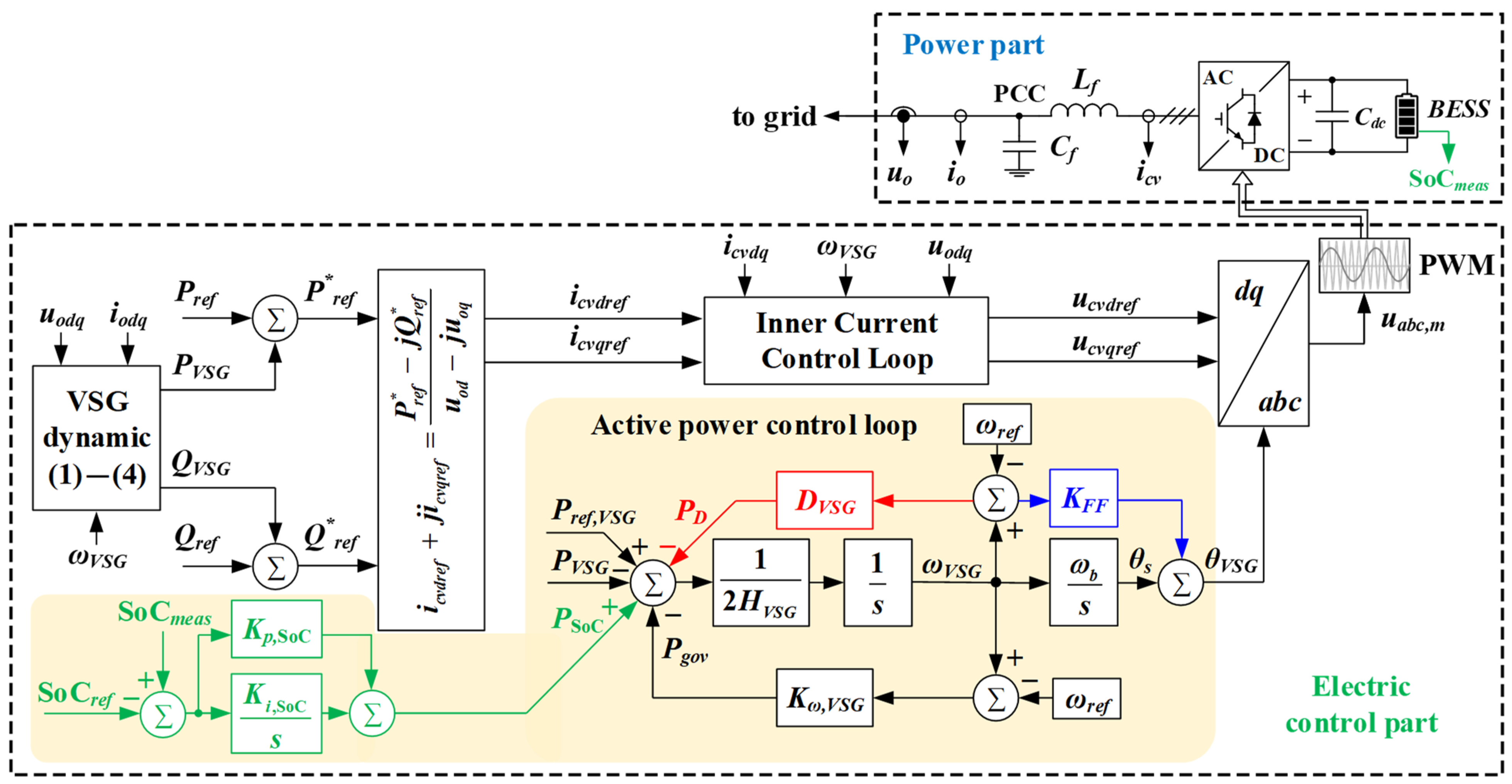
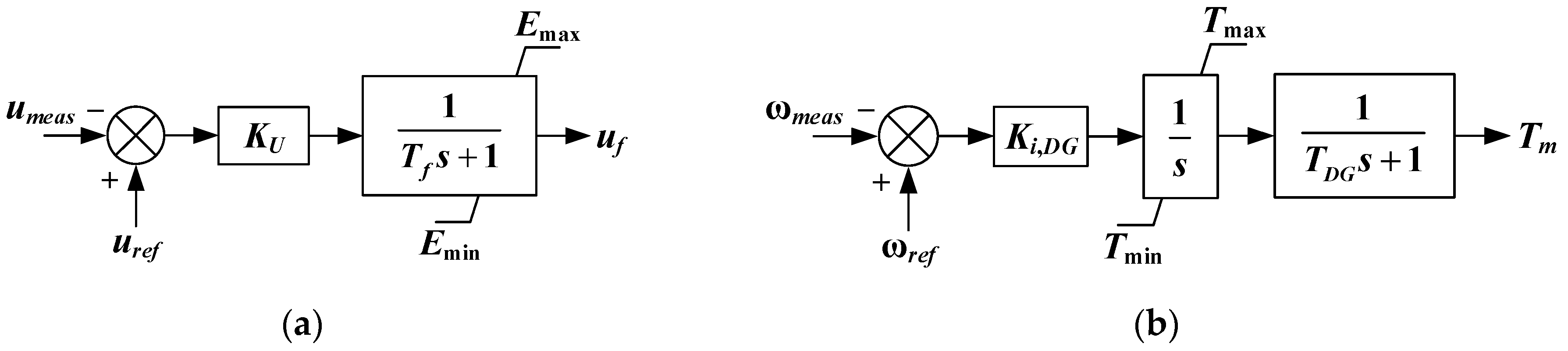
2.2. Structure of the Proposed CC-VSG for BESS
3. Theory Description
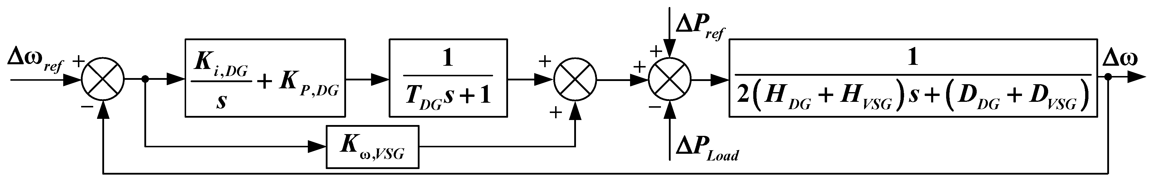
3.1. Modeling a Two-Unit System with a Common Load
3.2. Sizing of BESS for VSG
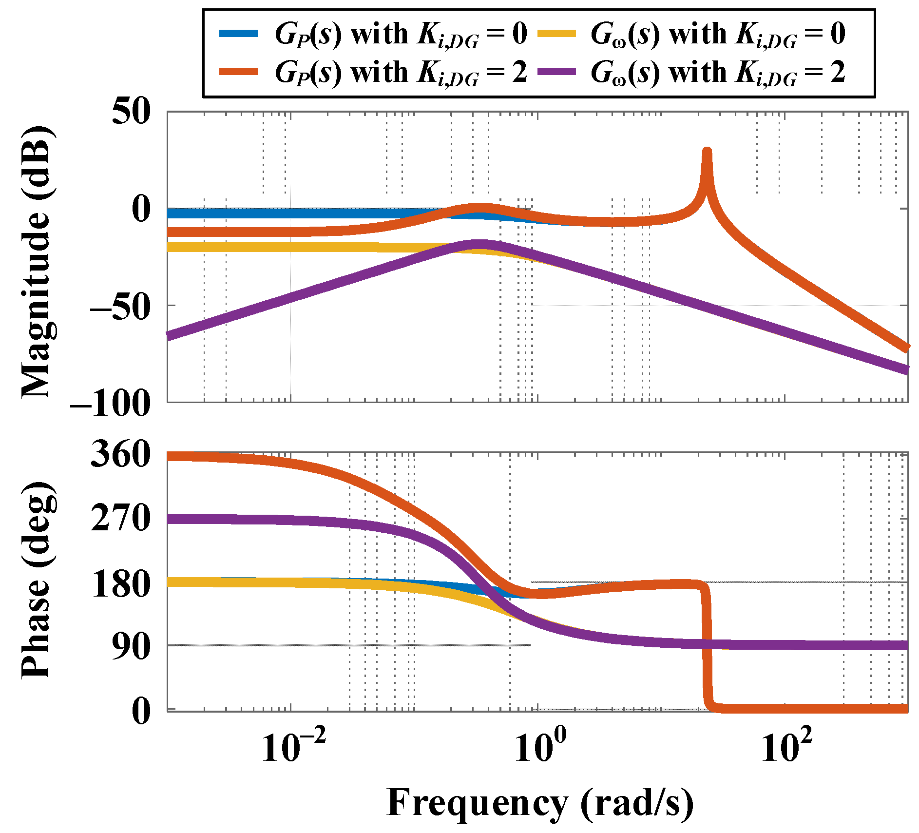
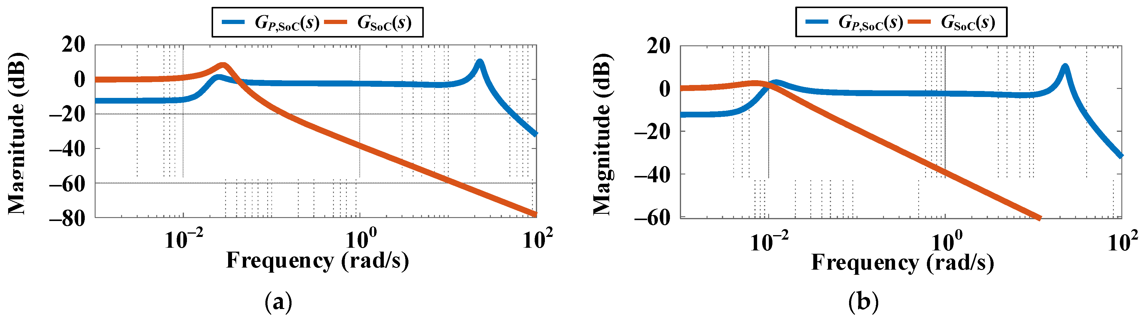
3.3. Frequency-Domain Performance Assessment
3.4. Determination of BESS Energy Recovery Control Loop Parameters by Bandwidth Separation of Control Loops
3.5. State-Space Model
4. Simulation Results and Discussion
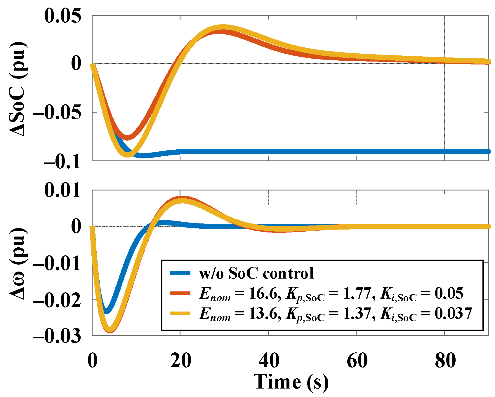
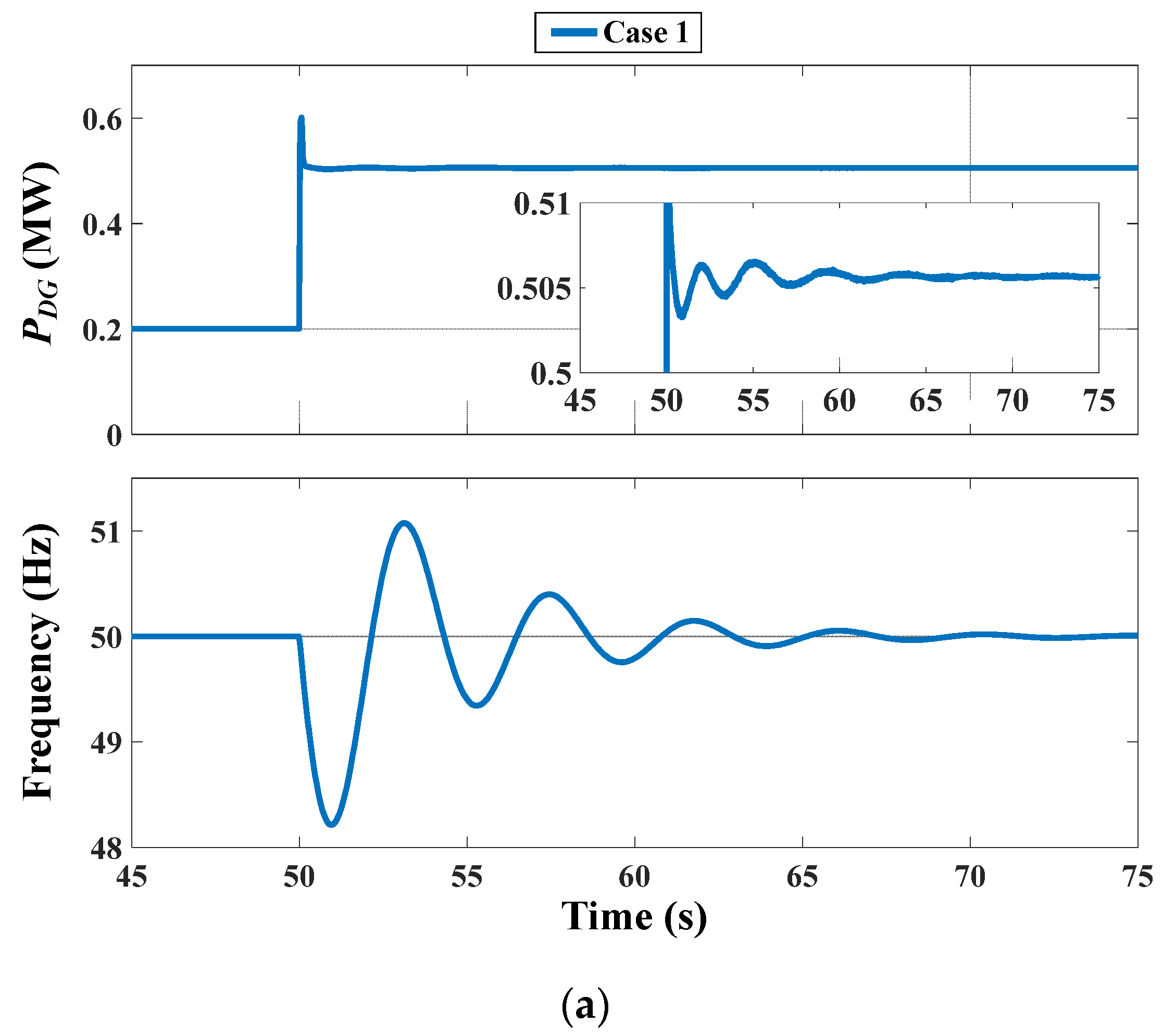
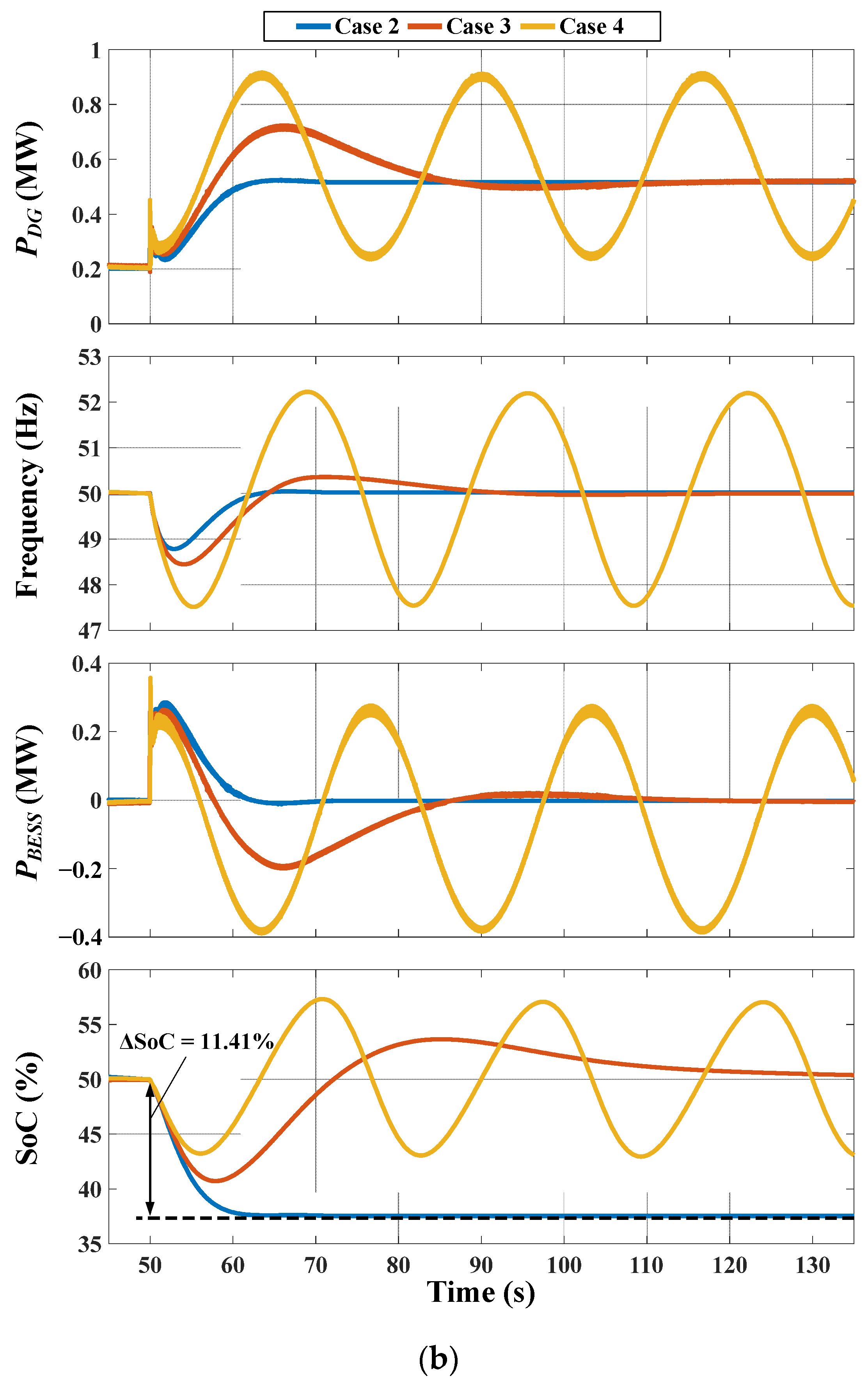
4.1. Analysis of VSG-Based BESS Operation with and without SoC-Level Control
- (1)
- Case 1—operation of the DG without BESS;
- (2)
- Case 2—operation of the DG with BESS and CC-VSG algorithm, but without the energy recovery control;
- (3)
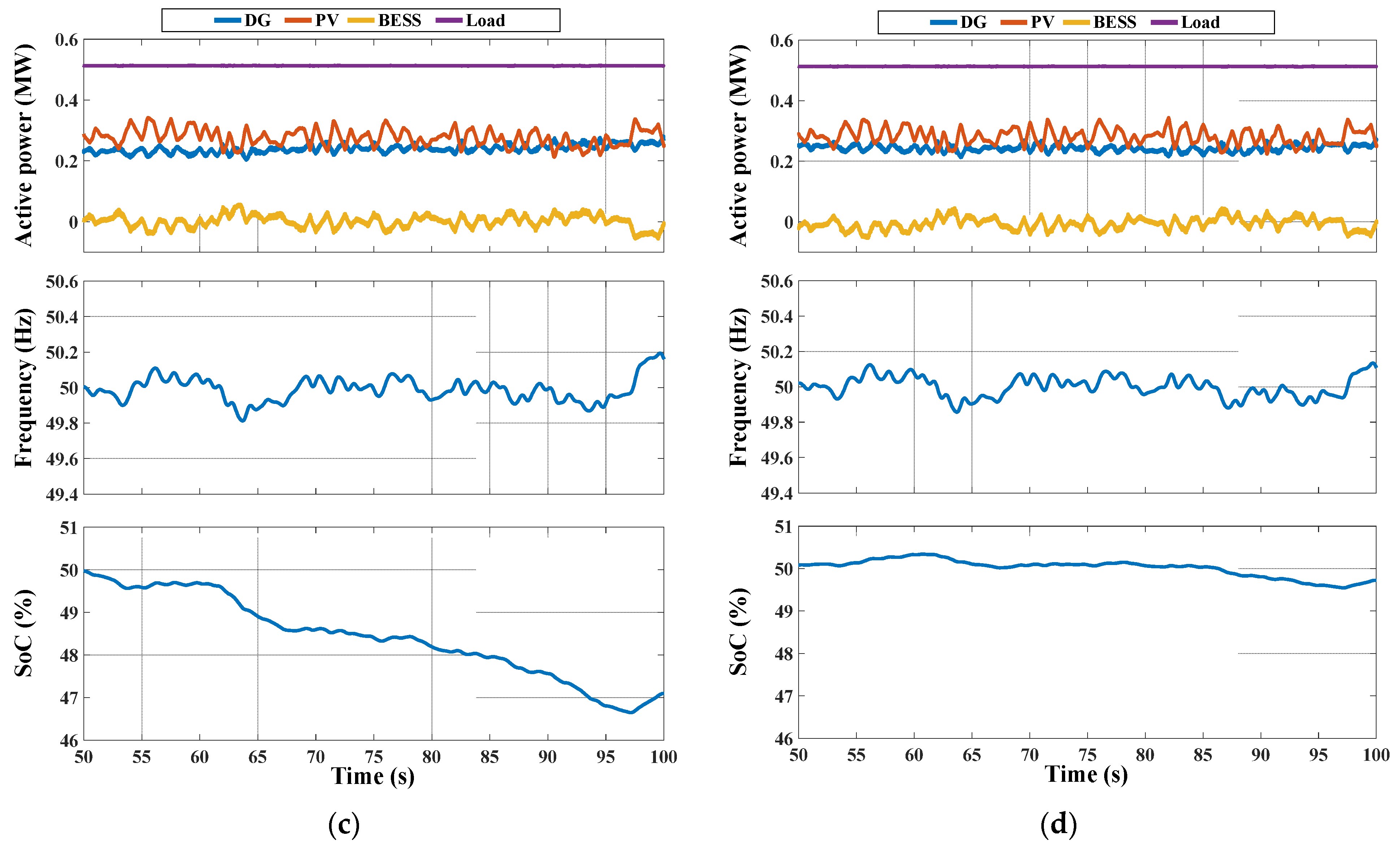
- Case 3—operation of the DG with BESS and CC-VSG algorithm, including the energy recovery control loop, the parameters of which are coordinated with the bandwidth of the secondary frequency control (Table 1);
- (4)
- Case 4—the same as Case 3, but the bandwidth of the energy recovery control loop is increased and equal to the bandwidth of the secondary frequency control (Kp,SoC = 4.07, Ki,SoC = 0.26), while the damping factor for this loop remains the same (ζ ≈ 1).
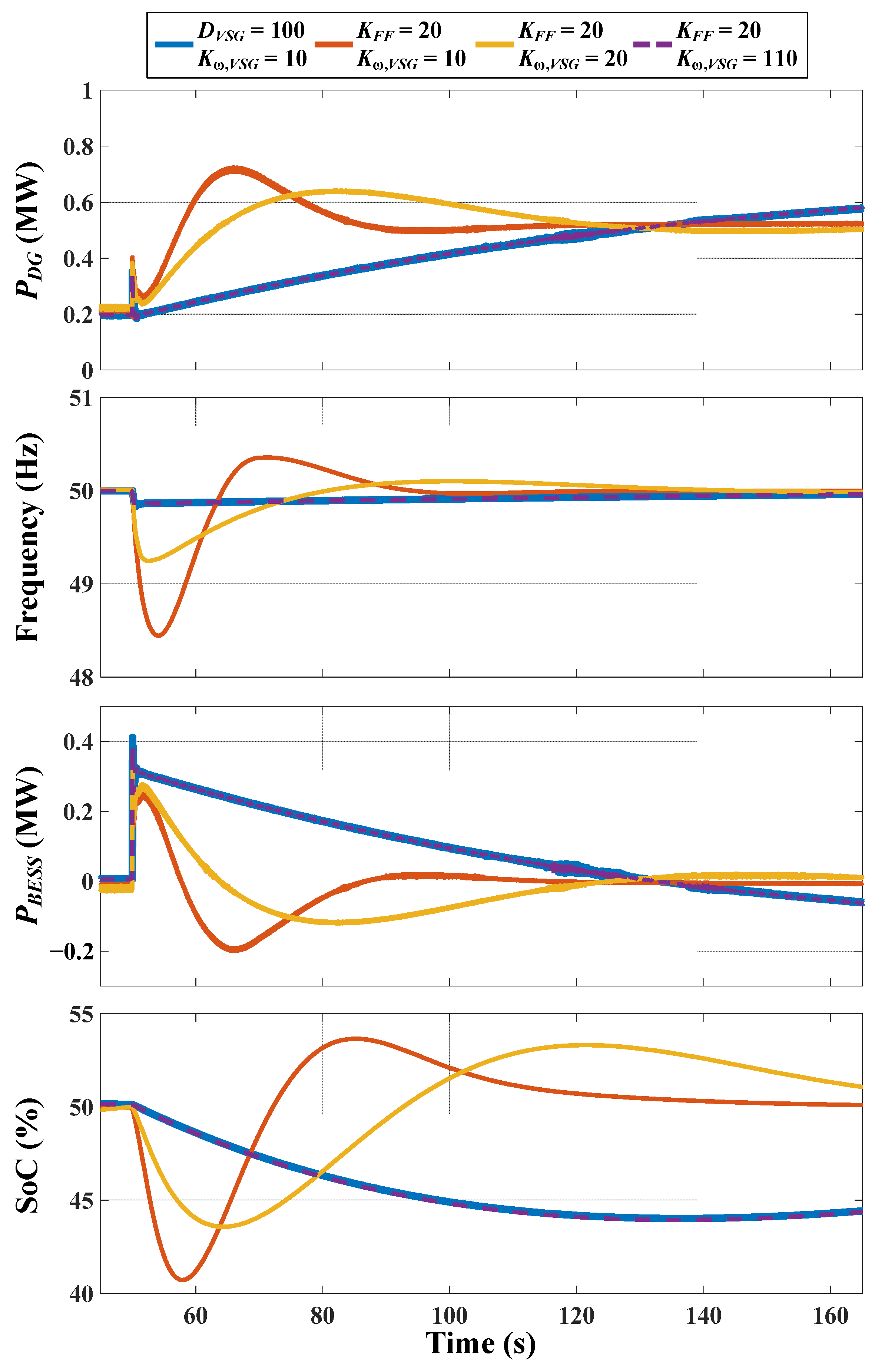
4.2. Analysis of BESS Performance with CC-VSG Algorithm in the Case of Using the Damping Coefficient and the Proposed Feedforward Controller
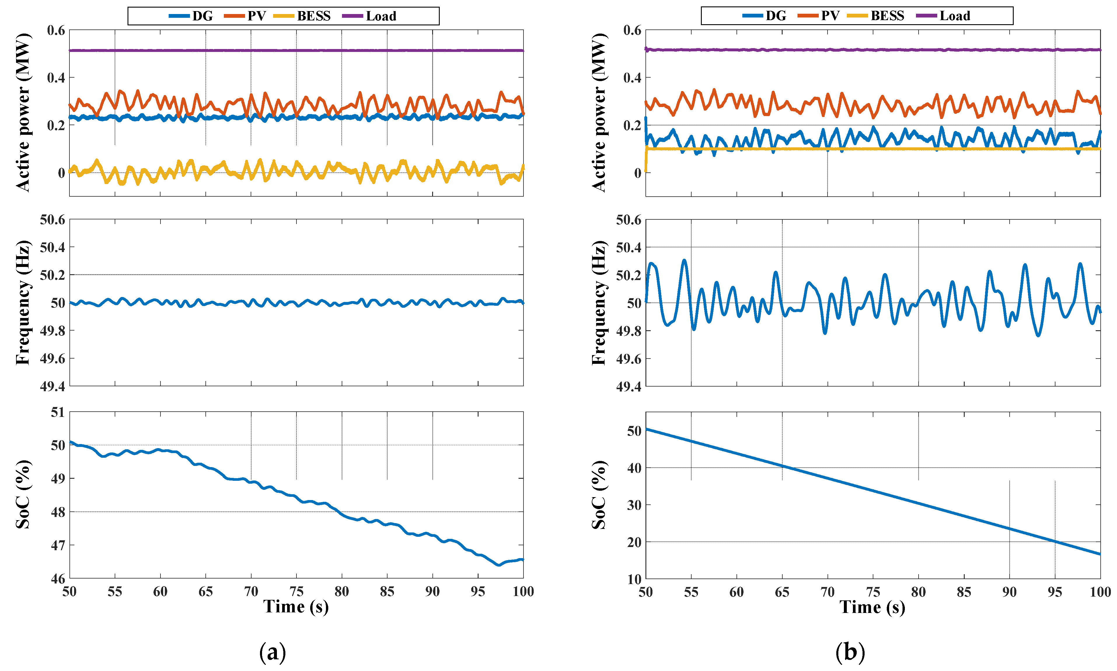
4.3. Analysis of the Microgrid Operation with Variable PV Generation under Different Approaches to BESS Control
5. Conclusions and Prospects
Author Contributions
Funding
Data Availability Statement
Acknowledgments
Conflicts of Interest
Appendix A

| Parameter | Value | Parameter | Value |
|---|---|---|---|
| Snom, MVA | 1 | R1d, X1d, pu | 0.9029, 7.911 |
| Unom, V | 600 | R1q, X1q, pu | 0.05203, 0.3047 |
| fnom, Hz | 50 | uref, ωref, pu | 1 |
| HDG, s | 2.5 | KU, pu | 15 |
| Rs, Xs, pu | 0.01727, 0.07 | Tf, s | 0.3 |
| Xad, Xaq, pu | 2.83, 2.37 | Emax, Emin, pu | 2.1, 0 |
| Rfd, Xfd, pu | 0.006871, 0.5956 | Tmax, Tmin, pu | 1.1, −0.02 |
| Parameter | Value | Parameter | Value |
|---|---|---|---|
| Unom, V | 3.123 | UDC, V | 1500 |
| Qnom, A∙h | 2.761 | fsw, kHz | 4.5 |
| Uexp, V | 3.301 | Kp,CC, pu | 0.052 |
| Qexp, A∙h | 2.592 | Ki,CC, pu∙s | 13.2 |
| Ufull, V | 4.135 | Rv, pu | 0 |
| Qrated, A∙h | 2.998 | Lv, pu | 0.105 |
| R, Ohm | 0.025 | Ku, pu | 1 |
| Parameter | Value | Parameter | Value |
|---|---|---|---|
| Rg1, mOhm | 0.03 | Rs, Ohm | 0.02 |
| Lg1, mH | 0.114 | Rsh, Ohm | 100 |
| Rg2, Ohm | 0.005 | UOC(cell), V | 0.835 |
| Lg2, mH | 0.335 | ISC(cell), A | 2.5 |
| Rg3, Ohm | 0.023 | Ns × Np per module | 36 × 1 |
| Lg3, mH | 0.074 | Ns × Np per array | 22 × 250 |
| Gref, W/m2 | 1000 | UDC, V | 1000 |
| Tref, °C | 25 | fsw, kHz | 8 |
| n | 1.5 | Kp,CC, pu | 1 |
| UG, eV | 1.103 | Ki,CC, pu∙s | 50 |
| IOR, A | 1 × 10⁻⁹ | Kp,PLL, pu | 950 |
| α, A∙K−1 | 0.001 | Ki,PLL, pu∙s | 1900 |
References
- Bhowon, A.; Abo-Al-Ez, K.M.; Adonis, M. Variable-Speed Wind Turbines for Grid Frequency Support: A Systematic Literature Review. Mathematics 2022, 10, 3586. [Google Scholar] [CrossRef]
- Ang, T.-Z.; Salem, M.; Kamarol, M.; Das, H.S.; Nazari, M.A.; Prabaharan, N. A Comprehensive Study of Renewable Energy Sources: Classifications, Challenges and Suggestions. Energy Strategy Rev. 2022, 43, 100939. [Google Scholar] [CrossRef]
- Maatallah, T.; Ghodhbane, N.; Ben Nasrallah, S. Assessment Viability for Hybrid Energy System (PV/Wind/Diesel) with Storage in the Northernmost City in Africa, Bizerte, Tunisia. Renew. Sustain. Energy Rev. 2016, 59, 1639–1652. [Google Scholar] [CrossRef]
- Costa, T.S.; Villalva, M.G. Technical Evaluation of a PV-Diesel Hybrid System with Energy Storage: Case Study in the Tapajós-Arapiuns Extractive Reserve, Amazon, Brazil. Energies 2020, 13, 2969. [Google Scholar] [CrossRef]
- Abusorrah, A.M.; Sepahvand, H. A Frequency/Phase/Amplitude Estimator for Three-Phase Applications Operating at a Low Sampling Rate. Mathematics 2024, 12, 363. [Google Scholar] [CrossRef]
- Deng, X.; Mo, R.; Wang, P.; Chen, J.; Nan, D.; Liu, M. Review of RoCoF Estimation Techniques for Low-Inertia Power Systems. Energies 2023, 16, 3708. [Google Scholar] [CrossRef]
- Farrokhabadi, M.; Canizares, C.A.; Simpson-Porco, J.W.; Nasr, E.; Fan, L.; Mendoza-Araya, P.A.; Tonkoski, R.; Tamrakar, U.; Hatziargyriou, N.; Lagos, D.; et al. Microgrid Stability Definitions, Analysis, and Examples. IEEE Trans. Power Syst. 2020, 35, 13–29. [Google Scholar] [CrossRef]
- Afifi, M.A.; Marei, M.I.; Mohamad, A.M.I. Modelling, Analysis and Performance of a Low Inertia AC-DC Microgrid. Appl. Sci. 2023, 13, 3197. [Google Scholar] [CrossRef]
- Aly, M.; Mohamed, E.A.; Noman, A.M.; Ahmed, E.M.; El-Sousy, F.F.M.; Watanabe, M. Optimized Non-Integer Load Frequency Control Scheme for Interconnected Microgrids in Remote Areas with High Renewable Energy and Electric Vehicle Penetrations. Mathematics 2023, 11, 2080. [Google Scholar] [CrossRef]
- Rosso, R.; Wang, X.; Liserre, M.; Lu, X.; Engelken, S. Grid-Forming Converters: Control Approaches, Grid-Synchronization, and Future Trends—A Review. IEEE Open J. Ind. Appl. 2021, 2, 93–109. [Google Scholar] [CrossRef]
- Baier, C.R.; Melin, P.E.; Torres, M.A.; Ramirez, R.O.; Muñoz, C.; Quinteros, A. Developing and Evaluating the Operating Region of a Grid-Connected Current Source Inverter from Its Mathematical Model. Mathematics 2024, 12, 1775. [Google Scholar] [CrossRef]
- Garzon, O.D.; Nassif, A.B.; Rahmatian, M. Grid Forming Technologies to Improve Rate of Change in Frequency and Frequency Nadir: Analysis-Based Replicated Load Shedding Events. Electronics 2024, 13, 1120. [Google Scholar] [CrossRef]
- Kikusato, H.; Orihara, D.; Hashimoto, J.; Takamatsu, T.; Oozeki, T.; Matsuura, T.; Miyazaki, S.; Hamada, H.; Miyazaki, T. Verification of Power Hardware-in-the-Loop Environment for Testing Grid-Forming Inverter. Energy Rep. 2023, 9, 303–311. [Google Scholar] [CrossRef]
- Anttila, S.; Döhler, J.S.; Oliveira, J.G.; Boström, C. Grid Forming Inverters: A Review of the State of the Art of Key Elements for Microgrid Operation. Energies 2022, 15, 5517. [Google Scholar] [CrossRef]
- Mallemaci, V.; Mandrile, F.; Rubino, S.; Mazza, A.; Carpaneto, E.; Bojoi, R. A Comprehensive Comparison of Virtual Synchronous Generators with Focus on Virtual Inertia and Frequency Regulation. Electr. Power Syst. Res. 2021, 201, 107516. [Google Scholar] [CrossRef]
- Citro, C.; Al-Numay, M.; Siano, P. Extensive Assessment of Virtual Synchronous Generators in Intentional Island Mode. Int. J. Electr. Power Energy Syst. 2024, 157, 109853. [Google Scholar] [CrossRef]
- Hadi Abdulwahid, A.; Al-Razgan, M.; Fakhruldeen, H.F.; Churampi Arellano, M.T.; Mrzljak, V.; Arabi Nowdeh, S.; Moghaddam, M.J.H. Stochastic Multi-Objective Scheduling of a Hybrid System in a Distribution Network Using a Mathematical Optimization Algorithm Considering Generation and Demand Uncertainties. Mathematics 2023, 11, 3962. [Google Scholar] [CrossRef]
- Leng, D.; Polmai, S. Virtual Synchronous Generator Based on Hybrid Energy Storage System for PV Power Fluctuation Mitigation. Appl. Sci. 2019, 9, 5099. [Google Scholar] [CrossRef]
- Mohamed, M.M.; El Zoghby, H.M.; Sharaf, S.M.; Mosa, M.A. Optimal Virtual Synchronous Generator Control of Battery/Supercapacitor Hybrid Energy Storage System for Frequency Response Enhancement of Photovoltaic/Diesel Microgrid. J. Energy Storage 2022, 51, 104317. [Google Scholar] [CrossRef]
- Soni, N.; Doolla, S.; Chandorkar, M.C. Inertia Design Methods for Islanded Microgrids Having Static and Rotating Energy Sources. IEEE Trans. Ind. Appl. 2016, 52, 5165–5174. [Google Scholar] [CrossRef]
- Yuan, C.; Yang, D.; Feng, J.; Liu, C. Constrained Operation Zone of a VSG Considering the DC-side Power Margin. J. Eng. 2019, 2019, 2563–2568. [Google Scholar] [CrossRef]
- Yuan, C.; Liu, C.; Yang, D.; Zhou, R.; Tang, N. Transient Characteristics and Physical Constraints of Grid-Tied Virtual Synchronous Machines. J. Power Electron. 2018, 18, 1111–1126. [Google Scholar] [CrossRef]
- Chen, J.; Liu, M.; Guo, R.; Zhao, N.; Milano, F.; O’Donnell, T. Co-Ordinated Grid Forming Control of AC-Side-Connected Energy Storage Systems for Converter-Interfaced Generation. Int. J. Electr. Power Energy Syst. 2021, 133, 107201. [Google Scholar] [CrossRef]
- Peng, Q.; Fang, J.; Yang, Y.; Liu, T.; Blaabjerg, F. Maximum Virtual Inertia From DC-Link Capacitors Considering System Stability at Voltage Control Timescale. IEEE J. Emerg. Sel. Top. Circuits Syst. 2021, 11, 79–89. [Google Scholar] [CrossRef]
- Xiong, X.; Wu, C.; Hu, B.; Pan, D.; Blaabjerg, F. Transient Damping Method for Improving the Synchronization Stability of Virtual Synchronous Generators. IEEE Trans. Power Electron. 2021, 36, 7820–7831. [Google Scholar] [CrossRef]
- Fang, J.; Tang, Y.; Li, H.; Li, X. A Battery/Ultracapacitor Hybrid Energy Storage System for Implementing the Power Management of Virtual Synchronous Generators. IEEE Trans. Power Electron. 2018, 33, 2820–2824. [Google Scholar] [CrossRef]
- Sarojini, R.K.; Palanisamy, K.; Sanjeevikumar, P.; Nielsen, J.B. Inertia Emulation Control Technique Based Frequency Control of Grid-connected Single-phase Rooftop Photovoltaic System with Battery and Supercapacitor. IET Renew. Power Gener. 2020, 14, 1156–1163. [Google Scholar] [CrossRef]
- Molina, M.G.; Mercado, P.E. Primary Frequency Control of Multi-Machine Power Systems with STATCOM-SMES: A Case Study. Int. J. Electr. Power Energy Syst. 2013, 44, 388–402. [Google Scholar] [CrossRef]
- Ma, Y.; Cao, W.; Yang, L.; Wang, F.; Tolbert, L.M. Virtual Synchronous Generator Control of Full Converter Wind Turbines with Short-Term Energy Storage. IEEE Trans. Ind. Electron. 2017, 64, 8821–8831. [Google Scholar] [CrossRef]
- Shi, M.; Chen, H.; Zhang, C.; Mei, F.; Fang, J.; Miao, H. A Virtual Synchronous Generator System Control Method with Battery SOC Feedback. In Proceedings of the 2018 2nd IEEE Conference on Energy Internet and Energy System Integration (EI2), Beijing, China, 20–22 October 2018; pp. 1–4. [Google Scholar] [CrossRef]
- Delille, G.; Francois, B.; Malarange, G. Dynamic Frequency Control Support by Energy Storage to Reduce the Impact of Wind and Solar Generation on Isolated Power System’s Inertia. IEEE Trans. Sustain. Energy 2012, 3, 931–939. [Google Scholar] [CrossRef]
- Guan, M. Scheduled Power Control and Autonomous Energy Control of Grid-Connected Energy Storage System (ESS) With Virtual Synchronous Generator and Primary Frequency Regulation Capabilities. IEEE Trans. Power Syst. 2022, 37, 942–954. [Google Scholar] [CrossRef]
- Hu, C.; Zhang, X.; Liu, F.; Shi, R.; Xu, H.; Cao, R. An SOC Based Control Strategy for VSG Using Weight Coefficient in Grid Connected Mode. In Proceedings of the 2016 IEEE 8th International Power Electronics and Motion Control Conference (IPEMC-ECCE Asia), Hefei, China, 22–26 May 2016; pp. 1743–1746. [Google Scholar] [CrossRef]
- Shim, J.W.; Verbic, G.; Zhang, N.; Hur, K. Harmonious Integration of Faster-Acting Energy Storage Systems Into Frequency Control Reserves in Power Grid With High Renewable Generation. IEEE Trans. Power Syst. 2018, 33, 6193–6205. [Google Scholar] [CrossRef]
- Qi, N.; Fang, W.; Wang, W.; Liu, X.; Liu, S. SoC Balancing Method for Energy Storage Systems in DC Microgrids Using Simplified Droop Control. J. Power Electron. 2021, 21, 1200–1212. [Google Scholar] [CrossRef]
- Meng, T.; Lin, Z.; Wan, Y.; Shamash, Y.A. State-of-Charge Balancing for Battery Energy Storage Systems in DC Microgrids by Distributed Adaptive Power Distribution. IEEE Control Syst. Lett. 2022, 6, 512–517. [Google Scholar] [CrossRef]
- Zhi, N.; Ding, K.; Du, L.; Zhang, H. An SOC-Based Virtual DC Machine Control for Distributed Storage Systems in DC Microgrids. IEEE Trans. Energy Convers. 2020, 35, 1411–1420. [Google Scholar] [CrossRef]
- Chen, J.; Liu, M.; Milano, F.; O’Donnell, T. Adaptive Virtual Synchronous Generator Considering Converter and Storage Capacity Limits. CSEE J. Power Energy Syst. 2022, 8, 580–590. [Google Scholar] [CrossRef]
- Huang, Y.; Lv, Q.; Zhang, Z.; Dong, H. Virtual Synchronous Generator Adaptive Control of Energy Storage Power Station Based on Physical Constraints. Energy Eng. 2023, 120, 1401–1420. [Google Scholar] [CrossRef]
- Zhang, X.; Li, D.; Yang, Z.; Tian, L.; Meng, J.; Liu, Y.; Fu, C. Fuzzy Adaptive Virtual Inertia Control of Energy Storage Systems Considering SOC Constraints. Energy Rep. 2023, 9, 2431–2439. [Google Scholar] [CrossRef]
- Huang, Y.; Lv, Q.; Zhang, Z.; Dong, H. Fuzzy Adaptive Control of Virtual Synchronous Generator Based on Constraints of Discharge Characteristics of Energy Storage Batteries. In Proceedings of the 2022 3rd International Conference on Advanced Electrical and Energy Systems (AEES), Lanzhou, China, 23–25 September 2022; IEEE: New York, NY, USA; pp. 373–378. [Google Scholar] [CrossRef]
- Shim, J.W.; Verbic, G.; An, K.; Lee, J.H.; Hur, K. Decentralized Operation of Multiple Energy Storage Systems: SOC Management for Frequency Regulation. In Proceedings of the2016 IEEE International Conference on Power System Technology (POWERCON), Wollongong, NSW, Australia, 28 September–1 October 2016; IEEE: New York, NY, USA; pp. 1–5. [Google Scholar] [CrossRef]
- Suvorov, A.; Askarov, A.; Bay, Y.; Ufa, R. Freely Customized Virtual Generator Model for Grid-Forming Converter with Hydrogen Energy Storage. Int. J. Hydrogen Energy 2022, 47, 34739–34761. [Google Scholar] [CrossRef]
- Mandrile, F.; Carpaneto, E.; Bojoi, R. Grid-Feeding Inverter with Simplified Virtual Synchronous Compensator Providing Grid Services and Grid Support. IEEE Trans. Ind. Appl. 2021, 57, 559–569. [Google Scholar] [CrossRef]
- Suvorov, A.; Askarov, A.; Kievets, A. A Freely Configurable Structure of Virtual Synchronous Generator for Grid-Forming Converters. Electr. Eng. 2023, 105, 1331–1345. [Google Scholar] [CrossRef]
- Suvorov, A.; Askarov, A.; Bay, Y.; Maliuta, B.; Achitaev, A.; Suslov, K. Comparative Small-Signal Stability Analysis of Voltage-Controlled and Enhanced Current-Controlled Virtual Synchronous Generators under Weak and Stiff Grid Conditions. Int. J. Electr. Power Energy Syst. 2023, 147, 108891. [Google Scholar] [CrossRef]
- Suvorov, A.; Askarov, A.; Ruban, N.; Rudnik, V.; Radko, P.; Achitaev, A.; Suslov, K. An Adaptive Inertia and Damping Control Strategy Based on Enhanced Virtual Synchronous Generator Model. Mathematics 2023, 11, 3938. [Google Scholar] [CrossRef]
- Rico-Azagra, J.; Gil-Martínez, M. Feedforward of Measurable Disturbances to Improve Multi-Input Feedback Control. Mathematics 2021, 9, 2114. [Google Scholar] [CrossRef]
- Askarov, A.; Ruban, N.; Bay, Y.; Ufa, R.; Malkova, Y.; Suvorov, A. A Feedforward Control for Increasing the Damping Effect of Enhanced Current-Controlled Virtual Synchronous Generator. Electr. Power Syst. Res. 2024, 234, 110659. [Google Scholar] [CrossRef]
- Chen, M.; Zhou, D.; Wu, C.; Blaabjerg, F. Characteristics of Parallel Inverters Applying Virtual Synchronous Generator Control. IEEE Trans. Smart Grid 2021, 12, 4690–4701. [Google Scholar] [CrossRef]
- Meegahapola, L.; Bu, S.; Gu, M. Hybrid AC/DC Power Grids: Stability and Control Aspects; Power Systems; Springer International Publishing: Cham, Switzerland, 2022. [Google Scholar] [CrossRef]
- Kundur, P.S. Power System Stability. In Power System Stability and Control; CRC Press: Boca Raton, FL, USA, 2012. [Google Scholar]
- Vega-Herrera, J.; Rahmann, C.; Valencia, F.; Strunz, K. Analysis and Application of Quasi-Static and Dynamic Phasor Calculus for Stability Assessment of Integrated Power Electric and Electronic Systems. IEEE Trans. Power Syst. 2021, 36, 1750–1760. [Google Scholar] [CrossRef]
- Du, Y.; Lu, X.; Wang, X. Chapter Eight-Power System Operation with Power Electronic Inverter–Dominated Microgrids. In New Technologies for Power System Operation and Analysis; Jiang, H., Zhang, Y., Muljadi, E., Eds.; Academic Press: Cambridge, MA, USA, 2021; pp. 259–274. [Google Scholar] [CrossRef]
- Meng, L.; Zafar, J.; Khadem, S.K.; Collinson, A.; Murchie, K.C.; Coffele, F.; Burt, G.M. Fast Frequency Response from Energy Storage Systems—A Review of Grid Standards, Projects and Technical Issues. IEEE Trans. Smart Grid 2020, 11, 1566–1581. [Google Scholar] [CrossRef]
- Fan, L. Control and Dynamics in Power Systems and Microgrids; CRC Press: Boca Raton, FL, USA, 2017. [Google Scholar] [CrossRef]
- Liu, H.; Sun, C.; Zhang, X.; Wang, N.; Wang, J. Design of Energy Recovery Control for General Virtual Synchronous Machines Based on Various Forms of Energy Storage. Appl. Sci. 2023, 13, 8059. [Google Scholar] [CrossRef]
- Dorf, R.; Bishop, R. Modern Control Systems, 13th ed.; Pearson: Hoboken, NJ, USA, 2016. [Google Scholar]
- Dini, P.; Colicelli, A.; Saponara, S. Review on Modeling and SOC/SOH Estimation of Batteries for Automotive Applications. Batteries 2024, 10, 34. [Google Scholar] [CrossRef]
- Ul Hassan, M.; Saha, S.; Haque, M.E.; Islam, S.; Mahmud, A.; Mendis, N. A Comprehensive Review of Battery State of Charge Estimation Techniques. Sustain. Energy Technol. Assess. 2022, 54, 102801. [Google Scholar] [CrossRef]
- Shen, P.; Ouyang, M.; Han, X.; Feng, X.; Lu, L.; Li, J. Error Analysis of the Model-Based State-of-Charge Observer for Lithium-Ion Batteries. IEEE Trans. Veh. Technol. 2018, 67, 8055–8064. [Google Scholar] [CrossRef]
- Sun, C.; Joos, G.; Ali, S.Q.; Paquin, J.N.; Rangel, C.M.; Al Jajeh, F.; Novickij, I.; Bouffard, F. Design and real-time implementation of a centralized microgrid control system with rule-based dispatch and seamless transition function. IEEE Trans. Ind. Appl. 2020, 56, 3168–3177. [Google Scholar] [CrossRef]


| Parameter | Value | Parameter | Value |
|---|---|---|---|
| fb, Hz | 50 | Kω,DG, pu | 0 |
| Cf, pu | 0.112 | HVSG, s | 5 |
| Lv, pu | 0.105 | DVSG, pu | 0 |
| Lg1, pu | 0.155 | Kω,VSG, pu | 10 |
| Lg2, pu | 0.05 | KFF, pu | 20 |
| HDG, s | 2.5 | Enom, pu∙s | 16.6 |
| DDG, pu | 0 | Ki,SoC, pu∙s | 0.05 |
| TDG, s | 1 | Kp,SoC, pu | 1.77 |
| Ki,DG, pu∙s | 2 | SoCref, pu | 0.5 |
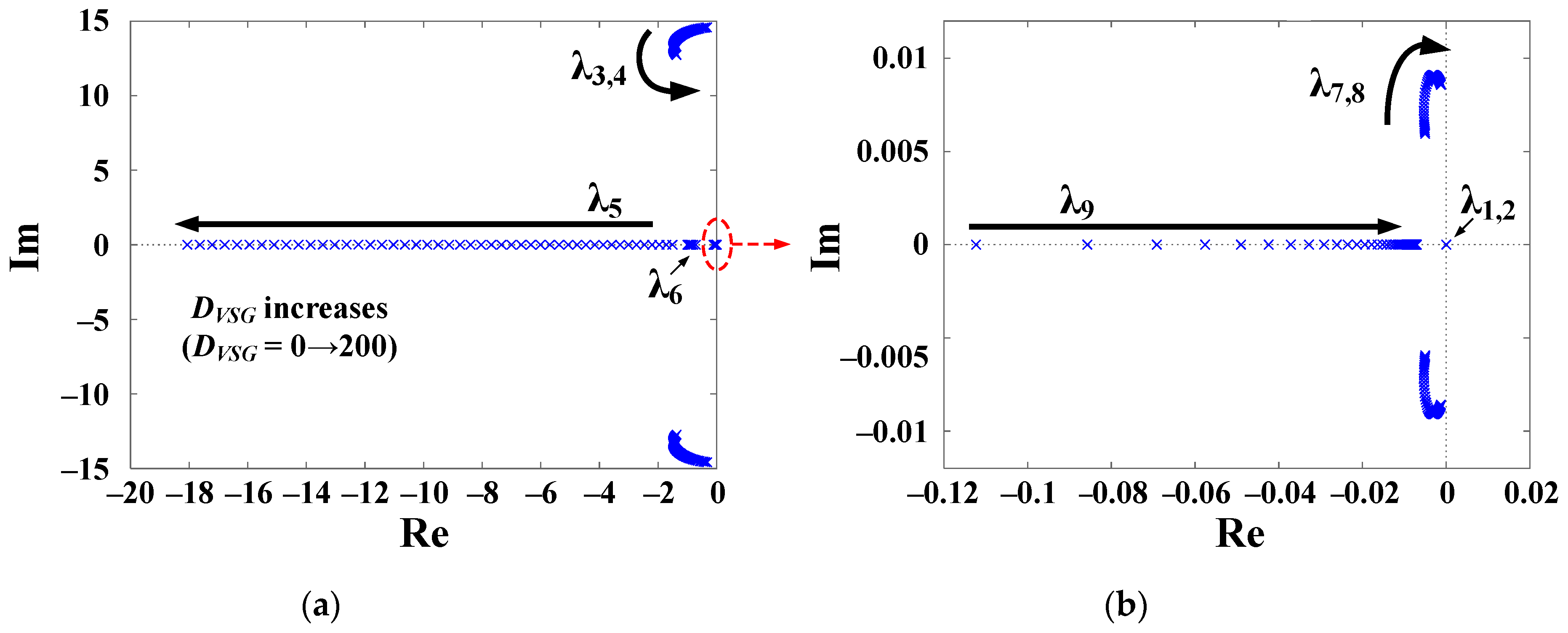
| ωn, Hz | Sensitivity of λ to DVSG | Sensitivity of λ to KFF | Mainly Related State Variable | |
|---|---|---|---|---|
| λ3,4 | ≈2.3 | −0.016 ∓ j0.015 | −0.113 ∓ j0.024 | ΔωDG, ΔωVSG, Δδ |
| λ7,8 | <0.05 | 0.021 ∓ j0.021 | 0 | βSoC, ΔSoC |
Disclaimer/Publisher’s Note: The statements, opinions and data contained in all publications are solely those of the individual author(s) and contributor(s) and not of MDPI and/or the editor(s). MDPI and/or the editor(s) disclaim responsibility for any injury to people or property resulting from any ideas, methods, instructions or products referred to in the content. |
© 2024 by the authors. Licensee MDPI, Basel, Switzerland. This article is an open access article distributed under the terms and conditions of the Creative Commons Attribution (CC BY) license (https://creativecommons.org/licenses/by/4.0/).
Share and Cite
Askarov, A.; Rudnik, V.; Ruban, N.; Radko, P.; Ilyushin, P.; Suvorov, A. Enhanced Virtual Synchronous Generator with Angular Frequency Deviation Feedforward and Energy Recovery Control for Energy Storage System. Mathematics 2024, 12, 2691. https://doi.org/10.3390/math12172691
Askarov A, Rudnik V, Ruban N, Radko P, Ilyushin P, Suvorov A. Enhanced Virtual Synchronous Generator with Angular Frequency Deviation Feedforward and Energy Recovery Control for Energy Storage System. Mathematics. 2024; 12(17):2691. https://doi.org/10.3390/math12172691
Chicago/Turabian StyleAskarov, Alisher, Vladimir Rudnik, Nikolay Ruban, Pavel Radko, Pavel Ilyushin, and Aleksey Suvorov. 2024. "Enhanced Virtual Synchronous Generator with Angular Frequency Deviation Feedforward and Energy Recovery Control for Energy Storage System" Mathematics 12, no. 17: 2691. https://doi.org/10.3390/math12172691