1. Introduction
The use of dynamic chaos phenomena for the creation and operation of secure data transmission systems can be identified as a special area of theoretical and applied research since the last decade of the 20th century. There are a big number of significant publications on this topic in the world literature, including the definitive research of Lorenz, Rössler [
1], Anishchenko [
2,
3], Pecora [
4], Chua [
5], Leonov and Kuznetsov [
6], and other researchers [
7,
8,
9,
10], which show the use of chaotic systems as carrier oscillation generators for communication channels. Chaotic generators, in contrast to the van der Pol generator of regular oscillations widely used in communication channels, are commonly called nonlinear dynamic systems that, with certain combinations of their parameters, go into the mode of generating chaotic oscillations with the formation of so-called “strange” attractors in their phase space [
1,
6,
11], including recently discovered “hidden” attractors [
6,
12]. There is a huge number of publications, starting with the works of Lorenz, Roesler, etc. [
1,
11], in which models of this kind of nonlinear dynamic systems are identified and studied, which provides a rich selection of chaotic generators models when creating secure data transmission systems with a chaotic carrier. When forming such systems, various methods can be used [
7,
10,
13] both for:
- (i)
Introducing useful information into a chaotic carrier (masking with chaotic oscillations [
7], modulating the parameters of a chaotic generator by additive or multiplicative injection of a useful signal [
9], Runge–Kutta method modulation [
14], mixing, nonlinear mixing, shift keying, additive mixing, etc. [
7]) on the transmitter side;
- (ii)
Restoring or recover/decoding the information component of the transmitted signal on the receiver side (most of them are chaotic carrier filtering, estimation of the least squares method (LS method), and adaptive methods including chaotic synchronization, and the use of state observers). Chaotic carrier filtering [
7] may apply only to low security methods of masking; LS method [
2] mainly provides great error of signal recovering for nonlinear systems [
15] so the probable good practice methods are the adaptive ones.
Along with continuous chaotic systems, discrete-form chaotic systems are also used for secure transmission of data and images, which in some cases can facilitate their physical hardware implementation. Modern methods, allowing to work with such systems, may include but are not limited to various types of construction of chaotic maps and chaotic masking and modulation. For example, in [
16,
17], variants of two-dimensional and one-dimensional chaotic maps for discrete chaotic systems are presented, including issues of their realization on field-programmable gate arrays (FPGAs). In [
18,
19], the issues in the construction of chaotic maps for discrete chaotic systems for secure image transmission, as well as their encryption using models of high-order chaotic systems and chaotic maps of various kinds [
20,
21,
22,
23], are considered.
In continuous chaotic systems, chaotic synchronization [
8] refers now to the most popular principle of both restoring a useful signal and forming the structure of a data transmission system with a chaotic carrier as a whole due to the possibility of practical implementation.
There are different methods and approaches to chaotic system synchronization: backstepping [
24], sliding mode control (SMC) [
25], forced SMC with an analytical design of aggregated regulators (ADARs) method [
26], robust methods [
27], indirect coupled synchronization [
28], and others.
An alternative to chaotic synchronization may be a method of restoring the useful signal on the receiving side using state observers [
29]. Interest in research in this area [
9] may be that the use of well-known state observers (the well-known Luenberger observer and the Kalman filter [
30]) is limited by essentially nonlinear systems, the models of which are chaotic generators.
The state-of-the-art state observer technologies used in the development of chaotic carrier communication systems include unknown input observer synchronization [
29,
31], adaptive unknown-input observer [
32], descriptor observer [
33], high gain observer synchronization [
34], robust chaotic observer [
35], chaotic synchronization and communication via linear-state observer design [
36], and other observed-based methods for secure communication [
13,
37,
38,
39], but most of these observers have some limitations for direct application to nonlinear systems. Nonlinear system unknown variables’ recovery may be provided by a nonlinear synergetic observer based on the ADAR method of the synergetic control theory (SCT).
ADAR and SCT were developed by the scientific school of Professor A.A. Kolesnikov of the Southern Federal University [
40,
41]. SCT is partially based on Synergetics general principles formulated by H. Haken. Within the framework of this technique, the problems of synthesizing state observers for single- and multi-channel data transmission systems with a chaotic carrier were explored in our previous publications [
15,
42,
43]. These results may be used to create secure data transmission systems based on various chaotic generators of the second and third order.
In this paper, we explore the issues of practical implementation of results that have been achieved in our previous manuscripts [
42,
44]. A procedure is presented for the analytical synthesis of a single-channel synergetic state observer based on the Genesio–Tesi chaotic generator [
11]. The system model was implemented in MATLAB/Simulink R2022a (The MathWorks, Inc., Natick, MA, USA) based on the model-based design [
45] approach to modeling. Software implementation of the system was completed and ready for transfer and further implementation on Raspberry Pi (Raspberry Pi Foundation, Pencoed, UK) single-board computers, as well as a part of various cyber-physical systems [
46].
The main contributions of this study are summarized as follows:
We firstly present, in detail, a mathematical procedure for modeling a single-channel synergetic state observer for a third-order nonlinear chaotic system.
The procedure is realized on the example of a chaotic Genesio–Teri generator with generator model parameter multiplicative modulation of the useful signal on the transmitter side.
An example of realization of chaotic system on the basis of Genesio–Teri generator and synergetic state observer in MATLAB/Simulink R2022a (The MathWorks, Inc., Natick, MA, USA) environment is provided.
Experimental realization of the obtained system on a single-board computer Raspberri Pi to demonstrate the fundamental possibility of physical implementation of the system of secure data transmission on the above principles for certain areas of application.
Thus, the aim of the manuscript is to demonstrate in detail an analytical modeling procedure for a nonlinear state observer for building a single-channel data transmission system with a chaotic carrier for a Genesio–Tesi chaotic generator as well as to provide some examples of practical application and implementation.
The rest of this paper is organized as follows: In
Section 2, a description of the mathematical model of a Genesio–Tesi third-order chaotic generator is given, which is chosen as a generator of chaotic carrier oscillations in this work. The selected system structure and coding (chaotic mixing) and decoding (signal recovery) technologies are described, with a brief overview of synergetic state observers given as well as target hardware platform and received signal decoding/restore issues are discussed.
Section 3 describes the modeling sequence (analytical form design procedure) of a synergetic state observer for a Genesio–Tesi chaotic generator with resulting system simulation, as well as MATLAB/Simulink R2022a (The MathWorks, Inc., Natick, MA, USA) and stand-alone software implementation for PC and Raspberry Pi (Raspberry Pi Foundation, Pencoed, UK) platforms.
Section 4 concludes the paper.
2. Materials and Methods
This paper sets the task of building a system of hidden information transmission using the phenomena of dynamic chaos. In the developed system, data securing will be provided by means of masking the chaotic carrier of the selected chaos generator model. The signal recovery will be performed using a single-channel synergetic state observer.
The modeling procedure of the synergetic state observer is performed in symbolic form by virtue of the given nonlinear mathematical model of the dynamic system. Thus, the algorithm and the general procedure depend on the dimensionality of the system and the structure of the right parts of the system of differential equations, the number and location of unobservable variables. These differences require making some (although finite in the number of possible variants) decisions in the general modeling process, which leads to the need to develop a unique procedure for virtually every nonlinear model of the chaotic oscillator used. These procedures are the novelty and build up a scientific value of this and other our related works. In addition, in some cases, the modeling procedure may not result in a performable observer since the modulation of some coefficients may adversely affect the overall stability of the system, which requires additional study and research.
2.1. Chaotic Generator Model
As the modeling procedure is chaotic generator model dependent, and we have been presented synergetic observer design procedures for some famous chaotic generator in our previous works (e.g., Lorenz, Rössler, Shimizu–Morioka, etc. [
15,
41,
42,
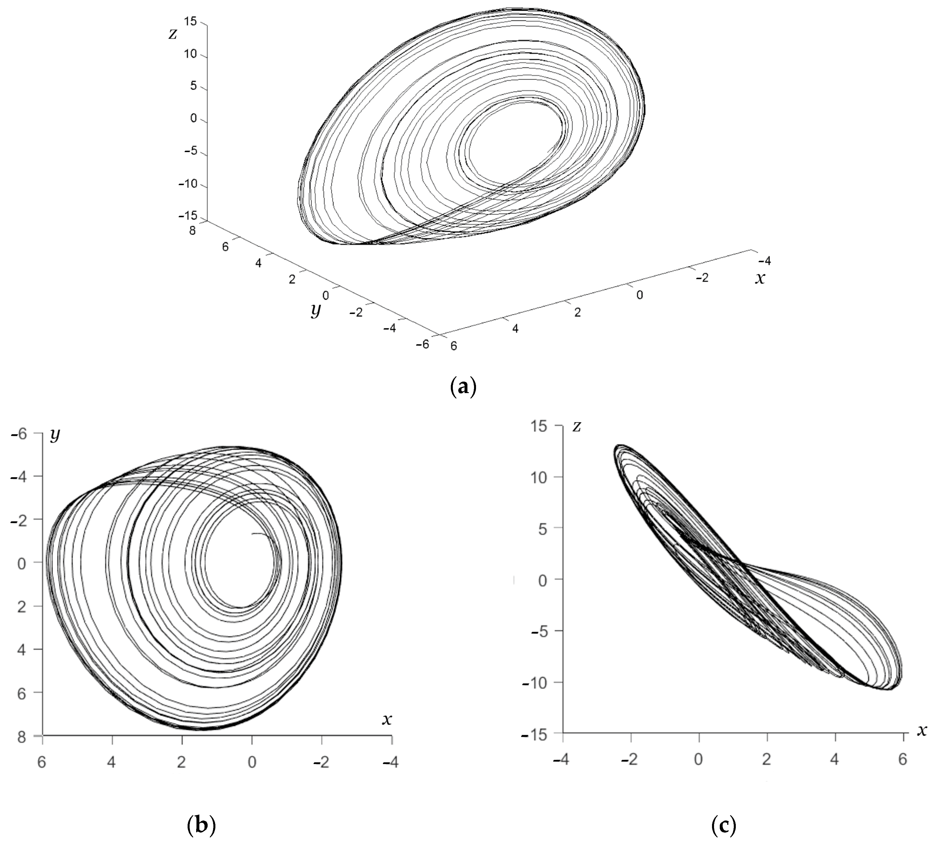
43]), here we consider Genesio–Tesi chaotic system mathematical model [
11] as a chaotic carrier generator component:
where
are system dynamic (or state) variables,
are system constant parameters, and
t is the time. The phase portrait along with its projections is shown in
Figure 1.
The canonical form of the mathematical model of a third-order chaotic generator for single-channel transmission [
2,
3] is:
where
are the system state variables,
t is the time, and
k is the vector of constant coefficients.
This form allows us to collect all the significant information about the parameters in the value of one system variable, which ensures masking of the chaotic carrier and transmission of all necessary information over only a single channel.
If we apply another mathematical model of a chaotic generator of the third order that does not correspond to the canonical form of Equation (2) (a fairly common case), to bring it to the canonical form of Equation (2), it is necessary to apply the procedure for reconstructing a dynamic system by the method of sequential differentiation [
3].
Since the original system of Equation (1) has the form for which the global reconstruction synthesis procedure [
3] is not required to obtain its one-dimensional implementation by Equation (2), we may just proceed to the direct synthesis of the synergetic observer.
2.2. Transmitter Side Useful Signal Modulation Method
From a number of different methods of chaotic signal substitution mentioned in the previous section, for this work we choose chaos modulation by nonlinear substitution of a useful signal into the structure of the mathematical model. For this purpose, we choose a constant coefficient in the chaotic oscillator model by Equation (1) as an unobservable parameter, which will be the carrier of the useful signal.
In this case, the modulating term must be chosen so that it enters the mathematical model multiplicatively rather than additively; otherwise, the useful signal can be extracted from the transmitted one by filtering, which was shown by Short in [
47]. Moreover, the security issue of chaotic masking with additive modulation was also demonstrated in [
48]. Results of [
47,
48] mean that more simple masking techniques [
10] a priori provide more weak protection overall or at disclosing some information about implemented modulation methods and should not be considered.
We explore short message transmission in order to maintain the steganographic property, which is an advantage of the chaotic carrier system, that may disappear for long message transmission. In [
47,
48] and our previous study [
15,
44] it is shown that despite chaotic carrier signal added additively to a chaotic oscillator model is amenable to extraction by filtering [
47], in our work [
15,
44] when multiplicative mixing is used, it is still possible to detect periodic (non-chaotic sequences) in the communication channel when analyzed in detail using fast Fourier transform (FFT) of the signal. When transmitting long messages, such detection will be some noticeable, and when transmitting short messages, the possibility of their detection against the background of noise and other interference is reduced, which increases the steganographic property of the system. In general, there are no fundamental restrictions on the transmission of long and even streaming messages, but here we should take into account the computational delay due to the work of the observer in the restoration of the signal on the receiver side.
According to the above-mentioned considerations, as an unobserved parameter in Equation (1), we take the parameter
a. We introduce a new parameter
a*(
t) for the Genesio–Tesi generator instead of
a constant:
where
is a useful signal to be transmitted via secure communication channel. We then take the signal
, generated by the system of Equation (1), as the basis for the transmission, which will be transmitted over an open communication channel, under the following assumptions:
The communication channel is used to transmit digital information, in this case the modulating signal is piecewise constant;
Modulated parameter .
From [
11], it is known that the system acquires chaotic properties when
, i.e., such a set of parameters ensures the generation of chaotic oscillations for the system under consideration. To restore a useful signal nonlinearly masked by chaotic oscillations, below we construct an observer for the system of Equation (1), which will estimate the parameter
on the receiver side.
2.3. Receiver Side Signal Reconstruction Method
As a data signal recovery mechanism on the receiver side, we will use the synergetic state observer. The state observer allows you to continuously receive information from the plant regarding changes in the control action and/or control value.
These algorithms are nonlinear feedbacks, guaranteeing a regular or chaotic mode appearing. The method consists in introducing invariant manifolds to reduce the geo-metric dimension and stage-by-stage decomposition of the original system. This theory, method, and procedure were developed based on the ADAR method [
42,
43]. Using a synergetic observer eliminates any other command links or synchronization mechanisms mandatory for the data recovery methods, including chaotic synchronization.
In a synergetic nonlinear observer, the final structure of the observer contains the right parts of the original observation object differential equations, in our case the nonlinear Genesio–Tesi system used as a generator of carrier chaotic oscillations. As a result, the structure of the observer changes depending on the chosen chaotic generator, which increases the security of the developed system for hidden information transmission, while all terms of the original system are taken into account. But due to this reason, the modeling of the synergetic observer should be considered each time as a separate design problem, because the procedure generally depends on the selected chaotic mathematical model of the system, its dimension, and its structure.
2.4. Secured Data Transmission System Block Diagramm
The block diagram of the system is presented in
Figure 2. An information signal is received at the input of the system, which is then multiplicatively masked in the transmitter by a chaotic signal produced by a chaotic generator. In a communication channel, noise is mixed into the received complex signal. Thus, a mixed signal is obtained, which is then sent to the receiver unit. In the receiver, the signal is restored, and the reconstruction error is visible on the simulation results, that is, how accurately the useful signal is restored from that received in the communication channel and the restored signal itself.
2.5. Target Hardware Platforms
Initial analytical modeling of the state observer and initial simulation were performed in the Maple 6 (Waterloo Maple Inc., Waterloo, ON, Canada) symbolic computing environment software. The following hardware and software tools and platforms are assumed to be used for more detailed computer simulation: First is a typical PC with Intel Core i5 10505, 3.2 GHz, RAM: 8 GB DDR, ROM: SSD 256 GB, Intel UHD Graphics 630 (DELL Optiplex 7780, DELL Inc., Round Rock, TX, USA) under MS Windows 10 (Microsoft Corp., Redmond, TX, USA) with MATLAB/Simulink R2022a (The MathWorks, Inc., Natick, MA, USA) numerical simulation software to build a simulation model of the transmitter, receiver, and communication channel with Simulink blocks in the MATLAB environment. This will allow us to verify the results of symbolic modeling in Maple 6 (Waterloo Maple Inc., Waterloo, ON, Canada), as well as to create a simulation model of any complexity, including sub-models of communication channels, external influences, etc. The visual design interface makes this tool convenient and intuitive to adapt the presented results to specific requirements and conditions. Additionally, the feature of automatic generation of C/C++ code from Simulink block-models within the framework of a model-based design approach allows realizing stand-alone applications reflecting Simulink block diagrams with minimal efforts.
The second is a single-board Raspberry Pi 4B (Raspberry Pi Foundation, Pencoed, UK) computer used as an example of a single-purpose industrial controller providing transmitter and/or receiver hardware platform simulation [
49]. This platform can sufficiently simulate real encryption or decryption devices on the transmitter and receiver sides or components of the target cyber-physical system. The presence of a standard Linux-based operating system allows creating a universal software implementation of the system components and actually simulates the operation of the system layout in the field.
2.6. Transmission and Recovery Error Detection/Correction
The used method of elimination of transmission and recovery errors of binary data is repeated/multiple transmission. Special methods of error detection and correction were not applied within the framework of this work; their selection and application to data transmitted over chaotic carrier systems requires further study and discussion, and since at this stage it is not the main problem, to demonstrate the fundamental feasibility of the method we have been using: the method of multiple transmission with statistical selection of the most frequently repeated variant. The disadvantage of the method is the need for redundant multiple transmissions, but due to its unambiguity, it gives significant results, which can serve as initial data for studying the applicability of other known methods of error detection and correction.
3. Results and Discussion
3.1. Modeling Procedure of Synergetic State Observer for Genesio–Tesi Chaotic Generator
For further work, the Genesio–Tesi chaotic generator model by Equation (1) was chosen.
In accordance with the methodology for constructing a parameter observer
, it is necessary to replace the unknown parameter with an appropriate dynamic model that demonstrates its evolution. In this case, the following model is suitable:
because the solution to this differential equation is
, which represents an abrupt change in time of the parameter
. Thus, the system of Equation (1) can be extended as follows:
or for convenience, as follows:
where:
,
is state variable of the dynamic model for the desired parameter
. In system of Equation (6) the known, i.e., observable parameters are variables
, and unobservable (unknown) one is
.
Let
is the required estimate of the parameter
, that is
then to find an estimate of the unknown parameter
a macrovariable has to be entered as follows:
The observer reduction equation is as follows:
where
is a new unknown function of the observed state variables of the system of Equation (6), and
is the state variable of the dynamic observer.
The time derivative for the reduction equation has the following form:
According to the synthesis procedure, the macrovariable Equation (7) must, in a mathematical sense, satisfy the following basic functional equation:
where
is an unknown function, which, when the specified positive-definiteness condition is met, ensures the stability of the main functional Equation (9).
The time derivative for the reduction equation has the following form:
Substituting into Equation (9) the corresponding expressions from (7) and (8), and taking into account (6), according to the synthesis procedure, we obtain the following:
According to the synthesis methodology, we exclude all unobservable state variables. Therefore, from Equation (11) we need to write out all terms containing the unobservable variable
and set them to zero as follows:
Because
, then the equality in Equation (12) is satisfied if the following condition is met:
Let us express from Equation (13) the derivative with respect to
Z functions of observed system state variables as follows:
Based on the above stability conditions, and also taking into account Equation (14), we set the following:
where
is a constant coefficient that determines the “speed” of estimating the desired unknown parameter
.
Next, we need to integrate Equation (14) and substitute the found of Equation (15) to obtain the following function of the observed variables:
Now that
and
are known, based on Equation (11), we can derive the following equation for the dynamic component of the observer:
In addition, parameter estimation
will look like the following:
Thus, according to
and Equation (6), we obtain the following:
Now from Equation (3) we can find the signal that is restored at the receiver side. It is equal to the difference between the estimated parameter and its original value, calculated as follows:
Based on the above procedure, the synergetic parameter observer includes two components:
The dynamic part, expressed by the differential Equation (11);
The static part described in Equation (17).
The results of modeling in Maple 6 (Waterloo Maple Inc., Waterloo, ON, Canada) with the system of Equation (1) and a synergetic observer of the parameter state
are shown in
Figure 3 and
Figure 4. For the simulation, the following parameters of the chaotic generator and observer model were chosen:
Unchanged constant parameters of the original Genesio–Tesi system and ;
Synergetic observer parameter ;
Modulated parameter pricewise form provided with a Heaviside function.
As can be seen from
Figure 4, the signal in the communication channel (
Figure 4a) has a complex shape masking the original rectangular pulses, and the recovered information signal (
Figure 4b) has an approximate shape of the original signal, which can confirm the performance of the synthesized state observer.
3.2. MATLAB’s Implementation of Secure Communication System and Simulation
The model conditionally consists of three blocks: transmitter, communication channel, and receiver. The functional diagram of the system is presented in
Figure 5.
System of Equation (1) acquires chaotic properties for parameter values . The following parameter values were selected empirically: a = 0.9, b = 3.55, and c = 5.55.
The transmitter input receives the parameter value
a and information signal
mu(
t). In the transmitter, the information signal at the adder is mixed with the chaotic carrier. The output of the transmitter produces a complex signal
Z(
t). The functional diagram of the system is presented in
Figure 6.
The initial values of the blocks “Integrator 1”, “Integrator 2”, and “Integrator 3” must be selected so that the initial error is close to zero; in our case it is
dx = 0.9,
dy = 0.9, and
dz = 0. The information signal is generated by the uniform random number block, the settings of which are presented in
Figure 7. In the block
dz/dt, we write down the values according to Equation (1) (
Figure 8).
In the communication channel, the signal
Z(
t) noise is mixed in
z_noise(
t). The general view of the communication channel is shown in
Figure 9. The noise amplitude is
.
The resulting signal
arrives at the receiver. The signal is decrypted at the receiver, and a reconstructed signal is formed at the receiver output
mu*(
t) and recovery error
error(
t). The general view of the receiver is shown in
Figure 10. Block type
dv/dt is written according to Equation (17) and is presented in
Figure 11, and the block
estimation—according to Equation (19) and is presented in
Figure 12. Parameter
cannot be universal and is selected depending on the system setup. In our case, we set it equal to 10.
3.3. Stand-Alone Software Implementation of Secure Communication System
3.3.1. General
For stand-alone software implementation, we will use program code files generated automatically by the MATLAB R2022a (The MathWorks, Inc., Natick, MA, USA) software package. Namely, we need files describing the operation of the system with all the settings for integrators and message transmission processing, as well as some header files. We export program code to C++ language as well as use the Qt4 framework (The Qt Company, Oslo, Norway) to create stand-alone applications for the Raspberry Pi (Raspberry Pi Foundation, Pencoed, UK) platform.
The C++ code was derived according to the principles of model-based design [
45] approach using the functional diagram of the system (
Figure 5), including the functional diagram of the transmitter (
Figure 6), the functional diagram of the communication channel (
Figure 9), and the functional diagram of the receiver (
Figure 10). In this approach, the C++ code is generated automatically with these diagrams through MATLAB/Simulink R2022a (The MathWorks, Inc., Natick, MA, USA) functionality.
The test application functions are based on the following ideas: We will use a string of characters in Latin as the transmitted message. In the loop, each character is encoded into binary using UTF-16 encoding. After presenting the message in binary code, it enters the input of the Genesio–Tesi chaotic generator, but the binary one is represented as the number 0.8 and the binary zero as the number 0.9; the end of the message is the number 0.95. This choice is due to the fact that the Genesio–Tesi system retains chaotic properties only for a certain set of parameters; due to the selected initial conditions and parameter values, this particular set of parameter a values is suitable. On the receiver side, the message is decoded using a single-channel observer and converted back into binary form and then into a character string.
The program application interface is shown in
Figure 15. In the upper left window in the “Transmitter” block, the original message is entered; in the window below it, the message is presented in binary form. The “Channel” block displays information that flows through the communication channel. “Iterations” is the number of times of sending a signal per bit of information. In the “Receiver” block, the recovered message is displayed as a string at the top of the block and in binary form at the bottom of the block. Sending a message is carried out by entering information in the “Transmitter” window and clicking on the “Send” button. Clicking the “Close” button closes the application. A seven-bit binary code in our case is chosen for simplicity of experimental realization, as for transfer of control commands or encryption key, there can be a sufficient alphabet with the 128 ASCII symbols.
The test bed hardware and software configurations employed in the followed experiments are:
Hardware: One pcs. Raspberry Pi 4B (Raspberry Pi Foundation, Pencoed, UK) single-board computer (RAM: 4 GB; ROM: SD-card 32 GB; CPU: ARM Cortex A72 1.5 GHz; GPU: VideoCore VI, 500 MHz), power adapter (5V, 3A); video monitor: Philips 273V (27”, HDMI Interface); generic mouse and keyboard (USB);
Software: operating system Raspberry Pi OS with desktop 32-bit (Raspberry Pi Foundation, Pencoed, UK), released 7 May 2021 (a port of Debian Linux); integrated development environment: Qt Creator (The Qt Company, Oslo, Norway).
3.3.2. Short Message Transmission
As a first experiment, we will transmit a message consisting of 10 characters “Hello world”. We set 1000 iterations, that is, 1000 times per bit of information. As you can see in
Figure 16, the message was not restored correctly, and it took 3.492 milliseconds. The received message is unreadable, so the sending cannot be considered successful.
By increasing the number of iterations to 3000, we obtained the result presented in
Figure 17. The transmission time is 5.043 milliseconds. Most of the message was restored correctly.
We increase the number of iterations to 5000. As a result, the transfer time increased to 5.516 milliseconds, as can be seen from
Figure 18, and the message was completely restored correctly.
3.3.3. Long Message Transmission
As a second experiment, we will transmit a message consisting of 37 characters in English: “Chop your own wood and it will warm you twice.” We put 1000 iterations, that is, 1000 times per bit of information. As can be seen in
Figure 19, the message was not recovered correctly, and it took 5.159 milliseconds to send the signal.
We increase the number of iterations to 3000. As a result, the transmission time increased to 12.804 milliseconds, the message is again incorrectly restored, as can be seen in
Figure 20.
We increase the number of iterations to 5000. As a result, the transmission time has increased to 24.486 milliseconds, the message is again recovered incorrectly, as can be seen in
Figure 21, but a few words can already be distinguished.
We increase the number of iterations to 7000. As a result, the transmission time has increased to 32.004 milliseconds, as can be seen in
Figure 22, the message becomes clearer but still not completely correct.
The final number of iterations is 9000. As a result, the transmission time increased to 52.560 milliseconds, as can be seen in
Figure 23, the message was recovered completely correctly.
For clarity, we have compiled the results of the experiment into
Table 1.
Error-free data transmission requires at least 5000 iterations for a message of 10 characters length, and at least 9000 iterations for messages of 37 characters length. The large number of iterations for error-free message transmission is a disadvantage in the error correction method used, but, in general, it allows us to confirm the fundamental efficiency of the considered data transmission scheme with chaotic carrier and synergetic state observer.
3.4. Discussion
The software implementation for the Raspberry Pi (Raspberry Pi Foundation, Pencoed, UK) platform showed the fundamental possibility of creating a device for secure information transfer from a chaotic carrier, based on the principles outlined in the work, both in the form of a cyber-physical system and as part of other cyber-physical systems. Currently, the implementation is done on a single Raspberry Pi device, simulating both the transmitter and receiver sides. The disadvantage of the current experimental design is the lack of real communication channels and the lack of consideration of the associated physical limitations, including uncontrolled noise in the communication channel. However, the use of a system of two Raspberry Pis for separate modeling of the transmitting and receiving sides is limited by a number of extra software and electronic issues that will be resolved in further research on the practical implementation of these systems.
The results of the experimental run for the Raspberry Pi (Raspberry Pi Foundation, Pencoed, UK) platform, which can be considered a model of an operating cyber-physical system, showed that it is necessary to take into account both the operating time of the observer itself (which can be adjusted by the parameter α) and the time of checking for reliability (in this case, the simplest method is used based on repeated transmission of the same message), which depends on the length of the transmitted message. Therefore, in this configuration, it is advisable to use the system not for streaming continuous data transmission but for a number of other cases that require secure transmission of short messages. These may include but are not limited to:
Steganographic information transmission, when it is necessary to hide the very fact of transmitting a useful signal from an outside party. In this case, when organizing a communication system, it is necessary to take into account the identified limitations on the speed and volume of transmitted information.
Transfer of encryption keys for organizing traditional secure communication channels based on AES encryption and other traditional encryption algorithms. In fact, existing AES encryption systems operate successfully and cover the actual current needs for the secure transmission of digital data. However, for the system to work, the recipient must have the encryption key received from the transmission side, so this alternative system, which also has the property of steganography, can be useful for its initial receipt.
In short-range wired and radio communication systems for industrial cyber-physical systems in cases where an unconventional secure communication channel, including steganography, is required to transmit control and feedback signals [
50].
Overall, it is promising to use such systems with secure communication networks of various cyber-physical systems to transmit command or information signals between components. The communication subsystem is one of the three key components of modern cyber-physical systems [
51].
Security and steganography analysis issues of the employed method of useful/data signal modulation in chaotic carriers may be further evaluated with methods of autocorrelation and FFT according to techniques presented in our previous works [
15,
44].
Additional methods are needed to increase the reliability and noise immunity of the transmitted signal to reduce processing time.
4. Conclusions
In this paper, a scheme of secure data transmission with a chaotic carrier based on parametric modulation and adaptive reception using a synergetic state observer is shown and brought to an experimental working state. A single-channel synergetic observer for a nonlinear chaotic Genesio–Tesi system is constructed for the first time, and a detailed procedure for its modeling is given. The proposed system is also given in the form of a simulation model in MATLAB/Simulink R2022a (The MathWorks, Inc., Natick, MA, USA) blocks, which allows its reproduction quite simply. The possibility of hardware-software implementation of the obtained algorithms on the Raspberry Pi (Raspberry Pi Foundation, Pencoed, UK) platform is demonstrated, and their practical performance is tested.
The obtained single-channel observer for the chaotic Genesio–Tesi system and the provided modeling procedure will allow to create secure data transmission systems with chaotic carriers that do not require the use of chaotic synchronization methods, including asynchronous operation with the transmitter of the system. The use of a nonlinear state observer and multiplicative modulation of a useful signal into the structure (i.e., parameter) of the chaotic oscillator model increases the security of the proposed system (does not allow the separation of a useful signal from the chaotic one by filtering) and also gives them the properties of steganography in the transmission of short messages, including control commands for cyber-physical systems.
The limitations of the resulting system include the following: At the moment the system justifies itself only in a number of special application areas, where the complexity of the creation of a new communication infrastructure is feasible by the use of non-traditional methods of modulation of useful signals and the presence of steganographic properties (e.g., full or partial control of UAVs, components of cyber-physical systems, the transfer of encryption keys to organize traditional channels of secure communication, etc.). In addition, the choice of short message transmission as an application area is related to the steganographic properties, since even with multiplicative substitution of a useful signal into the chaotic oscillator structure, some regularities in the transmitted message can be detected by FFT analysis, as shown in our previous works [
15,
44]. When transmitting short messages, it will be virtually impossible to conclude about the presence of a non-chaotic component (i.e., a useful signal) in the transmission stream.
The next step of the study will be a universal modeling procedure for different classes of chaotic generators and a whole system experimental hardware implementation on two Raspberry Pi (Raspberry Pi Foundation, Pencoed, UK) devices. Further research will also address other aspects of transmission rate and security indicators under different jam-proof codes with error detection and correction of different message lengths as well as comparison with other popular schemes of chaos-based communications for the same chaotic generator model.


 ,
, 


