


Free Vibration of Graphene Nanoplatelet-Reinforced Porous Double-Curved Shells of Revolution with a General Radius of Curvature Based on a Semi-Analytical Method


Abstract
:1. Introduction
2. Theoretical Formulations
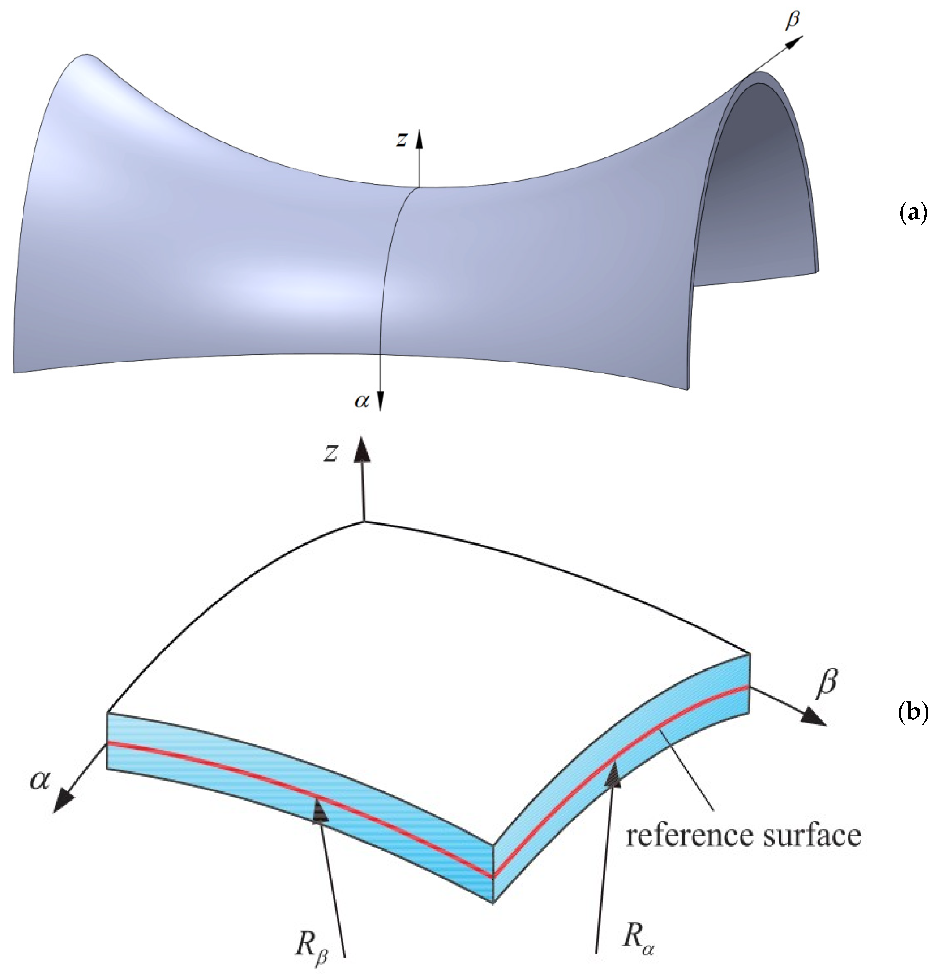
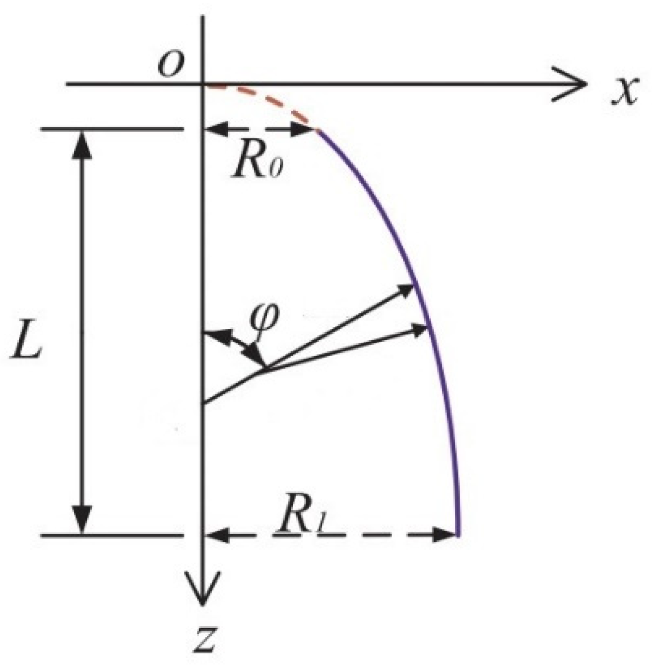
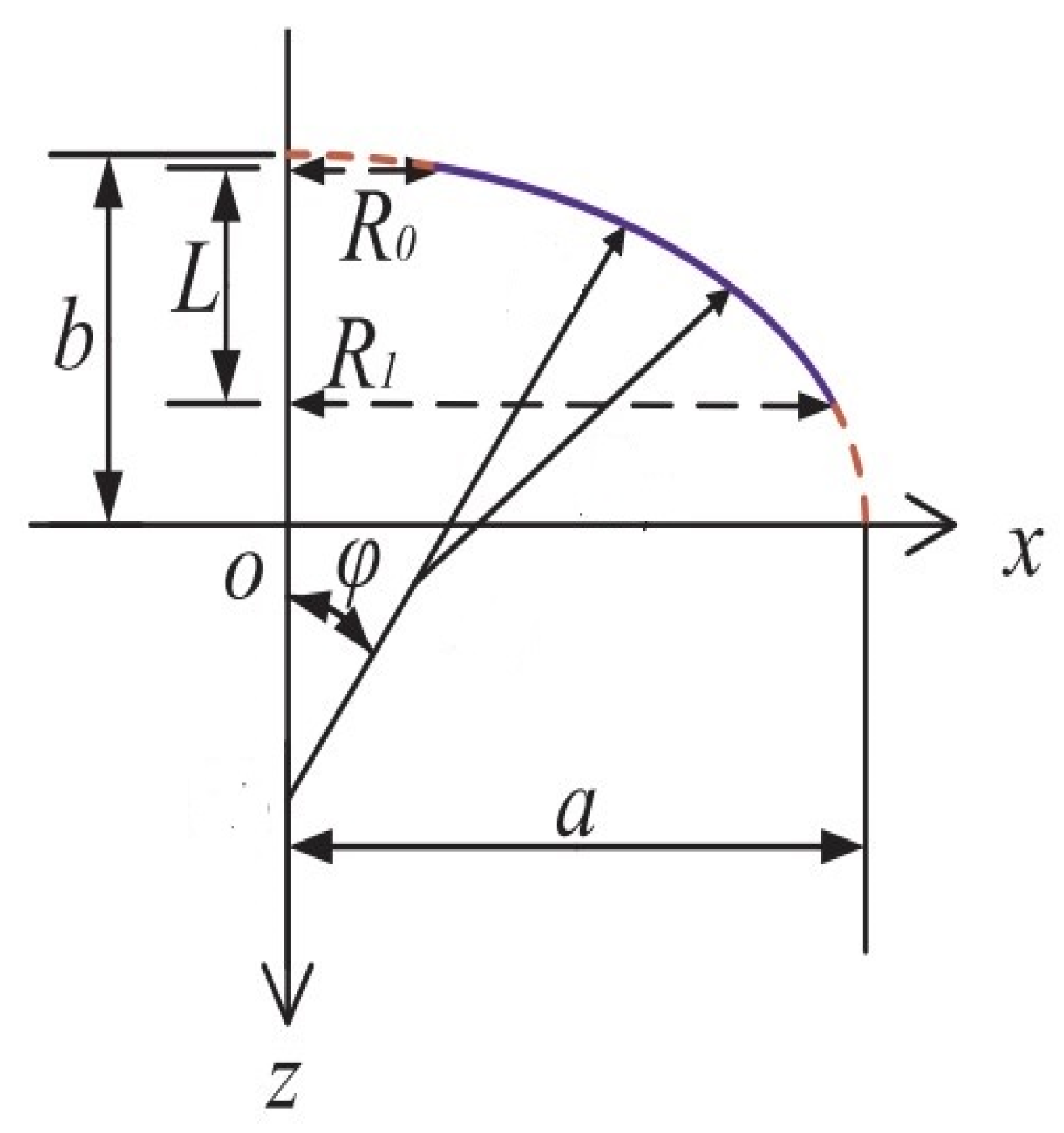
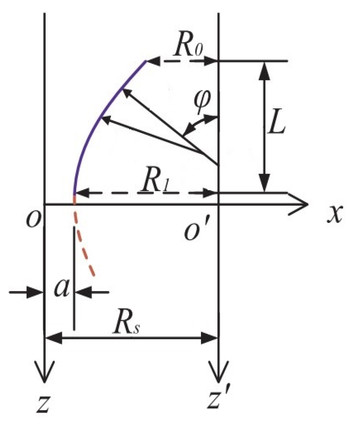
2.1. Explanation of Double-Curved Shells of Revolution
2.2. Preliminaries
2.3. Energy Functional of Each Segment
2.4. Motion Equations and Solution Methodology
3. Numerical Results and Discussion
4. Conclusions
Author Contributions
Funding
Institutional Review Board Statement
Data Availability Statement
Acknowledgments
Conflicts of Interest
Appendix A
- (1)
- For the double-curved parabolic shell of revolution, R1 = 0.90 m, R0 = 0.45 m.
- (2)
- For the double-curved elliptic shell of revolution, R1 = 0.45 m, R0 = 0.45 m.
- (3)
- For the double-curved hyperbolic shell of revolution, R1 = 0.45 m, R0 = 0.45 m.
Appendix B
References
- Wang, Q.S.; Shi, D.Y.; Liang, Q.; Pang, F.Z. Free vibrations of composite laminated doubly-curved shells and panels of revolution with general elastic restraints. Appl. Math. Model. 2017, 46, 227–262. [Google Scholar] [CrossRef]
- Guo, H.L.; Du, X.L.; Żur, K.K. On the dynamics of rotating matrix cracked FG-GPLRC cylindrical shells via the element-free IMLS-Ritz method. Eng. Anal. Bound. Elem. 2021, 131, 228–239. [Google Scholar] [CrossRef]
- Nasir, A.M.; Thambiratnam, D.P.; Butler, D.; Austin, P. Dynamics of axisymmetric hyperbolic shell structures. Thin-Walled Struct. 2002, 40, 665–690. [Google Scholar] [CrossRef]
- Ganilova, O.A.; Cartmell, M.P.; Kiley, A. Experimental investigation of the thermoelastic performance of an aerospace aluminium honeycomb composite panel. Compos. Struct. 2021, 257, 113159. [Google Scholar] [CrossRef]
- Rouzaud, C.; Gatuingt, F.; Dorival, O.; Herve, G.; Kovalevsky, L. A new methodology for assessing the global dynamic response of large shell structures under impact loading. Eng. Comput. 2015, 32, 2343–2382. [Google Scholar] [CrossRef]
- Hieu, P.T.; Van Tung, H. Postbuckling behavior of CNT-reinforced composite cylindrical shell surrounded by an elastic medium and subjected to combined mechanical loads in thermal environments. J. Thermoplast. Compos. Mater. 2019, 32, 1319–1346. [Google Scholar] [CrossRef]
- Lee, C.; Wei, X.; Kysar, J.W.; Hone, J. Measurement of the elastic properties and intrinsic strength of monolayer graphene. Science 2008, 321, 385–388. [Google Scholar] [CrossRef]
- Rafiee, M.A.; Rafiee, J.; Wang, Z.; Song, H.; Yu, Z.Z.; Koratkar, N. Enhanced mechanical properties of nanocomposites at low graphene content. ACS Nano 2009, 3, 3884–3890. [Google Scholar] [CrossRef]
- Tabandeh-Khorshid, M.; Kumar, A.; Omrani, E.; Kim, C.; Rohatgi, P. Synthesis, characterization, and properties of graphene reinforced metal-matrix nanocomposites. Compos. Part B Eng. 2020, 183, 107664. [Google Scholar] [CrossRef]
- Kitipornchai, S.; Chen, D.; Yang, J. Free vibration and elastic buckling of functionally graded porous beams reinforced by graphene platelets. Mater. Des. 2017, 116, 656–665. [Google Scholar] [CrossRef]
- Xu, H.; Wang, Y.Q.; Zhang, Y. Free vibration of functionally graded graphene platelet- reinforced porous beams with spinning movement via differential transformation method. Arch. Appl. Mech. 2021, 91, 4817–4834. [Google Scholar] [CrossRef]
- Anirudh, B.; Ganapathi, M.; Anant, C.; Polit, O. A comprehensive analysis of porous graphene- reinforced curved beams by finite element approach using higher-order structural theory: Bending, vibration and buckling. Compos. Struct. 2019, 222, 110899. [Google Scholar] [CrossRef]
- Hung, T.Q.; Duc, D.M.; Tu, T.M. Free and forced vibration characteristics of functionally graded sandwich beam with GPL-reinforced porous core. In Proceedings of the 17th East Asian-Pacific Conference on Structural Engineering and Construction, 2022: EASEC-17, Singapore, 27–30 June 2022; Springer Nature: Singapore, 2023; pp. 1432–1452. [Google Scholar] [CrossRef]
- Yang, J.; Chen, D.; Kitipornchai, S. Buckling and free vibration analyses of functionally graded graphene reinforced porous nanocomposite plates based on Chebyshev-Ritz method. Compos. Struct. 2018, 193, 281–294. [Google Scholar] [CrossRef]
- Reddy, R.M.; Karunasena, W.; Lokuge, W. Free vibration of functionally graded-GPL reinforced composite plates with different boundary conditions. Aerosp. Sci. Technol. 2018, 78, 147–156. [Google Scholar] [CrossRef]
- Pourjabari, A.; Hajilak, Z.E.; Mohammadi, A.; Habibi, M.; Safarpour, H. Effect of porosity on free and forced vibration characteristics of the GPL reinforcement composite nanostructures. Comput. Math. Appl. 2019, 77, 2608–2626. [Google Scholar] [CrossRef]
- Chakravorty, D.; Bandyopadhyay, J.N.; Sinha, P. Finite element free vibration analysis of doubly curved laminated composite shells. J. Sound Vib. 1996, 191, 491–504. [Google Scholar] [CrossRef]
- Leissa, A.W.; Kang, J.H. Three-dimensional vibration analysis of paraboloidal shells. JSME Int. J. Ser. C Mech. Syst. Mach. Elem. Manuf. 2002, 45, 2–7. [Google Scholar] [CrossRef]
- Kang, J.H.; Leissa, A.W. Free vibration analysis of complete paraboloidal shells of revolution with variable thickness and solid paraboloids from a three-dimensional theory. Comput. Struct. 2005, 83, 2594–2608. [Google Scholar] [CrossRef]
- Thakur, S.N.; Ray, C. Static and free vibration analyses of moderately thick hyperbolic paraboloidal cross ply laminated composite shell structure. Structures 2021, 32, 876–888. [Google Scholar] [CrossRef]
- Patel, B.P.; Gupta, S.S.; Loknath, M.S.; Kadu, C.P. Free vibration analysis of functionally graded elliptical cylindrical shells using higher-order theory. Compos. Struct. 2005, 69, 259–270. [Google Scholar] [CrossRef]
- Kim, K.; Jon, Y.; An, K.; Kwak, S.; Han, Y. A solution method for free vibration analysis of coupled laminated composite elliptical-cylindrical-elliptical shell with elastic boundary conditions. J. Ocean. Eng. Sci. 2022, 7, 112–130. [Google Scholar] [CrossRef]
- Tornabene, F.; Fantuzzi, N.; Bacciocchi, M.; Dimitri, R. Free vibrations of composite oval and elliptic cylinders by the generalized differential quadrature method. Thin-Walled Struct. 2015, 97, 114–129. [Google Scholar] [CrossRef]
- Irie, T.; Yamada, G.; Kaneko, Y. Free vibration of a conical shell with variable thickness. J. Sound Vib. 1982, 82, 83–94. [Google Scholar] [CrossRef]
- Lam, K.Y.; Hua, L. Influence of boundary conditions on the frequency characteristics of a rotating truncated circular conical shell. J. Sound Vib. 1999, 223, 171–195. [Google Scholar] [CrossRef]
- Safarpour, M.; Rahimi, A.R.; Alibeigloo, A. Static and free vibration analysis of graphene platelets reinforced composite truncated conical shell, cylindrical shell, and annular plate using theory of elasticity and DQM. Mech. Based Des. Struct. Mach. 2020, 48, 496–524. [Google Scholar] [CrossRef]
- Choe, K.; Kim, K.; Wang, Q. Dynamic analysis of composite laminated doubly-curved revolution shell based on higher order shear deformation theory. Compos. Struct. 2019, 225, 111155. [Google Scholar] [CrossRef]
- Choe, K.; Wang, Q.; Tang, J. Vibration analysis for coupled composite laminated axis-symmetric doubly-curved revolution shell structures by unified Jacobi-Ritz method. Compos. Struct. 2018, 194, 136–157. [Google Scholar] [CrossRef]
- Guo, J.; Shi, D.; Wang, Q.; Tang, J.; Shuai, C. Dynamic analysis of laminated doubly-curved shells with general boundary conditions by means of a domain decomposition method. Int. J. Mech. Sci. 2018, 138, 159–186. [Google Scholar] [CrossRef]
- Zhao, J.; Xie, F.; Wang, A.; Shuai, C.; Tang, J.; Wang, Q. Vibration behavior of the functionally graded porous (FGP) doubly-curved panels and shells of revolution by using a semi-analytical method. Compos. Part B Eng. 2019, 157, 219–238. [Google Scholar] [CrossRef]
- Qu, Y.; Meng, G. Three-dimensional elasticity solution for vibration analysis of functionally graded hollow and solid bodies of revolution. Part I: Theory. Eur. J. Mech.-A/Solids 2014, 44, 222–233. [Google Scholar] [CrossRef]
- Qu, Y.; Meng, G. Dynamic analysis of composite laminated and sandwich hollow bodies of revolution based on three-dimensional elasticity theory. Compos. Struct. 2014, 112, 378–396. [Google Scholar] [CrossRef]
- Qu, Y.; Zhang, W.; Peng, Z.; Meng, G. Nonlinear structural and acoustic responses of three- dimensional elastic cylindrical shells with internal mass-spring systems. Appl. Acoust. 2019, 149, 143–155. [Google Scholar] [CrossRef]
- Qu, Y.; Chen, Y.; Long, X.; Hua, H.; Meng, G. Free and forced vibration analysis of uniform and stepped circular cylindrical shells using a domain decomposition method. Appl. Acoust. 2013, 74, 425–439. [Google Scholar] [CrossRef]
- Yang, S.W.; Hao, Y.X.; Zhang, W.; Yang, L.; Liu, L.T. Free vibration and buckling of eccentric rotating FG-GPLRC cylindrical shell using first-order shear deformation theory. Compos. Struct. 2021, 263, 113728. [Google Scholar] [CrossRef]
- Mao, J.J.; Lu, H.M.; Zhang, W.; Lai, S.K. Vibrations of graphene nanoplatelet reinforced functionally gradient piezoelectric composite microplate based on nonlocal theory. Compos. Struct. 2020, 236, 111813. [Google Scholar] [CrossRef]
- Pang, F.; Li, H.; Wang, X.; Miao, X.; Li, S. A semi analytical method for the free vibration of doubly-curved shells of revolution. Comput. Math. Appl. 2018, 75, 3249–3268. [Google Scholar] [CrossRef]
- Ebrahimi, F.; Dabbagh, A. Vibration analysis of multi-scale hybrid nanocomposite plates based on a Halpin-Tsai homogenization model. Compos. Part B Eng. 2019, 173, 106955. [Google Scholar] [CrossRef]


| Boundary Set | Conditions | |||||
|---|---|---|---|---|---|---|
| Free (F) | \ | 0 | 0 | 0 | 0 | 0 |
| Simply supported (S) | 0 | 1 | 1 | 0 | 0 | |
| Clamped (C) | 1 | 1 | 1 | 1 | 1 |
| N | Q | Present | Pang [37] | FEM |
|---|---|---|---|---|
| 1 | 1 | 0.7059 | 0.6682 | 0.6651 |
| 2 | 0.9922 | 1.0382 | 1.0132 | |
| 3 | 0.9681 | 1.2655 | 1.1721 | |
| 2 | 1 | 0.4976 | 0.4604 | 0.4562 |
| 2 | 0.7506 | 0.8183 | 0.8058 | |
| 3 | 1.0628 | 1.1102 | 1.0445 | |
| 3 | 1 | 0.3326 | 0.3863 | 0.3822 |
| 2 | 0.6712 | 0.6880 | 0.6745 | |
| 3 | 0.9736 | 1.0034 | 0.9427 |
| Pore Coefficients | Paraboloidal Shell | Elliptical Shell | Hyperbolical Shell | |||
|---|---|---|---|---|---|---|
| e0 | O | X | O | X | O | X |
| 0.1 | 2.03569 | 4.27235 | 9.00359 | 18.74518 | 1.88184 | 3.95104 |
| 0.2 | 1.98195 | 4.15957 | 8.76872 | 18.27182 | 1.82875 | 3.83957 |
| 0.3 | 1.92347 | 4.03682 | 8.51282 | 17.75373 | 1.76827 | 3.71259 |
| 0.4 | 1.85912 | 3.90176 | 8.23100 | 17.18060 | 1.69853 | 3.56617 |
| 0.5 | 1.78733 | 3.75110 | 7.91633 | 16.53779 | 1.61692 | 3.39483 |
| 0.6 | 1.70574 | 3.57985 | 7.55840 | 15.80341 | 1.51962 | 3.19054 |
| 0.7 | 1.61054 | 3.38005 | 7.14057 | 14.94238 | 1.40068 | 2.94083 |
| Mass Fraction | Paraboloidal Shell | Elliptical Shell | Hyperbolical Shell | |||
|---|---|---|---|---|---|---|
| WG | O | X | O | X | O | X |
| 0 | 1.41053 | 1.41053 | 6.25059 | 6.25059 | 1.27599 | 1.27599 |
| 0.002 | 1.49349 | 2.09767 | 6.61758 | 9.28613 | 1.35105 | 1.89775 |
| 0.004 | 1.57210 | 2.61029 | 6.96515 | 11.54369 | 1.42217 | 2.36174 |
| 0.006 | 1.64696 | 3.03806 | 7.29610 | 13.42173 | 1.48991 | 2.74903 |
| 0.008 | 1.71857 | 3.41304 | 7.61258 | 15.06288 | 1.55471 | 3.08861 |
| 0.01 | 1.78733 | 3.75110 | 7.91633 | 16.53779 | 1.61692 | 3.39483 |
| 0.012 | 1.85354 | 4.06145 | 8.20876 | 17.88762 | 1.67684 | 3.67603 |
| Pore Coefficients | O | X | ||||
|---|---|---|---|---|---|---|
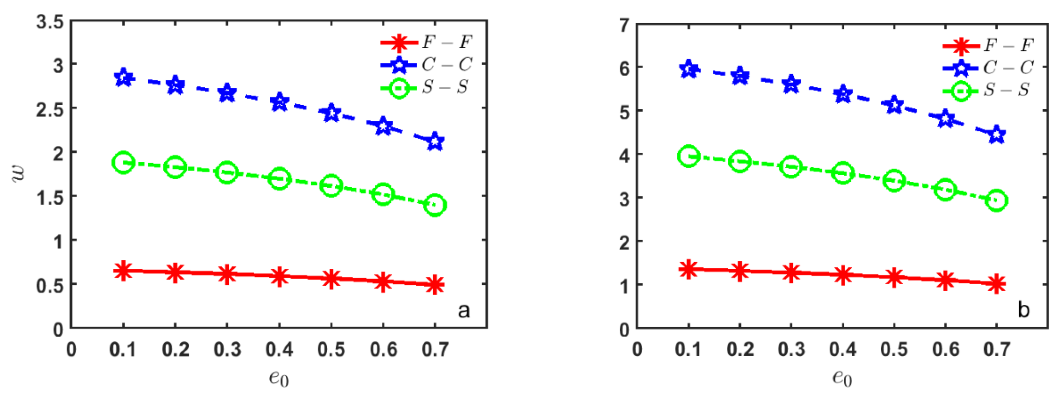
| e0 | F-F | C-C | S-S | F-F | C-C | S-S |
| 0.1 | 0.65595 | 2.84330 | 1.88184 | 1.36224 | 5.96430 | 3.95105 |
| 0.2 | 0.63782 | 2.76306 | 1.82875 | 1.32469 | 5.79599 | 3.83957 |
| 0.3 | 0.61732 | 2.67166 | 1.76827 | 1.28203 | 5.60426 | 3.71259 |
| 0.4 | 0.59368 | 2.56627 | 1.69853 | 1.23301 | 5.38319 | 3.56617 |
| 0.5 | 0.56626 | 2.44294 | 1.61692 | 1.17590 | 5.12448 | 3.39483 |
| 0.6 | 0.53365 | 2.29589 | 1.51962 | 1.10841 | 4.81601 | 3.19054 |
| 0.7 | 0.49442 | 2.11613 | 1.40069 | 1.02693 | 4.43894 | 2.94083 |
| Mass Fraction | O | X | ||||
|---|---|---|---|---|---|---|
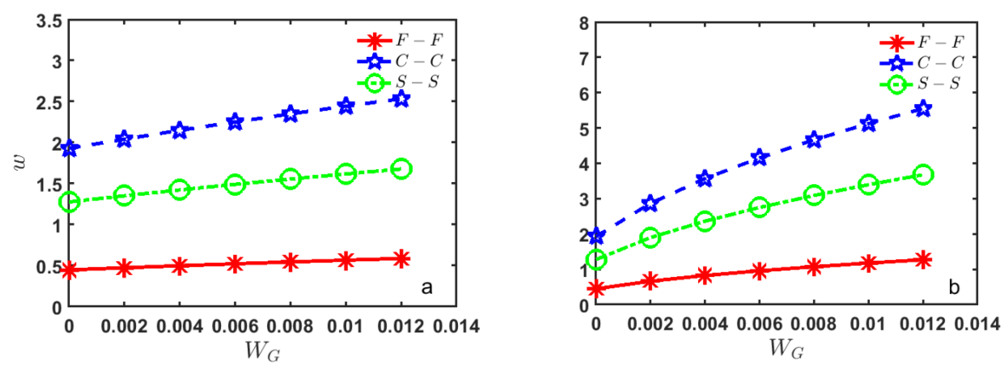
| WG | F-F | C-C | S-S | F-F | C-C | S-S |
| 0 | 0.44735 | 1.92803 | 1.27599 | 0.44735 | 1.92803 | 1.27599 |
| 0.002 | 0.47355 | 2.04141 | 1.35105 | 0.66375 | 2.86695 | 1.89775 |
| 0.004 | 0.49833 | 2.14883 | 1.42217 | 0.82404 | 3.56718 | 2.36174 |
| 0.006 | 0.52196 | 2.25113 | 1.48991 | 0.95683 | 4.15130 | 2.74903 |
| 0.008 | 0.54454 | 2.34899 | 1.55471 | 1.07244 | 4.66317 | 3.08861 |
| 0.01 | 0.56626 | 2.44294 | 1.61692 | 1.17590 | 5.12448 | 3.39483 |
| 0.012 | 0.58702 | 2.53341 | 1.67684 | 1.27026 | 5.54785 | 3.67603 |
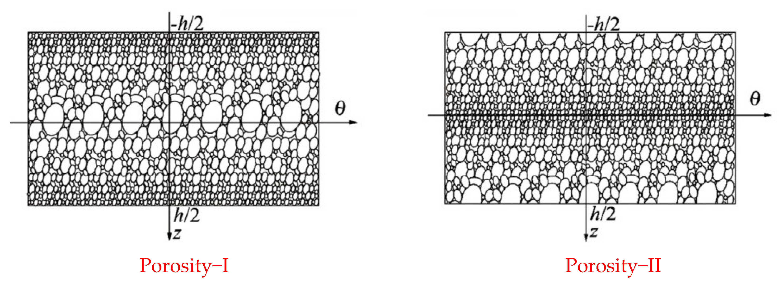
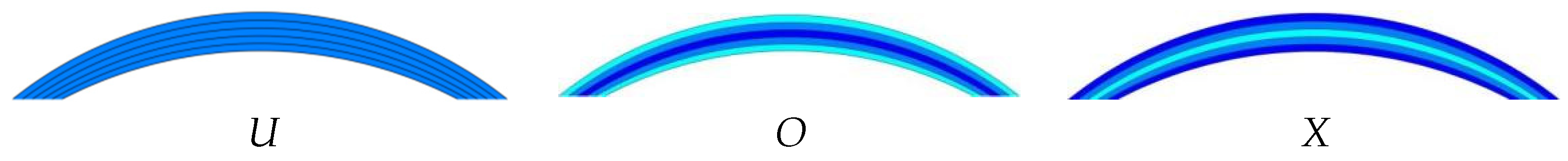
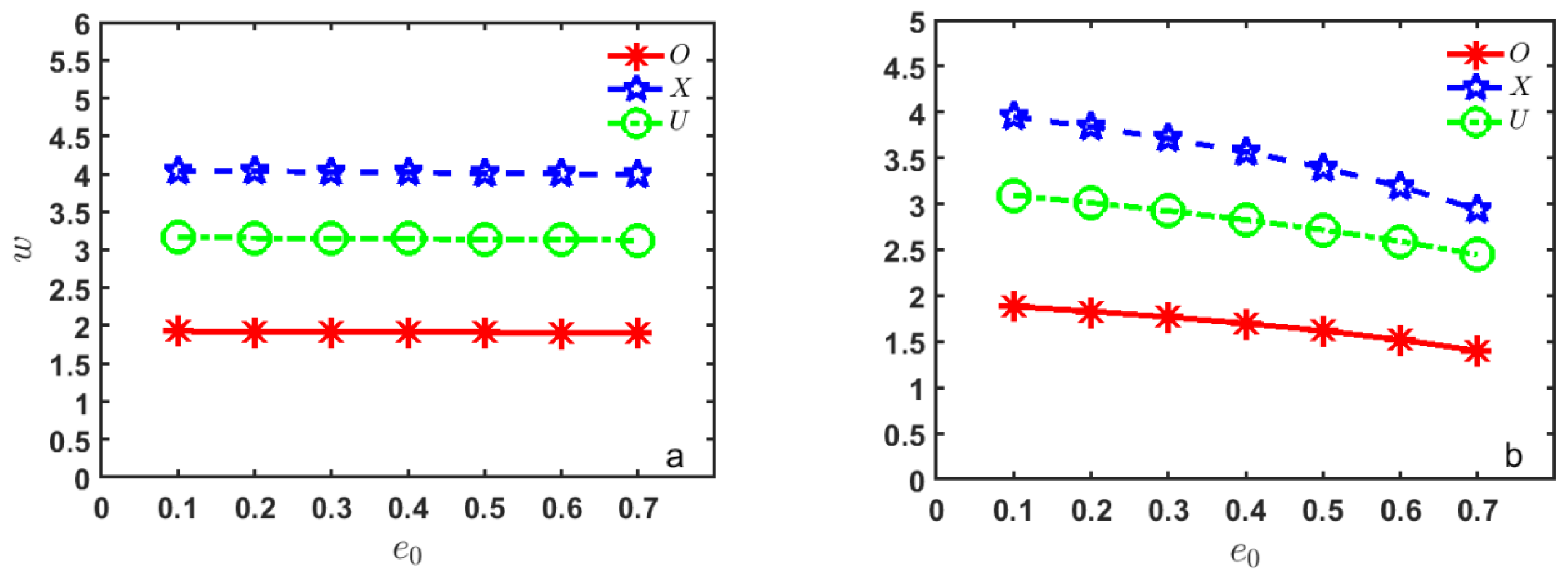
| Pore Coefficients | Porosity-I S-S Boundary Conditions | Porosity-II S-S Boundary Conditions | ||||
|---|---|---|---|---|---|---|
| e0 | X | O | U | X | O | U |
| 0.1 | 4.04194 | 1.92513 | 3.16400 | 3.95105 | 1.88184 | 3.09452 |
| 0.2 | 4.03394 | 1.92132 | 3.15774 | 3.83957 | 1.82875 | 3.01282 |
| 0.3 | 4.02591 | 1.91750 | 3.15146 | 3.71259 | 1.76827 | 2.92390 |
| 0.4 | 4.01785 | 1.91366 | 3.14515 | 3.56617 | 1.69853 | 2.82606 |
| 0.5 | 4.00975 | 1.90980 | 3.13880 | 3.39483 | 1.61692 | 2.71691 |
| 0.6 | 4.00160 | 1.90592 | 3.13243 | 3.19054 | 1.51962 | 2.59285 |
| 0.7 | 3.99343 | 1.90203 | 3.12603 | 2.94083 | 1.40069 | 2.44809 |
Disclaimer/Publisher’s Note: The statements, opinions and data contained in all publications are solely those of the individual author(s) and contributor(s) and not of MDPI and/or the editor(s). MDPI and/or the editor(s) disclaim responsibility for any injury to people or property resulting from any ideas, methods, instructions or products referred to in the content. |
© 2024 by the authors. Licensee MDPI, Basel, Switzerland. This article is an open access article distributed under the terms and conditions of the Creative Commons Attribution (CC BY) license (https://creativecommons.org/licenses/by/4.0/).
Share and Cite
Wang, A.; Zhang, K. Free Vibration of Graphene Nanoplatelet-Reinforced Porous Double-Curved Shells of Revolution with a General Radius of Curvature Based on a Semi-Analytical Method. Mathematics 2024, 12, 3060. https://doi.org/10.3390/math12193060
Wang A, Zhang K. Free Vibration of Graphene Nanoplatelet-Reinforced Porous Double-Curved Shells of Revolution with a General Radius of Curvature Based on a Semi-Analytical Method. Mathematics. 2024; 12(19):3060. https://doi.org/10.3390/math12193060
Chicago/Turabian StyleWang, Aiwen, and Kairui Zhang. 2024. "Free Vibration of Graphene Nanoplatelet-Reinforced Porous Double-Curved Shells of Revolution with a General Radius of Curvature Based on a Semi-Analytical Method" Mathematics 12, no. 19: 3060. https://doi.org/10.3390/math12193060