Article

Modeling the Dynamics of Prosthetic Fingers for the Development of Predictive Control Algorithms

by
José Vicente García-Ortíz
1,*,
Marta C. Mora
1 and
Joaquín Cerdá-Boluda
2
1
Departament d’Enginyeria Mecànica i Construcció (EMC), Universitat Jaume I, 12071 Castelló de la Plana, Spain
2
Instituto de Instrumentación para Imagen Molecular (I3M), Universitat Politècnica de València, 46020 Valencia, Spain
*
Author to whom correspondence should be addressed.
Mathematics 2024, 12(20), 3236; https://doi.org/10.3390/math12203236
Submission received: 17 September 2024 / Revised: 11 October 2024 / Accepted: 12 October 2024 / Published: 16 October 2024

Abstract

:
In the field of biomechanical modeling, the development of a prosthetic hand with dexterity comparable to the human hand is a multidisciplinary challenge involving complex mechatronic systems, intuitive control schemes, and effective body interfaces. Most current commercial prostheses offer limited functionality, typically only one or two degrees of freedom (DoF), resulting in reduced user adoption due to discomfort and lack of functionality. This research aims to design a computationally efficient low-level control algorithm for prosthetic hand fingers to be able to (a) accurately manage finger positions, (b) anticipate future information, and (c) minimize power consumption. The methodology employed is known as model-based predictive control (MBPC) and starts with the application of linear identification techniques to model the system dynamics. Then, the identified model is used to implement a generalized predictive control (GPC) algorithm, which optimizes the control effort and system performance. A test bench is used for experimental validation, and the results demonstrate that the proposed control scheme significantly improves the prosthesis’ dexterity and energy efficiency, enhancing its potential for daily use by people with hand loss.

1. Introduction

The replacement of the human hand by a prosthesis with a dexterity that allows the subject to perform most of the activities of daily living (ADL) that were previously performed with the original hand is a multidisciplinary engineering challenge since it requires the development of complex mechatronic systems, intuitive control schemes, and clinically sound interfaces with the body.
Currently, most commercial prostheses only allow for the execution of one or two degrees of freedom (DoF) activated by an event that switches between one movement or the other [1]. The typically generated movements are the opening and closing of the hand, as well as the rotation of the wrist. This lack of dexterity hinders effective hand rehabilitation and results in patients rarely using the prostheses during activities of daily living [2,3]. Instead, they continue to use mechanically actuated non-anthropomorphic one-DoF prostheses extensively. In fact, the simplicity of hand prostheses from a biomechanical point of view is due, fundamentally, to the complexity of establishing an adequate interaction between the subject and a dexterous prosthesis with multiple degrees of freedom. The main reason for the use of more DoF is to increase the number of possible grasps made by the prosthesis and, therefore, to increase its dexterity. It has been shown that the implementation of two grasp types (cylindrical and pulp pinch) would cover 50% of ADLs, and the expansion to eight grasp types would cover over 90% of ADLs [4].
However, although advanced prosthetic hands exist that are mechanically capable of forming the functional grips necessary to perform ADL, the control schemes implemented in these devices are far from the coordinated control produced by the intact neuromuscular system. In fact, the main reasons for abandoning the prosthesis are discomfort and lack of functionality due to complex or unnatural control or slow response to user commands [5,6,7,8].
A great amount of work and effort has been invested in recent times to avoid abandoning the problem, but there are multiple issues still to be solved [8]. First, the interface between a human and a machine must be comfortable and naturally integrated into daily activity. Some studies have addressed the optimization of sensor positioning in order to maximize the quality of the signal obtained [9].
Secondly, it is necessary that the classification algorithms work quickly, in real time, and robustly, thus minimizing possible errors in recognizing the type of grip that the user desires to make. In this sense, the critical emergence of machine learning (ML) techniques to solve the problem is notable [10].
To cite some representative examples and some of the philosophies that are being explored most widely, Kadavath et al. [11] used four traditional ML models for classifying finger movements into seven distinct gestures. They concluded that Random Forest emerges as the top performer, consistently delivering superior precision. For their part, the authors explored the use of a simple multilayer perceptron in the classification process, which led them to obtain success rates close to 80% in real time and under very rigorous resource and consumption restrictions [12]. Another very promising technology that is being explored in the literature is Support Vector Machines (SVM), which constitute one of the privileged directions of advancement in the immediate future [13].
However, in contrast to the evident large number of studies focused on the high-level control part of hand prostheses, the relative lack of contributions in the physical part of the problem is striking, where new proposals appear very sporadically [14] and, sometimes, the techniques used are not even mentioned in the developments. In fact, the low-level control schemes used in current prosthetics are very simple, mainly of the proportional (P) type, usually referred to as Direct Control [15], or proportional–integral–derivative (PID) type [16,17], prioritizing the robustness of the system instead of performance. However, there are hardly any works that include the modeling of the system to be controlled (the motors of the hand) and the development of appropriate algorithms.
In addition, there is no dilemma between performance and stability. The key is to have a good model of the system and to use more advanced control algorithms where not only the response of the system is considered but also the control effort. Therefore, a range of algorithms based on a cost index opens up, where their design can consider both parts of the control: performance and stability. This family of algorithms is based on optimal control, and specifically, there is an ideal subfamily for prostheses control: model-based predictive control (MBPC) algorithms [18,19,20]. This implies the need to obtain a good model of the system in order to design a low-level controller that offers good performance in terms of low computational cost and energy consumption, as well as stability. Thus, the trajectory of the fingers of the prosthetic hand could correspond to the trajectory of those of the human hand with low energy consumption.
This work proposes a model-based generalized predictive control (GPC) algorithm with future information for prosthetic hand fingers that solves the abovementioned problems and improves the prosthesis’ stability and performance in terms of computational cost, grip execution, and energy consumption. To the authors’ knowledge, this is the first time a GPC with future information is used in hand prostheses.
This paper is structured as follows. In Section 2, the aim of this paper is detailed. Section 3 describes the prosthetic hand used, the linear identification process, and the algorithms developed. Section 4 details the results of both the identification and control processes. Section 5 discusses the results obtained, and finally, Section 6 draws the conclusions of this work.

2. Aim

The aim of this work is to design an algorithm for the low-level control of the fingers of an artificial hand based on a proper mathematical model of the fingers’ dynamics obtained from experimental information. For this purpose, a mathematical protocol is proposed that involves the following three steps: (a) system identification and modeling; (b) development of control algorithms; (c) testing and comparison.
The control algorithm must comply with several requirements:
  • Low computational cost;
  • Stability;
  • Managing future information that may be known;
  • Accurately managing the finger position in a determined and predefined trajectory;
  • Reducing the power consumption with respect to those in the literature since human-embedded prosthetic hands are powered by a battery.

3. Materials and Methods

In order to develop this work, it is necessary to have, on the one hand, a test bench capable of obtaining experimental results under certain conditions and, on the other hand, to use the proper mathematical models and techniques to obtain the desired results.
Regarding the mathematical techniques employed in this work, two types of algorithms are used: first, algorithms for linear identification of systems and second, control algorithms able to correctly manage the fingers’ trajectories.

3.1. The Prosthetic Hand

In this work, a 3D-printed mechanical hand developed by the Biomechanics and Ergonomics research group of the Universitat Jaume I has been used as a prosthetic hand. The artificial hand, called BRUJA Hand, [21], has six degrees of freedom and it is composed of a rod mechanism with one DoF for each of the finger flexions and a sixth degree for the abduction of the thumb. Each of the fingers of the hand is made up of three sections or phalanges, except for the thumb, which has two. Since the fingers are formed by one degree of freedom rod mechanism, the position of each finger is directly and necessarily determined by the position of the electric motor. The BRUJA Hand is depicted in Figure 1.

3.2. Linear Identification Process

The linear identification process arises from the need to obtain a linear model of a system’s behavior. It is a widely used procedure in systems where the physics is unknown or simply subject to a series of uncertainties that distance the physical model from the real behavior. In an artificial hand, the mechanical model of a finger can be known sufficiently well by using kinematic and dynamic principles. However, phenomena appear that are difficult to model and that generate uncertainties, such as friction and other irreversibilities, non-linearities of generalized inertia, hysteresis phenomena, etc. Fortunately, physical systems tend to have a linear behavior in certain operating ranges. It is precisely this feature that makes it possible to think that the use of a linear model can be a good alternative, especially when its properties are assessed. The main advantages of using linear models are the low computational cost of their evaluation and the possibility of obtaining a linear model based on experimental data collected in the system to be modeled. The main disadvantage is the loss of physical sense of some internal parameters of the model.
Experimental modeling involves a series of the following steps:
  • First, the main system parameters (input and output) must be determined. The input power to the finger motor is established as a system input. The position of the kinematic chain is established as the system output;
  • Second, an input signal must be applied to the system to excite it, which must fulfill a series of properties [22]. Theoretically, the white noise signal could drive the system at any frequency. However, since white noise is a complex signal, an equivalent signal is proposed that complies with the properties established in [22]. That work establishes the required properties and characteristics for an experiment to provide adequate data for a correct system identification. Based on previous experimentation, a pseudo-random signal is selected for identification purposes;
  • Finally, knowing the system features, a battery of tests to be applied is determined. As gravity acts on the system and produces a constant steering force on all the elements of the kinematic chain of the finger, some tests have been designed in order to assess its effect.
Therefore, the identification experiments in the PACMAR (acronym in Spanish for Automatic Platform for Anthropomorphic and Robotic Hands) TestBench [23] are the following:
  • Palm up;
  • Palm down;
  • Palm perpendicular to the ground.
Once the effective data block for the identification has been determined, the identification is carried out using various algorithms. The data block used is the output increments instead of the output value. The main reason is the integrative behavior performed by the system, which will be developed later.
The linear identification of the system is developed in two phases. The first phase involves the definition of the structure of the linear model. In the second phase, an identification algorithm determines the coefficients of the transfer functions.
Regarding the structure of the model, let us define the unit forward shift operator z as
z x t = x ( t + 1 ) ,
and, consequently, the unit delay operator z–1 as
z 1 x t = x ( t 1 ) .
Most single-input, single-output (SISO) processes can be described by
A z y t = z d B z u t 1 + C z ξ t .
In this expression,
  • u(t) is the input, the control action on the system at time t;
  • y(t) is the output, the value of the system measurements at time t;
  • ξ (t) is the noise of the system at time (t);
  • A(z), B(z), and C(z) are the following polynomials of order na, nb, and nc, respectively:
    A z = 1 + a 1 z 1 + a 2 z 2 + + a n a z n a B z = b 0 + b 1 z 1 + b 2 z 2 + + b n b z n b C z = 1 + c 1 z 1 + c 2 z 2 + + c n c z n c
This model is known as a Controlled Auto-Regressive Moving Average (CARMA) [18]. In the present work, an improved modification of the CARMA model has been selected: the Controlled Auto-Regressive Integrated Moving Average (CARIMA) model [18]. This new model includes an additional step of integration, as can be seen in Figure 2.
This structure has two important terms. The first term contains the transfer function itself, which relates the dominant dynamics of the identified system, directly relating the input to the system with the position of the finger. The second term is based on a totally stochastic, random input. This second input has some special dynamics. On the one hand, it is affected by the same poles as the main dynamics but with an integration of noise. This allows the model to have a drift noise that is able to improve the prediction of values. In addition, it contains a polynomial with some zeros, which will make the model more stable. This fact is understood when the GPC (generalized predictive controller [21,22,23]) is selected as the system control algorithm.
A z y t = B z z d u t 1 + C z ξ ( t ) .
with Δ = 1 − z–1. For simplicity, polynomial C can be chosen to be 1.
For the second phase, which involves the identification of polynomials A and B, several identification algorithms have been tested:
  • Output error (OE);
  • Prediction Error Method (PEM);
  • The Multivariable Output Error State Space Method (N4SID);
  • Auto-Regressive Exogenous (ARX).
First, the number of dominant and representative poles and zeros of the system must be determined. To do this, it is usually sufficient to carry out some initial tests, taking into account that real systems do not usually have very complex dynamics. This implies that it is unlikely to detect systems with more than two dominant poles and one zero, which are representative of the system dynamics. The structure of the polynomials will be as follows: 3 coefficients for polynomial A; 2 coefficients for polynomial B; and 1 natural delay in the discretized system. This structure is optimized by a parametric study carried out by MATLAB® functions.
The identification algorithms used are based on the minimization of the existing error between the measured response of the system and the one predicted by the model (coefficients of the described polynomials). The most commonly used technique is the least squares method. Minimizing the function VLS, it is possible to obtain the coefficients of the polynomials that compose this linear model.
V L S = 1 N t = n + 1 N + n ε ( t ) 2 = 1 N t = n + 1 N + n A z y t B z u ( t ) 2 ,
where
  • VLS is the function of the residual by least squares;
  • n is the order of the system (i.e., the number of parameters of the model);
  • N is the number of samples of the identification sequence (normally N >> n);
  • ε ( t ) is the error;
  • the polynomial A(z) contains the poles of the system;
  • the polynomial B(z) contains the zeros of the system.
After the application of Parseval’s formula, the previous equation is transformed into the frequency domain,
V L S 1 2 π π π G 0 e i ω B e i ω A e i ω 2 A 2 e i ω Φ u ( ω ) d ω + 1 2 π π π A 2 e i ω Φ ν ( ω ) d ω
where G 0 e i ω is the true transfer function; Φ u ( ω ) and Φ ν ( ω ) are the spectra of the input and the disturbance, respectively. The details of the development are described in [24].

3.2.1. Output Error

This algorithm is based on the simple comparison between the predicted output and the experimentally measured output of the system.
ε o e t = y t B ( z ) A ( z ) u t
Assuming that the process order n is known, the output error method estimates parameters by minimizing the loss function:
V O E N = 1 N t = 1 N ε o e ( t ) 2

3.2.2. Prediction Error Method

In this case, the error equation for linear regression is redefined as follows:
y t = a 1 y t 1 a n y t n + b 1 u t 1 + + b n u t n + ε t y t = 1 A z y t + B z u t + ε t
Neglecting the ε t term, it is possible to predict the output error and the minimization of the function can be addressed by the generalized least squares method, leaving the prediction as
A 0 z y t = B 0 z u t + 1 D 0 z ξ t y t = B 0 ( z ) A 0 ( z ) u t + 1 A 0 ( z ) D 0 ( z ) ξ ( t )
where
A 0 z = 1 + a 1 0 z 1 + a 2 0 z 2 + + a n 0 z n B 0 z = b 1 0 z 1 + b 2 0 z 2 + + b n 0 z n D 0 z = 1 + d 1 0 z 1 + d 2 0 z 2 + + d n d 0 z n d
and ξ t is white noise with zero mean and variance R.
Hence, the minimization of VLS is performed using the new model.

3.2.3. N4SID

This algorithm, developed by Van Overschee and De Moor [25], is one of the most used for subspace state space system identification. In this case, the proposed model is based on a state space model.
x t + 1 = A x t + B u t + w t y t = C x t + D u t + v ( t )
In these expressions, A, B, C, and D are matrices of constant coefficients. In this case, a residual equation is generated, that is, the difference between the output measured in the test and the output proposed by the model. This difference should be minimized, although, in the case of state space, there are multiple models that provide the same transfer function model. Signals w(t) and v(t) are random variables due to noise or internal non-linearity behavior.

3.2.4. Auto Regressive eXogenous ARX

The ARX algorithm is used to obtain dynamic models of systems based on experimental data measured from a real system. In this case, it is considered that the system’s dynamics depend on its own history and an exogenous variable. Additionally, errors in the model or due to measurement inaccuracies are also considered.
A z y t = z d B z u t 1 + ξ t
In this expression, A is the vector that contains the numerator of the transfer function to be determined. From this, the poles of the system can be deduced, and consequently, the system’s dominant dynamics. B contains the coefficients of the target transfer function, i.e., the system’s zeros. Finally, Chi is the stochastic random variable that accounts for measurement and modeling errors.
Prior to the identification process, a parametric study of poles, zeros, and the optimal order of the system was conducted. This involved using data to find an optimal structure through specific functions. In this particular case, the MATLAB® function arxstruc was used to determine the order of the A and B polynomials, which provides the most optimal transfer function. In general, choosing the system order does not pose significant issues, as systems in nature rarely have more than two dominant poles or more than one zero.

3.3. Generalized Predictive Control GPC

A control is proposed based on a generalized predictive controller (GPC). This control algorithm is based on 4 pillars:
  • The prediction model (CARIMA);
  • The cost index;
  • The optimization tool;
  • The application of the moving horizon.
The CARIMA model is a model with drift noise and, therefore, tolerant to modeling errors and non-measurable disturbances in the system. It is based on the transfer function obtained from the identification. It also contains a polynomial in the noise part that will serve as a signal-filtering element that provides additional stability to the controller. These concepts are fully developed in Clarke’s articles [21,22,23]. Regarding the cost index, it is important to remark that it allows for the inclusion, in the design process, of not only the cost of the error but also the cost of control. The cost of the error is the term that gives importance to not having the system controlled, that is, to having a non-zero error. The cost of control gives importance to the cost of sudden variations in control actions. In an ideal system, this cost is expressed in monetary units. In short, predictive control is based on optimal control and, therefore, the search for actions that minimize the total cost based on objective criteria.

4. Results

This section presents all the experimental tests carried out and all the results of the application of the mathematical algorithms. It is divided into two subsections: the first one details the identification experiments carried out, and the second one explains the predictive control algorithms used.

4.1. Identification

4.1.1. Tests

For the identification of the process, a design of experiments has been developed to determine the tests and the characteristics of the inputs to the system that comply with the specifications. As already determined in [26], the ideal signal used for identification would be the white noise. However, it is known that pseudo-random inputs (PRBS) [19] have the required characteristics and are easier to implement and, therefore, have been used in these experiments. In addition, the input values must be sufficient to excite the system and generate an observable response.
The experiments have been performed on the hand in three different postures with the aim of determining the effect of gravity on the identified model: palm up, palm down, and palm perpendicular to the ground. As a mechanical system, it is subject to a field of conservative forces that affects the desired posture indicated by the behavior.

4.1.2. Identification Results

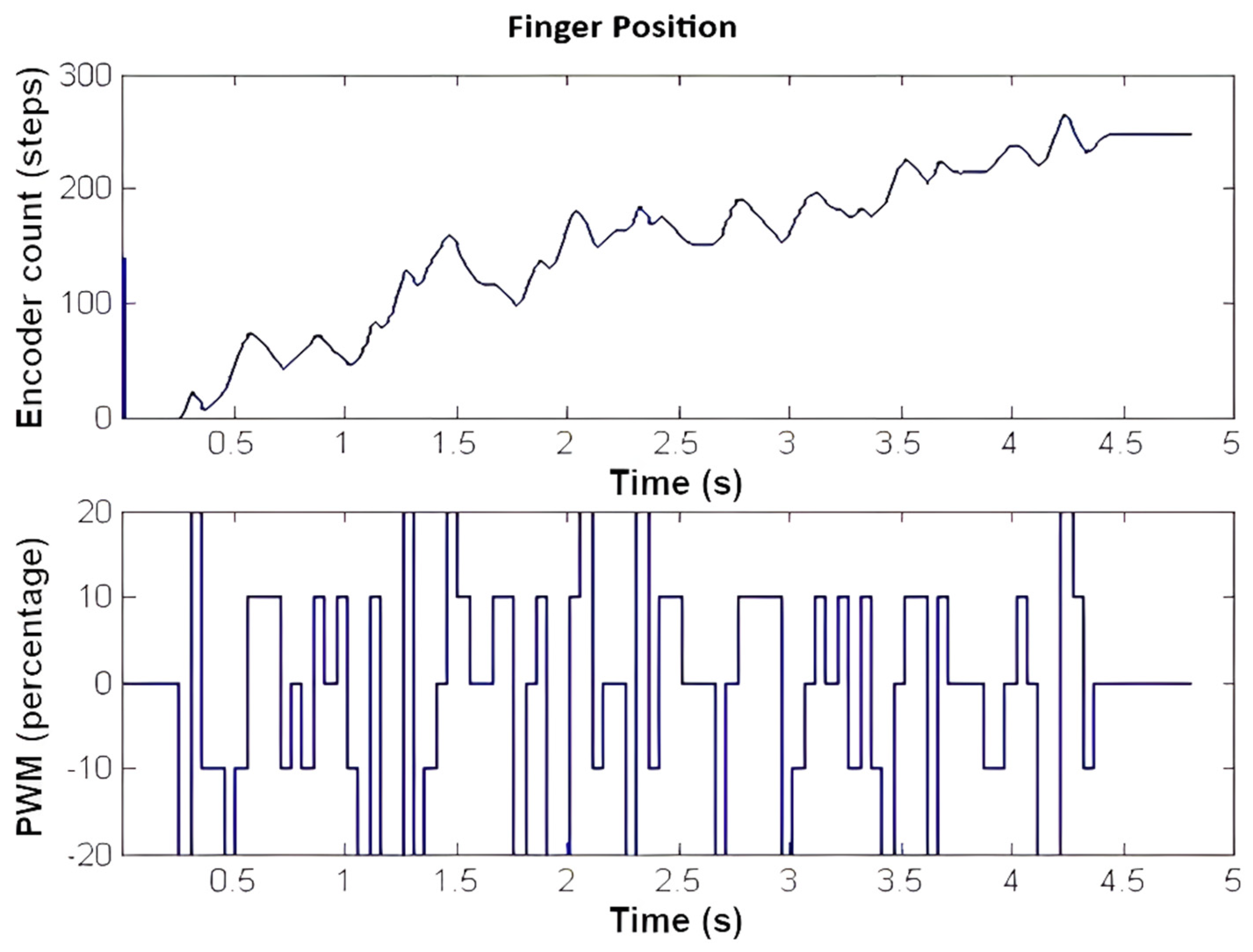
Figure 3 shows an example of the signals obtained from the identification experiment, where the time is represented on the X-axis. The lower part of the figure represents the control action in percentage (PWM). The control action is applied with a maximum of +20% and a minimum of −20%. In addition, the deterministic steps are set every 10%. The upper part represents the response of the system, that is, the finger position. Specifically, it represents the number of counts of an incremental encoder located on the axis of the DC motor that moves the finger. It can be seen that the signal is well-designed (with a range ± 20% of the control action) since it is exciting to the system, and the time ranges allow for setting the dominant trends in the finger dynamics.
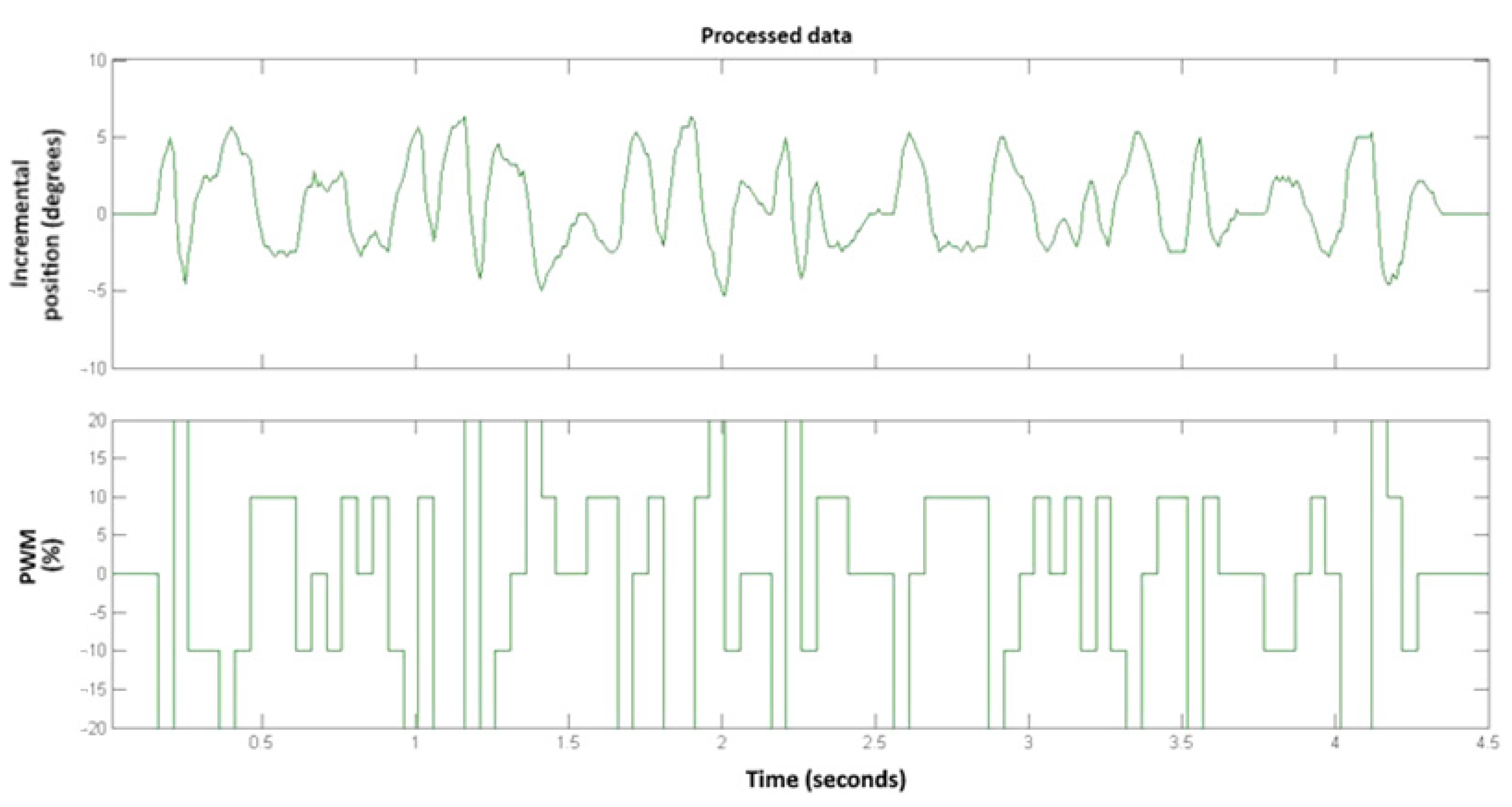
One of the most important characteristics that can be observed is the fact that the system does not return to zero after the applied excitation. This is related to the fact that the absence of control action paralyzes the movement. This effect indicates that the system has an integrator or is a type 1 system [19] since null control actions do not generate movements in the finger position in a steady state. This effect must be removed [27,28] to make the identification algorithms more efficient, and the integrator must be included after obtaining the model. For that reason, data pre-processing is required to filter the data properly, with the resulting signal displayed in Figure 4. The most important actions that have been carried out on the system are increasing the output and the filtering of the high frequencies.
Table 1 presents the results of the identification produced by the various algorithms used. In the first column, the algorithm used is indicated. The second column shows the percentage of agreement between the identified model and the data used to identify the model. The last column gives the degree of agreement between the identified model and the validation data, which give the worst results. The data used to identify the model are the data with the palm of the hand perpendicular to the ground. For validation data, data with the palm facing up were used, which gave a non-linear behavior.
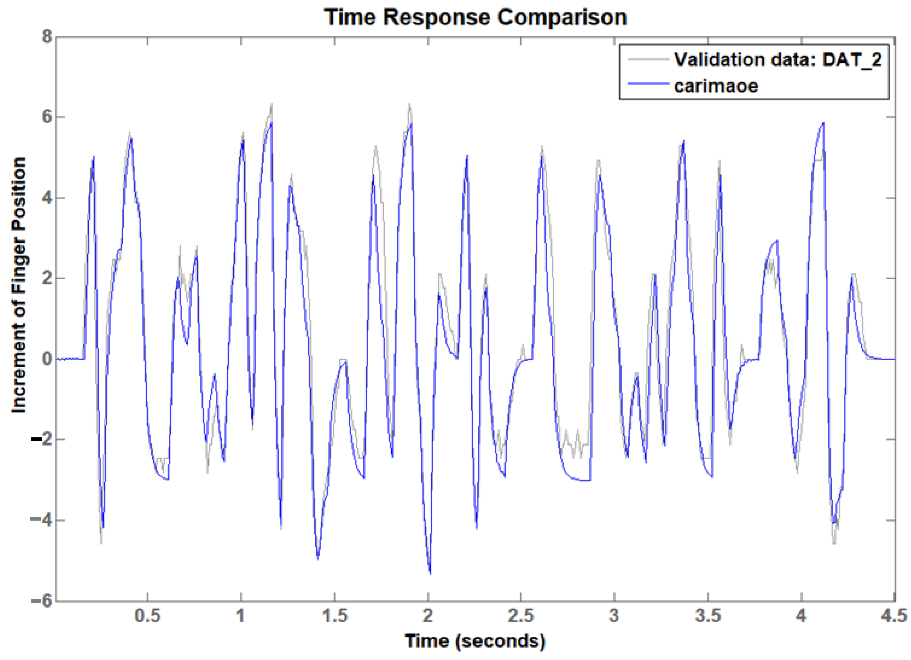
Figure 5 shows the agreement between the modeled response (in blue) and the validation data (in gray). With these results, a model is obtained that efficiently represents reality well, a fact that makes it possible to design a control for the system.

4.2. Control

As the last step, the model is applied together with the design of predictive control for the design of an optimal controller that manages the controlled finger. The Model-Based Predictive Controller (MBPC), and more specifically, the generalized predictive controller (GPC), is a control algorithm based on the minimization of a control cost function J u [21,22]. The control cost function is the weighted addition of two elements: the error and the control.
J u = α i = N 1 N 2 y i y S P i 2 + λ j = 1 N u u j 2
In this equation,
  • u is the vector of increase in future control actions;
  • N1, N2 is the prediction horizon (samples);
  • Nu corresponds to the control horizon (samples);
  • y i is the predicted response of the system;
  • y S P i is the vector of future set points;
  • α, λ are the weights of the contributions.
The cost of the error corresponds to the first term of the equation, that is, the cost of not having the system at the set point. The second term weighs the cost of operating the motor and, therefore, the cost of energy that the movement of the finger will have.
The parameters used for this calculation are obtained according to the experience: N1 = 1; N2 = 50; Nu = 10; α = 0.8, λ = 1.
N1 and N2 refer to the number of samples for which the system output is computed by the GPC. This prediction horizon contains the main dynamic performance of the system identified from an impulse input [23] by simulation in MATLAB®.
Nu denotes the number of samples for which the control action [23] is computed in the optimization process, containing the main part of the dynamics. Low values of Nu with non-minimum phase zeros systems lead to very stable controllers but with poor performance. As the value of Nu increases, the performance improves as the resulting dynamics are more similar to the reference. This improvement is evident starting from a value of Nu = 5. Different values were tested in the simulation, and the final value of Nu = 10 was selected due to the good controller performance.
In the cost function (14), the error cost [22] included in the first part of the equation is the integrated value of the error multiplied by α and must have the same order of magnitude as the control cost (second part of the equation). Thus, α represents the importance of the error, as it is a measure of the prosthesis performance. The last parameter, λ, is the relevance of the battery consumption. In this case, the performance is as significant as the energy consumption, and, therefore, initial simulations in MATLAB® were run with values α = λ = 1. With such values, very good performance was obtained, but the control actions were found to be too aggressive. Consequently, a small reduction in α was carried out, and the final values were set to α = 0.8 and λ = 1, where the control cost and the error cost were good enough.
It is worth noting that the algorithm is fed with 20 future samples of information about the value of the reference. However, as the prediction horizon is N2 = 50, the values of ysp from samples 21 to 50 are estimated to be the same as the last series value (for i = 20).
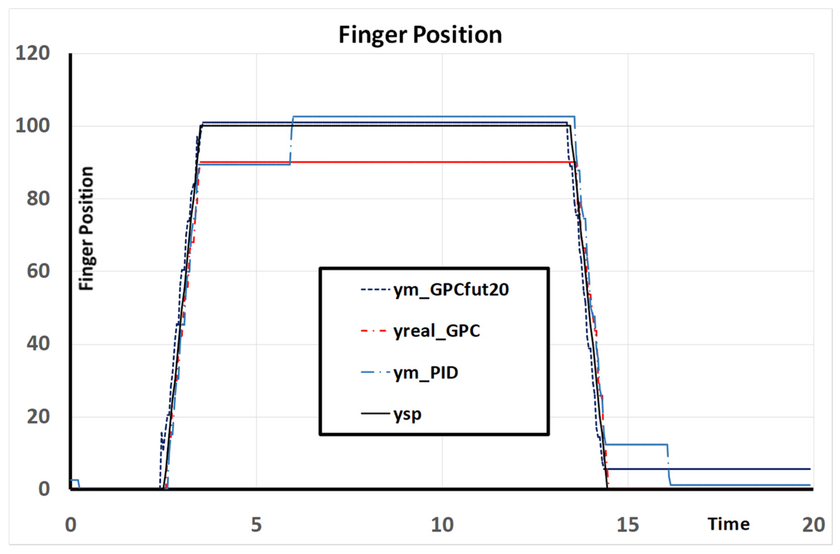
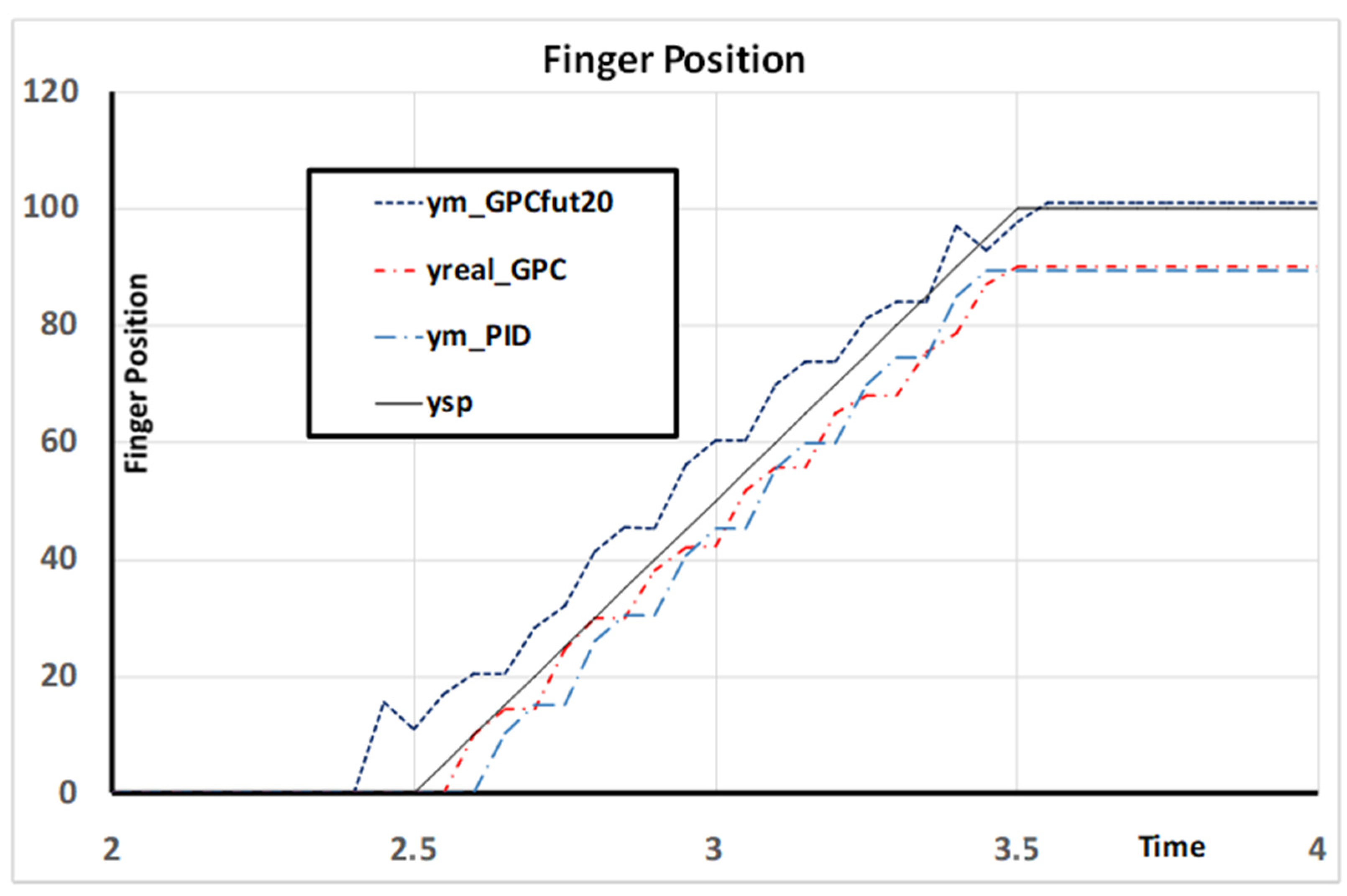
Figure 6 shows the response of the system controlled by different control algorithms: the PID designed according to the Ziegler–Nichols tables (due to the importance of robustness in prosthetic hands), the GPC designed according to the indicated parameters and, finally, the same GPC but feeding it with future information with 20 samples, all of them against a specific test. The test consists of the following:
  • Start from rest;
  • Beginning at 2.5 s and ending at 3.5 s, increase the set point value from 0 to 100;
  • Beginning at 13.4 s and ending at 14.4 s, with the linear decrease to 0.
Figure 6 shows that, in general, all the implemented controllers followed the set point line during the transient period. However, GPC and PID had an initial position error that was lately corrected by the PID but not by the GPC. It is worth noting that the best behavior is carried out by the GPC with future information. The reader can observe that when future information is used, the finger position is moved earlier than without it.
Figure 7 shows the control actions applied to the system by different control algorithms. The algorithm, using future information, makes decisions before the set point changes. This is because future information is utilized to predict performance and advance the system’s response, minimizing control costs. Figure 8 provides a zoomed-in view of Figure 6, focusing on the initial rise between the second and fourth seconds. The GPC with future information responded quicker to the set point, allowing the system to reach the target before the other controllers.

5. Discussion

This article presents a comprehensive procedure for the development and design of generalized predictive control (GPC) algorithms, from model identification to the final adjustment of the control algorithm’s behavior. This article offers an experimentally feasible alternative to the commonly used PID control algorithms (generally without the derivative component) frequently applied in prosthetic control. In this way, a position controller is obtained that provides stability along with performance, whereas in PID algorithms, these are often conflicting properties.
There are some algorithms with properties similar to GPC; however, they typically employ complex non-linear models and optimization algorithms that rely on iterative methods, leading to high computational costs. While these computational challenges can be addressed by utilizing high-performance electronics, this often results in increased system complexity, power consumption, and overall cost, which may not be suitable for prosthetic devices that require portability, energy efficiency, and affordability.
Nevertheless, the approach presented in this article is designed to operate efficiently on low-cost electronics, making it an attractive solution for practical applications in prosthetic control. Furthermore, GPC has the capability to utilize future information, provided it is available. In the case of prosthetic control, finger trajectories are known, depending on the desired type of grasp. Therefore, when future information is utilized, the performance of the GPC is significantly enhanced, surpassing not only the GPC without such information but also the performance of traditional PID control. This demonstrates the superior adaptability and effectiveness of GPC in prosthetic applications, making it a promising alternative for enhancing the functionality and user experience of prosthetic devices.

6. Conclusions

In this study, we developed and evaluated several advanced algorithms for controlling finger movement in prosthetic hands, aiming to enhance both performance and energy efficiency. We successfully established a linear model for finger behavior, which served as the foundation for our investigations. Through a comprehensive comparison of identification algorithms, we identified that the Auto Regressive Exogenous (ARX) model yielded superior results in validation evaluations compared to other approaches.
Our research involved designing a generalized predictive control (GPC) algorithm to effectively manage finger movements. This control strategy was implemented within a prosthetic hand’s control system, while we also exposed a comprehensive procedural algorithm for finger management in such devices. Notably, we identified a Type 1 system for controlling the finger within a four-bar mechanism and developed a model-based predictive control (MBPC) approach to complement the GPC algorithm.
In our experiments, we incorporated future trajectory information, which significantly influenced the performance of our control systems. A comparison of three distinct algorithms revealed that the GPC controller outperformed the Proportional–Integral (PI) controller in terms of both performance and energy consumption. Furthermore, incorporating future information into the GPC control strategy resulted in the best overall performance.
In conclusion, our study demonstrates that the GPC controller, particularly when enhanced with future information, represents a significant advancement in the control of prosthetic hand fingers. This approach not only improves the accuracy and efficiency of finger movement but also offers valuable insights for future developments in prosthetic technology.

Author Contributions

Conceptualization, M.C.M. and J.V.G.-O.; methodology, M.C.M. and J.V.G.-O.; software, J.V.G.-O.; validation, J.V.G.-O.; formal analysis, M.C.M. and J.C.-B.; investigation, M.C.M., J.V.G.-O. and J.C.-B.; resources, M.C.M., J.V.G.-O. and J.C.-B.; data curation, M.C.M.; writing—original draft preparation, M.C.M. and J.C.-B.; writing—review and editing, M.C.M., J.C.-B. and J.V.G.-O.; visualization, M.C.M.; supervision, M.C.M. and J.V.G.-O.; project administration, M.C.M.; funding acquisition, M.C.M. and J.V.G.-O. All authors have read and agreed to the published version of the manuscript.

Funding

This research was funded by the Spanish Ministry of Economy, Industry and Competitiveness (Grant no: PID2020-118021RB-I00/AEI/10.13039/501100011033) and Universitat Jaume I (Grant no: UJI-B2022-48).

Data Availability Statement

The data presented in this study are available upon request from the corresponding author.

Acknowledgments

We thank Sergio Arambul for his developments in a Programming algorithm and his participation in the laboratory experiments. We also thank José F. Fuentes-Ballesteros for his support with the material used in the laboratory experiments.

Conflicts of Interest

The authors declare no conflicts of interest. The funders had no role in the design of this study, in the collection, analyses, or interpretation of data, in the writing of this manuscript, or in the decision to publish the results.

References

  1. Weir, R.F. Design of artificial arms and hands for prosthetic applications. In Standard Handbook of Biomedical Engineering and Design; Kutz, M., Ed.; McGraw-Hill: New York, NY, USA, 2003; Chapter 32. [Google Scholar]
  2. Atkins, D.J.; Heard, D.C.Y.; Donovan, W.H. Epidemiologic overview of individuals with upper-limb loss and their reported research priorities. J. Prosthet. Orthot. 1996, 8, 2–11. [Google Scholar] [CrossRef]
  3. Yang, D.; Jiang, L.; Huang, Q.; Liu, R.Q.; Liu, H. Experimental study of an EMG-controlled 5-DOF anthropomorphic prosthetic hand for motion restoration. J. Intell. Robot. Syst. 2014, 76, 427–441. [Google Scholar] [CrossRef]
  4. Vergara, M.; Sancho-Brú, J.L.; Gracia-Ibáñez, V.; Pérez-González, A. An introductory study of common grasps used by adults during performance of activities of daily living. J. Hand Ther. 2014, 27, 225–234. [Google Scholar] [CrossRef] [PubMed]
  5. Blana, D.; Kyriacou, T.; Lambrecht, J.M.; Chadwick, E.K. Feasibility of using combined EMG and kinematic signals for prosthesis control: A simulation study using a virtual reality environment. J. Electromyogr. Kinesiol. 2016, 29, 21–27. [Google Scholar] [CrossRef] [PubMed]
  6. Espinosa, M.; Nathan-Roberts, D. Understanding Prosthetic Abandonment. Proc. Hum. Factors Ergon. Soc. Annu. Meet. 2019, 63, 1644–1648. [Google Scholar] [CrossRef]
  7. Smail, L.C.; Neal, C.; Wilkins, C.; Packham, T.L. Comfort and function remain key factors in upper limb prosthetic abandonment: Findings of a scoping review. Disabil. Rehabil. Assist. Technol. 2020, 10, 1–10. [Google Scholar] [CrossRef] [PubMed]
  8. Al-Owaidi, N.; Mora, M.C.; Ventura, S. Analysis on the Rejection and Device Passivity Problems with Myoelectric Prosthetic Hand Control. In Proceedings of the 28th World Multi-Conference on Systemics, Cybernetics and Informatics; Callaos, N., Gaile-Sarkane, E., Lace, N., Sánchez, B., Savoie, M., Eds.; International Institute of Informatics and Cybernetics: Winter Garden, FL, USA, 2024; pp. 10–17. [Google Scholar]
  9. Chaplot, L.; Houshmand, S.; Martinez, K.B.; Andersen, J.; Rouhani, H. Optimizing Sensor Placement and Machine Learning Techniques for Accurate Hand Gesture Classification. Electronics 2024, 13, 3072. [Google Scholar] [CrossRef]
  10. Sahoo, J.P.; Sahoo, G.K.; Mohapatra, N.R. Hand Gesture Recognition Based on Surface EMG Using Feature Fusion and Machine Learning Approaches. In Proceedings of the 3rd International Conference on Artificial Intelligence for Internet of Things (AIIoT), Vellore, India, 3–4 May 2024. [Google Scholar]
  11. Kadavath, M.R.K.; Nasor, M.; Imran, A. Enhanced Hand Gesture Recognition with Surface Electromyogram and Machine Learning. Sensors 2024, 24, 5231. [Google Scholar] [CrossRef] [PubMed]
  12. Mora, M.C.; García-Ortiz, J.V.; Cerdá-Boluda, J. sEMG-Based Robust Recognition of Grasping Postures with a Machine Learning Approach for Low-Cost Hand Control. Sensors 2024, 24, 2063. [Google Scholar] [CrossRef] [PubMed]
  13. Chen, W.; Zhang, Z. Hand Gesture Recognition using sEMG Signals Based on Support Vector Machine. In Proceedings of the 8th Joint International Information Technology and Artificial Intelligence Conference (ITAIC), Chongqing, China, 24–26 May 2019. [Google Scholar]
  14. Starke, J.; Weiner, P.; Crell, M.; Asfour, T. Semi-autonomous control of prosthetic hands based on multimodal sensing, human grasp demonstration and user intention. Robotics Aut. Syst. 2022, 154, 104123. [Google Scholar] [CrossRef]
  15. Zhang, W.; White, M.; Zahabi, M.; Winslow, A.T.; Zhang, F.; Huang, H.; Kaber, D. Cognitive workload in conventional direct control vs. pattern recognition control of an upper-limb prosthesis. In Proceedings of the IEEE International Conference on Systems, Man, and Cybernetics (SMC), Budapest, Hungary, 9–12 October 2016; pp. 2335–2340. [Google Scholar]
  16. Zhang, T.; Jiang, L.; Fan, S.; Wu, X.; Feng, W. Development and experimental evaluation of multi-fingered robot hand with adaptive impedance control for unknown environment grasping. Robotica 2016, 34, 1168–1185. [Google Scholar] [CrossRef]
  17. Lee, D.H.; Park, J.H.; Park, S.W.; Baeg, M.H.; Bae, J.H. KITECH-Hand: A Highly Dexterous and Modularized Robotic Hand. IEEE/ASME Trans. Mechatron. 2017, 22, 876–887. [Google Scholar] [CrossRef]
  18. Clarke, D.W.; Mothadi, C.; Tuffs, P.S. Generalized predictive control-Part, I. The basic algorithm. Automatica 1987, 23, 137–148. [Google Scholar] [CrossRef]
  19. Clarke, D.W.; Mothadi, C.; Tuffs, P.S. Generalized predictive control-Part II. Extension and interpretation. Automatica 1987, 23, 149–160. [Google Scholar] [CrossRef]
  20. Clarke, D.W.; Mothadi, C. Properties of generalized predictive control. Automatica 1989, 25, 859–875. [Google Scholar] [CrossRef]
  21. Andrés, F.J.; Pérez-González, A.C.; Rubert, J.; Fuentes, B. Sospedra, Comparison of grasping performance of tendon and linkage transmission systems in an electric-powered low-cost hand prosthesis. ASME J. Mech. Robot. 2019, 11, 1–14. [Google Scholar] [CrossRef]
  22. Söderström, T.; Stoica, P. System Identification; Prentice Hall: Upper Saddle River, NJ, USA, 1989. [Google Scholar]
  23. García-Ortíz, J.V.; Mora, M.C.; Pérez-González, A.; Cantero-Ramis, J.A. PACMAR—Plataforma Automática de Control de Manos Antromorfas y Robóticas (PACMAR). Conference paper. In Proceedings of the VIII Reunión del Capítulo Español de la Sociedad Europea de Biomecánica (ESB), Castellón, Spain, 22–23 November 2018. [Google Scholar]
  24. Zhu, Y.; Backx, T. Identification of Multivariable Industrial Processes for Simulation, Diagnosis and Control; Springer-Verlag: London, UK, 1993. [Google Scholar]
  25. Van Overschee, P.; De Moor, B. Subspace algorithms for the identification of combined deterministic-stochastic systems. Automatica 1994, 30, 75–93. [Google Scholar] [CrossRef]
  26. Van den Boom, T.; Klompstra, M.; Damen, A. System identification for Hoo-robust control. In Proceedings of the 9th IFACIIFORS Symposium on Identification and System Parameter Estimation, Budapest, Hungary, 8–12 July 1991; pp. 1431–1436. [Google Scholar]
  27. Bachx, T. Identification of an Industrial Process: A Markov Parameter Approach. Ph.D. Dissertation, Electrical Engineering Department, Eindhoven University of Technology, Eindhoven, The Netherlands, 1987. [Google Scholar]
  28. Bach, A.C.P.M.; Damen, A.A.H. Identification of industrial MIMO processes for fixed controllers-part 1 and part 2. J. A 1989, 30. 3–12 and 33–43. [Google Scholar]
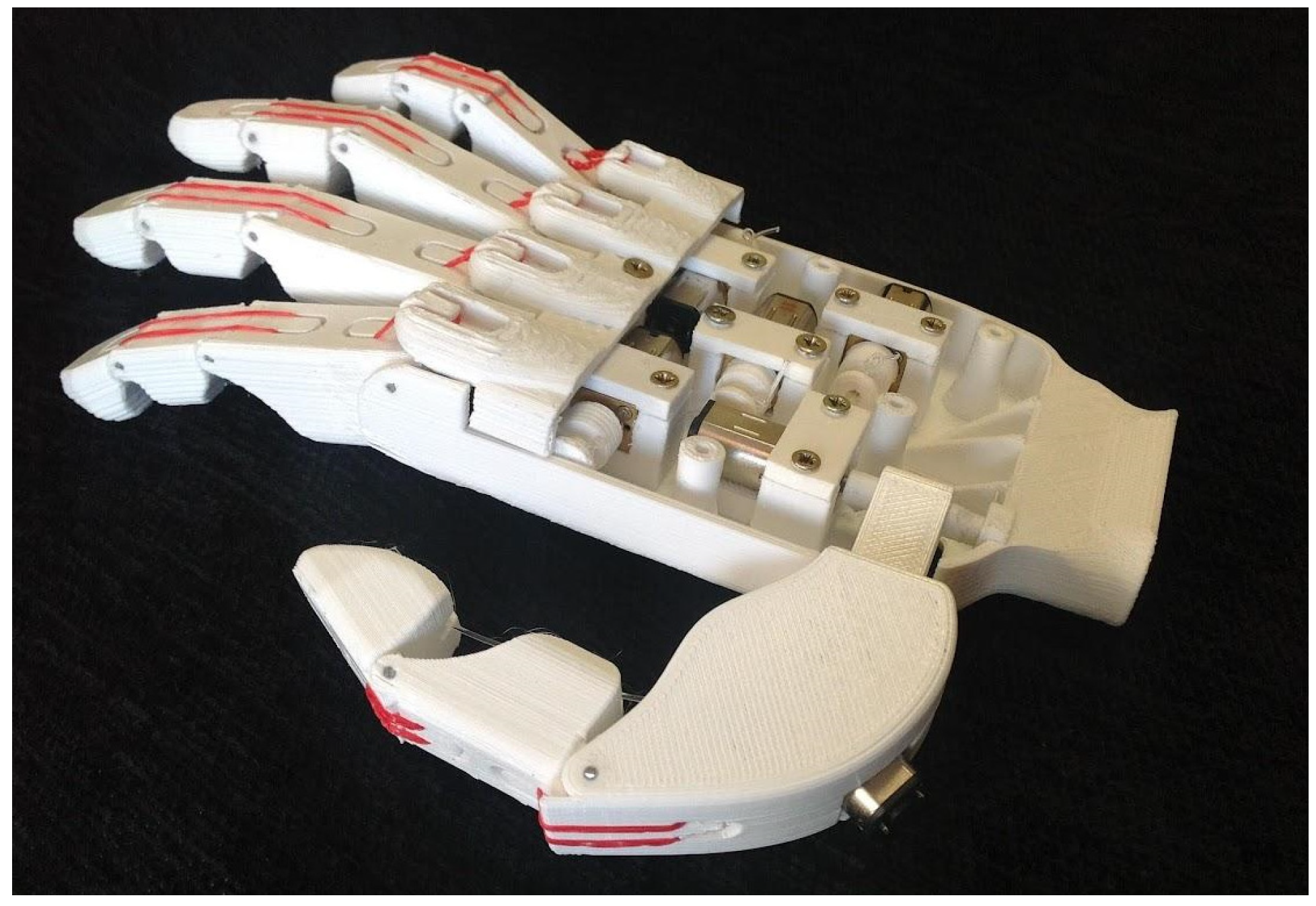
Figure 1. BRUJA Hand [18].
Mathematics 12 03236 g001
Figure 2. Controlled Auto-Regressive Integrated Moving Average (CARIMA) model [21].
Mathematics 12 03236 g002
Figure 3. Experimental results for the finger position. Up: the encoder counts, in steps, as a function of time. Down: the PWM percentage as a function of time. Steps in the encoder count are defined, such as 250 steps are equivalent to one complete turn (that is, 360 degrees).
Mathematics 12 03236 g003
Figure 4. Processed data for linear identification: incremental finger position in degrees (up) and control action in percentage (down).
Mathematics 12 03236 g004
Figure 5. Results of the identification with the model using output error. The figure shows the agreement between the modeled response (in blue) and the validation data (in gray).
Mathematics 12 03236 g005
Figure 6. Finger position evolution: set point, controlled by PID; controlled GPC; and controlling GPC with future information.
Mathematics 12 03236 g006
Figure 7. Evolution of control action: PID controlled; GPC controlled; and GPC controlled with future information.
Mathematics 12 03236 g007
Figure 8. Evolution of finger position: set point, controlled by PID; controlled GPC; and controlling GPC with future information, expanded the rise zone from t = 2 s to t = 4 s.
Mathematics 12 03236 g008
Table 1. Percentage of agreement between measured and identified models.
Identification AlgorithmId DataValidation Data
OE (output error)71.22%58.76%
ARX70.37%70.30%
PEM70.54%66.64%
N4SID70.87%65.10%
Disclaimer/Publisher’s Note: The statements, opinions and data contained in all publications are solely those of the individual author(s) and contributor(s) and not of MDPI and/or the editor(s). MDPI and/or the editor(s) disclaim responsibility for any injury to people or property resulting from any ideas, methods, instructions or products referred to in the content.