Article

Analytical Solution for Surrounding Rock Pressure of Deep-Buried Four-Hole Closely Spaced Double-Arch Tunnel

1
School of Resources and Safety Engineering, Central South University, Changsha 410006, China
2
Road & Bridge South China Engineering Co., Ltd., Zhongshan 528403, China
*
Authors to whom correspondence should be addressed.
Mathematics 2025, 13(2), 286; https://doi.org/10.3390/math13020286
Submission received: 4 December 2024 / Revised: 5 January 2025 / Accepted: 14 January 2025 / Published: 17 January 2025
(This article belongs to the Special Issue Advances in Applied Mathematics, Mechanics and Engineering)

Abstract

:
Research on the calculation method of deep-buried surrounding rock pressure is an important subject in engineering mathematics. The existing calculation methods are mainly the two-hole closely spaced tunnel, double-arch tunnel, three-hole closely spaced tunnel, and three-arch tunnel. The four-hole closely spaced double-arch tunnel has the characteristics of both the double-arch tunnel and closely spaced tunnel, and its surrounding rock pressure distribution is more complicated. In this paper, the research is carried out based on Protodyakonov’s theory and the concept of process load. The influence of the post-construction tunnel on the supporting structure of the pre-construction tunnel is also considered. The calculation model of the surrounding rock pressure of the deep-buried four-hole closely spaced double-arch tunnel is established, and the calculation formula of the surrounding rock pressure is deduced and verified. Finally, the influences of the rock column parameters, excavation procedure, tunnel span, and middle partition wall on the surrounding rock pressure are analyzed.

1. Introduction

With accelerating urbanization, tunnel construction in China has progressed significantly over the past half-century [1]. As tunnel construction demand increases, various projects face an increasing number of challenges. For example, in mountainous areas, ordinarily separated tunnels cannot be constructed due to limited available engineering space. To address this challenge, double-arch and closely spaced tunnels have been developed [2]. Tunnel surrounding rock pressure is a critical parameter guiding tunnel design, construction, and maintenance. However, as tunnel structures diversify, the distribution of surrounding rock pressure becomes more complex. Therefore, exploring methods for calculating surrounding rock pressure is essential.
Many experts have studied the surrounding rock pressure of tunnels using various methods [3,4,5]. Hu et al. [6] improved Protodyakonov’s arch theory through the finite difference method and derived a calculation method for the tunnel surrounding rock pressure affected by weak interlayer seepage. Yang et al. [7] derived an analytical solution for surrounding rock pressure by considering the effects of process load and excavation sequence. They also proposed load models for three tightly confined tunnels based on practical projects. Hu et al. [8] used the finite discrete element method to analyze the design value of tunnel surrounding rock pressure under different ground stress fields. Tong [9] analyzed data from underground projects and identified limitations in commonly used formulas for calculating surrounding rock pressure. He proposed a new model and derived a more accurate general formula, whose calculated values closely match the measured values. This confirms its reliability and applicability, guiding tunnel and underground space design and construction. Liu et al. [10] proposed a new model for calculating tunnel surrounding rock pressure in fold areas. This model is based on the method for calculating the loosening pressure of shallow tunnels surrounding rock. They also analyzed the effects of structural stress, tunnel depth, and other factors on the loosening pressure of surrounding rock.
Many experts have studied multi-arch tunnels with a complex surrounding rock pressure and small clear distances between tunnels [11,12,13,14]. Tang et al. [15] proposed a method for calculating the rock pressure in double-arch tunnels based on a limit equilibrium analysis. The method’s validity was verified through numerical analysis, which showed that the vertical pressure on the first tunnel increases as the second tunnel is excavated. This pressure is closely related to tunnel depth and the friction angle of the surrounding rock. Gao et al. [16] introduced the concept of process load into Protodyakonov’s theory, deriving an analytical solution for the surrounding rock pressure in multi-arch tunnels. The theoretical results closely match field measurements. Li et al. [17] assumed that the inner and outer rupture angles of the two tunnels are the same, and derived a theoretical formula for calculating the loosening pressure in deep-buried tunnels with close spacing. The study also discusses the effects of tunnel spacing, reinforcement methods, and excavation size on the loosening pressure. However, the theory overlooks the additional disturbance caused by the intermediate rock column. To address this, Wu et al. [18] derived a formula for the loosening pressure considering the repeated disturbance of the intermediate rock column. Their research indicates that the internal loosening pressure in the front section is higher than that in the rear section.
However, the existing methods for calculating surrounding rock pressure mainly focus on single tunnels or layouts with two tunnels. Research on multi-bore tunnel systems (such as the four-hole closely spaced double-arch tunnel) under complex geological conditions is still relatively insufficient. As a new type of structure, the four-hole closely spaced double-arch tunnel has two main characteristics: the ‘double-arch’ and the ‘compact layout’. It presents more challenges in calculating surrounding rock pressure. Some scholars have explored the theoretical surrounding rock pressure for deeply buried multi-bore tunnels [19,20,21]. A comprehensive and reliable calculation method for the surrounding rock pressure of the four-hole compact double-arch tunnel has not yet been established. Therefore, this paper aims to propose a new method for calculating the surrounding rock pressure of the four-hole closely spaced double-arch tunnel. It will also verify the method’s reliability through theoretical derivation and numerical analysis, further analyzing the key factors affecting the surrounding rock pressure.

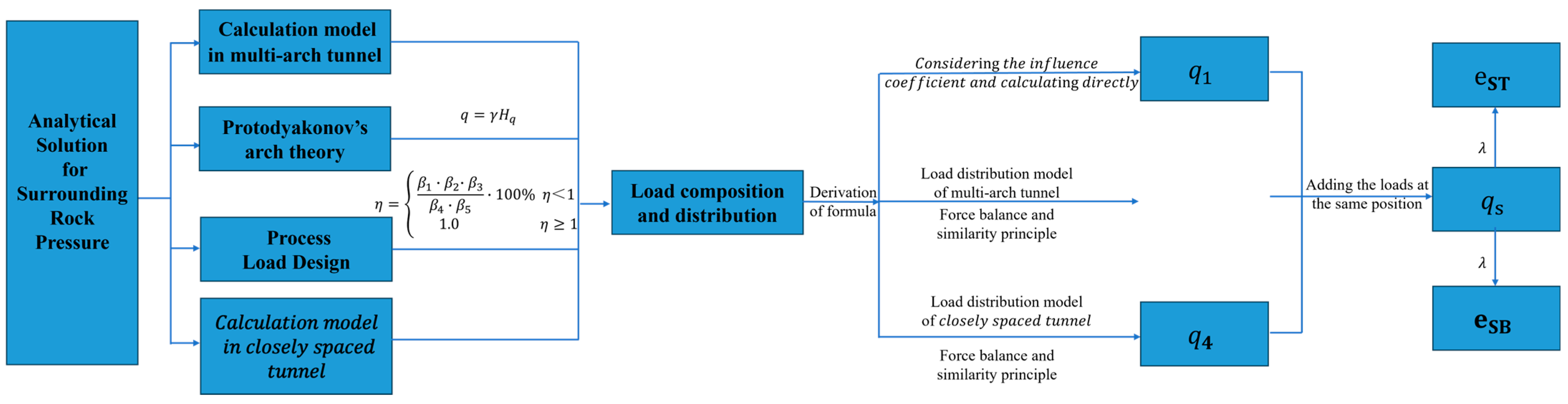
2. Theoretical Framework

This paper is based on Protodyakonov’s arch theory and the concept of process load. The analytical solution of surrounding rock pressure is derived by establishing a “continuous arch” mechanical model and a “closely spaced” mechanical model. The specific process is shown in Figure 1.
The relevant parameters in the process of formula derivation are shown in Table A1.

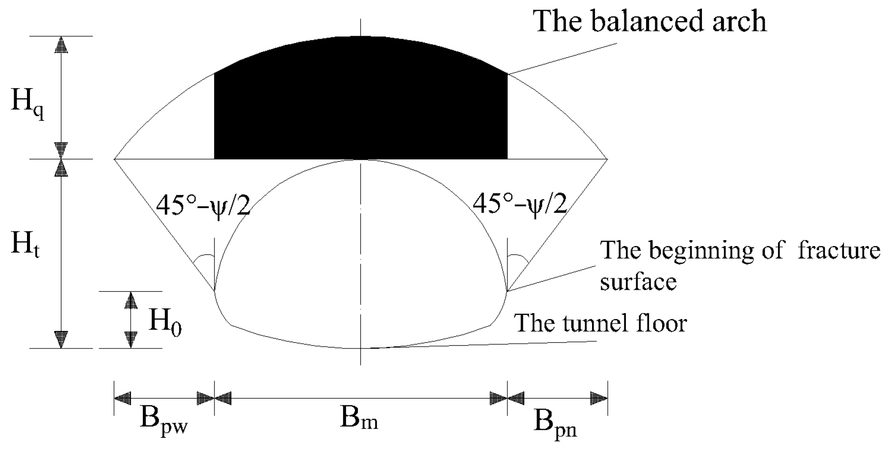
2.1. Calculation Method of Surrounding Rock Pressure of Protodyakonov’s Arch

Protodyakonov’s arch theory [6] is mainly aimed at the loose surrounding rock. It assumes a stable balanced arch will be formed above the tunnel after excavation. The rock and soil body above the equilibrium arch will not be disturbed. The rock and soil body below the equilibrium arch will be broken and act on the support in the way of self-weight [22], as shown in Figure 2.
The formula for calculating the surrounding rock pressure of Protodyakonov’s arch theory is as follows:
q = γ H q
H q = B m 2 f
B q = B t + 2 ( H t H 0 ) t a n 45 ° φ c 2
where q is the vertical surrounding rock pressure, γ is the weight of the surrounding rock, H q is the vertical height of the balanced arch, B m is the horizontal width of the balanced arch, B t is the excavation span of the tunnel, f is the firmness coefficient of surrounding rock, mainly related to the saturation uniaxial compressive strength of surrounding rock, generally R C /10, H t is the excavation height of the tunnel, and H 0 is the vertical height from the tunnel floor to the beginning of the fracture surface.

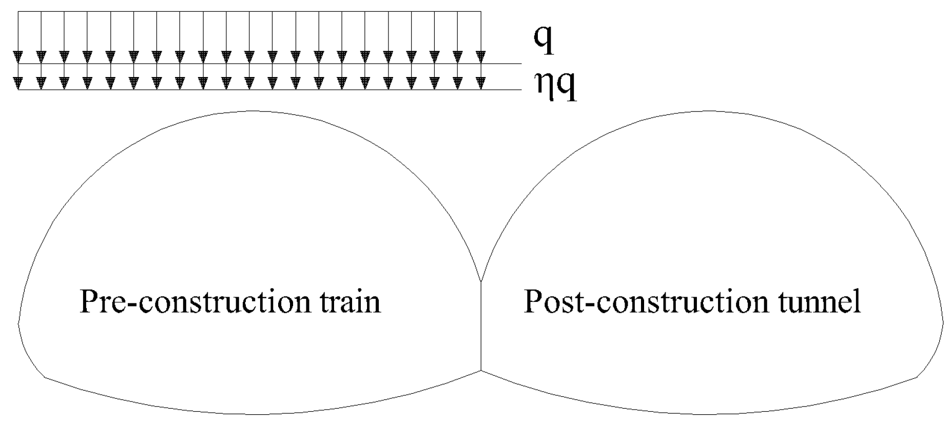
2.2. Process Load Design

Due to the construction of the post-construction tunnel, the concept of process load design [16,23] holds that the loose earth pressure above the pre-construction tunnel will increase. The specific increase proportion is reflected by the influence coefficient η . The calculation results of η are related to many factors such as tunnel spacing, rear tunnel height span ratio, front tunnel support, and surrounding rock grade. The process load concept can show the bias effect of multiple tunnels close to each other. It is more suitable for deep-buried four-hole double-line parallel closely spaced multi-arch tunnels.
For closely spaced tunnels and multi-arch tunnels, the common excavation methods include the guide tunnel method and the middle guide tunnel method. The structure of the pre-construction tunnel is affected by the post-construction tunnel [24,25]. The inner rear guide tunnel will also cause disturbance to the first guide tunnel in the process of excavation of a single main tunnel. However, compared with the disturbance degree between the main tunnels, the latter has a more significant influence on the final surrounding rock pressure of the whole four-hole tunnel [26]. To highlight the key points, only the interaction between the main tunnel is considered in the theoretical derivation process, and the interaction between the internal small guide tunnel is not considered. In this section, the influence coefficient η is introduced to quantify the influence degree between adjacent main tunnels, as shown in Figure 3.
When η > 1 , it indicates that the post-construction tunnel increases the loosening load of the pre-construction tunnel. When η = 1 , it means that the construction of the post-construction tunnel will not cause disturbance to the pre-construction tunnel. The formula for calculating η is as follows [27]:
η = β 1 · β 2 · β 3 β 4 · β 5 · 100 %       β 1 β 2 β 3 β 4 β 5                           1.0                                       β 1 β 2 β 3 < β 4 β 5
where the values of β 1 to β 5 are, respectively, given by the tunnel spacing, height span ratio of the post-construction tunnel, geological recommendation, supporting condition of the preceding tunnel, and grade of the surrounding rock. The value ranges of the above five influencing indicators are shown in Table 1, Table 2, Table 3, Table 4 and Table 5 [28].

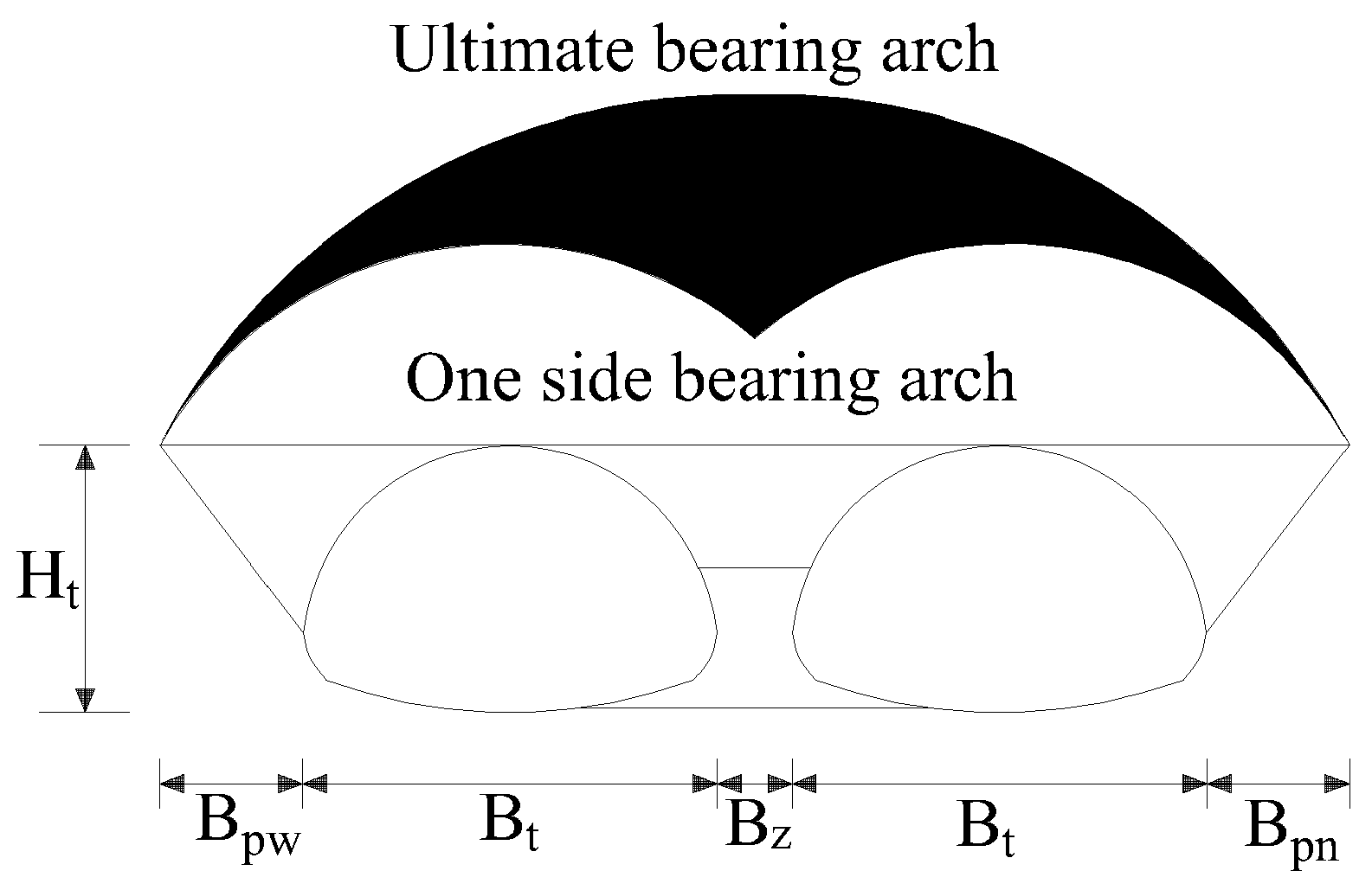
2.3. The Calculation Model of Surrounding Rock Pressure

The multi-arch tunnel generally needs to excavate the main tunnel after the advanced construction of the middle guide tunnel is completed. For the four-hole double-line parallel closely spaced multi-arch tunnel, it is necessary to excavate the main tunnel after the construction of the two middle guide tunnels is completed. After the completion of the construction of all tunnels, the surrounding rock pressure distribution presents a four-hole and closely spaced continuous arch pattern. This pattern includes the two mechanical behaviors of “continuous arch” and “closely spaced”.

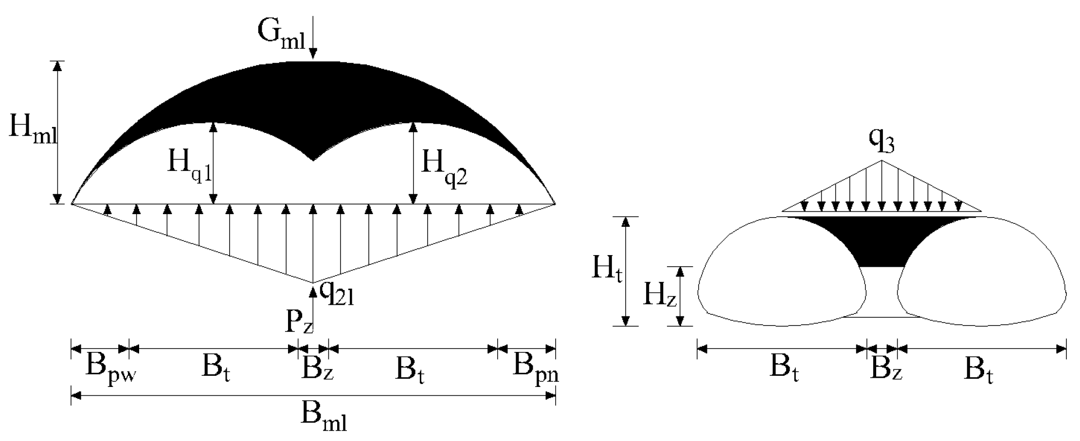
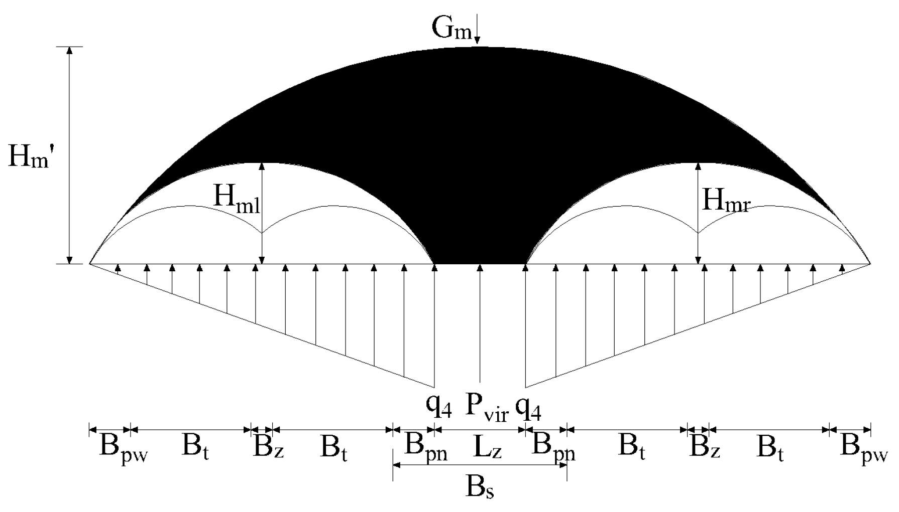
2.3.1. Mechanical Behavior of Continuous Arch

For the left and right lines, it can be regarded as the calculation model of the surrounding rock pressure of two double-arch tunnels (as shown in Figure 4). The pressure of the surrounding rock is related to the formation of the composite arch. The middle partition wall has a certain bearing effect and can hinder the formation of a composite arch [29]. The details are as follows:
(1) The middle partition wall is backfilled in time and has excellent stability. The double-arch tunnel can be regarded as two independent single-hole tunnels, which only form their single-hole bearing arches on the left and right;
(2) The middle partition wall backfill is not timely, and the stability is very poor. The left and right tunnels form a large composite arch together. The surrounding rock pressure borne by the double-arch tunnel is the loose earth pressure of the whole composite arch;
(3) Generally speaking, the middle partition wall is between two states: (1) and (2). The middle partition wall inhibits the formation of the composite arch to a certain extent but does not completely inhibit it.

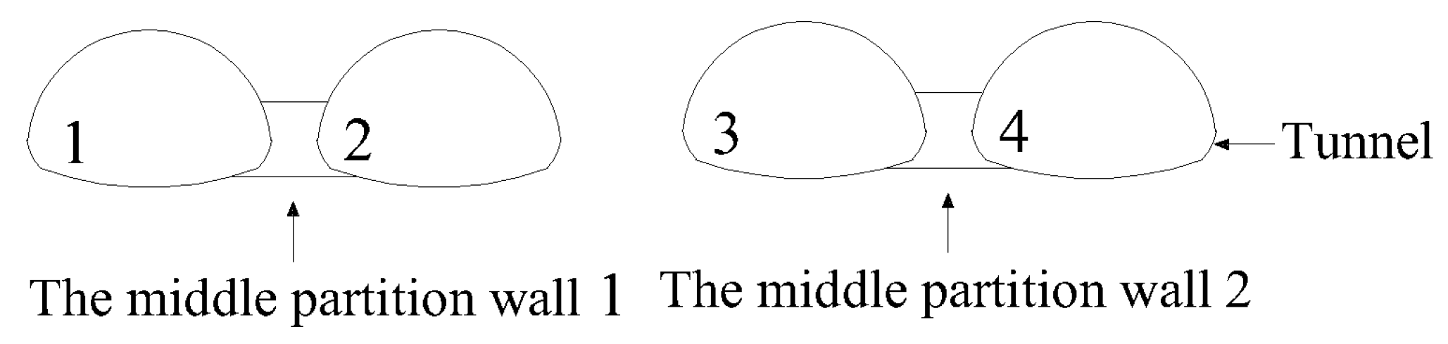
2.3.2. Mechanical Behavior of Closely Spaced

The left and right multi-arch tunnels can be regarded as two large-section tunnels. The mechanical behavior of “closely spaced” is displayed on the whole, as shown in Figure 5. For the closely spaced tunnel, the middle rock pillar has a certain bearing effect. It is related to its width, strength, and construction method [30]. It can hinder the formation of composite arches, as follows [31]:
(1) The strength of the middle rock pillar is very low and the width is very small. The whole four-hole double-line parallel closely spaced multi-arch tunnel will form a four-hole compound arch on top. The surrounding rock pressure should be calculated according to the loose earth pressure in the four-hole composite arch;
(2) The middle rock pillar has very high strength and great width. The calculation model of the surrounding rock pressure of the double-arch tunnel is formed only on the left and right lines;
(3) Generally speaking, the middle rock pillar is between (1) and (2). It has a certain inhibitory effect on the formation of the whole four-hole large composite arch.

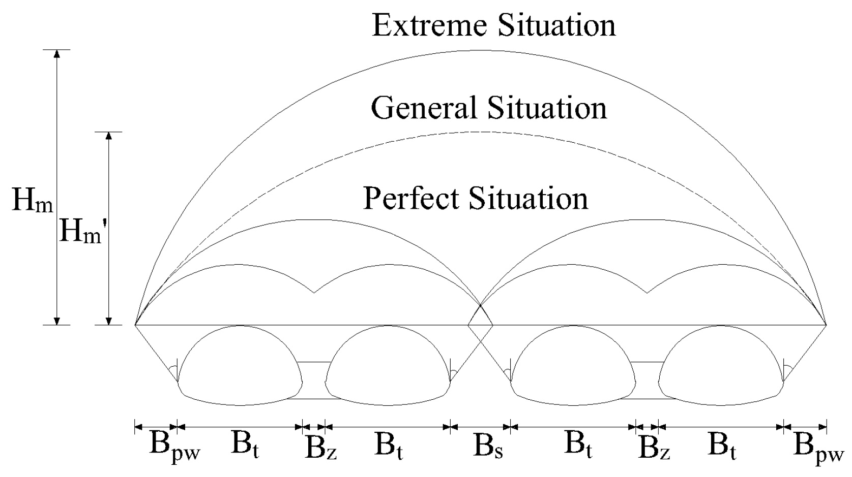
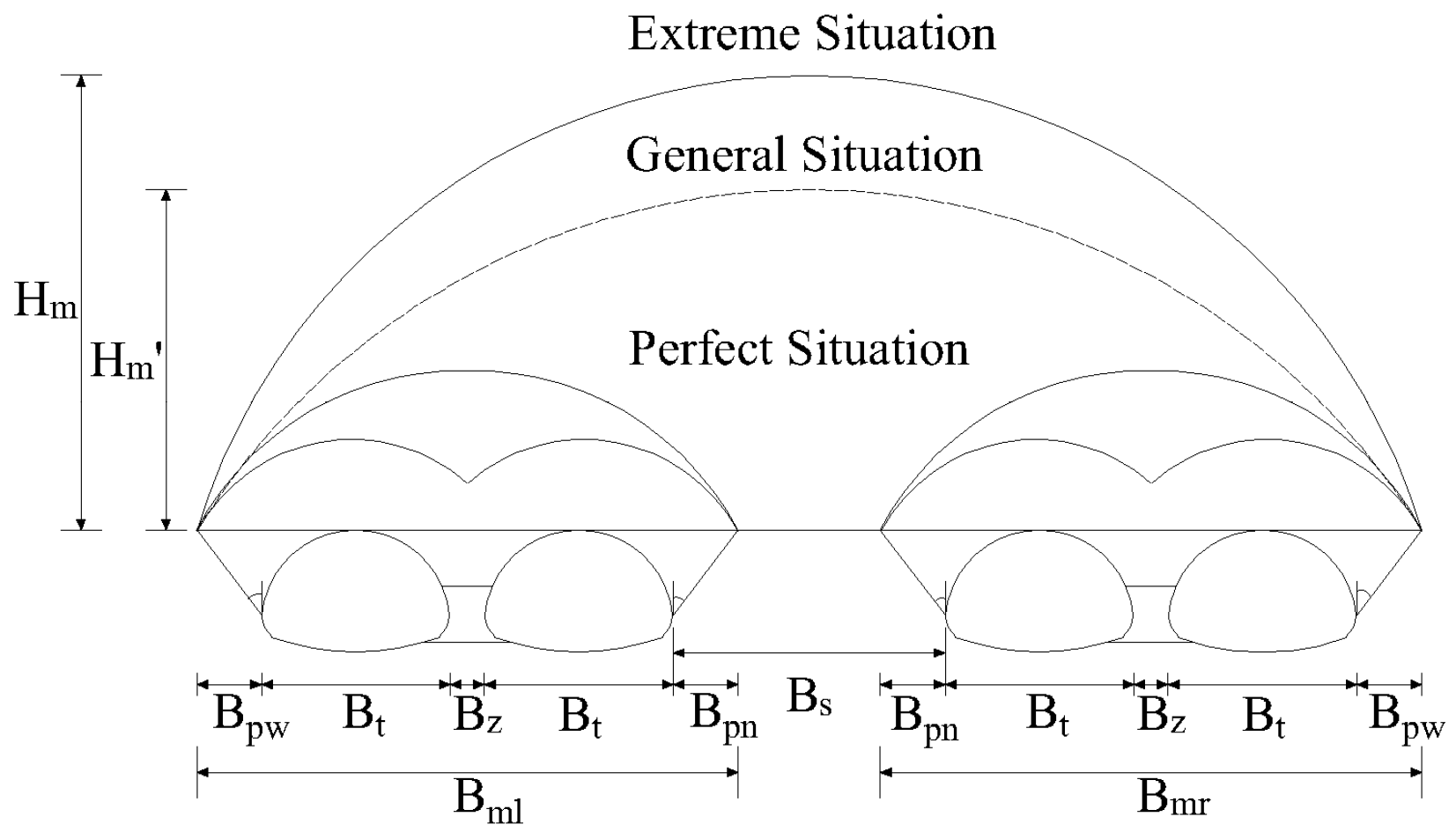
2.3.3. Models and Assumptions

In summary, the four-hole double-line parallel closely spaced multi-arch tunnel presents the closely spaced tunnel mode in general. The multi-arch mode is shown in the left and right parts. Therefore, two extended models of Protodyakonov’s arch theory of the deep-buried four-hole double-line parallel closely spaced multi-arch tunnel can be established. Figure 6 shows the calculation model 1. In this model, the inner sliding planes of the tunnel intersect. The middle rock pillar does not have the bearing capacity, which only inhibits the formation of the composite arch. Figure 7 shows the calculation model 2. In this model, the inner sliding surfaces of the tunnel do not intersect. The middle rock pillar not only inhibits the formation of the composite arch but also has a bearing effect. These two calculation models can be divided into three working conditions:
(1) The stability of the middle rock pillar is very poor, and the compound arch with a four-hole limit is formed above it;
(2) The stability of the middle rock pillar is very good, and only the left and right lines form their double arch compound arch;
(3) In general, the bearing arch is between the four-hole limit composite arch and the double-hole composite arch.
Figure 6. Calculation model 1 when inner fracture surfaces intersect.
Mathematics 13 00286 g006
Figure 7. Calculation model 2 when the inner fracture plane is not intersected.
Mathematics 13 00286 g007
Where B t is the excavation horizontal span of tunnel 1 to tunnel 4, respectively, H t is the excavation vertical height of tunnel 1–tunnel 4, B p w is the horizontal projection width of the outer fracture surface, B p n is the horizontal projection width of the inner fracture surface, B z is the design width of the middle partition wall, and B s is the width of the middle rock pillar. B q 1 = B t + B p w + 0.5 B z ; B q 2 = B t + B p n + 0.5 B z ; B q 3 = B t + B p n + 0.5 B z ; B q 4 = B t + B p w + 0.5 B z ; B m l = B q 1 + B q 2 ; B m r = B q 3 + B q 4 ; B m = 4 B t + 2 B p w + B s , H m is the height of the four-hole composite arch, and H m is the height of the four-hole composite arch under extremely good conditions.
Both the single arch and composite arch satisfy Protodyakonov’s arch theory, and the corresponding load height of Protodyakonov’s arch is as follows:
H q i = B q i 2 f
H m l = B m l 2 f
H m r = B m r 2 f
H m = B m 2 f
where H q i ( i = 1 , 2 , 3 , 4 ) is the load height of the single bearing arch of tunnel 1 to tunnel 4, and H m l and H m r are the load heights of the composite bearing arch of the left line and the right line with double holes. The other symbols have the same meanings as before.

3. Calculation Method

3.1. Assumption of Surrounding Rock Pressure Calculation

For the sake of the following description, the four main tunnel holes from left to right are named tunnel 1, tunnel 2, tunnel 3, and tunnel 4, respectively. The middle partition wall is named middle partition wall 1 and middle partition wall 2 from left to right, respectively, as shown in Figure 8.
Considering the influence of multiple tunnels, closely spaced, and multiple arches, the surrounding rock pressure is difficult to obtain accurately. Therefore, certain simplifications and assumptions need to be made for the deep-buried four-hole double-line parallel closely spaced multi-arch tunnel, as follows:
(1) Load Considerations for Single and Composite Arches: the single arch loads (tunnel 1 to tunnel 4) and the composite arch loads for the left and right double arches, as well as the overall composite arch load for all four tunnels, need to be considered;
(2) Impact of Post-Construction Tunnel on Pre-Construction Tunnel: The construction of the post-construction tunnel increases the loosening load on the pre-construction tunnel, thus the surrounding rock pressure is corrected based on the process load design concept. The mutual disturbance between tunnel 1 and tunnel 3, and between tunnel 2 and tunnel 4, is ignored due to the distance between them;
(3) Neglect of Pressure Arch from Middle Guiding Tunnel: The construction of the middle guiding tunnel in a multi-arch tunnel generally has a minimal impact due to its small section and timely support, so the pressure arch formed by the middle guiding tunnel is neglected. A mutual disturbance between the two middle guiding tunnels is also ignored due to their distance;
(4) H m = ξ H m . Height Correction of Four-Hole Composite Arch: The height of the four-hole composite arch is corrected by an additional load correction factor ξ ( 0 ξ 1 ). When the intermediate rock pillar does not participate in the force ( L z = 0 ), it helps to inhibit surrounding rock deformation;
(5) Symmetry and Biased Pressure State: The four tunnels are assumed to be of the same size and symmetric about the centerline. When one tunnel is excavated but the other is not, the middle partition wall experiences a biased pressure state [29,30], which is alleviated after the excavation of both tunnels. To reduce the partial pressure on the middle partition wall, one side of the multi-arch tunnel should be constructed first, followed by the other side. As a result, there are four construction sequences for the four-hole double-line parallel multi-arch tunnels under deeply buried conditions, as shown in Table 6.
The specific construction process of construction sequence 1 in Table 6 is as follows:
Firstly, tunnel 1 is excavated and supported; then, tunnel 2 is excavated and supported; then, tunnel 3 is excavated and supported; and finally, tunnel 4 is excavated and supported. The same applies to the other sequences.

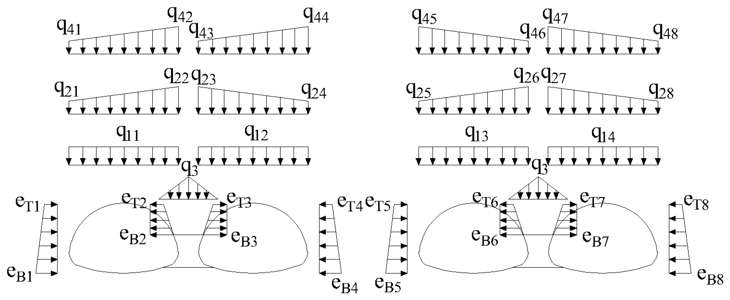
3.2. The Calculation Formula of Surrounding Rock Pressure

The surrounding rock pressure formed in sequence 1 to sequence 4 is generally similar. The difference is mainly reflected in the influence of the process load on the basic surrounding rock pressure of each tunnel. In this section, the calculation formula of the surrounding rock pressure is derived by taking sequence 1 as an example.

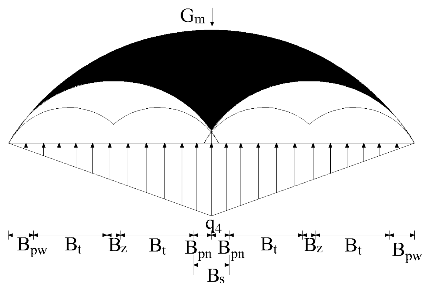
3.2.1. Load Distribution

The load distribution of the deep-buried four-hole double-line parallel closely spaced multi-arch tunnel is shown in Figure 9.
The surrounding rock pressure includes the vertical surrounding rock pressure and the horizontal surrounding rock pressure. The vertical surrounding rock pressure can be regarded as three parts:
(1) The basic surrounding rock pressure q 1 is the load provided by the rock and soil body under the arch of the single tunnel. q 1 is assumed to be a uniform load;
(2) The additional surrounding rock pressure q 2 of the double hole. q 2 is the load of the loose rock mass under the bearing arch formed by the double-arch tunnel minus the basic loose rock mass and the pre-supporting earth pressure on the top of the middle partition wall. q 2 is assumed to be a linear distribution load;
(3) The additional surrounding rock pressure   q 4 of the four holes. q 4 is the load of the loose rock mass under the bearing arch formed by the whole four-hole tunnel minus the load of the loose soil pressure under the bearing arch of the double arch. q 4 is assumed to be a linear distribution load.
In addition, there is a certain loose earth pressure q 3 above the middle partition wall. q 3 is assumed to be the pre-distributed load. The horizontal surrounding rock pressure is the vertical surrounding rock pressure multiplied by the upper side pressure coefficient.
The following parameters are defined:
(1) q 11 , q 12 , q 13 , and q 14 are the basic surrounding rock pressures from tunnel 1 to tunnel 4, respectively;
(2) q 21 , q 22 , q 23 , and q 24 are the vertical surrounding rock pressures of the additional surrounding rock pressure q 2 L at the side wall of tunnel 1 and 2, respectively;
(3) q 25 , q 26 , q 27 , and q 28 are the vertical surrounding rock pressures of the additional surrounding rock pressure q 2 R at the side wall of tunnel 3 and 4, respectively;
(4) q 41 , q 42 , …, q 48 are the vertical surrounding rock pressures of the additional surrounding rock pressure at the side wall of tunnel 1 to tunnel 4 of the four-hole double-line parallel closely spaced continuous arch tunnel;
(5) e 1 T , e 1 B , e 2 T , e 2 B e 8 T , and e 8 B are the top and bottom horizontal surrounding rock pressures on both sides of tunnel 1–tunnel 4;
(6) q 3 is the maximum pressure of the loose earth above the middle partition wall.
The basic surrounding rock pressure refers to the initial pressure release in the surrounding rock when a tunnel is excavated and loses support, marking the first adjustment in the rock’s stress field. This pressure is crucial for the subsequent support design and affects the rock’s stability and deformation. The additional surrounding rock pressure (including pressures in double-arch and four-arch tunnels) results from pressure redistribution caused by multiple tunnel excavations. This pressure is closely related to the basic surrounding rock pressure, and as the number of tunnels increases, the pressure complexity and stress magnitude also increase.

3.2.2. Load Formula Derivation

(1) Basic surrounding rock pressure q 1 .
When tunnel 1 is excavated, the basic surrounding rock pressure can be calculated according to the theory of the single-hole Protodyakonov’s arch. Due to the close proximity of tunnel 1 and tunnel 2, the construction of tunnel 2 will disturb the surrounding rock above tunnel 1. It is necessary to consider the process load factor η 12 . Similarly, tunnel 3 will disturb the surrounding rock above tunnel 2, and the process load factor is η 23 . Tunnel 4 will disturb the surrounding rock above tunnel 3, and the process load factor is η 34 . Before the construction of tunnel 3, tunnel 1, tunnel 2, and the rock pillar in the middle have generally been supported and reinforced. Tunnel 1 and tunnel 3 are far apart. Therefore, the disturbance of tunnel 3 to tunnel 1 is not considered. Similarly, the disturbance of tunnel 4 to tunnel 2 is not considered. The basic surrounding rock pressure calculation formula of tunnel 1 to tunnel 4 under sequence 1 is as follows:
q 11 = η 12 γ h q 1
q 12 = η 23 γ h q 2
q 13 = η 34 γ h q 3
q 14 = γ h q 4
(2) Additional pressure on surrounding rock of double-arch tunnel q 2 .
For the left and right lines, they will form their double-arch compound arch. The form of this load is assumed to be a triangular load. The stable state of the middle partition wall directly affects the additional surrounding rock pressure of the double-arch tunnel. In addition, there is a certain loose load q 3 between the top of the middle partition wall and the top of the two tunnels. Its load form is also assumed to be a triangular load. The load distribution mode of the double-arch tunnel is shown in Figure 10.
Taking the left line as an example, the mass force of the rock and soil in the shadow part under deep burial is denoted as G m L , which can be obtained by Equation (13):
G m l = 2 3 γ B m l H m l η 12 B q 1 H q 1 η 23 B q 2 H q 2
According to the balance of G m l and vertical supporting force, it can obtain the following:
G m l = 1 2 B m l q 2 l + P z
q 2 l = 4 3 γ B m l H m l η 12 B q 1 H q 1 η 23 B q 2 H q 2 2 P z B m l
The supporting force   P z   of the middle partition wall is expressed as follows:
P z = q z B z
where q z is mainly restricted by the loading capacity of the rock mass at the top of the middle partition wall, the additional weight of the rock mass under the double-hole composite arch under the limit condition, and the compressive capacity of the concrete, q z = m i n ( p c , G m l / B z , p s ) . Due to the strong compressive capacity of concrete, p c is generally not calculated. R s is the design compressive strength of the rock mass at the top of the partition wall in the left line, and K is the safety factor, usually 2 [29].
It is assumed that the additional load distribution of the left line double-arch tunnel is triangular. The vertical surrounding rock pressure of q 2 L at the side wall of tunnel 1 and tunnel 2 can be obtained by the triangular similarity ratio:
q 21 = B p w B q 1 · q 2 l
q 22 = B p w + B t B q 1 · q 2 l
q 23 = B p n + B t B q 2 · q 2 l
q 24 = B p n B q 2 · q 2 l
Similarly, for the right line, you can obtain q 2 R :
q 2 r = 4 3 γ B m r H m r η 34 B q 3 H q 3 B q 4 H q 4 2 P z B m r
According to the triangle similarity ratio, the vertical surrounding rock pressure of q 2 R at the side wall of tunnel 3 and tunnel 4 can be obtained as follows:
q 25 = B p n B q 3 · q 2 r
q 26 = B p n + B t B q 3 · q 2 r
q 27 = B p w + B t B q 4 · q 2 r
q 28 = B p w B q 4 · q 2 r
B p w , B p n :
B p w = B p n = ( H t H o ) t a n θ
where θ is the angle between the fracture plane and the horizontal direction.
(3) The maximum pressure of the loose surrounding rock at the top of the middle partition wall q 3 :
q 3 = γ H 3
where H 3 = H t H z , H z is the height of the middle partition wall.
(4) Additional four-hole closely spaced continuous arch surrounding rock pressure q 4 .
For the whole span, a four-hole composite arch containing the dual characteristics of “continuous arch” and “closely spaced” will be formed. The form of load formed by it is also assumed to be a triangular load.
The effective support width of the rock pillar is defined as L z , and the calculation formula is as follows:
L z = B s 2 ( H t H o ) t a n θ
According to whether L z is greater than 0, we can judge whether the middle rock pillar plays a bearing role on the loose rock and soil body above. Then the vertical surrounding rock pressure of the four-hole double-line parallel closely spaced multi-arch tunnel can be discussed in the following two cases, as shown in Figure 11 and Figure 12, respectively.
When L z > 0 , the unexcavated rock mass in the middle can restrain the deformation of the surrounding rock and reduce the height of a “four-hole composite arch”. At the same time, it also participates in bearing the pressure of the rock and soil mass in the shadow. The rock mass force G M of the shaded part can be obtained by the following formula:
G m = 2 3 γ B m H m B m l H m l B m R H m r
According to calculation model 1 and the force balance, it can be obtained as follows:
G m = P v i r + 0.5 ( B m r + B m l ) q 4
q 4 = 4 3 γ B m H m B m l H m l B m r H m r 2 P v i r B m r + B m l ,         q 4 > 0 q 4 = 0 ,     q 4 0
where P v i r = q v i r L z , q v i r is the compressive strength of the unexcavated rock mass in the middle, which is determined by the following two constraints:
(a) q v i r R p / K , R p is the compressive strength of the intermediate rock pillar, and K is the safety factor, generally 2;
(b) q v i r G m / L z , the upper load borne by the intermediate rock pillar, cannot exceed the weight of the entire additional bearing arch.
Therefore, q v i r should take the smaller value of the two, that is
q v i r = m i n R p K , G m L z
When L z 0 , it means that the middle rock pillar can only weaken the deformation of the surrounding rock and reduce the height of the composite arch. According to calculation model 2, it can be obtained as follows:
2 3 γ B m H m B m l H m l B m r H m r = ( B m r + B m l ) q 4
q 4 = 4 3 γ B m H m B m l B m r B m r + B m l ,   q 4 > 0 q 4 = 0 ,   q 4 0
The additional surrounding rock pressure q 4 at the side wall of tunnel 1 to tunnel 4 is q 41 , q 42 , …, q 48 . For the above two cases, according to the corresponding proportional relationship, it can be obtained as follows:
q 41 = B p w B m l · q 4 q 42 = B p w + B t B m l · q 4 q 43 = B p w + B t + B z B m l · q 4 ,   q 44 = B p w + 2 B t + B z B m l · q 4 q 45 = B p w + 2 B t + B z B m r · q 4 q 46 = B p w + B t + B z B m r · q 4 q 47 = B p w + B t B m r · q 4 q 48 = B p w B m r · q 4

3.2.3. Final Surrounding Rock Pressure

By adding the basic surrounding rock pressure, the additional surrounding rock pressure of the double-hole continuous arch, the surrounding rock pressure at the top of the middle partition wall, and the additional surrounding rock pressure of the four-hole closely spaced continuous arch, the final vertical surrounding rock pressure q S can be obtained as follows:
q S 1 = q 11 + q 21 + q 41 q S 2 = q 11 + q 22 + q 3 + q 42 q S 3 = q 12 + q 23 + q 3 + q 43 q S 4 = q 12 + q 24 + q 44 q S 5 = q 13 + q 25 + q 45 q S 6 = q 13 + q 26 + q 3 + q 46 q S 7 = q 14 + q 27 + q 3 + q 47 q S 8 = q 14 + q 28 + q 48
The top vertical surrounding rock pressure is multiplied by the side pressure coefficient λ to obtain the final horizontal surrounding rock pressure e S T at the top:
e S T 1 = q S 1 · λ e S T 2 = q S 2 · λ e S T 3 = q S 3 · λ e S T 4 = q S 4 · λ e S T 5 = q S 5 · λ e S T 6 = q S 6 · λ e S T 7 = q S 7 · λ e S T 8 = q S 8 · λ
The vertical surrounding rock pressure at the bottom fracture surface is multiplied by the lateral pressure coefficient λ to obtain the final horizontal surrounding rock pressure e S B at the bottom:
e S B 1 = q S 1 + γ ( H t H 0 ) · λ e S B 2 = q S 2 + γ ( H t H z ) · λ e S B 3 = q S 3 + γ ( H t H z ) · λ e S B 4 = q S 4 + γ ( H t H 0 ) · λ e S B 5 = q S 5 + γ ( H t H 0 ) · λ   e S B 6 = q S 6 + γ ( H t H z ) · λ e S B 7 = q S 7 + γ ( H t H z ) · λ e S B 8 = q S 8 + γ ( H t H z ) · λ
where λ is the lateral pressure coefficient, and according to Rankine’s earth pressure theory, λ = t a n 2 ( 45 ° φ c / 2 ) is preferred. The other symbols have the same meaning as before.

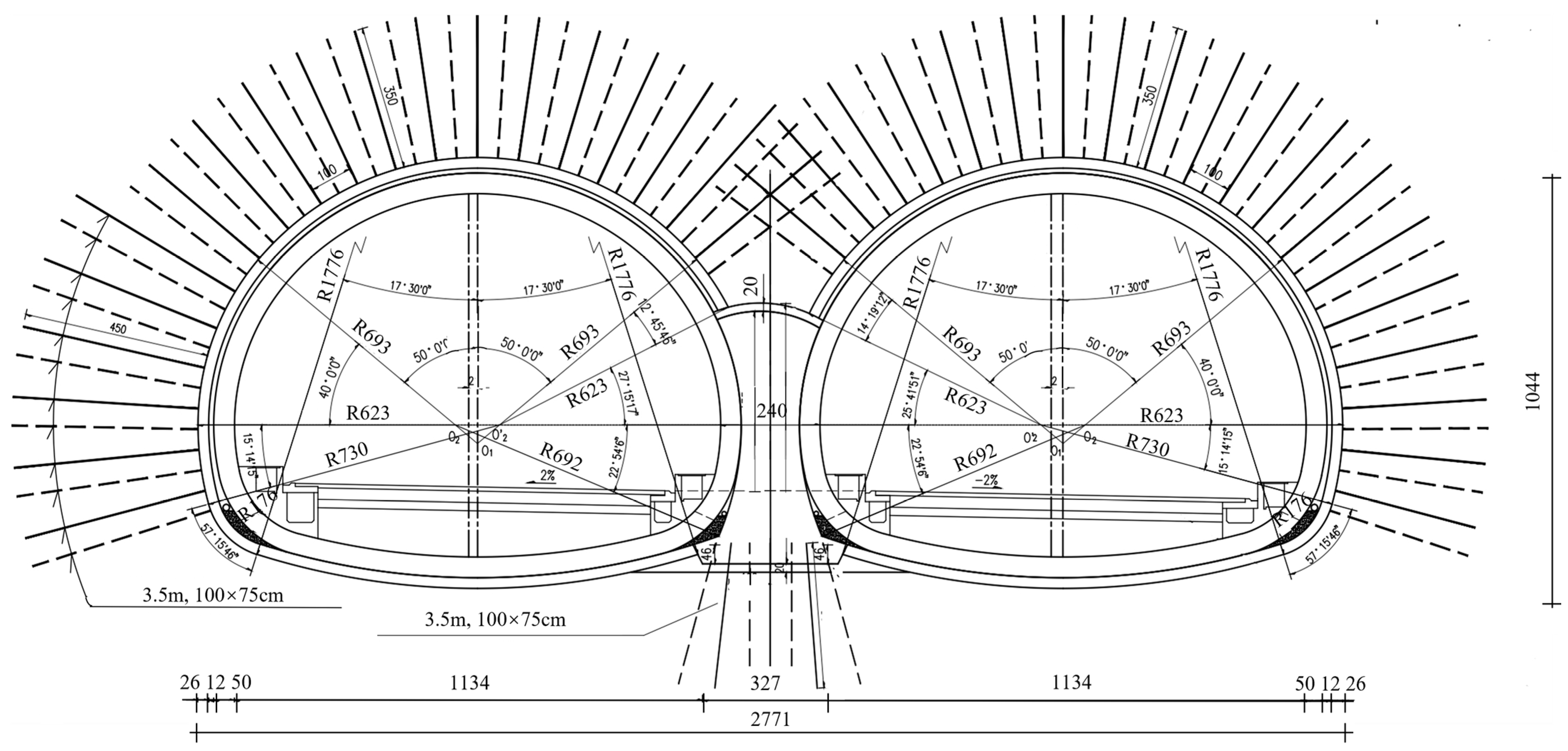
4. Result Verification

4.1. Calculation of Rock Pressure

This section takes the left line (tunnel 1 and tunnel 2) as an example. This section is based on the calculation method derived in this paper, the standard algorithm [20] and the algorithm derived by Li et al. [29]. It analyzes and discusses the changes in the vertical surrounding rock pressure under the action of the middle rock pillar and excavation span in the closely spaced multi-arch tunnel. The rationality and correctness of the derived theory are verified by comparison.
This section relies on the Wengcun Tunnel as the engineering background. It is a four-hole closely spaced double-arch tunnel from Guilin to Liuzhou. The left line is 485 m long and the maximum buried depth is about 92 m. The left line mileage stakes are ZK1182 + 340 − ZK1182 + 825. The right line is 426.6 m long and the maximum buried depth is 79 m. The milepost number of the right line is YK1182 + 410 − YK1182 + 836.6. The general situation of the tunnel and the cross section of the single-line multi-arch tunnel are shown in Figure 13.
The surrounding rock of the calculation section is mainly Grade V. The parameters are selected as follows:
The total span of the multi-arch tunnel is about 27 m, the excavation span B t of the single-hole tunnel is 12.5 m, the height H t is 10 m, and the width B z of the middle partition wall is 2 m. The width B z of the middle rock pillar is 18 m. According to the survey data provided by the site and the “code for design of highway tunnels (JTG3370.1-2018) [20]”, the calculation parameters of the fifth-level surrounding rock can be evaluated. The surrounding rock weight γ = 19   k N / m 3 , the saturated uniaxial compressive strength of rock R c = 10   M P a , the cohesion force c = 10   M P a , the fracture plane angle is 25°, the calculated friction angle φ c = 45 ° , and the compressive strength of the middle rock pillar R p = 1000   k P a . The design compressive strength of the rock mass at the top of the middle partition wall R s = 600   k P a , the side pressure coefficient λ = 0.172 , the firmness coefficient f = 1 , and the safety factor K = 2 .
The excavation sequence of the tunnel is as follows: tunnel 1, tunnel 2, tunnel 3, and tunnel 4. The value of the process load influence coefficient η is determined according to the condition of the engineering tunnel. Tunnel 1 has the same η as tunnel 3. Therefore, only η 12 and η 23 are required, as shown in the Table 7 and Table 8.
Since 0.87 < 1, η 23 = 1 . After calculation, the surrounding rock pressure is shown in Table 9.

4.2. Verification of Theoretical Formulas Based on the Width of Rock Pillars

According to the calculation method derived in this paper, the standard algorithm and the algorithm derived by Li et al. [29] are used to calculate the surrounding rock pressure successively. As shown in Figure 14, the dot plot represents the vertical surrounding rock pressure obtained by different algorithms. The relative error of the surrounding rock pressure obtained by the proposed algorithm and the standard algorithm is shown in the bar chart. The relative error is composed of the process load, four-hole compound load, and algorithm limitation.
Since the calculation variable is the width of the middle rock pillar, it is necessary to regard the left and right line connecting the supply tunnel as a large-section tunnel, respectively. On the whole, the left and right line tunnel is regarded as a small clear distance tunnel.
As shown in Figure 14, other algorithms do not consider the influence of the process load and four-hole composite load. The obtained surrounding rock pressure has little difference. Because of the mechanical behavior of closely spaced, the tunnel will be affected by the compound load of four holes when the width of the middle rock column is small. The surrounding rock pressure of tunnel 1 is 50% higher than that of the standard algorithm. Because tunnel 2 is closer to the four-hole composite center, the impact is greater. The surrounding rock pressure of tunnel 2 is 77% higher than that of the standard algorithm.
When the width of the rock column reaches 27 m, the difference in the surrounding rock pressure is small. This is because the width of the middle rock pillar is large, and the four-hole tunnel is not affected by the four-hole composite load. At this time, the left and right two-line tunnels are common multi-arch tunnels. Due to the influence of the process load, the surrounding rock pressure of tunnel 1 is about 16% higher than that of the standard algorithm.
It can be seen from η 23 = 1 that the construction of tunnel 3 does not affect tunnel 2. The distance between the vertical surrounding rock pressure of tunnel 2 and that of the standard algorithm is less than 3%. The results show that the relative error caused by the algorithm limitation is less than 3%. To sum up, the derivation method in this paper is reliable.

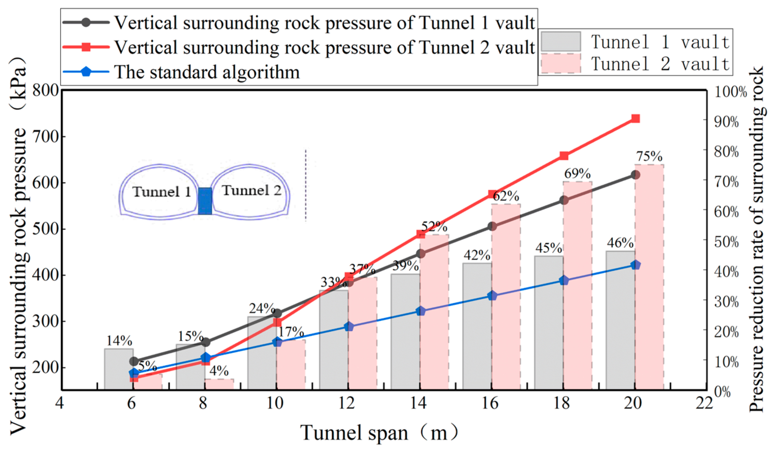
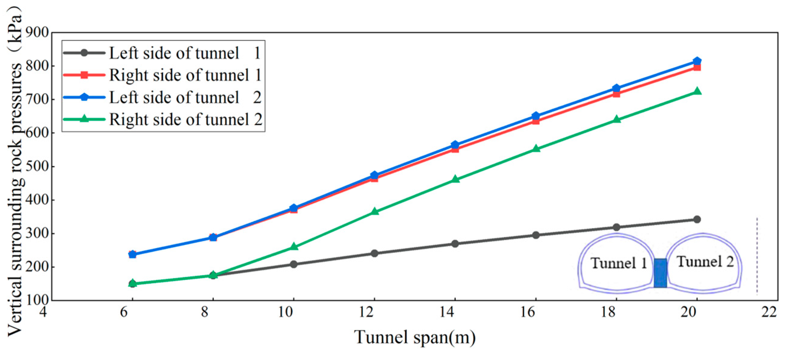
4.3. Verification of Theoretical Formulas Under Different Tunnel Excavation Spans

The vertical surrounding rock pressure and relative error of the arch roof obtained by different algorithms under different tunnel spans are shown in Figure 15.
When the excavation span is 6 m–8 m, the calculated pressure difference of the surrounding rock is small. This is because the tunnel excavation span is small, and the four-hole tunnel is not affected by the combined load of four holes. This shows that the left and right two-line tunnel is a common multi-arch tunnel. Due to the influence of the process load, the vertical surrounding rock pressure of tunnel 1 is about 15% higher than that obtained by the standard algorithm. The construction of tunnel 3 does not influence the surrounding rock pressure of tunnel 2. The distance between the vertical surrounding rock pressure of tunnel 2 and that obtained by the standard algorithm is less than 5%. This shows that the relative error between the algorithm deduced in this paper and the standard algorithm is less than 5%. To sum up, the calculation method derived in this paper is reliable.
When the excavation span exceeds 8 m, the slope of the surrounding rock pressure curve obtained by this algorithm becomes steeper. At this time, the four-hole composite load begins to occur. The left and right tunnels can be regarded as closely spaced tunnels on the whole. Tunnel 1 is farther from the center of the four-hole composite arch than tunnel 2, and the impact is less. The standard algorithm does not consider the influence of a four-hole compound load. Therefore, when the tunnel span is large enough, the vertical surrounding rock pressure of the arch roof is as follows: the vertical surrounding rock pressure of the arch roof of tunnel 1, the vertical surrounding rock pressure of the arch roof of tunnel 2, and the vertical surrounding rock pressure obtained by the standard algorithm. This is consistent with the engineering practice. This shows that the calculation method derived in this paper is reliable.

5. Analysis of Influencing Factors

The rock pillar parameters, excavation procedure, excavation span, and partition wall influence the surrounding rock pressure of the four-hole double-line parallel closely spaced multi-arch tunnel. This section takes the engineering background mentioned in Section 4 as an example for analysis.
This section uses the left line (tunnel 1 and tunnel 2) as an example. The influence of the middle rock pillar parameters, excavation span, and partition wall on the surrounding rock pressure is discussed without considering the interaction between tunnels.

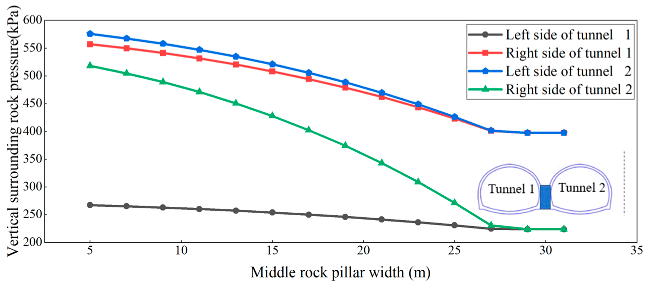
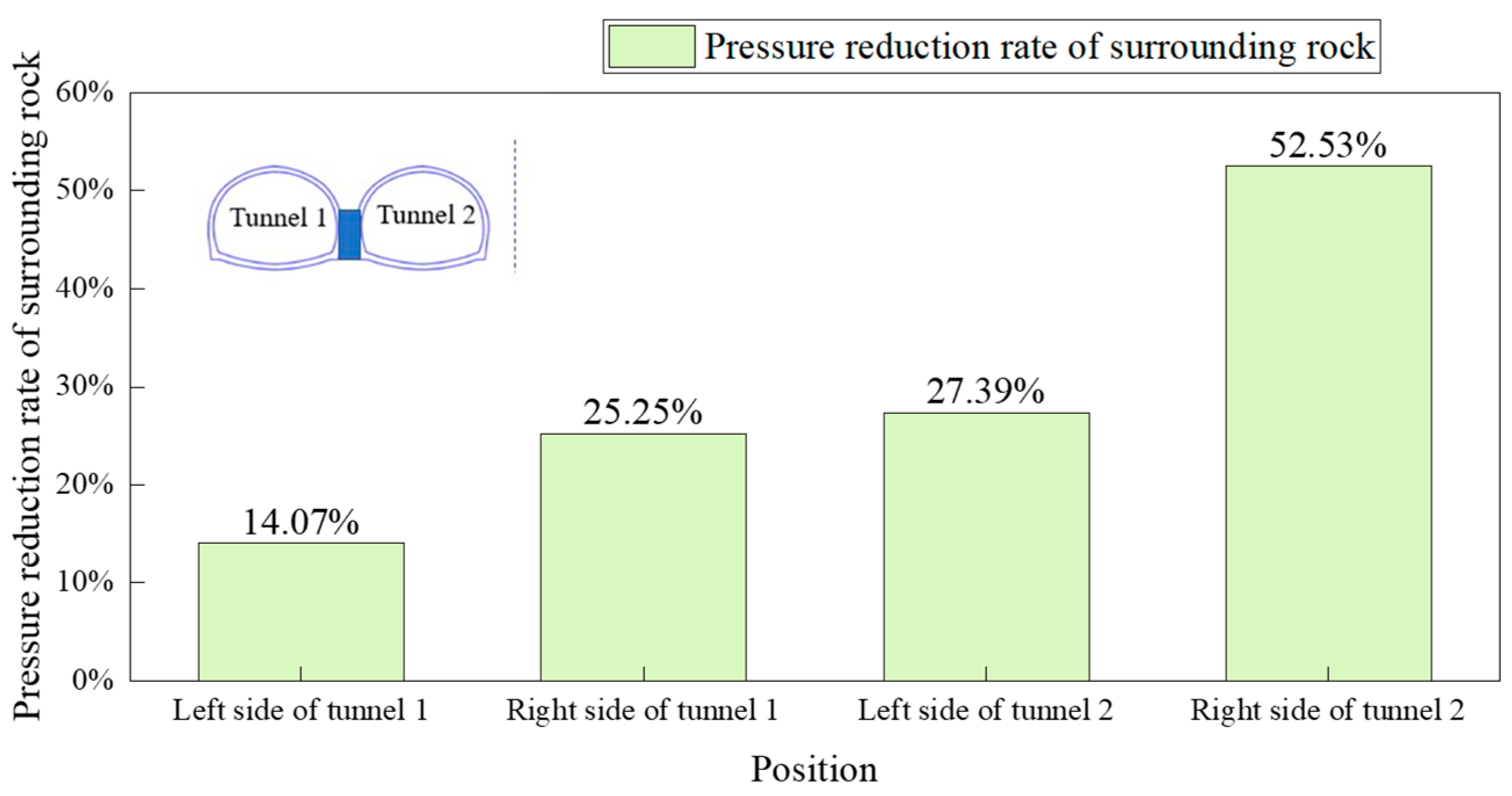
5.1. Influence of Parameters of Middle Rock Pillar on Surrounding Rock Pressure

(1) Influence of middle rock pillar width on surrounding rock pressure
The variation curve of the vertical surrounding rock pressure of the vault with the width of the middle rock pillar is shown in Figure 16.
As can be seen from Figure 16, the vertical surrounding rock pressure on the left side of tunnel 1 is the smallest. This is because the left side of tunnel 1 is farthest from the center of all composite arches. The vertical surrounding rock pressure on the right side of tunnel 1 and the left side of tunnel 2 is the highest and relatively close. This is because they are close in position and closest to the center of the double-hole composite arch. The right side of tunnel 2 is farthest from the center of the two-hole composite arch but closest to the center of the four-hole composite arch. Therefore, the vertical surrounding rock pressure on the right side of tunnel 2 is also large. It can be seen that the contribution of the double-hole additional surrounding rock pressure and four-hole additional surrounding rock pressure to the final surrounding rock pressure cannot be ignored.
When the clear distance is small, the vertical surrounding rock pressure calculated by this method is larger near the middle partition wall and the middle rock pillar. This is consistent with the mechanical characteristics of multi-arch tunnels and closely spaced tunnels. When the clear distance increases to 27 m, the vertical surrounding rock pressure on the left side of tunnel 1 is equal to that on the right side of tunnel 2. At the same time, the vertical surrounding rock pressure on the right side of tunnel 1 is equal to that on the left side of tunnel 2. This shows that the left and right double-arch tunnels have their independent pressure patterns.
(2) Influence of rock pillar strength on surrounding rock pressure
The variation curve of the vertical surrounding rock pressure of the arch roof with the strength of the middle rock pillar is shown in Figure 17.
It can be seen from Figure 17 that the strength of the middle rock pillar significantly improves the vertical surrounding rock pressure of the vault. When the strength of the middle rock pillar is lower than 2600 kPa, the vertical surrounding rock pressure of the arch roof is negatively correlated with the strength of the middle rock pillar.
When the strength of the rock pillar increases from 200 kPa to 2000 kPa, the reduction rate of surrounding rock pressure at each position is shown in Figure 18.
The increase in the strength of the middle rock pillar has the most obvious reduction rate for the vertical surrounding rock pressure on the right side of tunnel 2. The least obvious reduction rate for the vertical surrounding rock pressure on the left side of tunnel 1. The reduction rates of the left side of tunnel 2 and the right side of tunnel 1 are similar. This shows that the surrounding rock pressure closer to the middle rock pillar is more affected by it. After the strength of the middle rock pillar increases to 2600 kPa, the vertical surrounding rock pressure does not change with the strength of the middle rock pillar. At this time, the closely spaced multi-arch tunnel has become a commonly separated multi-arch tunnel. Therefore, when the clear distance is small, the strength of the middle rock pillar can be increased to reduce the surrounding rock pressure of the tunnel.

5.2. The Influence of Excavation Sequence on Surrounding Rock Pressure

The influence of the process load on surrounding rock pressure under different working sequences is realized by the load coefficient η . For the value of η , see Section 2.2. In Section 3.1, four reasonable excavation sequences of a four-hole double-line parallel closely spaced multi-arch tunnel have been given. The basic surrounding rock pressure of sequence 1 to sequence 4 after considering the load factor is shown in Table 10.
The final surrounding rock pressure calculated from Sequence 1 to Sequence 4 of the four tunnel arches is shown in Figure 19.
As can be seen from Figure 19, different construction sequences have a significant influence on the surrounding rock pressure of the four tunnel arches. Among them, the surrounding rock pressure calculated in sequence 2 is small and the curve is the most gentle. It indicates that the bias effect of sequence 2 on the tunnel is the least obvious. The calculated pressure of the surrounding rock in sequence 3 and sequence 4 is large and the curve fluctuation is large. It indicates that the bias effect produced by sequence 3 and sequence 4 is the most obvious. The surrounding rock pressure is calculated by sequence 1 and the fluctuation degree of the curve itself is between sequence 2 and sequence 3(or 4). It indicates that the bias effect generated by sequence 1 is also located between them.
In sequence 2, the left and right double-arch tunnels are the outer tunnels excavated first, and tunnel 2 and tunnel 3 are less disturbed by the rear tunnel. Therefore, the surrounding rock pressure is the lowest and the curve is the most gentle. In sequences 3 and 4, tunnel 2 is excavated first. Tunnel 2 itself is in the position of a large surrounding rock pressure and is subjected to the double disturbance of tunnel 1 and tunnel 3. Therefore, the surrounding rock pressure is large, which can cause a serious tunnel bias. For sequence 1, both tunnel 2 and tunnel 3 are disturbed by the post-construction tunnel, but not by the double disturbance. Therefore, the surrounding rock pressure calculated in sequence 1 is between the other three sequences.
To sum up, sequence 2 is the best.

5.3. Influence of Excavation Span on Surrounding Rock Pressure

The relation curve between the surrounding rock pressure and tunnel excavation span is shown in Figure 20.
When the excavation span is 6 m–8 m, the surrounding rock pressure on the left side of tunnel 1 and the right side of tunnel 2 is equal. The surrounding rock pressure on the right side of tunnel 1 and the left side of tunnel 2 is equal. This shows that the left and right lines are commonly separated multi-arch tunnels. At this time, increasing the span only changes the size of the two-hole composite arch, but does not form a four-hole composite arch.
When the excavation span increases from 8 m to 20 m, the vertical surrounding rock pressure at each position is no longer equal and increases linearly. This shows that the left and right lines are closely spaced multi-arch tunnels. At this time, the size of the double-hole composite arch and the size of the four-hole composite arch will increase with the increase in the tunnel span. From the slope of each curve, the vertical surrounding rock pressure on the left side of tunnel 1 is least affected by the excavation span. This is because the left side of tunnel 1 is farthest from the center of the two-hole composite arch and the center of the four-hole composite arch. The vertical surrounding rock pressure at the right side of tunnel 1, the left side of tunnel 2, and the right side of tunnel 2 increases obviously with the increase in the excavation span. This is because these three locations are close to the center of the composite arch.

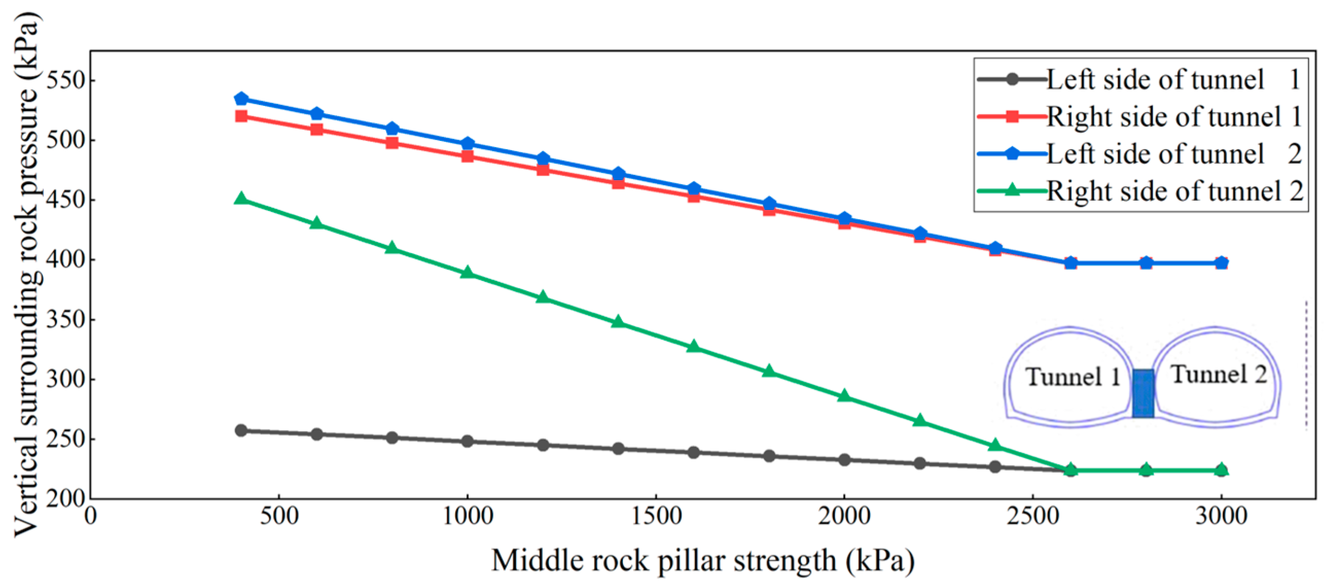
5.4. Influence of Strength of Rock and Soil Mass at the Top of Middle Partition Wall on Surrounding Rock Pressure

Figure 21 shows the change characteristics of the vertical surrounding rock pressure on both sides of the tunnel under different strengths of the rock mass in the middle partition wall.
It can be seen from Figure 21 that the rock mass at the top of the middle partition wall has a certain improvement on the vertical surrounding rock pressure. When the rock mass at the top of the middle partition wall increases from 100 kPa to 1200 kPa, the pressure reduction of the vertical surrounding rock varies from place to place. The vertical surrounding rock pressure on the left side of tunnel 1 decreases by 6.11%. The vertical surrounding rock pressure on the right side of tunnel 2 is reduced by 3.94%. The vertical surrounding rock pressure on the right side of tunnel 1 decreased by 11.11%. The vertical surrounding rock pressure on the left side of tunnel 2 is reduced by 10.92%.
When the rock mass at the top of the middle partition wall reaches 4200 kPa, the surrounding rock pressure no longer changes. At this time, the double-hole compound load is no longer generated, and the left and right tunnels are independent.
Therefore, the strength of the rock mass at the top of the middle partition wall significantly improves the vertical surrounding rock pressure near the middle partition wall.

6. Conclusions

Based on Protodyakonov’s arch theory, this paper establishes an extended load model for deep-buried four-hole closely spaced multi-arch tunnels and derives a formula for the surrounding rock pressure. The method’s effectiveness is verified by the comparison with standard algorithms and other literature. Through the discussion of the influencing factors, the following conclusions are drawn:
(1) When the width or strength of the middle rock pillar is small, the vertical surrounding rock pressure follows a closely spaced multi-arch tunnel mode, with higher pressures near the middle partition wall and rock pillar. When the width or strength of the middle rock pillar is large, the pressure follows a separate multi-arch tunnel mode, with a higher pressure near the middle partition wall;
(2) The excavation sequence significantly affects the surrounding rock pressure bias. Excavating the inner tunnel first leads to a greater disturbance from both the outer and inner tunnels. It is recommended to excavate the outer tunnel first, following the sequence “1→2→4→3”;
(3) The excavation span significantly influences the surrounding rock pressure. A smaller span shows a separate multi-arch mode, while a larger span gradually shifts the mode to a closely spaced multi-arch tunnel, with a more pronounced effect on the vertical pressure near the middle partition wall and rock pillar;
(4) The strength of the rock mass at the top of the middle partition wall has a limited improvement on the surrounding rock pressure, with a more noticeable reduction in pressure near the middle partition wall as the strength increases.
This calculation method has some limitations. It ignores the slight influence between tunnel 1 and tunnel 3, and tunnel 2 and tunnel 4. The influence of small guide holes is also ignored. At the same time, in order to reduce the influence of the biased pressure state, there are certain requirements for the construction sequence of the tunnel. These can lead to errors between the actual situation and the calculated result. Therefore, this method is mainly applicable to the relatively regular four-hole closely arranged multi-arch tunnel.

Author Contributions

Data curation, X.S. and S.W.; formal analysis, D.L. and X.S.; methodology, D.L. and J.W.; supervision, J.W. and Q.S.; validation, Q.S. and S.W.; and writing—original draft, X.S. All authors have read and agreed to the published version of the manuscript.

Funding

This research received no external funding.

Data Availability Statement

The original contributions presented in this study are included in the article. Further inquiries can be directed to the corresponding author(s).

Conflicts of Interest

The authors Q.S. is employed by the company Road & Bridge South China Engineering Co., Ltd. The remaining authors declare that the research was conducted in the absence of any commercial or financial relationships that could be construed as potential conflicts of interest.

Appendix A

Table A1. The relevant indices in the process of formula derivation.
IndicesImplicationUnit
q The vertical surrounding rock pressure k P a
q i The basic surrounding rock pressure k P a
q 1 i The   basic   surrounding   rock   pressure   of   tunnel   i   ( i = 1 , 2 , 3 , 4 ) k P a
q 2 The double hole additional surrounding rock pressure k P a
q 2 l The additional surrounding rock pressure in the left line double-hole multi-arch tunnel k P a
q 2 r The additional surrounding rock pressure in right line double-hole multi-arch tunnel k P a
q 2 x The   additional   surrounding   rock   pressure   of   the   double   hole   of   the   tunnel   side   wall   x
( x = 1 , 2 , 3 , 4 , 5 , 6 , 7 , 8 )
k P a
q 3 The maximum pressure of the loose earth above the middle partition wall k P a
q z The compressive strength of the middle partition wall k P a
q 4 the four holes’ additional surrounding rock pressure k P a
q 4 x The   additional   surrounding   rock   pressure   for   four   holes   of   tunnel   side   wall   x
( x = 1 , 2 , 3 , 4 , 5 , 6 , 7 , 8 )
k P a
q v i r The compressive strength of the unexcavated rock mass in the middle k P a
q S x The   final   vertical   surrounding   rock   pressure   x   ( x = 1 , 2 , 3 , 4 , 5 , 6 , 7 , 8 ) k P a
e T x The   horizontal   surrounding   rock   pressure   x   at   the   top   ( x = 1 , 2 , 3 , 4 , 5 , 6 , 7 , 8 ) k P a
e S T x The   horizontal   surrounding   rock   pressure   x   at   the   bottom
( x = 1 , 2 , 3 , 4 , 5 , 6 , 7 , 8 )
k P a
e B x The   final   horizontal   surrounding   rock   pressure   x   at   the   top
( x = 1 , 2 , 3 , 4 , 5 , 6 , 7 , 8 )
k P a
e S B x The   final   horizontal   surrounding   rock   pressure   x   at   the   bottom
( x = 1 , 2 , 3 , 4 , 5 , 6 , 7 , 8 )
k P a
R c The saturated uniaxial compressive strength of rock M P a
R s The design compressive strength of the rock mass at the top of the middle partition wall k P a
R p The compressive strength of the middle rock pillar k P a
P v i r The supporting force of the unexcavated rock mass k N / m
P z The supporting force of the middle partition wall k N / m
G m The left line shadow rock weight force k N / m
G m l The shadow rock weight force k N / m
H t The excavation height of the tunnel m
H 0 The vertical height from the tunnel floor to the beginning of the fracture surface m
H 3 The calculated height of the pressure of the loose surrounding rock at the top of the middle
partition wall
m
H z The height of the middle partition wall m
H q The vertical height of the balanced arch m
H q i The   load   height   of   the   sin gle   bearing   arch   of   tunnel   i   ( i = 1 , 2 , 3 , 4 ) m
H m l The load height of the composite bearing arch of the left line m
H m r The load height of the composite bearing arch of the right line m
H m The height of the four-hole composite arch m
H m The height of the four-hole composite arch under extremely good condition m
B t The excavation span of the tunnel m
B z The width of the middle partition wall m
B s The width of the middle pillar m
B q The horizontal width of the balanced arch m m
B q i The   sin gle   bearing   arch   width   of   tunnel   i   ( i = 1 , 2 , 3 , 4 ) m
B m l The tunnel left line double hole composite bearing arch width m
B m r The tunnel right line double hole composite bearing arch width m
B m The composite bearing arch width of the tunnel with four holes m
B p w The horizontal projection width of the outer fracture surface m
B p n The horizontal projection width of the inner fracture surface m
L Z The effective support width of the rock pillar m
r The weight of the surrounding rock k N / m 3
φ The fracture plane angle °
φ c The calculated friction angle°
θ The angle between the fracture plane and the horizontal direction°
λ The side pressure coefficient
f The firmness coefficient of the surrounding rock
η The process load influence coefficient
η i j The   influence   coefficient   of   process   load   of   tunnel   j   on   tunnel   i
( i , j = 1 , 2 , 3 , 4 )
β y The   influence   factor   y   ( y = 1 , 2 , 3 , 4 , 5 )
ξ The additional load correction factor
K The safety factor

References

  1. Wu, B.; Lu, M.; Huang, W.; Lan, Y.; Wu, Y.; Huang, Z. A Case Study on the Construction Optimization Decision Scheme of Urban Subway Tunnel Based on the TOPSIS Method. KSCE J. Civ. Eng. 2020, 24, 3488–3500. [Google Scholar] [CrossRef]
  2. Wu, L.; Zhang, X.; Zhang, Z.; Sun, W. 3D Discrete Element Method Modelling of Tunnel Construction Impact on an Adjacent Tunnel. KSCE J. Civ. Eng. 2020, 24, 657–669. [Google Scholar] [CrossRef]
  3. Tian, Z.; Sun, Y.; Zhao, Q.; Zhang, B.; Liu, W.; Zhang, X. Calculation method and evaluation of surrounding rock pressure of vertical shaft. Sci. Rep. 2024, 14, 7721. [Google Scholar] [CrossRef] [PubMed]
  4. Gao, H.; He, P.; Chen, Z.; Li, X. Study on a Surrounding Rock Pressure Calculation Method for Super-Large Section Highway Tunnels. Symmetry 2019, 11, 1133. [Google Scholar] [CrossRef]
  5. Hu, Z.; Zhang, J.; Yang, Y.; Wang, Z.; Xie, Y.; Qiu, J.; He, S.; Wang, X. Study on the Surrounding Rock Pressure Characteristics of Loess Tunnel Based on Statistical Analysis in China. Appl. Sci. 2022, 12, 6329. [Google Scholar] [CrossRef]
  6. Hu, J.; Xiao, J.; Yang, Z.; Xie, P.; Wen, H. Improved Protodyakonov’s Method of the Tunnel Surrounding Rock Pressure under the Seepage Condition of Weak Interlayer. Geofluids 2022, 2022, 1–14. [Google Scholar] [CrossRef]
  7. Yang, X.-L.; Jin, Q.-Y.; Ma, J.-Q. Pressure from surrounding rock of three shallow tunnels with large section and small spacing. J. Cent. South. Univ. 2012, 19, 2380–2385. [Google Scholar] [CrossRef]
  8. Hu, B.; Xiao, M.; Fu, X.; Yang, J.; Xu, C.; Wu, J.; Zhou, Y. FDEM numerical study of the influence law of geostress on state and pressure of tunnel surrounding rock. Front. Ecol. Evol. 2023, 11, 1237250. [Google Scholar] [CrossRef]
  9. Tong, J. General Formulas for Calculating Surrounding Rock Pressure of Tunnels and Underground Spaces. KSCE J. Civ. Eng. 2020, 24, 1348–1356. [Google Scholar] [CrossRef]
  10. Liu, J.; Xie, C.; Rao, J. Calculation Model and Influencing Factors of Surrounding Rock Loosening Pressure for Tunnel in Fold Zone. Adv. Civ. Eng. 2021, 2021, 1–15. [Google Scholar] [CrossRef]
  11. Yang, S.; Dai, R.; Ai, Z.; Li, X.; Zhang, C.; Huang, X. Analytical Solutions for the Mechanical Responses of Shallow Double-Arched Tunnel Subjected to Symmetric Loads. Adv. Civ. Eng. 2021, 2021, 1–33. [Google Scholar] [CrossRef]
  12. Li, R.; Zhang, D.; Fang, Q.; Liu, D.; Luo, J.; Fang, H. Mechanical responses of closely spaced large span triple tunnels. Tunn. Undergr. Space Technol. 2020, 105, 103574. [Google Scholar] [CrossRef]
  13. Cheng, X.; Liu, Y.; Liu, G.; Bu, Y. Study on Disturbance Characteristics of Surrounding Rock During Construction of Shallow Buried Bias Loess Tunnel with Small Clear Distance. Indian Geotech. J. 2024, 54, 2421–2442. [Google Scholar] [CrossRef]
  14. Tang, H.; Jiang, C.Y.; Deng, Q.; Bi, T.J.; Qin, Y.Q. A Method for Determining Surrounding Rock Load Borne by Antecedence Tunnel Lining of Shallowly Buried Double-arch Tunnel without Middle Drift. Rock Soil Mech. 2024, 45, 1170–1180. [Google Scholar] [CrossRef]
  15. Tang, H.; Jiang, C.; Deng, Q.; Bi, T.; Cha, Z. Calculation of Pressure on the Shallow-buried Double-arch Tunnel Without Middle Drift. KSCE J. Civ. Eng. 2022, 26, 4805–4814. [Google Scholar] [CrossRef]
  16. Gao, H.-J.; He, P.; Chen, Z. Calculation of Process Load of Deep-buried Asymmetric Multi-arch Tunnels. Chin. J. Geotech. Eng. 2020, 42, 1059–1066. [Google Scholar] [CrossRef]
  17. Li, P.; Wang, F.; Fan, L.; Wang, H.; Ma, G. Analytical scrutiny of loosening pressure on deep twin-tunnels in rock formations. Tunn. Undergr. Space Technol. 2019, 83, 373–380. [Google Scholar] [CrossRef]
  18. Wu, F.; He, C.; Kou, H.; Wang, B.; Meng, W.; Meng, H.; Guo, D. Discussion on Reasonable Clear Spacing of Twin-Tunnels in Weak Surrounding Rock: Analytical Solution and Numerical Analysis. KSCE J. Civ. Eng. 2022, 26, 2428–2442. [Google Scholar] [CrossRef]
  19. Hou, Y.; Zhang, D.; Li, R.; Chen, X.; Qi, W. Calculation Method for Surrounding Rock Pressure of Deeply Buried Triple-Arch Tunnel. Chin. J. Theor. Appl. Mech. 2024, 56, 3213–3226. [Google Scholar]
  20. JTG 3370.1-2018; Design Code for Highway Tunnels Volume 1 Civil Engineering. Ministry of Transport of the People’s Republic of China: Beijing, China, 2019.
  21. Bai, S.; Zhang, Y.; Fu, J.; Yang, X.; Yang, J. Study on Calculation Method for Surrounding Rock Pressure of Four-arch Tunnel. J. Highw. Transp. Res. Dev. 2023, 40, 163–171, 196. [Google Scholar] [CrossRef]
  22. Wu, X.; Tu, Z. Research of the Shape of Pressure Arch in Layered Rock Mass Based on the Protodyakonov’s Theory. In Proceedings of the 2017 7th International Conference on Manufacturing Science and Engineering (ICMSE 2017), Zhuhai, China, 11–12 March 2017. [Google Scholar]
  23. Gao, H.J.; He, P.; Chen, Z.; Li, X.Y. A Novel Calculation Method of Process Load for Extra-Large Section Tunnels. Symmetry 2019, 11, 1228. [Google Scholar] [CrossRef]
  24. Xie, C.; Tao, T.; Rao, J. Research Article Time-Varying Response Analysis of Surrounding Rock Construction Mechanics of a Double-Arch Tunnel without a Middle Pilot Tunnel and Suggestions for Tunnel Construction. Lithosphere 2022, 2022, 16. [Google Scholar] [CrossRef]
  25. Wang, C.; Liu, X.; Song, D.; Wang, E.; He, Z.; Tan, R. Structural response of former tunnel in the construction of closely-spaced cross-river twin tunnels. Tunn. Undergr. Space Technol. 2024, 147, 105652. [Google Scholar] [CrossRef]
  26. Qi, W. Study on Surrounding Rock Pressure Calculation and Pressure Arch Effect in Triple-arch Tunnel. Master’s Thesis, Beijing Jiaotong University, Beijing, China, 2022. [Google Scholar]
  27. Jiang, C.; Tang, H.; Deng, Q.; He, Z.; Bi, T. Calculation Method of Surrounding Rock Pressure of Deeply Buried Double-arch Tunnel without Middle Drift. J. Cent. South Univ. (Sci. Technol.) 2023, 54, 1168–1177. [Google Scholar] [CrossRef]
  28. Qu, H. Study on Load Mode of Road Tunnel with Extra-large Cross-section and Low Flat-ratio and Its Application. Ph.D. Dissertation, Tongji University, Shanghai, China, 2007. [Google Scholar]
  29. Li, H.; Guo, X. Research on Calculation Metheods of Earth Pressure on Muti-arch Tunnel for Highway. Rock Soil Mech. 2009, 30, 3429–3434. [Google Scholar]
  30. Chen, S.L.; Lee, S.C.; Gui, M.W. Effects of rock pillar width on the excavation behavior of parallel tunnels. Tunn. Undergr. Space Technol. 2009, 24, 148–154. [Google Scholar] [CrossRef]
  31. Liu, J.; Guo, X. A Study on Calculation Method of Surrounding Rock Pressure About Deep-Buried Tunnel with Small Spacing. Highway 2009, 200–205. [Google Scholar]
Figure 1. Derivation flow chart.
Mathematics 13 00286 g001
Figure 2. Schematic diagram of theoretical calculation of Pratt arch.
Mathematics 13 00286 g002
Figure 3. The influence of load on the post-construction tunnel to the pre-construction tunnel.
Mathematics 13 00286 g003
Figure 4. Calculation model of surrounding rock pressure in multi-arch tunnel.
Mathematics 13 00286 g004
Figure 5. Calculation model of surrounding rock pressure in closely spaced tunnel.
Mathematics 13 00286 g005
Figure 8. Tunnel naming.
Mathematics 13 00286 g008
Figure 9. Load distribution of four-hole double-line parallel closely spaced multi-arch tunnel.
Mathematics 13 00286 g009
Figure 10. The load distribution model of the double-arch tunnel.
Mathematics 13 00286 g010
Figure 11. L z > 0 .
Mathematics 13 00286 g011
Figure 12. L z < 0 .
Mathematics 13 00286 g012
Figure 13. The cross section of the single-line multi-arch tunnel.
Mathematics 13 00286 g013
Figure 14. Comparison of vertical surrounding rock pressure for arch roof 1 [29].
Mathematics 13 00286 g014
Figure 15. Comparison of vertical surrounding rock pressure for arch roof 2.
Mathematics 13 00286 g015
Figure 16. Influence of middle rock pillar width on vertical surrounding rock pressure on both sides.
Mathematics 13 00286 g016
Figure 17. Influence of middle rock pillar strength on vertical surrounding rock pressure on both sides of the tunnel.
Mathematics 13 00286 g017
Figure 18. The pressure reduction rate of the surrounding rock.
Mathematics 13 00286 g018
Figure 19. Influence of excavation sequence on vertical surrounding rock pressure of tunnel vault.
Mathematics 13 00286 g019
Figure 20. Influence of excavation span on surrounding rock pressure on both sides of the tunnel.
Mathematics 13 00286 g020
Figure 21. Influence of the strength of the rock mass at the top of the middle partition wall on the pressure of vertical surrounding rock on both sides of the tunnel.
Mathematics 13 00286 g021
Table 1. β 1 value reference.
Tunnel Span 0–0.2B 0.2B–0.4B 0.4B–0.6B 0.6B–0.8B 0.8B–1.0B
β 1 1.8 1.75 1.70–1.751.65–1.70 1.50–1.65
Table 2. β 2 value reference.
Depth–Span Ratio <0.6 0.6–1.0 1.0–1.2 1.2–1.6 >1.6
β21.5–1.21.2–1.01.00.90.8
Table 3. β 3 value reference.
Inclusion Factor0 1 2 3
β31.01.051.11.15
Table 4. β 4   value reference.
Supporting EffectUnsupportedWeak SupportOrdinary SupportStrong Support
β41.01.0–1.351.351.35–1.5
Table 5. β 5   value reference.
Rock Grade>IIIIVVVI
β51.21.11.00.9
Table 6. Construction sequence.
Sequence 1Sequence 2Sequence 3Sequence 4
1→2→3→41→2→4→32→1→3→42→1→4→3
Table 7. Calculation sheet of η 12 .
Tunnel SpanDepth–Span RatioInclusion FactorSupporting EffectRock Grade
Judging standard20.80Strong supportV
β i 1.81.111.51
η 12 1.32
Table 8. Calculation sheet of η 23 .
Tunnel SpanDepth–Span RatioInclusion FactorSupporting EffectRock Grade
Judging standard180.80Strong supportV
β i 1.181.111.51
η 23 0.87 < 1
Table 9. Surrounding rock pressure calculation.
x q 1 x ( k P a ) q 2 x ( k P a ) q 3 ( k P a ) q 4 x ( k P a ) q s x ( k P a ) e s T x ( k P a ) e s B x ( k P a )
1228.1041.393824.41293.9068.7383.02
2228.10151.7389.46507.2968.7393.56
3172.80151.733899.87462.4072.1985.86
4172.8041.39164.93379.1372.1997.65
5228.1041.3938164.93434.4281.68107.13
6228.10151.7399.87517.7081.6895.34
7172.80151.733889.46451.9959.2484.07
8172.8041.3924.41238.6059.2473.54
Table 10. Basic surrounding rock pressure under different excavation sequences.
Sequence q 11 q 12 q 13 q 14
Sequence 1 (1→2→3→4) η 12 · γ H q 1 η 23 · γ H q 2 η 34 · γ H q 3 γ H q 4
Sequence 2 (1→2→4→3) η 12 · γ H q 1 η 23 · γ H q 2 H q 3 η 43 · γ H q 4
Sequence 3 (2→1→3→4) γ H q 1 η 21 η 23 · γ H q 2 η 34 · γ H q 3 γ H q 4
Sequence 4 (2→1→4→3) γ H q 1 η 21 η 23 · γ H q 2 γ H q 3 η 43 · γ H q 4
Disclaimer/Publisher’s Note: The statements, opinions and data contained in all publications are solely those of the individual author(s) and contributor(s) and not of MDPI and/or the editor(s). MDPI and/or the editor(s) disclaim responsibility for any injury to people or property resulting from any ideas, methods, instructions or products referred to in the content.

