Abstract
The aim of this study is to develop sensorless high-speed tracking control for surface-mounted permanent magnet synchronous motors by taking the rotor position offset error and time-varying load torque into consideration. This proposal combines an extended state observer with an adaptation position algorithm, employing only the measurement of electrical variables for feedback. First, a rotatory coordinate model of the motor is proposed, wherein the rotor position offset error is considered as a perturbation function within the model. Second, based on the aforementioned model, a rotary coordinate model of the motor is extended in one state to estimate the load torque, as well as the rotor’s position and speed, despite the presence of the rotor position offset error. Through Lyapunov stability analysis, sufficient conditions were established to guarantee that the error estimations were bounded. Finally, to validate the feasibility of the proposed sensorless scheme, experiments were conducted on the Technosoft® development platform, where the alignment routine was disabled and an intentional misalignment between the magnetic north pole and the stator’s south pole was established.
Keywords:
extended state observer; rotor position offset error; sensorless control; surface-mounted permanent magnet synchronous motor MSC:
93D30
1. Introduction
Electrical motors operate as the main actuators in both domestic and industrial applications. They can be classified according to specific features, such as the type of power source, construction, or electrical operation. In this context, permanent magnet synchronous motors (PMSMs) provide a rapid dynamic response, higher efficiency, and a higher torque-to-inertia ratio for applications requiring high precision and efficiency. The aforementioned characteristics of PMSMs provide advantages over DC and induction motors in variable speed applications, including robotics, machinery, and propulsion systems in electric, aquatic, and aerial vehicles [1,2,3]. In general, for the effective and precise control of a PMSM, the angular position or rotor speed is measured using mechanical or optical sensors. Nonetheless, these sensors increase the size and cost of the PMSM. Moreover, the sensors are susceptible to malfunctions, diminishing the motor’s reliability [4,5].
In the last few decades, sensorless control techniques for permanent magnet synchronous motors (PMSMs) have been developed to address the aforementioned issues. These techniques depend only on electrical variables for feedback, specifically the stator currents and voltages. Sensorless methods are categorized into two main categories: model-based and high-frequency injection methods. The first method involves the injection of a high-frequency signal for rotor position detection, commonly used in low-speed and zero-speed applications [6]. The second method involves estimating the rotor position using the back electromotive force (back-EMF), commonly used in high-speed applications [7]. The efficiency of this method is directly related to the assessment of the electrical positioning quality, as this signal contains important information regarding the rotor’s position. Inaccurate estimations may result from multiple issues, which researchers can tackle either alone or collectively. Some of the factors are discussed below.
The sensorless control method that employs back-EMF estimation requires current sensors, and in certain instances voltage sensors, to collect back-EMF information. The collected data are subsequently transmitted through a digital controller utilizing a low-pass filter (LPF) and an analog-to-digital converter (ADC). Consequently, the whole drive system depends on the accurate measurement of electrical signals. In this scenario, variations in the temperature of the analog electronic device or inaccuracies in ADC quantization can cause a nonlinear response in the current sensor, leading to a back-EMF measurement error. The main component of any nonlinear errors is the direct current (DC) offset error. It leads to a pulse in the d-axis voltage within the synchronous coordinate system. As a result, an error in rotor position tracking occurs, decreasing the sensorless control and operational performance of the PMSM drive [8,9].
The alignment routine is a common stage in starting up PMSM drive systems. The procedure involves setting the zero rotor position by matching the rotor’s magnetic north pole with the stator’s south pole. A successful alignment routine ensures the system’s efficiency during the torque–speed control stage. However, an initial misalignment causes a rotor position offset error during steady-state operation, which makes control less effective. In some cases, significant misalignment can prevent the initialization of the control stage [10]. In sensor-based systems, a rotor position offset error is unavoidable in the application of PMSMs. In sensorless schemes, an inaccurate estimation of the rotor position results in an increased rotor position offset error. This consequently negatively affects the overall performance of the drive system [11,12]. Moreover, in scenarios involving load torque variations, specific application-related constraints may be worsened, including a decrease in the lifespan of the machine and electronic driver, a diminished operational range, and decreased overall system control performance [13].
In a sensorless scheme, the most common method to estimate the electrical position is the implementation of a phase-locked loop (PLL) that takes the back-EMF induced in the coil stator as an input signal. The PLL operates as a closed-loop system utilizing a proportional integrator (PI) as an estimator, primarily aimed at synchronizing the output signal with the input signal in terms of both the phase and frequency. Its popularity in sensorless schemes is because of its straightforward implementation and simple structure [14,15]. We share the latest studies on this topic below. In Ref. [16], a PLL with compensatory positioning utilizing an LPF was employed to replace a tangent function. In Ref. [17], a study was focused on the development of a tangent function PLL to address the speed reversal issue. Ref. [18] suggests that a PLL combined with a signal suppressor link can reduce rotor position errors in both high- and low-speed operations. High-speed PMSM schemes encounter difficulties when there is a variation in speed. An improved AQPLL in [19] increased the accuracy of mechanical estimate states. A novel quasi-super-twisting observer, integrated with an enhanced quadrature phase-locked loop, was proposed in the work of [20] to alleviate issues with low-order harmonic components and position error estimation. It is noticeable that numerous techniques employing adaptive super-twisting observers have been developed in the previous decade to improve the rotor position and motor speed performance [21]. However, the implementation of these techniques requires tackling the issue of chattering, complicating the design challenge; at times, the efficacy of the sensorless controller may be adversely affected [22].
Notwithstanding these advancements, the recent literature has revealed that PLL methodologies still face several challenges, such as an insufficient dynamic response during transient operations, phase noise in electrical estimations, parameter sensitivity, initial synchronization difficulties, and instability issues [23,24]. In order to address the previously mentioned issues, the main objective of this research is to address position estimation under the study of misalignment issues and the speed tracking control problem for PMSMs in spite of time-varying load torque variations. The only measurements are of electrical variables.
This proposal combines an extended state observer (ESO) and adaptation position algorithm in a rotating coordinate system, unlike other studies that utilize a stationary coordinate system, which have demonstrated commendable performance outcomes [25]. The methodology of using an ESO has led to significant improvements in the sensorless scheme across several studies; moreover, its low complexity and simple implementation facilitates straightforward gain tuning [26,27,28]. Here, the proposed ESO estimates mechanical variables, while the extended state estimates the load torque variations, which are then utilized as feedback for the drive system. Hence, an adaptive position approach is developed based on Lyapunov stability analysis; it utilizes the fact that significant rotor position offset errors lead to a non-zero error in the d-axis current estimation during steady-state operation [29].
The proposed scheme’s structure removes the need to modify the rotating coordinate system for back-EMF voltage estimation and the design of a PLL for rotor position and speed computation, as well as the use of a trigonometric function, thereby simplifying the algorithm’s implementation complexity. Unlike other algorithms, such as the Kalman filter and intelligent control, the relatively low complexity of this approach may aid engineers in speeding up early-stage industrial projects.
The main contributions of this paper include the following: (i) a rotatory coordinate model with nonlinear terms in the function of the rotor position offset error is proposed to address the observer design; (ii) this model approach allows us to define a Lyapunov candidate function to derive an adaptive position algorithm to achieve the direct estimation of back-EMF signals, hence avoiding the need for a trigonometric function or the direct design of a PLL for collecting position and speed data; and (iii) a sensorless controller scheme is proposed to force the rotor speed to track a desired reference, maintaining the alignment of the electrical and mechanical angles of the rotor in spite of time-varying load torques.
The remainder of this article is structured as follows: Section 2 presents the fundamental background and mathematical preliminaries. Section 3 establishes the dynamical model of the PMSM. The problem statement addressed in this article is presented in Section 4. Section 5 addresses the observer designed for the estimation of mechanical variables, including stability analysis. Section 6 presents simulations and experimental results proving the effectiveness of the proposed approach. Finally, the conclusion and possibilities for future works are summarized in Section 7.
2. Mathematical Preliminaries
Throughout the whole of this paper, the set of real numbers is represented by . The notation represents the minimum (maximum) eigenvalue of a matrix, . The absolute value for any real number, x, is denoted by , and the Euclidean norm for a vector, , is denoted as . The symbol represents the transpose matrix of . Additionally, in Section 5, the following lemmas will be used.
Lemma 1
([30], Appendix B). Let be a continuously differentiable function with continuous partial derivatives up to at least the second order. Assume the following:
- .
- .
Furthermore, the following conditions apply:
- If the Hessian matrix satisfies , then is a positive definite function (at least locally).
- If the Hessian matrix for all , then is a globally positive definite function.
Lemma 2
([31]). Let and be matrices with compatible dimensions. Then, the following inequality holds:
where Λ is a symmetric positive definite matrix with a suitable dimension.
3. PMSM Mathematical Model
The dynamical model of the surface-mounted PMSM in a rotating coordinate system, derived with the usual assumptions of phase symmetry between phases, equal inductances, and low magnetic hysteresis, is given by [28]:
where and are the stator currents in the rotatory axis reference frame (measured outputs), and are the stator voltages in the rotatory axis reference frame (control inputs), is the rotor electric angle, and is the rotor speed. In addition, the parameter is the stator resistance, is the stator inductance, is the rotor torque constant, is the rotor flux linkage, is the rotor inertia, is the number of pole pairs, and is the viscous friction constant, and is the load torque. Here, the main causes of disturbances are abrupt load torque variations.
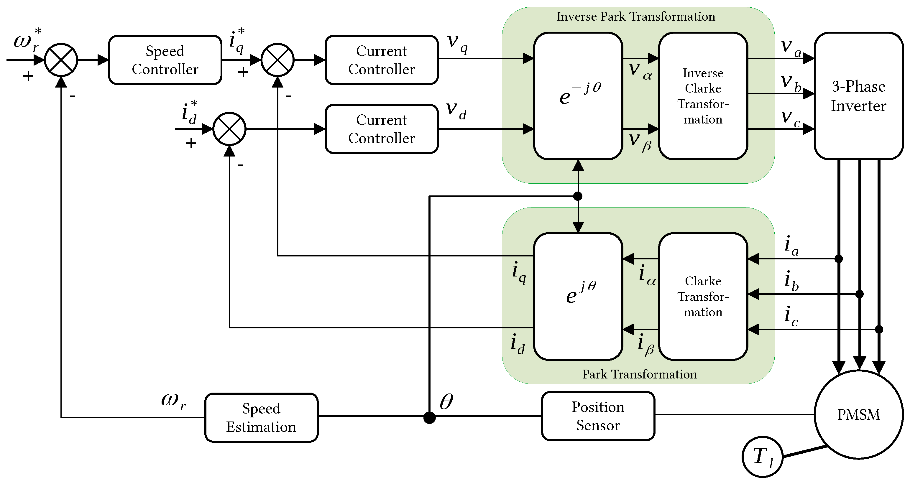
The field-oriented control (FOC) scheme is commonly applied to drive the PMSM (see Figure 1). The FOC requires a control action to set as zero the that allows for a decoupling of the system (2–5) and diminish the electromotive force. Then, the control of both the rotor speed and electromagnetic torque is feasible, forcing the current to track a stator current reference, , which is considered as a virtual control input [32].
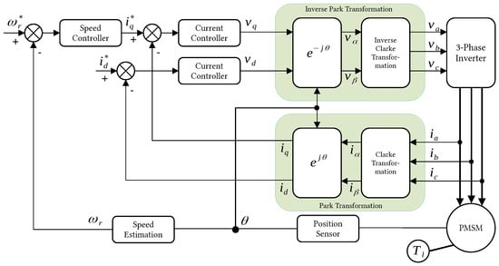
Figure 1.
Field-oriented control (FOC) scheme. Position and electrical current sensors are required for successful implementation.
4. Problem Statement
Commonly, the PMSM drive is based on the FOC scheme; see Figure 1. In this control method, via a Clarke transformation, the stator currents of a three-phase electric motor, , are projected onto two orthogonal stationary vectors, . The first vector defines the magnetic flux, and the second one defines the torque. Then, using the following rotation transformation,
the vectors are projected onto two orthogonal rotatory vectors, , through the Park transformation, defined as
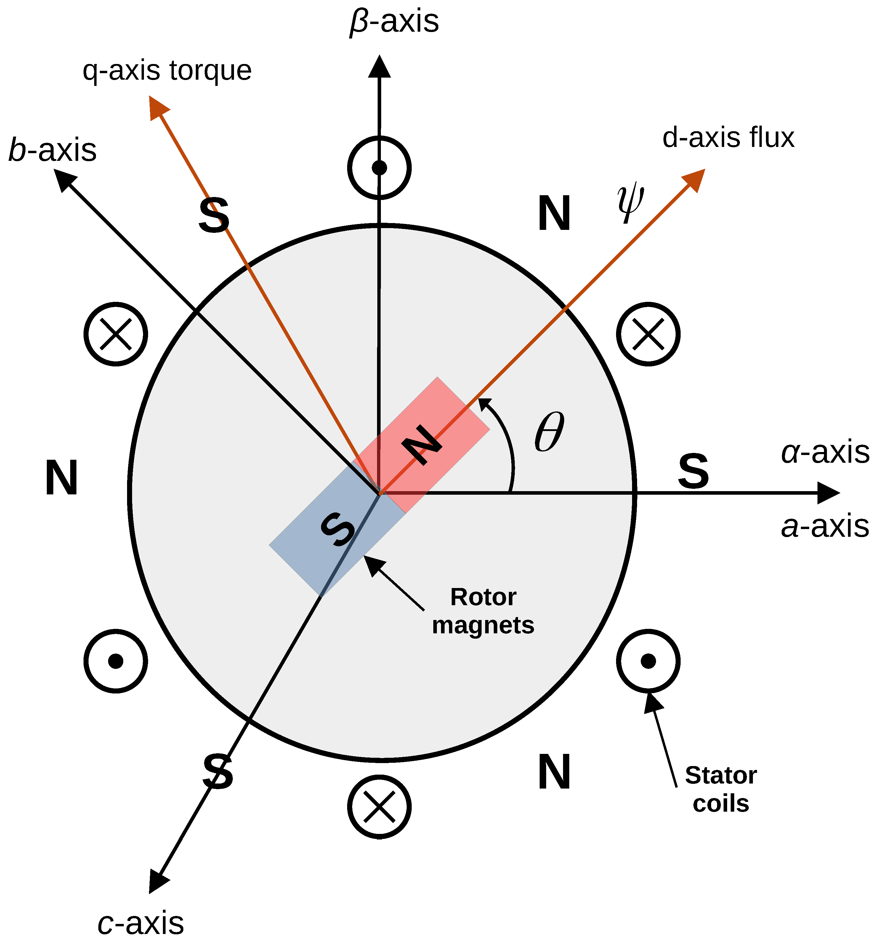
This approach allows for the stabilization of an AC electric motor comparable to that of a DC motor, allowing for the separate control of the magnetization and torque [33]. To accomplish this, it is essential to measure the rotor electrical angle . This angle is the position of the rotor relative to the terminal voltage and is described by the angle formed between the reference frames of the stationary vectors and the rotating vectors ; see Figure 2. An accurate measurement of the rotor electrical angle is essential for a robust and high-precision FOC scheme. Otherwise, the efficiency and performance of the control algorithm decrease, affecting the reliability of the entire system [34,35].
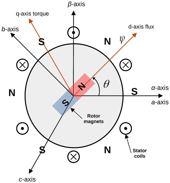
Figure 2.
The relative position of the reference frames (, ) and (d, q) is established using the rotor electrical angle.
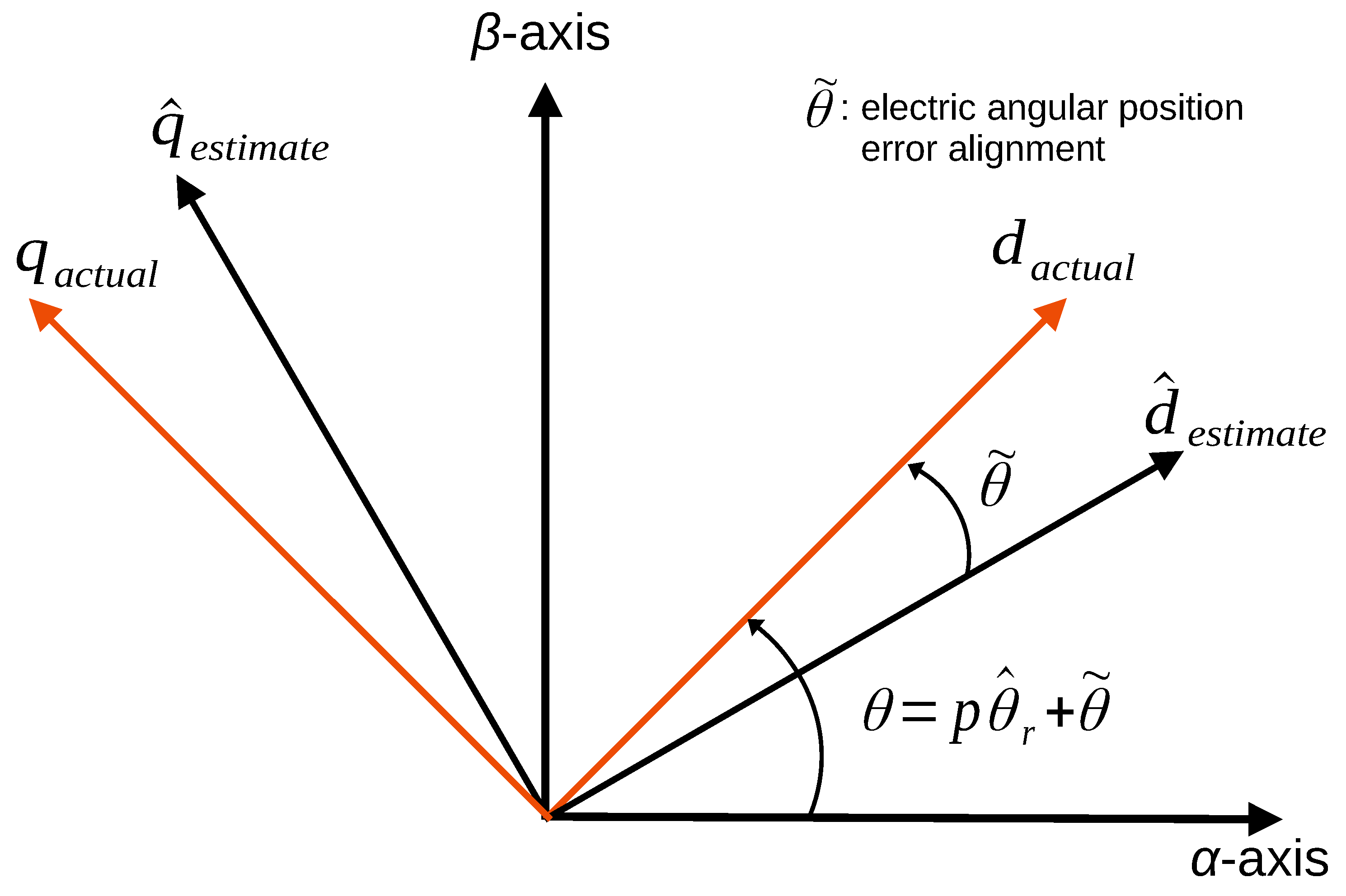
Actually, the drive system startup requires an alignment routine for the rotor electrical angle. However, in actual practice, a measurement error could exist, either due to a bad initialization routine or a malfunctioning sensor. If there is a misalignment of the electrical angle of the rotor, then there is an error, , between the actual electrical angle and its measurement; see Figure 3.
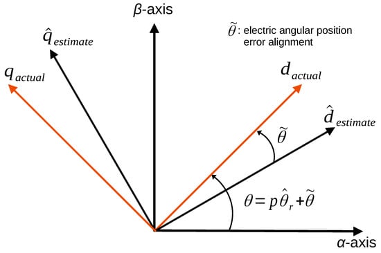
Figure 3.
Electrical angular position error between the actual PMSM synchronous frame and the estimated synchronous reference frame. The mathematical representation is defined in Equation (8).
In order to maintain the high performance and high precision of the drive system despite the misaligned rotor electrical angle, the error angle needs to be compensated for in the Park transformation, as follows:
with , where is the mechanical angular position of the rotor measured by a sensor. Now, the resulting two orthogonal rotatory vectors projected by the Park transformation defined in (8) yield to the following rotatory reference frame model:
with
where the functions and represent the back-emf generated by the angular position error, the function describes the electromagnetic torque produced by the magnetic flux created by and , and is the speed measurement inaccuracy. The solution to Equation (12) incorporates the initial condition , which can be interpreted as the initial misalignment between the actual and estimated synchronous reference frames. Notice that when , the result corresponds to the conventional synchronous reference frame model (2–5).
For technical reasons, we make the following assumptions throughout this whole paper:
- (A1)
- The domain of physical motion for the PMSM, denoted as , is defined by the following set:where the constants , , , and represent the maximum values for the stator currents, rotor speed, and load torque that the PMSM can withstand. The bounds specified in (16) can be computed analytically using the methodology described in Ref. [36]. Alternatively, in technical scenarios, these bounds can be obtained from the datasheet provided by the manufacturer of the PMSM.
Assumption A1 guarantees that the solution of (9) will remain uniformly bounded regardless of whether there are variations in the load torque.
The control objective of this work is to design sensorless speed tracking control for a surface-mounted PMSM, given by (9), forcing the speed to track a desired speed, , and stabilize the current to zero; that is,
in spite of unknown time-varying load torque variations and a misaligned rotor electrical angle. Since mechanical variables are not available for feedback, the only measurements available are of the signal currents and voltages of the stator.
5. Mechanical Variable Estimation Based on an ESO
This section presents the design of an ESO. Such an observer estimates the electrical angular position and speed of the rotor, taking into account the time-varying load torque as an extended state of (9).
First, in (8), consider as an extended state, i.e., , and define . Then, system (9) can be represented by an extended-state system as follows:
where is the control input vector, with
Note that is an unknown function but is bounded by the physical motion in (16). To overcome the mechanical variable estimation and load torque variation problem, an ESO is proposed in the following subsection.
5.1. Observer Design
First, this section describes the ESO as follows:
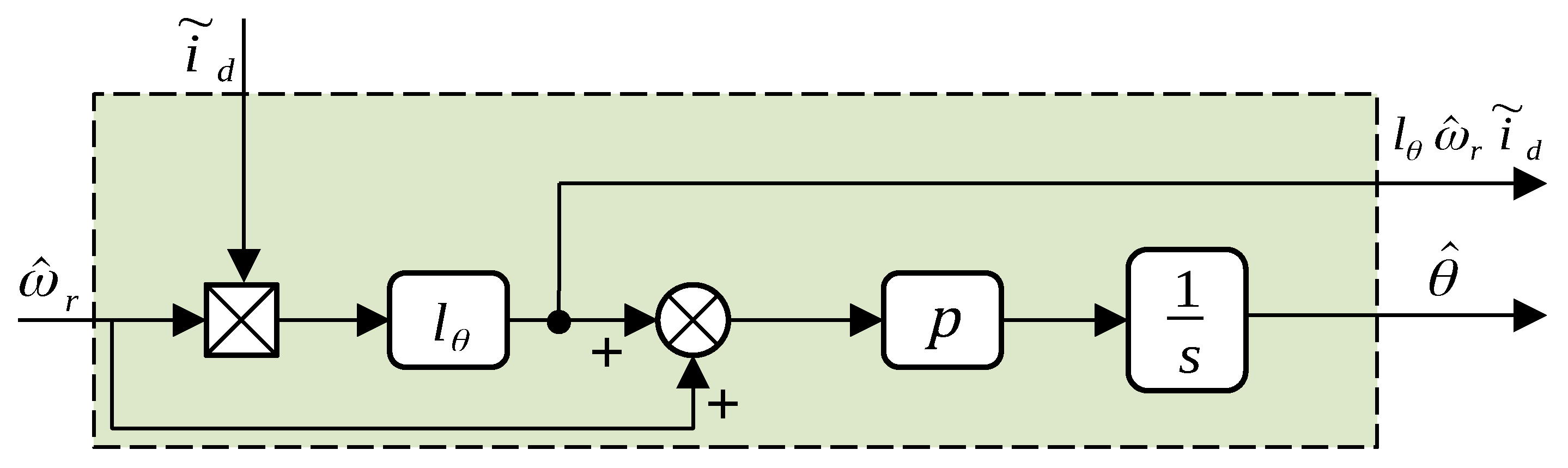
where defines the estimated state vector of , represents the estimation of , is the observer gain matrix, and the positive gain is used as an adaptation rule to estimate the electrical angle position (in Section 5.2, the complete deduction of (24) will be presented).
Now, let us denote the observation error as and . Then, considering (18–20) and (23–24), the observer error dynamics are described by the following equations:
Here, assuming that is observable, we can choose an observer gain matrix, , such that all eigenvalues of matrix have negative real parts. Meanwhile, the following is henceforth assumed:
- (A2)
- In (21), it is assumed that is uniformly bounded in and locally Lipschitz in , i.e.,where the positive constant represents the Lipschitz constant.
5.2. Stability Analysis
The analysis model enables a definition of a Lyapunov function in relation to the position dynamics. The impact of an alignment error on the stability of the solutions is examined. Firstly, consider the following Lyapunov candidate function:
Here, is a symmetric positive definite matrix, and . It is clear that . The gradient of is given by
which, evaluated at , is equal to zero, i.e., . Next, the Hessian matrix is given by
and is positive definite at . Therefore, based on Lemma 1, the function is positive definite, at least locally.
The time derivative of along the trajectories of (25) yields to
Based on Lemma 2, if and , we can assert the following inequality:
According to Ref. [37], it is feasible to express the Lipschitz condition (27) as follows:
where the nonlinear term is locally Lipschitz in domain and uniformly bounded in , while is a constant matrix. Notice that the inequality (33) is a less conservative version of the Lipschitz condition (27). If we choose the observer gain matrix as where is a positive scalar and consider (33), the function in (32) can be rewritten as follows:
Before computing the time derivative of the electrical position error, we must rewrite the function . More precisely, we will split the second term on the right side of Equation (34) as follows:
with and . Now, substituting (13) and (35) in , the inequality in (34) can be reformulated as
To compensate for the cross term , it is essential to incorporate the measurement of the rotor speed in the formulation of . However, the actual measurement of the rotor speed is unavailable. To address the absence of this measurement in (26), we propose utilizing the term as an adaptation rule to estimate the electrical angular position of the rotor, where . Consequently, the inequality (36) is simplified in the following approach:
Now, taking into account the boundaries and , we may combine the last two terms with the first term of Equation (37) using a matrix, , of a well-defined dimension. The resultant equation is bounded as follows:
Now, we define
and
where the matrix is a solution for the algebraic Riccati Equation (39) for any symmetric positive definite matrix, . In addition, in Equation (40), the perturbed vector is defined as follows:
The vector contains all the perturbed terms as the load torque and back-emf due to the angular position error alignment. Assume that vector follows the linear growth bound, meaning that there exist positive constants, and , such that the following inequality holds:
Afterwards, Equation (38) is redefined as
Now, given Assumption (A1), the subsequent inequality of is expressed as
with . Then,
Thus, we conclude that is negative semi-definite. Therefore, we may conclude that the solutions are bounded. In a real scenario, if the solutions do not satisfy the criteria (32) and considering that the vector is a function of the electrical alignment error, the motor could experience a loss of synchronization, a loss of torque, or poor control performance.
6. Simulations and Experimental Results
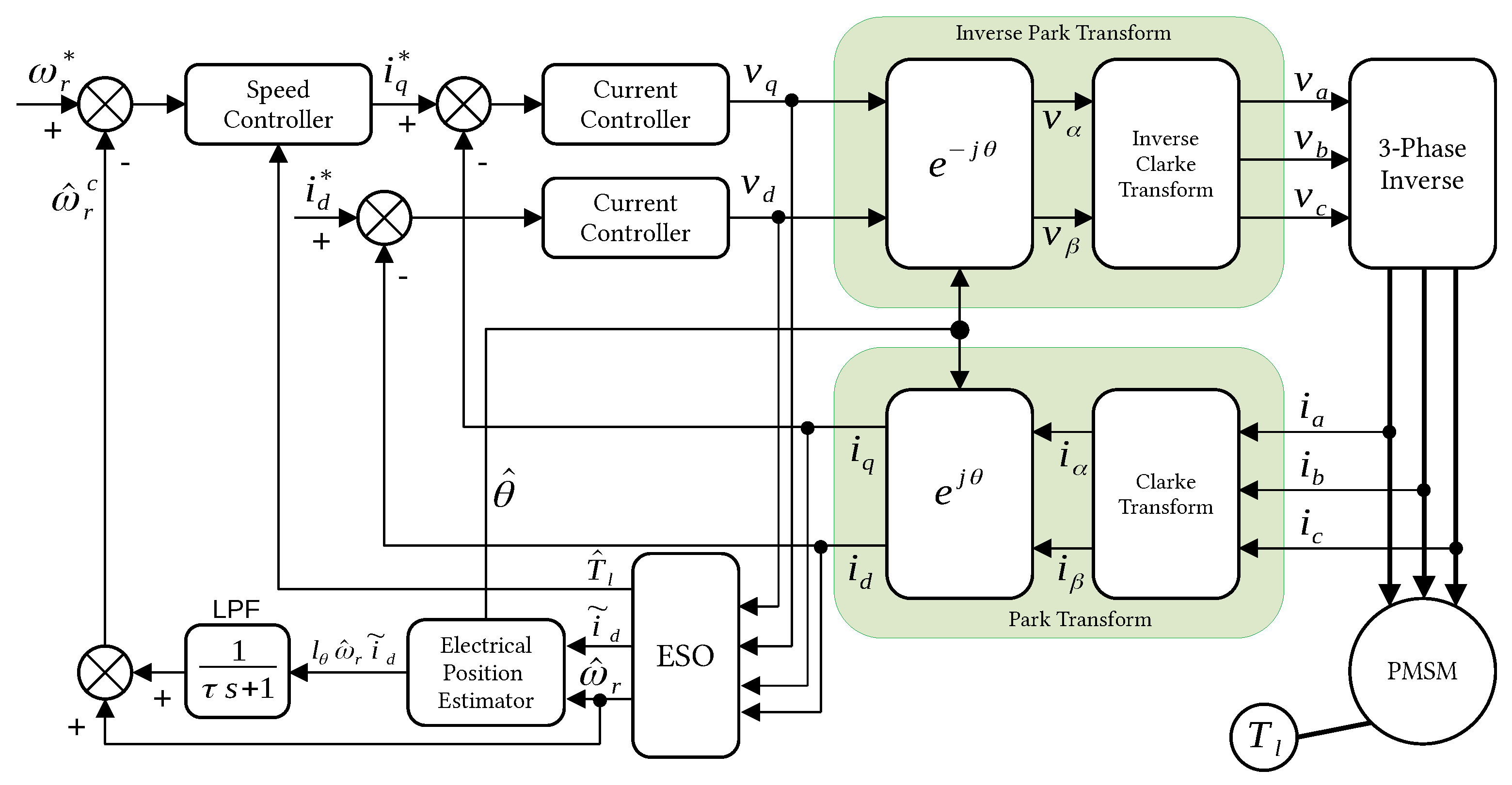
To demonstrate the theoretical results, we present simulations and experiments carried out on an industrial PMSM benchmark: the Technosoft MCK28335 Kit C-Pro Digital Control real-time platform. The equipment was manufactured by Technosoft® in Bevaix, Switzerland. The drive system utilized a nominal controller that operated in the FOC scheme, as illustrated in Figure 1. This research introduced a robust sensorless controller that modified the FOC scheme, as illustrated in Figure 4. For validation, measurements from the incremental encoder installed on the PMSM rotor were collected.
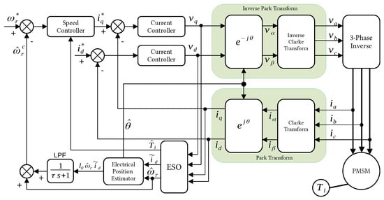
Figure 4.
Complete schematic of the sensorless controller based on an extended state observer and position estimator.
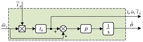
Here, it was necessary to calculate from the derivative of the estimated electrical position. In order to suppress the high-frequency components resulting from the computation of the derivative of the term , a first-order low-pass filter, LPF, was proposed:
Nonetheless, the LPF intrinsically generates a phase delay. The variable phase delay may lead to a decrease in the performance of the whole drive system. In order to reduce the phase delay and enhance the filtering efficacy, the cut-off frequency of the LPF must be appropriately adjusted according to the fundamental frequency of the rotor speed of the micro PMSM.
Figure 4 illustrates a PI controller combined with the ESO defined in Equations (23) and (46) within a closed-loop configuration that excludes feedback from actual position measurements. The current controller under consideration, with , is described in the following form:
and the speed controller is defined as
where , and represent proportional gains, while , and denote integral gains. Figure 4 illustrates the whole sensorless FOC controller scheme proposed in this paper. The load torque feedback estimated by the ESO will enhance the controller’s robustness, ensuring that the speed error remains bounded despite external disturbances. In the next subsection and for a comparative study, graphical results illustrate the position and speed measurements used to evaluate the performance of the proposed sensorless control scheme. Before presenting the simulation and experimental results, we outline the development platform.
6.1. Platform Description
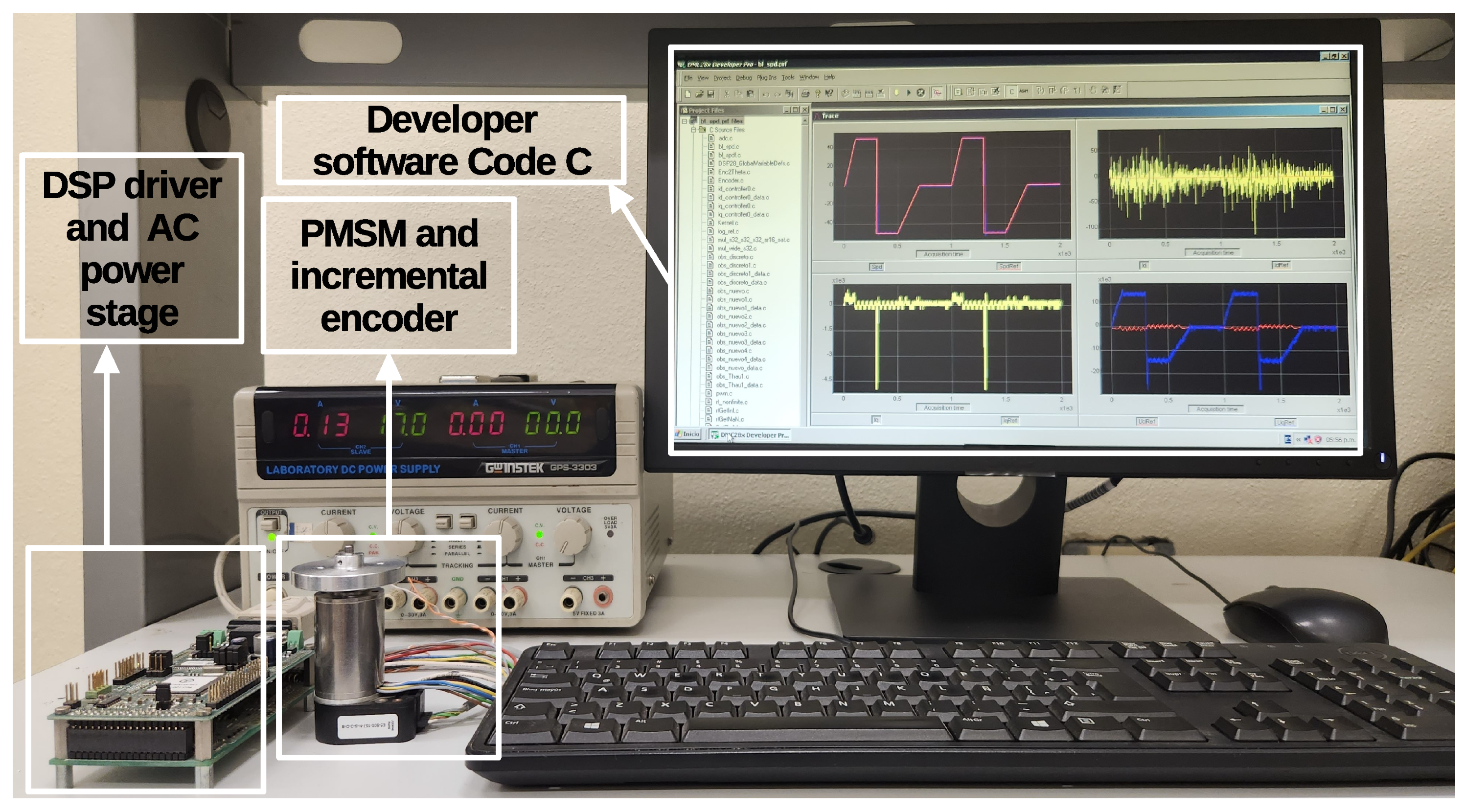
The MCK28335 Kit C-Pro Digital Control is a motion control kit using the TMS320F28335 digital signal processor manufactured by Technosoft® in Bevaix, Switzerland; Figure 6 illustrates the setup of the experimental platform. The development platform featured a PMSM with Hall sensors and a 500-line encoder, incorporated a PM50v3.1 power module (Technosoft®) with MOSFET transistors operating at a switching frequency of up to 50 kHz, and included A/D and D/A converters. Additionally, the system provided an integrated development environment (IDE) and required libraries to facilitate the programming and debugging of code C. The nominal parameters of the PMSM are presented in Table 1.
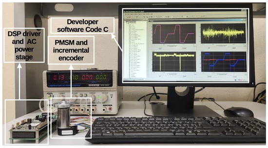
Figure 6.
Technosoft® experimental development platform PMSM setup.

Table 1.
Motor parameters and specifications of MBE.300E.500.
6.2. Simulation Results
In the simulations, the sampling time for the speed control loop was , while the sampling time for the current control loop and the estimation loop was . The initial conditions were set as
The controller proportional gains were established as , and , while the integral gains were set as , and . The observer gain matrix was set as
Based on the parameters outlined in Table 1 and the boundaries defined in domain , the Lipschitz constant was calculated to be , and the matrix . Additionally, the gain of the estimator position . Considering the previously mentioned parameters, , and the matrices and , the solution of the Riccati Equation (39) yielded
The test simulations were intended to track and estimate the desired variable speed, considering a known load torque and an initial misalignment of the stator and rotor magnetic fields, . Figure 5 illustrates the tracking behavior of the current and the speed in response to the application of a time-varying torque.
Figure 7 illustrates the tracking of the rotor speed trajectory of the PMSM through different speed changes and zero-speed crossings. It is essential for understanding that a value of zero can be determined by aligning the magnetic fields of the PMSM, as shown in Figure 2. The d-axis was deliberately oriented at degrees relative to the -axis of the stationary frame, resulting in an initial error in the current calculation via the Park transform; see Figure 2.
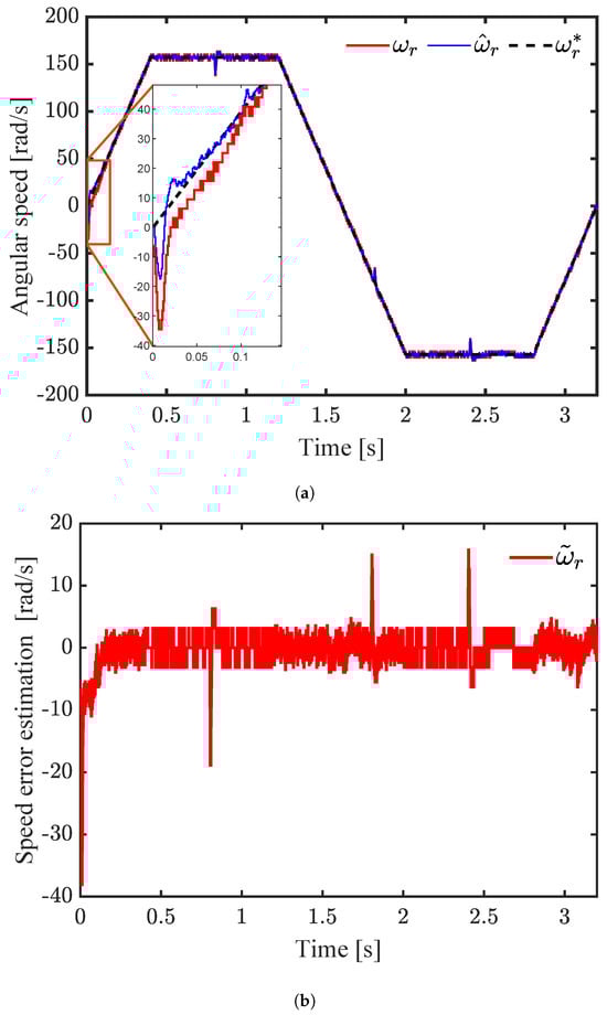
Figure 7.
Simulation results: PMSM controller system under load torque variations. (a) Speed tracking performance under FOC scheme, (b) speed error estimation.
The load torque applied during the performance test is shown in Figure 8a. The initial misalignment of the magnetic fields at the test’s beginning induced errors in the current decomposition performed by the Park transform, thereby impacting the performance of the state estimations. Figure 8b illustrates a significant, fast transient error in the load torque estimation. This explains why the speed control exhibited poor transient behavior, as seen in Figure 7a, a zoomed-in view of the trajectory. Despite the applied load torque and estimation errors, the rotor speed successfully recovered and remained stable around the reference value. Conversely, the rotor trajectory successfully crossed zero while retaining stability throughout the sign transition.
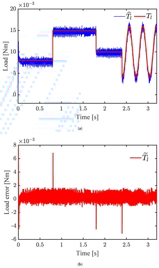
Figure 8.
Simulation results: PMSM controller system under load torque variations. (a) Applied load torque, (b) load torque error estimation performance.
The effects of initial misalignment on the performance of the estimated current component can be observed in Figure 9a. These occurred because , which is related to the magnetic flux, is influenced by the rotor’s electrical position. Consequently, an initial position error, , different from zero may result in a transient error, as shown in the zoomed-in view in Figure 9b. As the estimated electrical position coincided with the measured value, this error decreased progressively.

Figure 9.
Simulation results: PMSM controller system with proposed sensorless control scheme under load torque variations. (a) Stator current , (b) current error estimation performance.
Figure 10a depicts the behavior of the signal. The increases in the magnitude of the torque component current correlated with the load torque variations applied to the PMSM during the test, as is directly related to the electromagnetic torques of the machine. Figure 10b illustrates the estimated current error throughout the test, which converged to the measured value with a small error, , nearing zero in a steady state, even during transient operation.
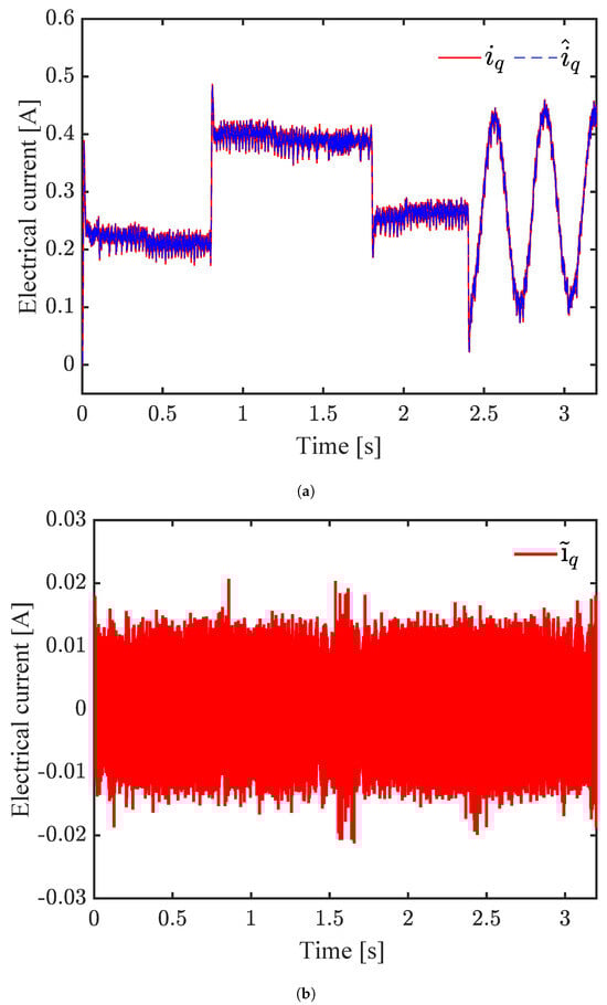
Figure 10.
Simulation results: PMSM controller system with proposed sensorless control scheme under load torque variations. (a) Stator current , (b) current error estimation performance.
Figure 11a illustrates the rotor position determined by the incremental encoder and the estimated position. Both signals exhibited an offset, which was expected since before starting the control routine, the encoder’s initial position was set to zero while the magnetic fields of the rotor and stator remained misaligned. Figure 11b illustrates the position error. A zoomed-in view of the graph reveals a signal with an average amplitude corresponding to the initial misalignment according to Equation (50). This finding suggests that the proposed observer compensates for the initial position error by precisely estimating the electrical position.

Figure 11.
Simulation results: PMSM controller system with proposed sensorless control scheme under load torque variations. (a) Measured and estimated rotor position, (b) position error estimation performance.
6.3. Implementation Results
In the test presented below, the sampling times used in the simulation were maintained, the parameters from Table 1 were considered, and the experimental development platform shown in Figure 6 was used. The initial conditions at for the observer states were set to zero. The system’s initial conditions for the speed and current were established as zero, and the initial load torque was unspecified; concurrently, the position value was set as
The zero rotor position was determined by aligning the magnetic fields of the PMSM; refer to Section 4. To prevent field alignment and establish the conditions of Equation (54), the initial alignment routine in the code was simply disabled. For this test, we selected the same gains as for the simulation results. During this test, the motor was subjected to an unknown time-varying friction load torque. As a result, certain variables were comparable throughout the experiments and simulations, except for the applied torque; therefore, we will highlight the main significant aspects of the experimental test.
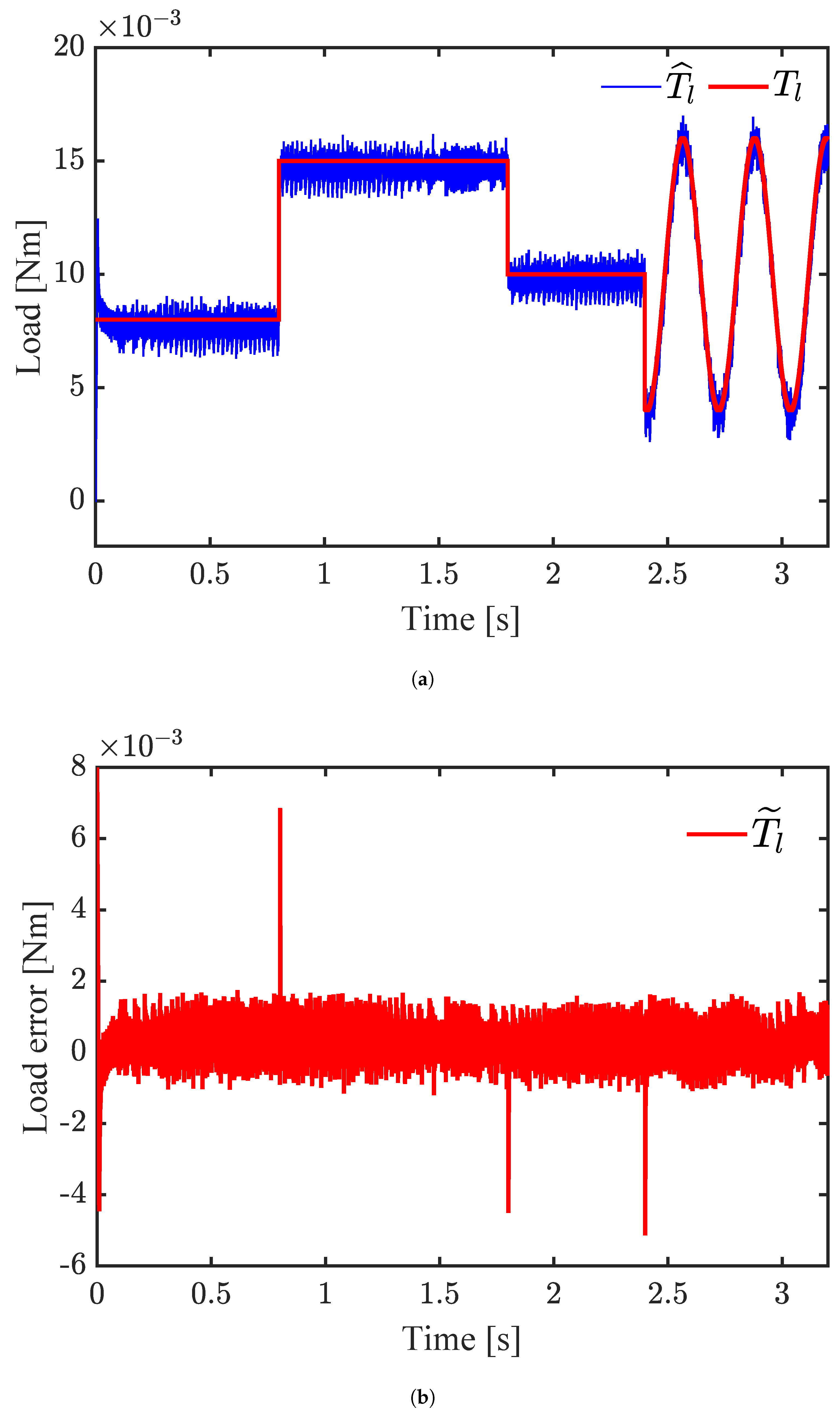
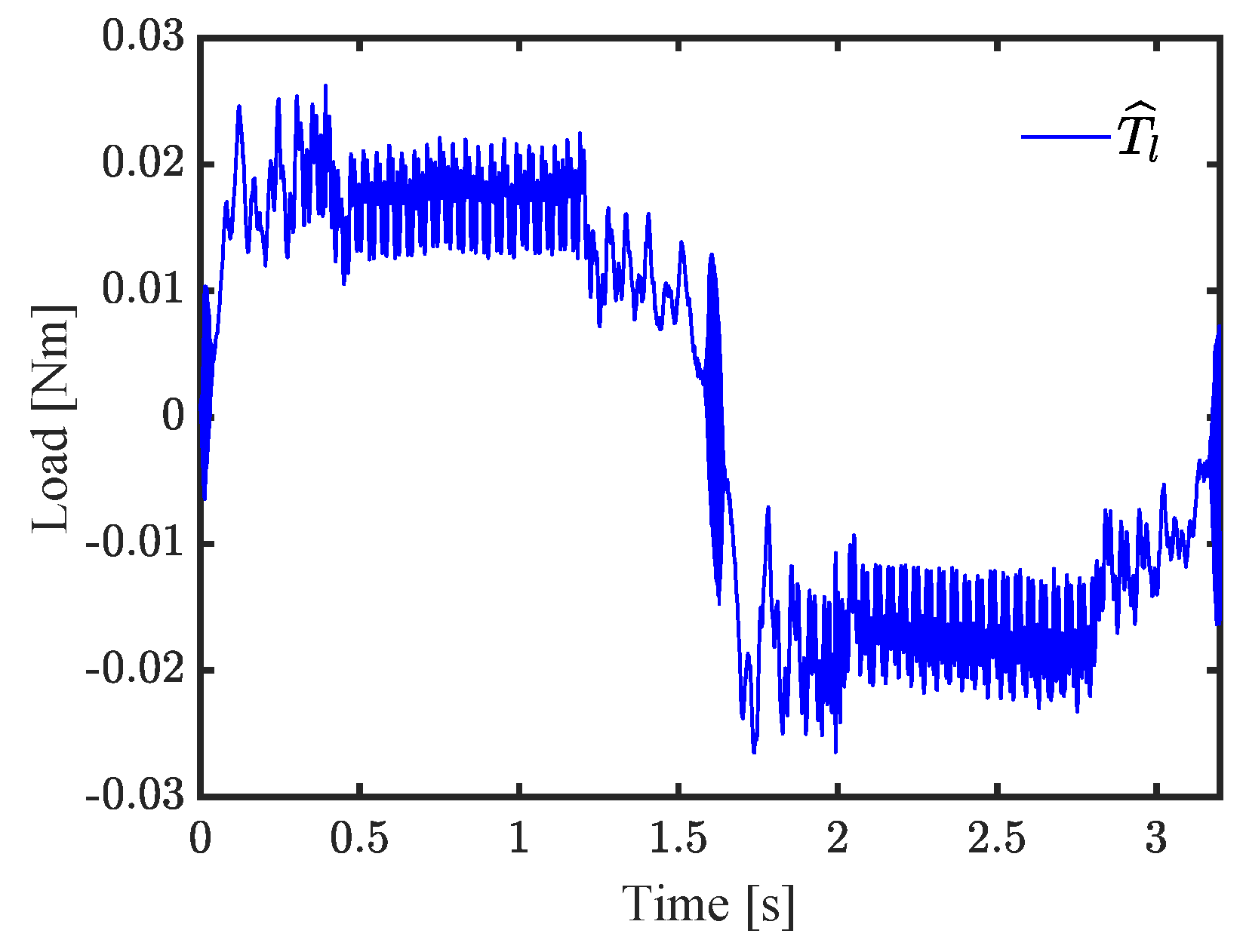
Figure 12 shows the estimated load torque during the performance test, reaching a maximum of 0.02 Nm when the rotor speed stabilized.
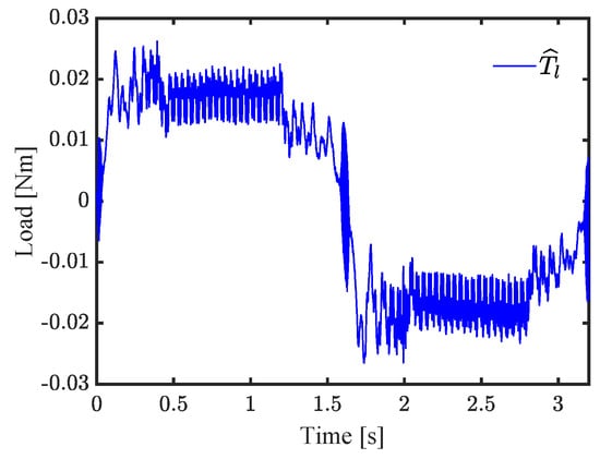
Figure 12.
Experimental results: PMSM controller system with proposed sensorless control scheme under load torque variations. Applied load torque.
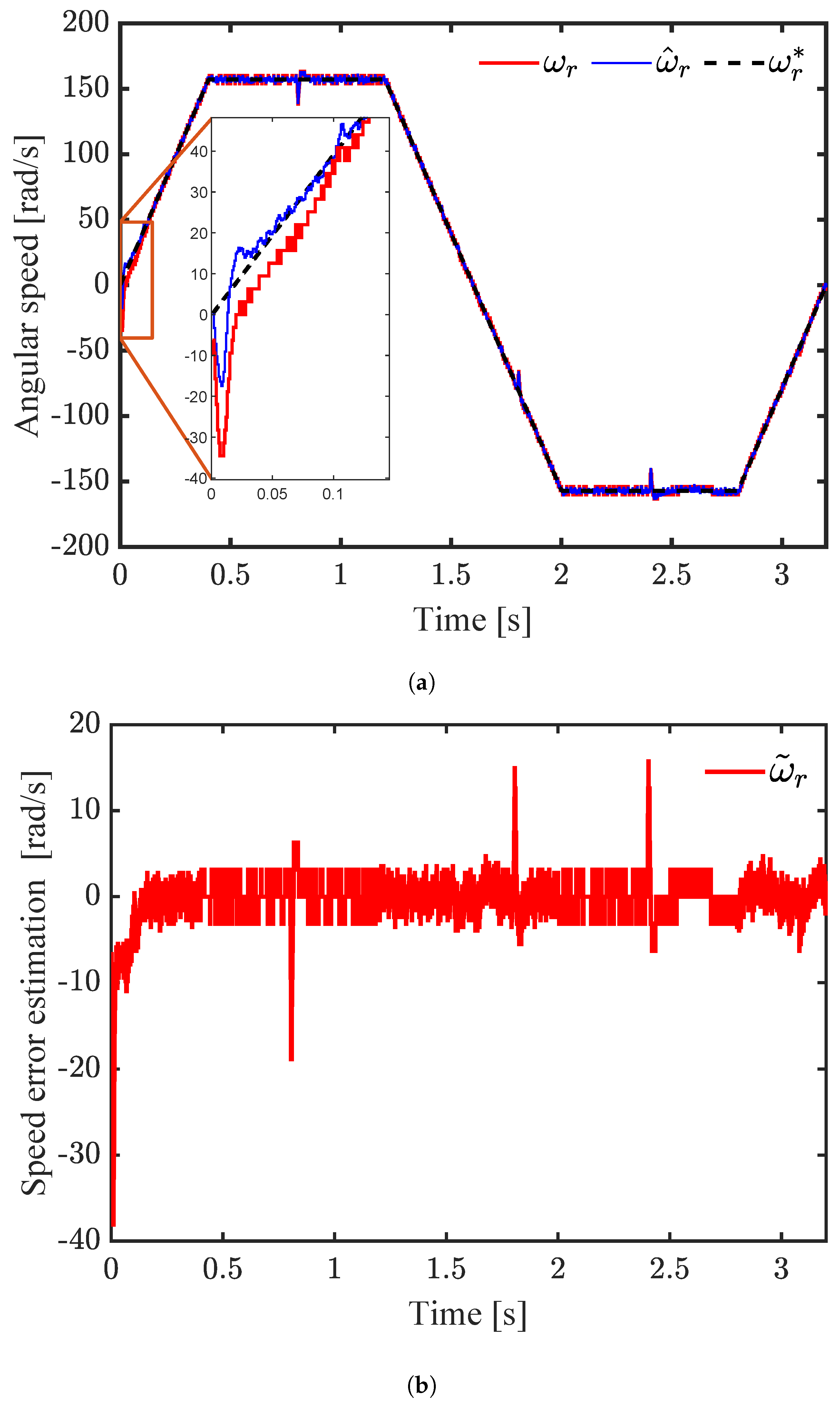
The initial increase in the trajectory in Figure 13a demonstrates the transitory characteristics of the signals. The initial misalignment and applied torque generated noise in the zero-speed estimate and caused a delay in the measured speed, thus prolonging the settling time for control. These effects can be observed in the behavior of speed error estimation; see Figure 13b. Despite error estimation and control, the trajectory recovered and successfully crossed zero, maintaining stability during the sign transition, exhibiting good tracking and robustness in relation to the reference signal.
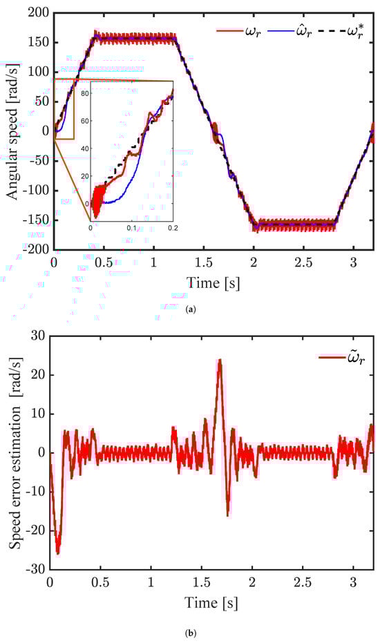
Figure 13.
Experimental results: PMSM controller system under load torque variations. (a) Speed tracking performance under FOC scheme, (b) speed error estimation.
The experimental signals may have exhibited distinct behaviors compared to those in the simulations since parametric uncertainties, the unmodeled dynamics of the power inverter circuit, and current sensor inaccuracies were not considered. However, it can be observed that the fundamental theoretical aspects analyzed in previous sections were still satisfied.
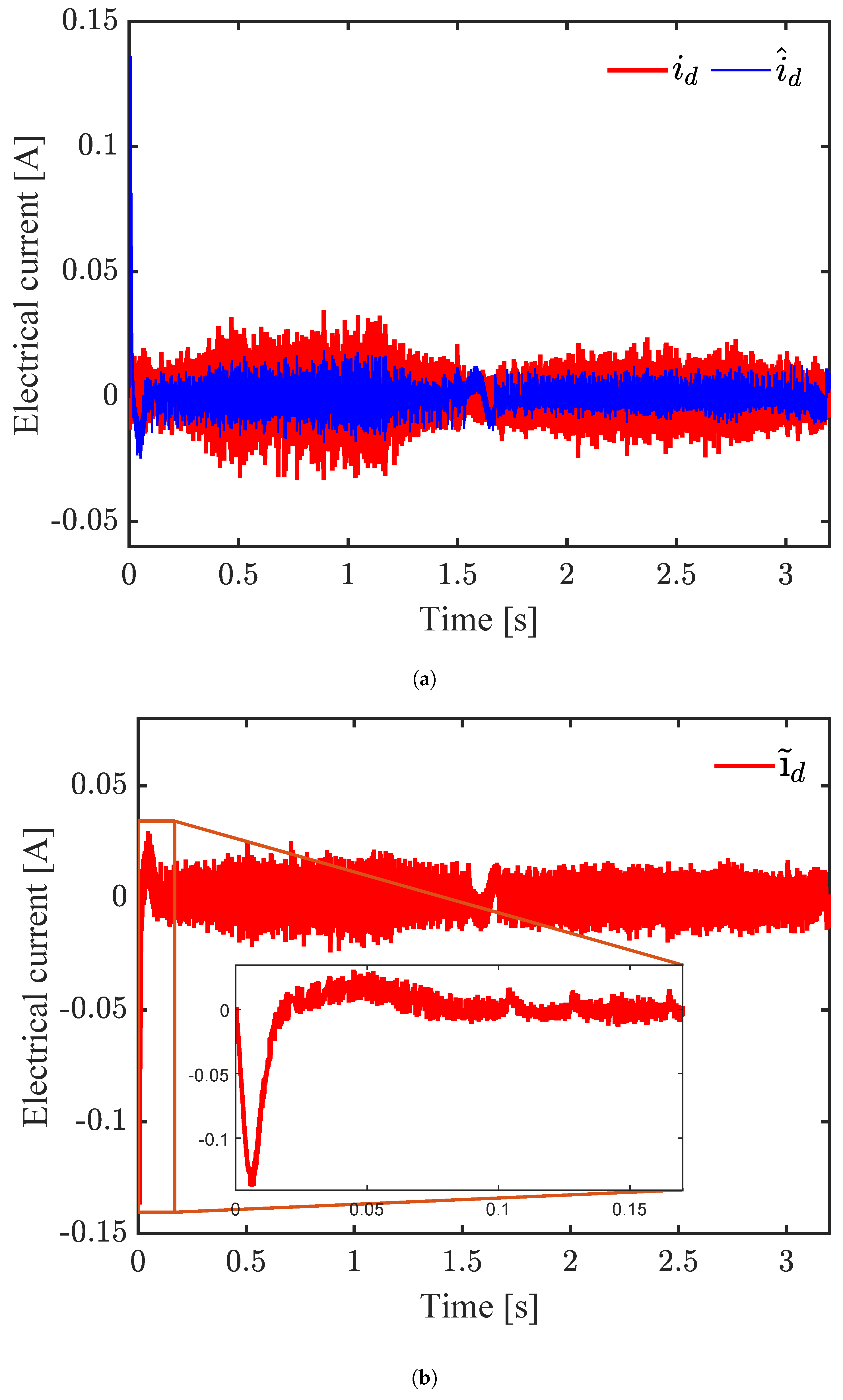
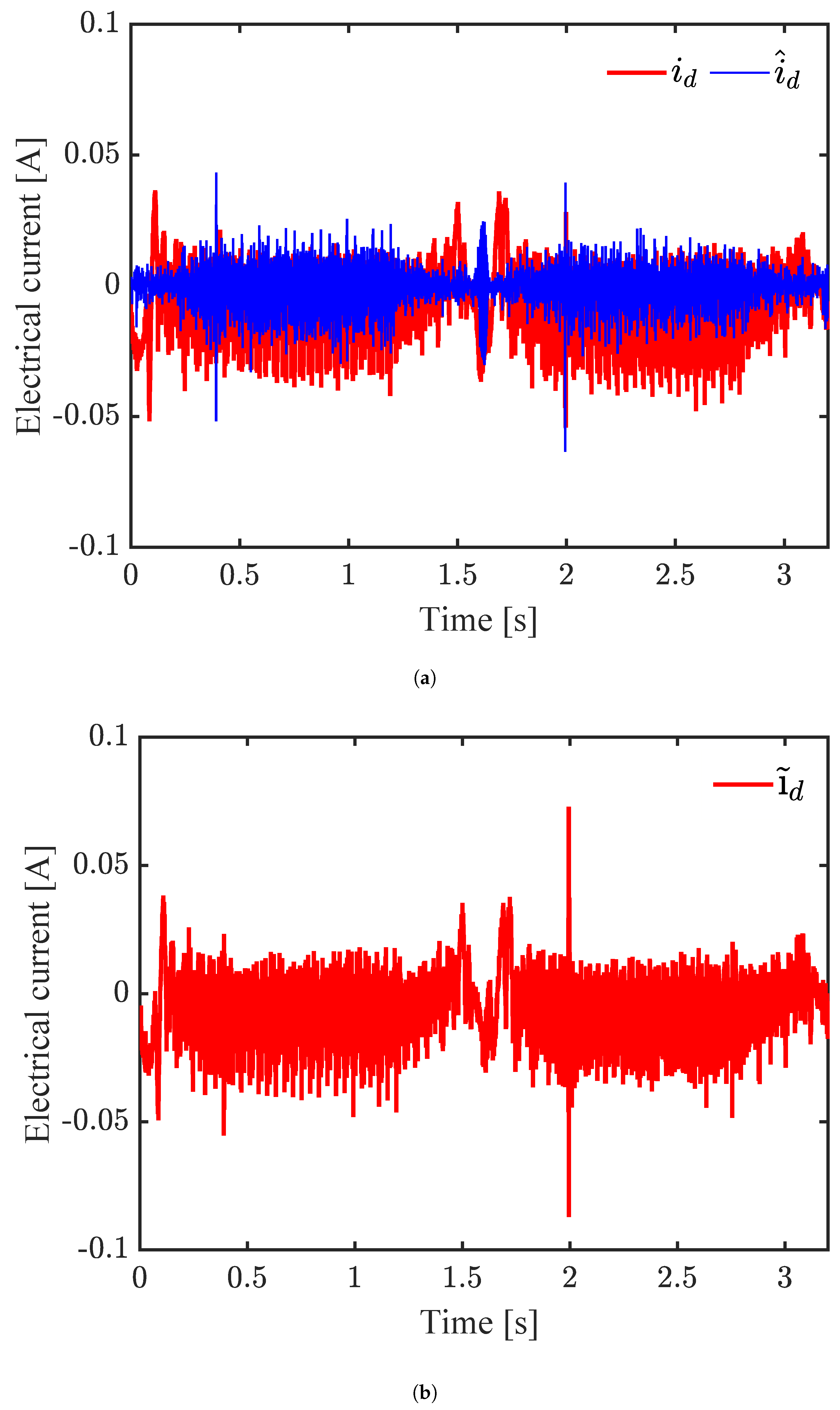
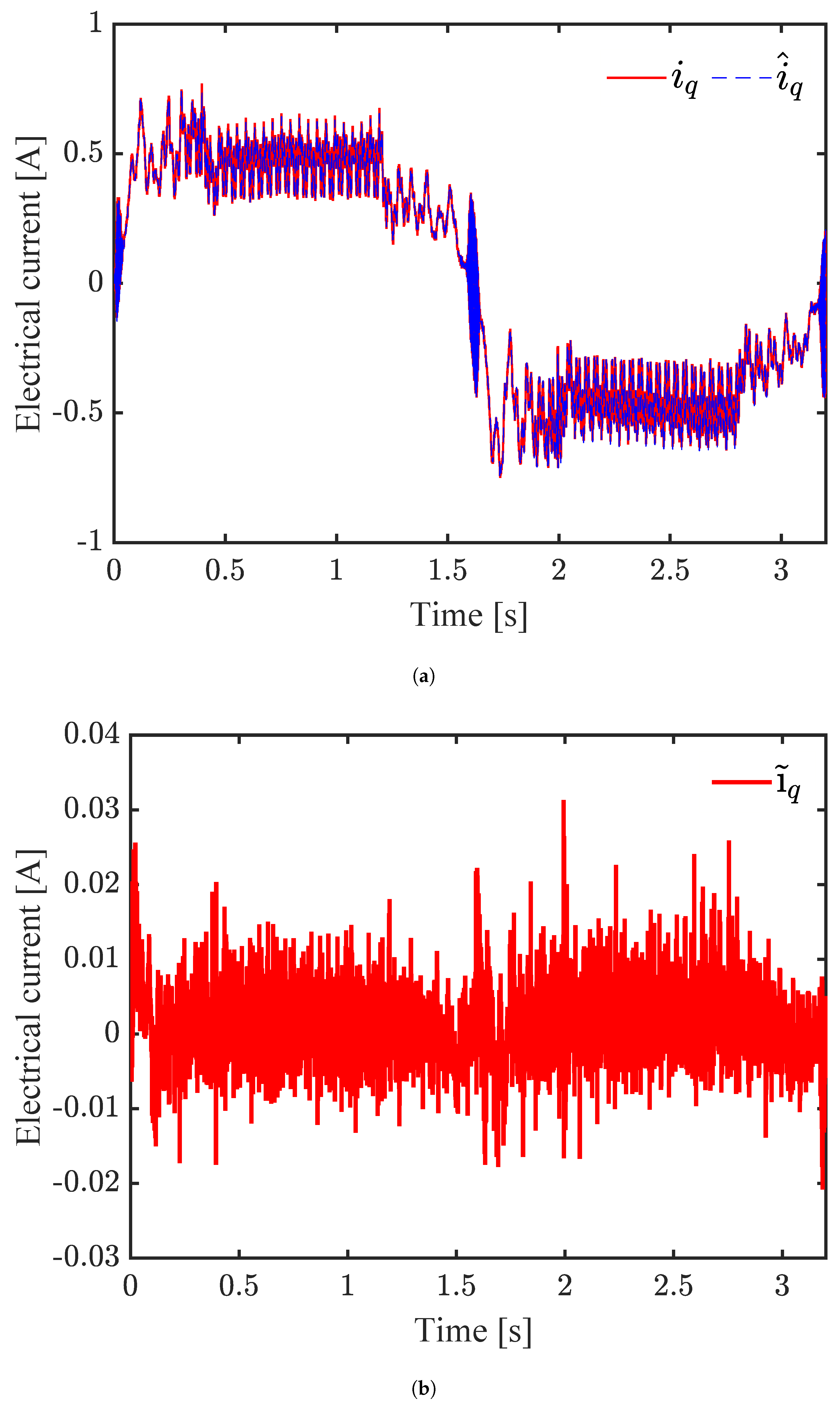
For instance, Figure 14 exhibits satisfactory performance estimation and control, with the current maintained close to zero. Furthermore, the variations in the magnitudes of the , , and signals exhibited similarity due to the proportional relationship between the component current q and electromagnetic torque, as illustrated in Figure 12 and Figure 15a. Finally, satisfactory error estimation performance was achieved without major difficulties, as illustrated in Figure 14b and Figure 15b.
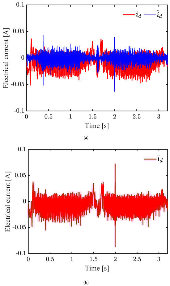
Figure 14.
Experimental results: PMSM controller system with proposed sensorless control scheme under load torque variations. (a) Stator current , (b) current error estimation performance.
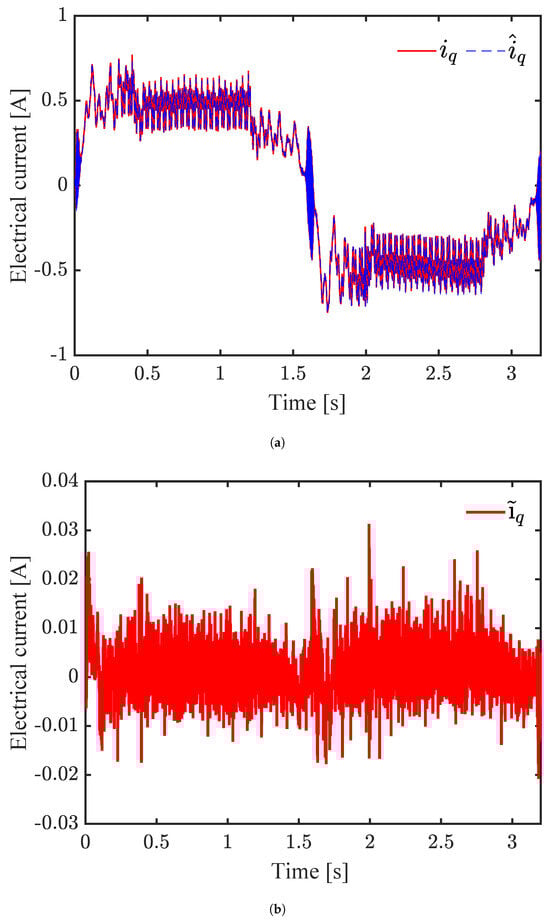
Figure 15.
Experimental results: PMSM controller system with proposed sensorless control scheme under load torque variations. (a) Stator current , (b) current error estimation performance.
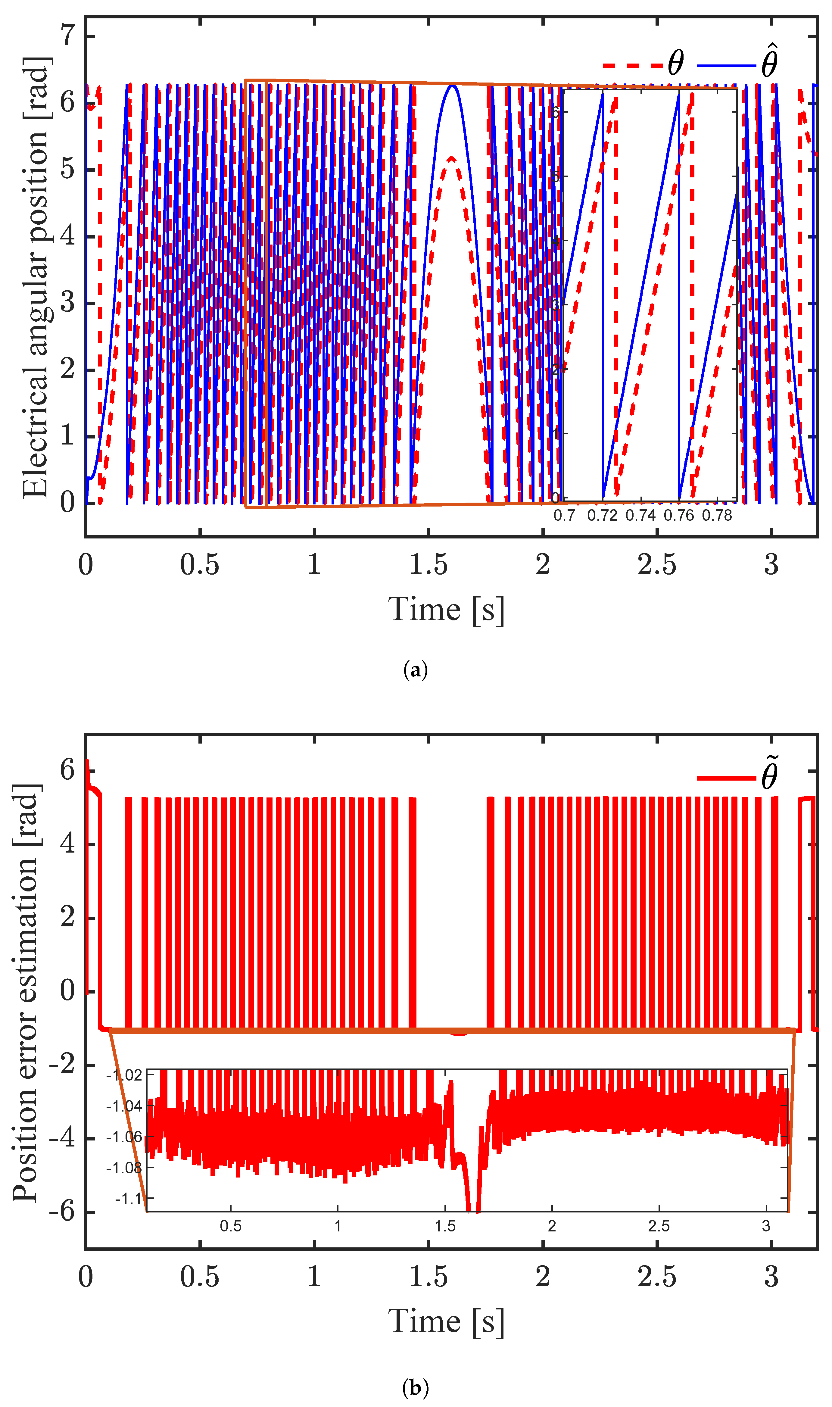
Figure 16a illustrates the rotor position signals obtained from the incremental encoder and the observer. The magnitude of the phase shift between the signals is illustrated in Figure 16b as the position error. A zoomed-in view along the error signal reveals an average amplitude consistent with the initial misalignment according to Equation (54). This result indicates that the proposed observer compensates for the initial error, accurately estimating the electrical position.
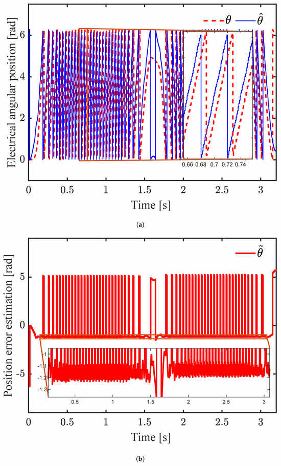
Figure 16.
Experimental results: PMSM controller system with proposed sensorless control scheme under load torque variations. (a) Measured and estimated rotor position, (b) position error estimation.
Table 2 compares the Mean Absolute Error (MAE) and Mean Square Error (MSE) performance from the experimental tests described in this section with those from experiments utilizing a sensorless control algorithm based on the observer from [28], which essentially designs an ESO interconnected with a PI to estimate the load torque and control the speed trajectory of a PMSM. Table 2 shows that our scheme improves the estimation accuracy of the observer variables.
Table 2.
Indexes of MAE and MSE estimation.
When studying the model in Equation (9), it is clear that the electrical dynamics of the motor will be affected by an excessive back electromotive force that will increase as the position error grows. From a control perspective, this overload in the windings could force the solutions to deviate from the reference trajectory, which could affect the relative stability of the system, as shown by the underdamped transients at the beginning and zero-crossing in Figure 13 and Figure 14.
However, the bound defined in the stability analysis indicates that, as long as the PMSM is subjected to external load torques and is operating within its physical limits, the observer solutions will converge and remain within an attraction region, , in Equation (45) in such a way that the angular misalignment is corrected, as shown by the temporal position signal in Figure 16. Therefore, the proposed sensorless scheme achieves acceptable control operation, as shown by the simulations and experiments of this work.
Although it is well known that in sensorless applications the motors operate at speeds where the back electromotive force current can occur, the methodology proposed in this research is suggested to be helpful in applications where the alignment of the stator and rotor magnetic fields is not successfully achieved due to high static inertia.
7. Conclusions
An extended state observer combined with an electrical angular position estimator has been developed to address the sensorless speed tracking problem for surface-mounted PMSMs. The electrical variables are the only measurements for feedback. To enhance the control performance, the proposed observer accurately estimates the rotor position by correcting the offset error resulting from misalignment. Moreover, the observer provides an efficient approach for estimating load torque time variations.
The present research introduces a model based on the rotatory reference frame and the offset angle. Through Lyapunov stability analysis and considering the physical operation domain of the PMSM, we established sufficient conditions to ensure that the trajectories of the observer error remain uniformly bounded solutions, despite variations in the load torque affecting the motor. The simulation and experiments performed validated the effectiveness of the proposed scheme.
In future work, our goal is to introduce an enhanced controller to further improve reliability and accuracy in the presence of unmodeled dynamics and/or parametric variations.
Author Contributions
Conceptualization, R.R.-V. and L.N.C.; formal analysis, C.A.-M., R.R.-V. and L.N.C.; investigation, L.N.C. and P.A.V.; methodology, C.A.-M., R.R.-V. and P.A.V.; resources, R.R.-V. and L.N.C.; validation, C.A.-M., R.R.-V. and L.N.C.; writing—original draft, C.A.-M., R.R.-V. and L.N.C.; writing—review and editing, L.N.C. and P.A.V. All authors have read and agreed to the published version of the manuscript.
Funding
This research was funded by Tecnológico Nacional de México (TecNM) research projects. In addition, this work was performed within the research group ITTIJ-CA-10: “SISTEMAS DINÁMICOS NO LINEALES” and the international network “Red internacional de control y cómputo aplicados”, both funded by the TecNM.
Data Availability Statement
The original contributions presented in this study are included in the article. Further inquiries can be directed to the corresponding authors.
Conflicts of Interest
The authors declare that they have no conflicts of interest.
References
- Abdelrauf, A.A.; Saad, W.W.; Hebala, A.; Galea, M. Model Predictive Control Based PID Controller for PMSM for Propulsion Systems. In Proceedings of the 2018 IEEE International Conference on Electrical Systems for Aircraft, Railway, Ship Propulsion and Road Vehicles & International Transportation Electrification Conference (ESARS-ITEC), Nottingham, UK, 7–9 November 2018; pp. 1–7. [Google Scholar] [CrossRef]
- Rauth, S.S.; Kastha, D.; Bajpai, P. A sensorless control strategy for automatic start-up and grid-synchronization of doubly fed induction generator in wind energy conversion system. Int. J. Circuit Theory Appl. 2024, 52, 1733–1753. [Google Scholar] [CrossRef]
- Zhang, D.; Zhang, H.; Li, X.; Zhao, H.; Zhang, Y.; Wang, S.; Ahmad, T.; Liu, T.; Shuang, F.; Wu, T. A PMSM Control System for Electric Vehicle Using Improved Exponential Reaching Law and Proportional Resonance Theory. IEEE Trans. Veh. Technol. 2023, 72, 8566–8578. [Google Scholar] [CrossRef]
- Benevieri, A.; Carbone, L.; Cosso, S.; Kumar, K.; Marchesoni, M.; Passalacqua, M.; Vaccaro, L. Surface Permanent Magnet Synchronous Motors’ Passive Sensorless Control: A Review. Energies 2022, 15, 7747. [Google Scholar] [CrossRef]
- Li, J.; An, H.; Lu, Y.; Hou, Q.; Deng, W.; Wang, S. On the sensorless synchronous direct drive control of permanent magnet motor for three-blade roots vacuum pump. Energy Rep. 2023, 9, 828–837. [Google Scholar] [CrossRef]
- Bi, G.; Zhang, G.; Wang, Q.; Ding, D.; Li, B.; Wang, G.; Xu, D. High-Frequency Injection Angle Self-Adjustment Based Online Position Error Suppression Method for Sensorless PMSM Drives. IEEE Trans. Power Electron. 2023, 38, 1412–1417. [Google Scholar] [CrossRef]
- Li, Y.; Hu, H.; Shi, P. A Review of Position Sensorless Compound Control for PMSM Drives. World Electr. Veh. J. 2023, 14, 34. [Google Scholar] [CrossRef]
- Jung, T.U.; Jang, J.H.; Park, C.S. A Back-EMF Estimation Error Compensation Method for Accurate Rotor Position Estimation of Surface Mounted Permanent Magnet Synchronous Motors. Energies 2017, 10, 1160. [Google Scholar] [CrossRef]
- Ye, S.; Yao, X. An Enhanced SMO-Based Permanent-Magnet Synchronous Machine Sensorless Drive Scheme With Current Measurement Error Compensation. IEEE J. Emerg. Sel. Top. Power Electron. 2021, 9, 4407–4419. [Google Scholar] [CrossRef]
- Sangeeth, P.; Ramalingam, B.; Ashok, S. Effective Saliency Based Initial Rotor Position Estimation of Permanent Magnet Synchronous Motor for High torque applications. In Proceedings of the 2020 IEEE International Power and Renewable Energy Conference, Karunagappally, India, 30 October–1 November 2020; pp. 1–6. [Google Scholar] [CrossRef]
- Kim, D.; Kim, J.; Lim, H.; Park, J.; Han, J.; Lee, G. A Study on Accurate Initial Rotor Position Offset Detection for a Permanent Magnet Synchronous Motor Under a No-Load Condition. IEEE Access 2021, 9, 73662–73670. [Google Scholar] [CrossRef]
- Yoo, J.; Lee, J.; Sul, S.K. Analysis of Instability in Torque Control of Sensorless PMSM Drives in Flux Weakening Region. IEEE Trans. Power Electron. 2021, 36, 10815–10826. [Google Scholar] [CrossRef]
- Lara, J.; Xu, J.; Chandra, A. Effects of Rotor Position Error in the Performance of Field-Oriented-Controlled PMSM Drives for Electric Vehicle Traction Applications. IEEE Trans. Ind. Electron. 2016, 63, 4738–4751. [Google Scholar] [CrossRef]
- Liu, G.; Zhang, H.; Song, X. Position-Estimation Deviation-Suppression Technology of PMSM Combining Phase Self-Compensation SMO and Feed-Forward PLL. IEEE J. Emerg. Sel. Top. Power Electron. 2021, 9, 335–344. [Google Scholar] [CrossRef]
- Rahman, S.U.; Xia, C. Rotor Speed and Position Estimation Analysis of Interior PMSM Machines in Low and Medium-High Speed Regions Adopting an Improved Flux Observer for Electric Vehicle Applications. Machines 2023, 11, 574. [Google Scholar] [CrossRef]
- Jiang, T.; Ni, R.; Gu, S.; Wang, G. A Study on Position Estimation Error in Sensorless Control of PMSM Based on Back EMF Observation Method. In Proceedings of the 2021 24th International Conference on Electrical Machines and Systems (ICEMS), Gyeongju, Republic of Korea, 31 October–3 November 2021; pp. 1999–2003. [Google Scholar] [CrossRef]
- Ding, H.; Zou, X.; Li, J. Sensorless Control Strategy of Permanent Magnet Synchronous Motor Based on Fuzzy Sliding Mode Observer. IEEE Access 2022, 10, 36743–36752. [Google Scholar] [CrossRef]
- Xu, W.; Qu, S.; Zhang, H. A composite sliding-mode observer with PLL structure for a sensorless SPMSM system. Int. J. Electr. Power Energy Syst. 2022, 143, 108510. [Google Scholar] [CrossRef]
- Novak, Z.; Novak, M. Adaptive PLL-Based Sensorless Control for Improved Dynamics of High-Speed PMSM. IEEE Trans. Power Electron. 2022, 37, 10154–10165. [Google Scholar] [CrossRef]
- Hou, Q.; Ding, S.; Dou, W.; Jiang, L. Estimated Position Error Suppression Using Quasi-Super-Twisting Observer and Enhanced Quadrature Phase-Locked Loop for PMSM Sensorless Drives. IEEE Trans. Circuits Syst. II Express Briefs 2024, 71, 3865–3869. [Google Scholar] [CrossRef]
- Chen, L.; Jin, Z.; Shao, K.; Wang, H.; Wang, G.; Iu, H.H.C.; Fernando, T. Sensorless Fixed-Time Sliding Mode Control of PMSM Based on Barrier Function Adaptive Super-Twisting Observer. IEEE Trans. Power Electron. 2024, 39, 3037–3051. [Google Scholar] [CrossRef]
- Aguilar, L.T.; Ramírez-Villalobos, R.; Ferreira de Loza, A.; Coria, L.N. Robust sensorless speed tracking controller for surface-mount permanent magnet synchronous motors subjected to uncertain load variations. Int. J. Syst. Sci. 2020, 51, 35–48. [Google Scholar] [CrossRef]
- Cai, J.; Gu, Y.; David Cheok, A.; Yan, Y. A Survey of Phase-Locked Loop Technologies in Sensorless Position Estimation of Permanent Magnet Synchronous Motor Drives. IEEE Trans. Instrum. Meas. 2024, 73, 1–16. [Google Scholar] [CrossRef]
- Kuruppu, S.S.; Zou, Y. Post Production PMSM Position Sensor Offset Error Quantification via Voltage Estimation. In Proceedings of the 2020 IEEE Energy Conversion Congress and Exposition (ECCE), Detroit, MI, USA, 11–15 October 2020; pp. 3355–3361. [Google Scholar] [CrossRef]
- Chi, W.C.; Cheng, M.Y. Implementation of a sliding-mode-based position sensorless drive for high-speed micro permanent-magnet synchronous motors. ISA Trans. 2014, 53, 444–453. [Google Scholar] [CrossRef] [PubMed]
- Kim, H.; Bhattacharya, S. Improved Rotor Position Estimation in Extended Back-EMF Based Position Sensorless Control for IPMSMs with Non-Sinusoidal Back-EMF. In Proceedings of the 2020 IEEE Industry Applications Society Annual Meeting, Detroit, MI, USA, 10–16 October 2020; pp. 1–7. [Google Scholar] [CrossRef]
- Zuo, Y.; Ge, X.; Zhang, S.; Cao, H.; Wang, H.; Wang, Y.; Lee, C.H.T. Sensorless Control of IPMSM Drives Based on Extended State Observer With Enhanced Position Estimation Accuracy. IEEE Trans. Power Electron. 2025, 40, 787–800. [Google Scholar] [CrossRef]
- Aldrete-Maldonado, C.; Ramirez-Villalobos, R.; Coria, L.N.; Plata-Ante, C. Sensorless Scheme for Permanent-Magnet Synchronous Motors Susceptible to Time-Varying Load Torques. Mathematics 2023, 11, 3066. [Google Scholar] [CrossRef]
- Wang, H.; Lu, K.; Wang, D.; Blaabjerg, F. Online Identification of Intrinsic Load Current Dependent Position Estimation Error for Sensorless PMSM Drives. IEEE Access 2020, 8, 163186–163196. [Google Scholar] [CrossRef]
- Kelly, R.; Santibáñez, V.; Loría, A. Control of Robot Manipulators in Joint Space; Springer: Berlin/Heidelberg, Germany, 2005; Volume 693. [Google Scholar]
- Yu, W. Luenberger observer design for uncertainty nonlinear systems. In New Perspectives and Applications of Modern Control Theory; Springer: Berlin/Heidelberg, Germany, 2018; pp. 25–42. [Google Scholar]
- Apte, A.; Joshi, V.A.; Mehta, H.; Walambe, R. Disturbance-Observer-Based Sensorless Control of PMSM Using Integral State Feedback Controller. IEEE Trans. Power Electron. 2020, 35, 6082–6090. [Google Scholar] [CrossRef]
- Bist, A.; Jadhav, S.V. Sensorless Control based on Sliding Mode Observer for PMSM drive. In Proceedings of the 2020 IEEE International Conference on Power Electronics, Drives and Energy Systems (PEDES), Jaipur, India, 16–19 December 2020; pp. 1–6. [Google Scholar] [CrossRef]
- Huang, X.; Yang, M.; Ren, B.; Chai, N.; Xu, D. Angle misalignment detection and its suppression algorithm in rotor system based on speed signal. In Proceedings of the 2020 IEEE 9th International Power Electronics and Motion Control Conference (IPEMC2020-ECCE Asia), 29 November–2 December 2020; pp. 3174–3179. [Google Scholar] [CrossRef]
- Lian, C.; Xiao, F.; Liu, J.; Gao, S. Analysis and compensation of the rotor position offset error and time delay in field-oriented-controlled PMSM drives. IET Power Electron. 2020, 13, 1911–1918. [Google Scholar] [CrossRef]
- Campos, P.J.; Coria, L.N.; Trujillo, L. Nonlinear speed sensorless control of a surface-mounted PMSM based on a Thau observer. Electr. Eng. 2018, 100, 177–193. [Google Scholar] [CrossRef]
- Phanomchoeng, G.; Rajamani, R. Observer Design for Lipschitz Nonlinear Systems Using Riccati Equations. In Proceedings of the 2010 American Control Conference, Baltimore, MD, USA, 30 June–2 July 2010. [Google Scholar]


Disclaimer/Publisher’s Note: The statements, opinions and data contained in all publications are solely those of the individual author(s) and contributor(s) and not of MDPI and/or the editor(s). MDPI and/or the editor(s) disclaim responsibility for any injury to people or property resulting from any ideas, methods, instructions or products referred to in the content. |
© 2025 by the authors. Licensee MDPI, Basel, Switzerland. This article is an open access article distributed under the terms and conditions of the Creative Commons Attribution (CC BY) license (https://creativecommons.org/licenses/by/4.0/).