Article

A Collaborative Design Method for the Cylindrical Gear Paired with Skived Face Gears Driven by Contact Performances

by
Zhenyu Zhou
1,2,
Yuanyuan Zhang
3,4,
Mou Li
1,
Yuansheng Zhou
2,5,*,
Zhongwei Tang
2,
Jinyuan Tang
2,5 and
Liang Zhou
6
1
AECC Hunan Aviation Powerplant Research Institute, Zhuzhou 412002, China
2
College of Mechanical and Electrical Engineering, Central South University, Changsha 410083, China
3
AECC Zhongchuan Transmission Machinery Co., Ltd., Changsha 410200, China
4
School of Mechanical Engineering, Shanghai Jiao Tong University, Shanghai 200240, China
5
State Key Laboratory of Precision Manufacturing for Extreme Service Performance, Central South University, Changsha 410083, China
6
State Grid Loudi Power Supply Company, Loudi 417000, China
*
Author to whom correspondence should be addressed.
Mathematics 2025, 13(7), 1180; https://doi.org/10.3390/math13071180
Submission received: 10 March 2025 / Revised: 26 March 2025 / Accepted: 28 March 2025 / Published: 3 April 2025

Abstract

:
Skiving is an efficient method for manufacturing face gears, but theoretical machining errors may occur when face gears designed for shaping or grinding are processed by skiving. This study presents a face gear directly designed for the skiving process, eliminating theoretical machining errors. Additionally, a new design approach for the cylindrical gear is proposed to pair with this face gear. The tooth surface models of both the cylindrical pinion and face gear are established. For the pinion, surface modifications are applied in both profile and longitudinal directions, while the face gear’s tooth surface model is tailored for the skiving process to avoid theoretical machining errors. The contact performance, including transmission error, contact stress, and contact pattern, is evaluated through Tooth Contact Analysis (TCA). An optimization model is developed to identify the optimal cylindrical gear tooth surface parameters, targeting improved contact performance. The proposed method is validated by a case study, which shows that the optimized face gear transmission results in lower maximum contact stress and reduced transmission error amplitude.
MSC:
70B15; 74M10; 90C90

1. Introduction

In gear manufacturing, the pursuit of efficiency and environmental sustainability has guided recent advancements toward the utilization of high-performance gear skiving processes. Traditionally focused on cylindrical gears, these practices are now being extended to machining face gears. This adaptation is influenced by the fundamental challenges associated with face gear fabrication, prominently the inherent errors arising from their geometric complexity. Consequently, efforts to refine the precision of face gears have concentrated on two pivotal aspects: cutting tool design and the optimization of tool path.
In terms of cutting-edge optimization, Chen established a computational framework characterizing the front face derived from the design and manufacturing process [1] and a computational framework of the main back face derived from the error-free design [2]. Guo and his colleagues used the B spline curve to represent the tool profile and derived the sensitivity matrix, which made the scraped tooth surface approximate the theoretical tooth surface by adjusting the polynomial coefficients [3]. They also developed a skiving model for machining involute cylindrical gears and corrected the tooth profile error of the involute cylindrical gears by adjusting the machine setup parameters [4]. Guo et al. conducted a theoretical analysis of conventional tools for gear machining and investigated the effect of the tool lead angle on the tooth profile error [5]. Tisa proposed a mathematical modeling method compatible with simple power skiving tools and general power skiving tools [6], and later presented a straightforward but thorough mathematical modeling method for product development workflows and industrial fabrication considerations of cutting interference-free power skiving tools [7], and analyzed that when the identical power scraping tool cuts various parameters gears, the effect of reducing the number of gear teeth (or helix angle) on the tooth shape error is greater than increasing the number of gear teeth (or helix angle) [8]. Moriwaki et al. considered the effect of tool parameters such as material removal depth, rake angle, and local rake angle along the cutting edge on the amount of tooth flank offset [9]. Shih and Li put forward a novel design approach for conical skiving tools and constructed a mathematical model for the error-free rake face, leveraging the cutting edges situated on the rake face, which stem from a spreading gears with gradually decreasing tooth profile variance coefficients [10]. Thomas provides a coordinate system for the skiving simulation and illustrates the gear skiving kinematics and simulation algorithms [11]. Wang et al. compare the effects of flat and curved faces on machining accuracy in circular gear machining [12]. Hoang et al. optimize the asymmetric rack profile using linear equations based on grinding allowance with iterative compensation to design a new mathematical model of scraping tool considering the grinding allowance [13]. Luu and Wu utilize a quadratic polynomial function to rectify the asymmetric rack profile, analytically ascertain the pressure angle, protrusion, and polynomial coefficients for both sides of the rack, based on the stipulated grinding allowance and the conjugate relationship between the gear and the tool, realizes the basic uniformity of the grinding allowance of the two tooth flanks after machining [14], and proposes a new method to obtain the tooth flanks of variable pressure and variable helix angle by using the same tool [15]. Han et al. present a mathematical model that determines the front and relief angles of an involute tool and calculates the tooth form error relative to the target gear. The distribution of tooth shape errors is then approximated using a fifth-degree polynomial. Finally, these errors are corrected by using a polynomial function to adjust the tool profile [16]. Guo et al. developed an innovative geometric modeling framework for rotary milling cutter systems through kinematic analysis. Their methodology derives the geometric precision of scraping tool cutting edges by analyzing spatial intersection loci between complementary flank surfaces and the tool’s rake face geometry, incorporating an axial offset configuration relative to the rotational centerline [17]. Olivoni et al. investigated the sensitivity of tools with different parameters to the variation of the cutting profile and proposed a process strategy to standardize the machining efficiency of the tool during its utilization [18].
In terms of path optimization, Ding et al. proposed an error compensation method based on a spatial precision prediction model. This method amends the NC turning code in line with the anticipated spatial error, thereby diminishing the tooth profile deviation [19]. Ren et al. elucidated the relationship between the eccentricity error and the gear tooth profile by means of numerical simulation [20] and proposed a parametric modeling method for calculating the unchipped geometry [21]. Han et al. explored and compiled the impact of tool tooth number and helix angle on meshing performance [22]. Han analyzed the installation and movement of non-orthogonal gears on a six-axis machine, determined the machining parameters, and put forward a technique for generating tooth flank profiles on a six-axis machine by adjusting the machining parameters [23]. Tsai proposed a new design method for cylindrical scraping tools by defining an appropriate front-face position to obtain the correct cutting-edge section [24]. Shih et al. provided a let-off angle by modifying the machine settings for the gear skiving process to avoid collision and finally obtained a new error-free cylindrical scraping tool design [25]. Janßen et al. controlled the kinematic variables to selectively shape the gear tooth flanks [26]. Using the method of successive shifting and trimming, Xu and his team formulated a mathematical model for face gear teeth and subsequently enhanced the tooth surface [27].
Part of the study used two optimization methods at the same time. Wang proposed an algorithm based on chaotic mapping by establishing a parameter optimization model with optimizing processing precision as the primary objective while maintaining operational productivity and preventing tool-path conflicts that constitute essential boundary conditions [28]. The principle behind tool design has been analyzed drawing upon the conjugate surface theory, and subsequently, a novel tool design approach has been put forward. Planar front cutting surface and curved front cutting surface. Then, the front and rear working angles were calculated and analyzed [29]. Guo investigated the impact of tool profile parameters on the structure of the face gear tooth surface and reduced the deviation of the face gear surface by adjusting the depth of cut, the rotation angle of the face gear, and the offset of the shaving cutter [30]. Lin et al. proposed and developed the PSO-BP-PSO algorithm through empirical geometric inaccuracy measurements, introduced the analysis of the global optimum, and conducted a comprehensive evaluation of the optimized parameters were comprehensively evaluated [31]. Hrytsay et al. modeled and investigated the gear skiving process drawing on the established geometric model of the unreformed chip, with consideration given to the shape and size of the previously formed tooth gap, and used the power shunt method, which lays the foundation for further optimization of the tooth surface afterward [32]. Tang and his colleagues modeled and studied the gear skiving process by optimizing the cutting-edge parameters and tool path parameters to minimize the theoretical machining error, then obtained the machining error by measurement and further implemented trajectory refinement through process sequence adjustments in subsequent manufacturing stages to achieve the effect of reducing the tooth face error [33]. Le et al. modeled the computational adjustment of CNC axial movement regulation and parametric adaptation of rack tool coefficients. By modifying the machine axes settings on the CNC machine, the altered tooth topology of the face gear was achieved [34]. Le et al. also employed nonlinear regression techniques combining the Levenberg-Marquardt optimization framework with gradient sensitivity analysis to iteratively determine multivariate polynomial parameters and optimize the cutting paths on the CNC machine in terms of the additional movements represented by the polynomials, completing the closed-loop optimization of the tooth flanks [35].
These endeavors, however, encounter substantial obstacles when contending with numerous variables. While higher precision machining could theoretically be achieved through higher-order curve fitting of the tool profile and toolpath, in practice, manufacturing tools based on these higher-order curves and executing the machining motions through CNC programming present certain challenges. These challenges are particularly significant when dealing with multi-axis machining movements, which place higher demands on both the tool manufacturing process and the machine tool itself.
Addressing these complexities, this paper introduces a novel performance-driven approach to the skiving of face gears using standard involute gear cutters initially designed for cylindrical gears. The key innovation lies in complementing this standard cutting process by meticulously designing a matching conjugate gear tooth surface that ensures optimal meshing performance. The advantages of adopting this method are twofold. Firstly, it significantly reduces the time required to design toolpaths for face gear skiving and lowers the costs associated with manufacturing high-order modified cutting tools and programming complex machine tool motions associated with the high-order modified tool path. Secondly, the manufacturing process of cylindrical gears is already well-established; therefore, machining specially designed tooth surfaces on cylindrical gears presents a simpler and more efficient alternative compared to direct manufacturing of face gears. It should be pointed out that this method can be used for situations where the relevant parameters of both the cylindrical gear and the face gear contain design variables, and this paper only takes the cylindrical gear as an example. The paper is structured as follows: Section 2 initially presents the mathematical models for the tooth surface of the modified pinion and the skived face gear. Then, a collaborating design method to the pinion which meshed with the skived face gear is proposed, and a corresponding optimization model is introduced in Section 3. Lastly, the proposed method and model are discussed and verified in Section 4.

2. The Mathematical Models of the Tooth Surfaces of the Face Gear Drives

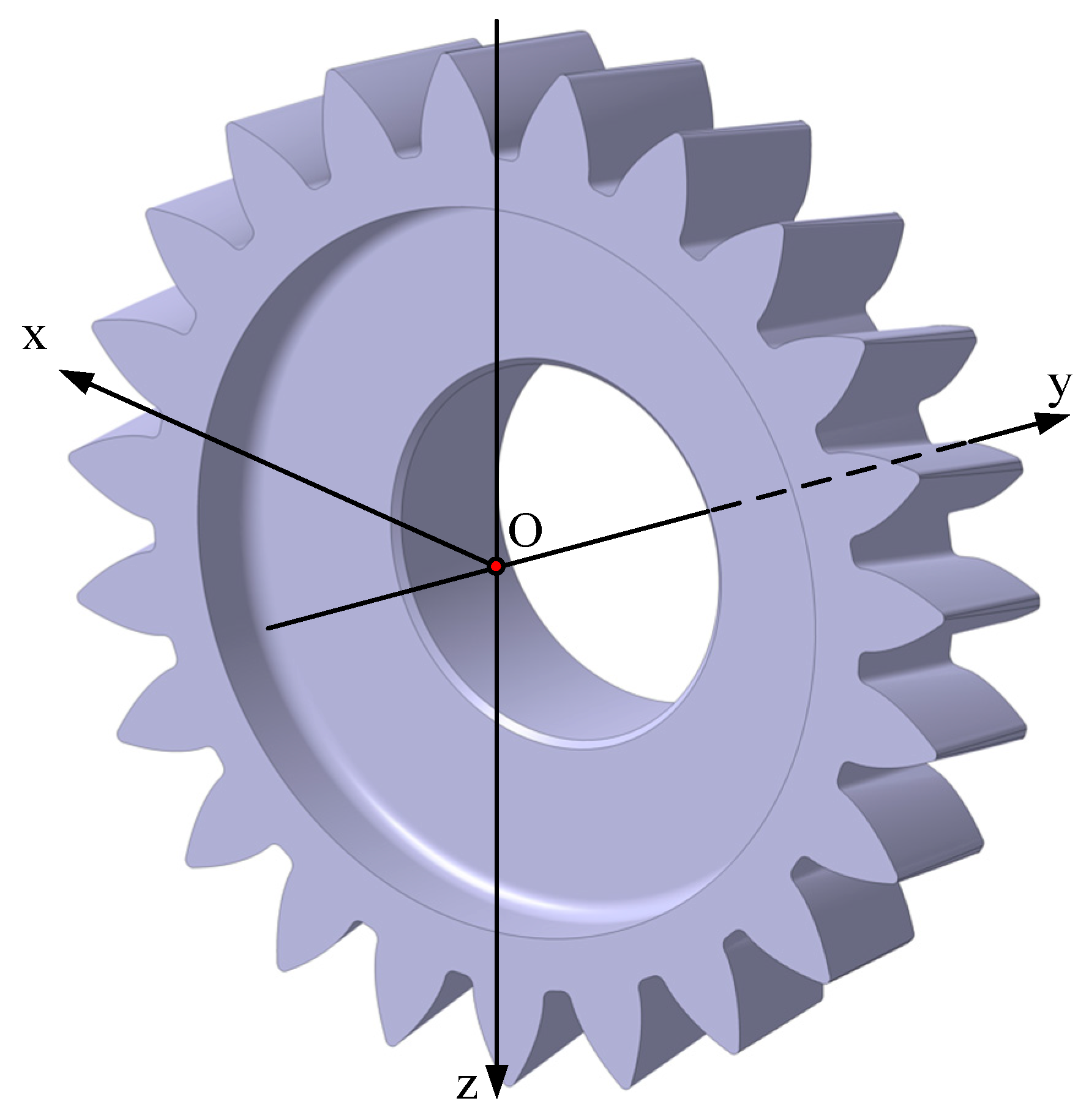
2.1. The Tooth Surface of the Modified Cylindrical Pinion

Spur gear is one of the most common gears in actual production and use. The specific modification tactic involves modifying the original tooth profile and tooth direction line, with the standard tooth surface as the basis. There are many ways to modify straight gear, such as tooth profile modification, tooth direction modification, helix modification, etc., through these modification methods, the contact stress, contact degree, and transmission error are finally improved [36]. This paper adopts a comprehensive method of tooth profile modification combined with tooth direction modification, as shown in Figure 1.
Accordingly, the modification value can be calculated by
Δ d b , r = Δ p r + Δ l b n
where n represents the normal vector of the tooth surface of the standard spur gear. The surface of the modified cylindrical gear with comprehensive modification can be conveyed as
r p m r , b , θ s = r p s θ s , b + Δ d b , r
where r p s (θs) describes the vector of the tooth surface on the standard cylindrical gear, and it is written as
r p s θ s , b = ± r b s sin θ s θ s 0 r b s θ s cos θ s θ s 0 r b s cos θ s θ s 0 + r b s θ s sin θ s θ s 0 b 1
rbs represents the base circle radius of the cylindrical pinion, and θs describe the position of this point on the tooth profile.

2.2. The Tooth Surface of the Skived Face Gears

A machined surface is typically described by the cutter’s envelope surface’s mathematical description, which results from its motion relative to the work piece during the machining process. This paper begins by outlining the skiving process for spur face gear drives, built on this concept. After detailing the cutter edge geometry and the associated kinematic chain, it establishes the mathematical models for the tooth surfaces of face gears created through the skiving method.

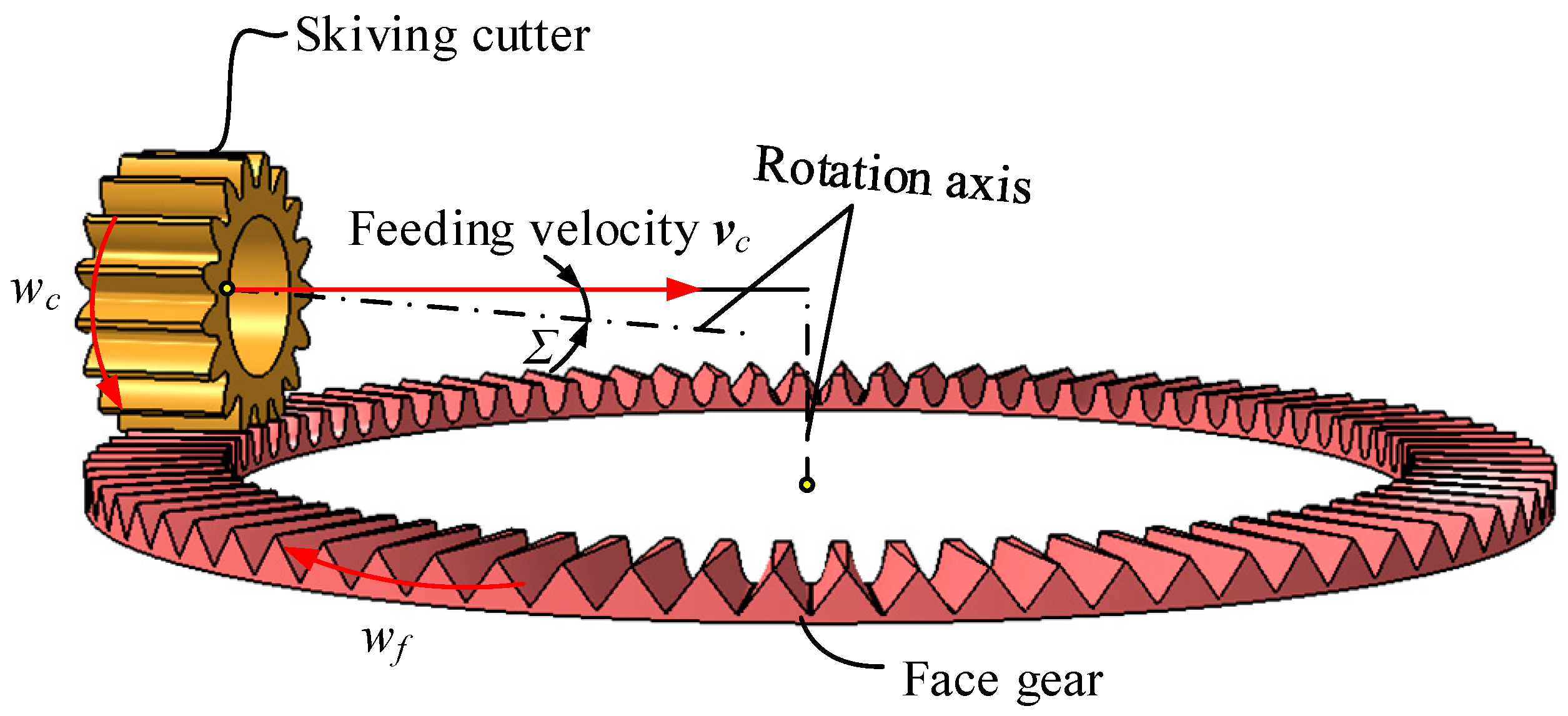
2.2.1. The Skiving Process of Spur Face Gear Drives

Previous studies have thoroughly examined the mechanism of spur face gear skiving. During the skiving process, the tooth profile is formed as the cutter and the workpiece operates at prescribed angular rates, as shown in Figure 2. To produce the full width of the skived gear teeth, a feed velocity vc is applied to the skiving cutter (or work piece), directed along the tooth width. Unlike gear shaping, which involves a cutting velocity aligned with the cutter’s rotational axis, skiving requires an axis-crossing angle Σ between the cutter’s axis and its feed velocity. And wc and wf denote the angular velocities of the skiving tool and the face gear. The correlation between these two angular velocities is able to be outlined in the following equation.
w f / w c = N c / N f = i c f
Nc is the tooth number of the skiving cutter and the pinion, and the Nf corresponds to the number of teeth on the face gear. The icp and icf represent the gear ratio.
Grounded in the kinematic principles of face gear skiving, the two parameters envelope surface of the skiving cutter is portrayed as follows.
r f : r f ( ψ c , θ c , l f ) = M f c ( ψ c , l f ) r c θ c ( a ) f ( ψ c , θ c , l f ) = r f ψ c × r f θ c r f l f = 0 ( b )
where Mfc(ψc, lf) is the coordinate transformation matrixes from the skiving cutter to the face gear. The function f(ψc, θc, lf) defines the engagement equation of the skiving cutter and the work piece. By solving this meshing equation and substituting it into the first equation of Equation (5), the face gear flank can be simplified and expressed in terms of two variables as follows.
r f l f , θ c = r f x l f , θ c r f y l f , θ c r f z l f , θ c 1 T

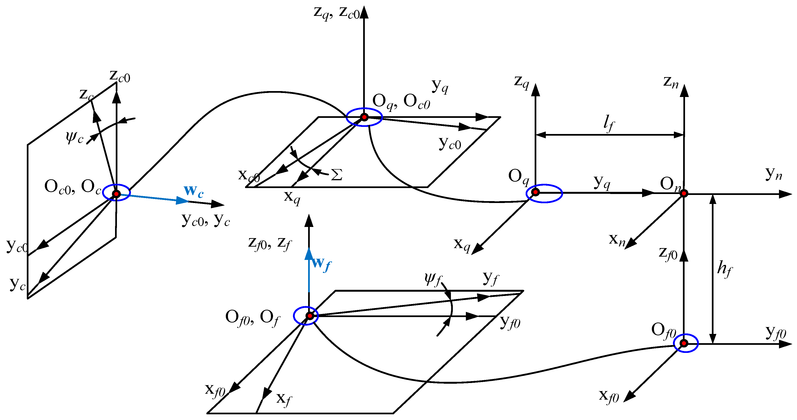
2.2.2. The Kinematic Chain of Gear Skiving Processes

As stated by the kinematics of the face gear depicted in Figure 2, the coordinate systems are defined as depicted in Figure 3. Sf(xf, yf, zf) and Sc(xc, yc, zc) are fixed to the face gear and the skiving cutter, respectively. The initial position coordinate systems Sf0(xf0, yf0, zf0) and Sc0(xc0, yc0, zc0) represent the face gear and skiving cutter at the starting point where their rotational angles about their respective axes are zero. Additionally, Sm(xm, ym, zm) and Sn(xn, yn, zn) represent the auxiliary coordinate systems used for further reference in the kinematic analysis.
The angle Σ denotes the angle formed by the cutter’s axis and the direction of feed, influencing the motion of the cutter relative to the face gear. The hf indicates the axial deviation in the axis of the face gear, it can be determined to
h f = m c N c / 2 / cos β c
lf denotes the distance between the skiving cutter and the rotation axis of the face gear in the feed direction. The angles ψc and ψf correspond to the angles through which the skiving cutter and the face gear rotate about their respective axes of rotation. These angles must adhere to specific rules defined for the skiving process as follows:
ψ f / ψ c = i c f
Subsequentially, the coordinate transformation matrix from the coordinate system Sc(xc, yc, zc) to Sf(xf, yf, zf) can be gained.
M f c = M f f 0 M f 0 n M n q M q c 0 M c 0 c
where
M f f 0 ψ f = cos ψ f sin ψ f 0 0 sin ψ f cos ψ f 0 0 0 0 1 0 0 0 0 1
M f 0 n h f = 1 0 0 0 0 1 0 0 0 0 1 h f 0 0 0 1
M n q l f = 1 0 0 0 0 1 0 l f 0 0 1 0 0 0 0 1
M q c 0 Σ = cos Σ sin Σ 0 0 sin Σ cos Σ 0 0 0 0 1 0 0 0 0 1
M c 0 c ψ c = cos ψ c 0 sin ψ c 0 0 1 0 0 sin ψ c 0 cos ψ c 0 0 0 0 1

2.2.3. The Representation of the Cutting Edges of the Skiving Cutter

The cutting edges of this cutter are typically designed in the shape of an involute, as shown in Figure 4, as described below.
r c θ c = r b c cos θ c θ c 0 + r b c θ c sin θ c θ c 0 0 ± r b c sin θ c θ c 0 r b c θ c cos θ c θ c 0 1
where
θ c 0 = tan α α + π / 2 / N c
rbc represents the base circle, and it can be gained by
r b c = m N c cos α / 2
m represents the modules, Nc is the tooth number, and α is the pressure angle of the skiving cutter.

3. Optimization Modeling of Tooth Surface Contact Performance of Face Gear Drives

3.1. Optimization Model Framework

The optimization framework developed for improving the interaction quality of the gear pair involves a structured methodology that integrates the optimization of design parameters with rigorous performance evaluation. This section delineates the core components of the framework, elucidating the sequential steps involved in the optimization process.
(1)
Problem Formulation
The initial phase of the optimization framework necessitates a precise definition of the objective function and associated constraints. The primary objective function is formulated to minimize the maximum contact stress while ensuring that the transmission error remains within predefined acceptable limits. Mathematically, the objective function is articulated as follows:
min f X = min P 0 X
where P0 denotes the maximum contact stress as a function of the design factors X of the pinion’s tooth surface, and it can be calculated by Equation (41) in Section 3.2.2.
(2)
Design Variables
The design variables within this optimization framework comprise four critical parameters that characterize the geometrical features of the pinion’s tooth surface as mentioned in Section 2.1. These parameters are meticulously selected to influence the contact conditions and overall performance. The design variables are represented as:
X = a r f d b r b d T
where each component of X corresponds to a specific design parameter as indicated in Section 2.1.
(3)
Constraints
The optimization process is subject to a series of constraints that must be satisfied to ensure a feasible solution:
(1)
Edge Contact Constraint: An evaluative method is employed to ascertain the occurrence of edge contact in Section 3.2.3. The outcome of this assessment dictates whether the optimization process proceeds or an alternative set of design parameters is explored. In the gear design process, avoiding edge contact is an important evaluation criterion. This is because edge contact leads to localized stress concentration, which severely reduces the reliability and durability of the gear transmission. Therefore, before calculating performance indicators such as contact stress and transmission error, it is necessary to determine whether edge contact occurs. If edge contact does not occur, it indicates that the set of parameters is suitable, and we can continue with the calculations. However, if edge contact is present, subsequent calculations would be meaningless.
(2)
Transmission Error Constraint: The transmission error δ can be calculated by Equation (24) in the following Section 3.2.1, and it must reside within a predetermined range δ0:
δ < δ 0
(4)
Optimization Algorithm and Iterative Process
Many algorithms can be adopted for this optimization problem, including gradient-based methods, genetic algorithms, or particle swarm optimization, contingent upon the function’s complexity and the constraints’ nature. However, in the optimization problem of this paper, the premise of the maximum contact stress calculation formula is that no edge contact occurs, so the edge contact should be determined before and after parameter optimization. Therefore, this paper adopts the method of multiple grid search. The specific iterative steps are described below.
(I) Rough dispersion: Initially, the variable space is discretized coarsely based on the given ranges (XL and XU) for each variable. At each discrete point, the edge contact condition is evaluated.
X X L X U
(II) Refined dispersion: Points that do not exhibit edge contact are selected to form a refined search space. This refined space undergoes further discretization, and the edge contact condition is reassessed. If no edge contact occurs, the corresponding contact stress and transmission error are computed. This process is repeated iteratively, with each iteration involving a finer discretization of the search space, until the discretization density Δ falls below a specified threshold Δ0.
Δ = X 1 X 2
where X1 and X2 are the sets of parameters corresponding to two adjacent discrete points in a discrete space.
(III) Output results: The objective is to identify the discrete point where the transmission error lies within the acceptable range δ0 and the contact stress is minimized. This point is then reported as the outcome of solving the optimization problem.
Throughout the iterations, the focus is on ensuring that the discretization is sufficiently fine to capture the nuances of the solution space while maintaining computational efficiency. The iterative refinement continues until the desired precision is achieved, ensuring that the solution is both accurate and optimal within the given tolerance.

3.2. Evaluation Criteria of the Contact Performance

3.2.1. Transmission Error Calculation

Tooth Contact Analysis (TCA) is a method used to geometrically model the meshing and interaction behavior of gear tooth surfaces. It tracks the position of contact points at every moment during operation. The primary objectives of TCA are to identify the instantaneous contact points and to ascertain the contact paths on the gear tooth surfaces. As apparent in Figure 5, Σ1 and Σ2 denote the un-deformed surfaces of the pinion and the face gear, respectively, and the instantaneous contact point P(xp, yp, zp) is defined by six equations with six unknowns as follows.
r f 1 u 1 , θ 1 , φ 1 = r f 2 u 2 , θ 2 , φ 2 n f 1 u 1 , θ 1 , φ 1 = n f 2 u 2 , θ 2 , φ 2
By discretizing the rotational angle of the pinion φ1 and solving Equation (23), the values of each unknown in this equation can be determined. The transmission error δ can be determined by
δ = φ 1 N 1 N 2 φ 2
where N1 and N2 are the number of teeth on gear 1 and gear 2, respectively. By inserting these values into the equations for the pinion and face gear tooth surfaces, the contact points on each tooth surface at any given moment can be determined for each gear. Connecting the contact points at all angles φ1 reveals the contact path along the tooth surfaces.

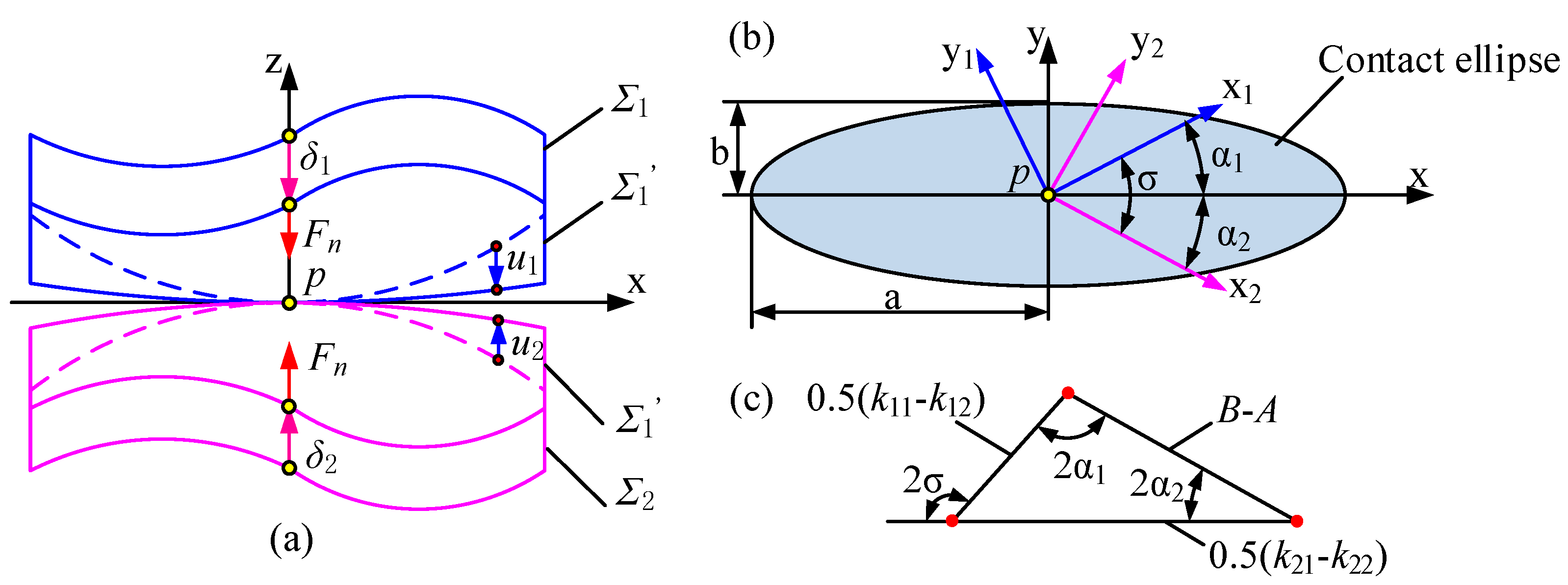
3.2.2. Contact Stress Calculation

To accurately estimate the actual tooth contact situation, it is indispensable to consider the effect of load during the meshing process. Load tooth contact analysis (LTCA) developed from TCA, and further considers the elastic deformation of the two tooth surfaces at the interact point so that the interact point expands into a contact ellipse.
Before conducting contact ellipse calculations, the contact process satisfies the following three assumptions: (1) the contact body is a linear elastic body that follows the generalized Hooke’s law; (2) The two surfaces are in smooth contact without frictional force; (3) The area of the contact surface is significantly smaller than the curvature radius of the contacting body. Consequently, the contact behavior adheres to Hertz’s theory of point contact.
According to Hertz point contact theory, due to elastic deformation, the contact point P becomes an elliptical contact area. When a normal contact force Fn is applied, the surfaces Σ1 and Σ2 deform and shift to Σ1’ and Σ2’, respectively. Points on Σ1 and Σ2 experience normal displacements u1 and u2, as shown in Figure 6. The elastic deformations at the interact point for Σ1 and Σ2 are denoted as δ1 and δ2, and their sum δ represents the total deformation.
P is the ellipse’s center. ki1 and ki2 represent the principal curvatures of the tooth surface Σi at the contact point p. May as well assume ki1 < ki2. xi and yi (i = 1,2) are the principal directions of the Σi, and the angle formed by the principal directions and the x-axis is αi. The principal curvatures and principal directions are calculated as follows.
As apparent in Figure 7, the tooth surface of the gear can be presented as r(ui, θi), and the tangent vector can be calculated by
e u = r u | r u | , e θ = r θ | r θ |
where
r u = r u , r θ = r θ
The tangent vector in any direction within the tangent plane at point P can be calculated by
t = e u sin u + e θ sin ( v u ) sin v
The value of angle u in Equation (27) is the angle formed by the tangent vector and eu, and other value v between the tangent vector eu and eθ can be obtained by following the vector equation
cos v = e u e θ ,   sin v = | e u × e θ |
The velocity vector of the contact point can be written as
v = r u d u d t + r θ d θ d t
According to Equations (27) and (29), we have
d u d t = sin u sin v v | r u | , d θ d t = sin ( v u ) sin v v | r θ |
The principal curvatures can be calculated as
k n = L d u d t 2 + 2 M d u d t d θ d t + N d θ d t 2 1 v 2
where L, M, N represent the coefficients of the second fundamental form, and they are determined by the following equations
L = r u u n ,   M = r u θ n ,   N = r θ θ n
where ruu, r and rθθ are the second derivatives of the tooth surface equation. n is the normal vector. Combining Equations (30) and (31), further expression for normal curvature can be gained as follows
k n = A sin 2 u + 2 B sin ( v u ) sin u + C sin 2 ( v u )
where
A = L r u 2 sin 2 v ,   B = M r u r θ sin 2 v ,   C = N r θ 2 sin 2 v
the principal curvature is the extremum corresponding to the normal curvature, and it can be calculated as
d k n d u = 0 tan ( 2 u ) = C sin 2 v 2 B sin v A 2 B cos v + C cos 2 v
There are two solutions for u in the Equation (35). Assuming one solution is u1, the other solution is u2 = u1 + 90°. Substituting the obtained solution into Equations (27) and (33), two corresponding principal directions and principal curvatures can be obtained.
  • According to Hertz’s elastic contact theory, when a face gear pair meshes, the contact area at the meshing point is indeed elliptical. Within the contact ellipse area, the surface pressure distribution is:
p = p 0 1 x a 2 y b 2 1 / 2
where p0 stands for the pressure at the core of the ellipse. a and b are the semi-major axis and the semi-minor axis of the contact ellipse respectively, and they can be expressed as
a = 1 E * 3 F n 2 π W 1 e 2 K e E e 1 / 3 b = a 1 e 2
where e is the eccentricity. E* represents the equivalent elastic modulus, which can be calculated using Poisson’s ratios v1 and v2, along with the elastic moduli E1 and E2 of the two gear materials.
1 E = 1 v 1 2 E 1 + 1 v 2 2 E 2
K(e) and E(e) refer to the first and second elliptic integrals, respectively. W is a positive constant, and it can be calculated as
W = A B 4 A = k 11 + k 12 + k 21 + k 22 B = k 11 k 12 2 + k 21 k 22 2 + 2 k 11 k 12 k 21 k 22 cos 2 σ
From the above, it can be obtained that the contact stress is distributed as a semi-ellipsoid in space, therefore the total load is expressed as
F n = 2 π a b p 0 3
Accordingly, the maximum contact stress can be calculated as
P 0 = 3 F n 2 π a b
It is important to note that the formula mentioned above is solely applicable for calculating contact stress in elastic half-space point contacts and is not suitable for determining contact stress on the tooth surface during edge contact situations.

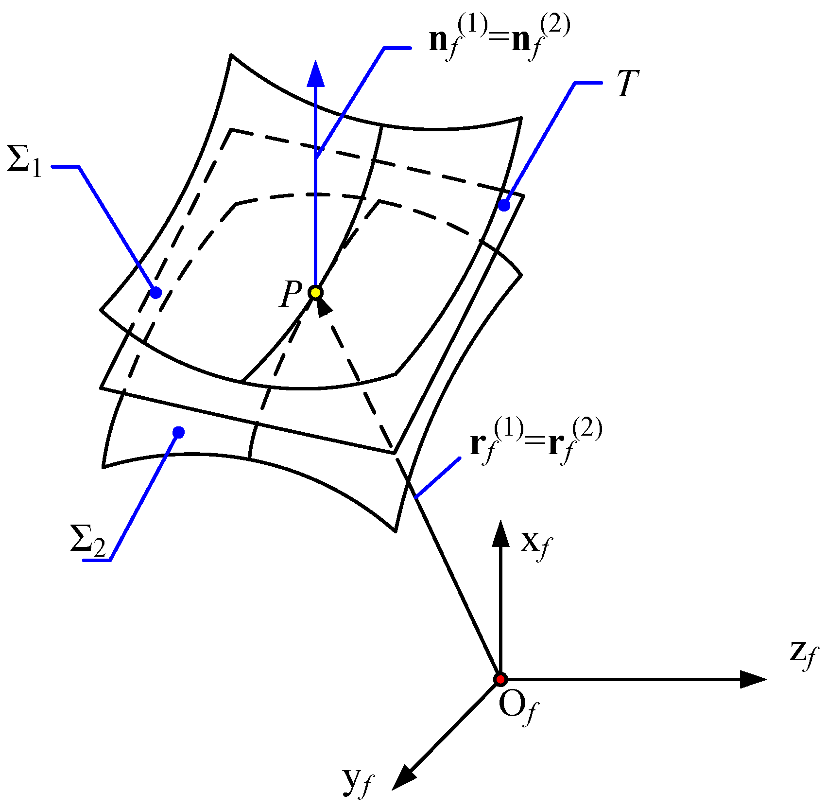
3.2.3. Edge Contact Assessment
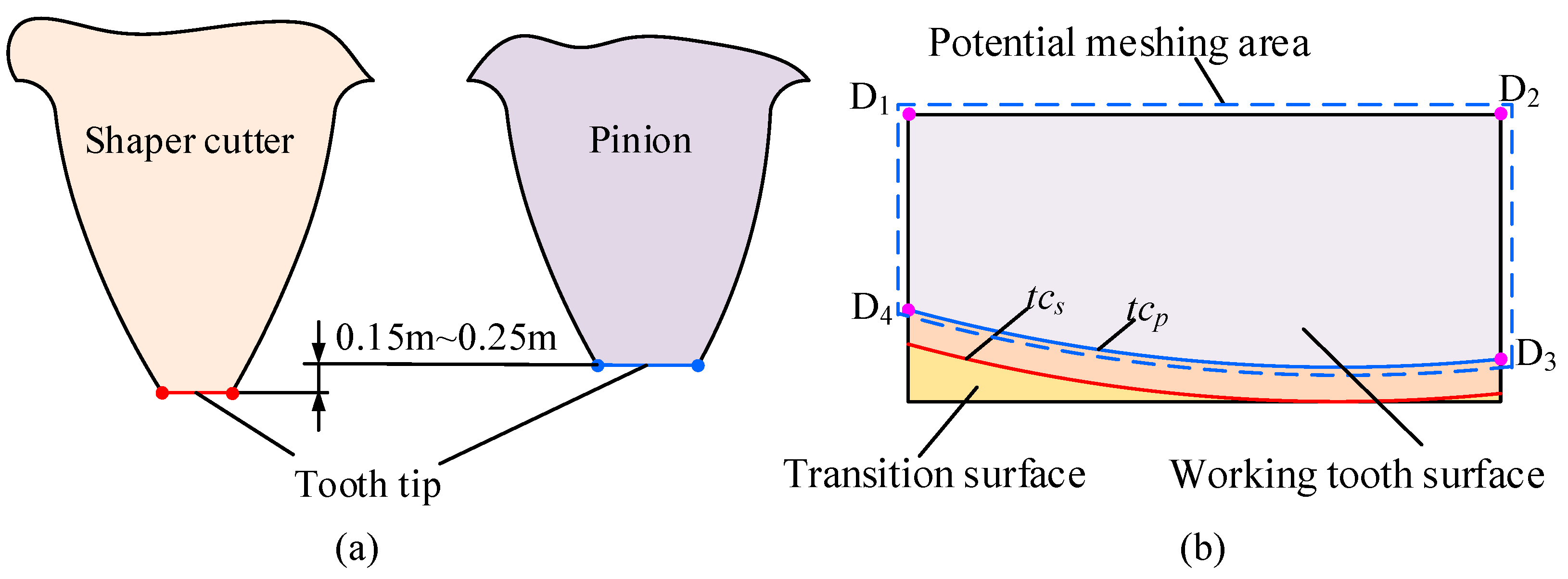
According to the LTCA results, the contact area on the tooth surface consists of several contact ellipses. At a specific moment, the contact point is first identified through TCA, and then the orientation of the contact ellipse, and dimensions of its major and minor axes, are calculated using LTCA. Given that the major axis of the ellipse is usually significantly larger than the minor axis, the edge contact within the contact region can be determined by checking whether the ends of the major axis fall within the potential meshing region of the tooth surface. This problem is then simplified to evaluating whether a given point lies within a defined area. The procedure for determining edge contact is explained in detail as follows.
(1)
Potential meshing area on the tooth surface
The potential meshing area defines the maximum boundary within which the tooth surfaces of the two gears can engage during operation. This area is typically a subset of the gears’ working tooth surfaces. The tooth surface of the face gear is categorized into two separate areas based on the manufacturing process: the working tooth surface and the transition surface. The working tooth surface with the involute profile created by the shaper cutter, whereas the transition surface is produced by the movement of the tooth tip, which represents the intersection of the tooth flank and the tooth crest surface of the shaper cutter, as apparent in Figure 8. The boundary, denoted as tcs, separates the working tooth surface from the transition surface, and its height is determined by the radius of the tooth tip circle of the shaper cutter.
In comparison to the shaper cutter, the tooth tip circle of paired cylindrical gears (pinion) is smaller, which creates clearance and ensures smooth gear operation. As a result, the boundary line tcp that separates the working tooth surface from the transition surface for cylindrical gears is positioned higher than tcs, as illustrated in Figure 8b. The region enclosed by points D1D2D3D4 represents the potential meshing area, as shown in Figure 8b.
(2)
The range of the contact ellipse
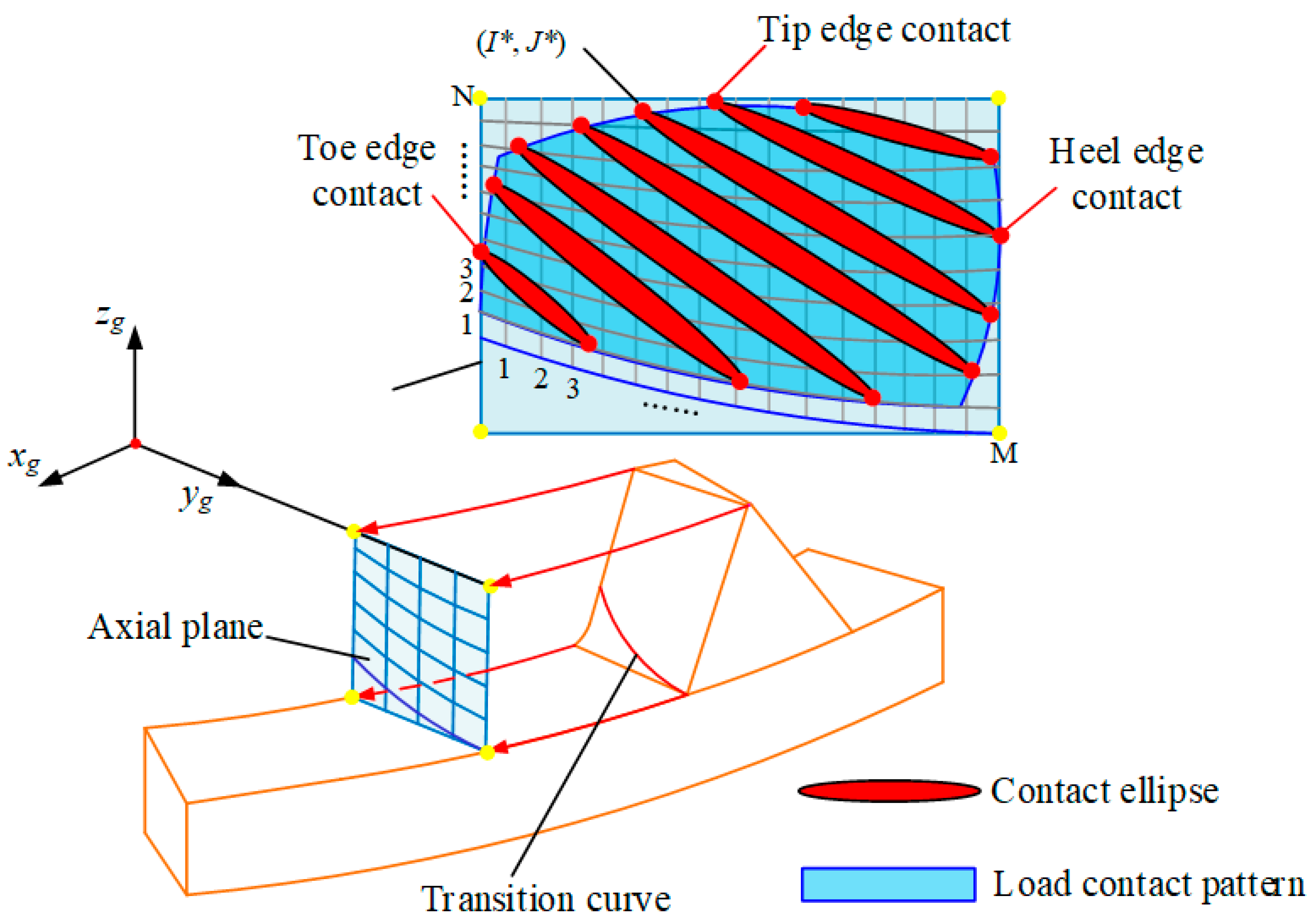
Considering that the contact ellipse typically has a significantly longer major axis compared to its minor axis, an effective way to characterize the size of the ellipse is by specifying the two terminal points of the major axis. The center of the contact ellipse is computed using Equation (23), while the length of the major axis is determined by Equation (37). The orientation of the major axis is determined by the principal directions of the tooth surface. Let the unit vector representing the direction of the major axis be denoted as
u = u x u y u z T
Thus, the positions of the endpoints of the major axis can be expressed as
P 1 = x p + a u x y p + a u y z p + a u z T P 2 = x p a u x y p a u y z p a u z T
(3)
Criterion of edge contact of face gear drives
The interaction happens in the edge of one gear tooth and the surface of another gear tooth is known as interface edge contact. Once the potential contact area and the coordinates of the major axis endpoints are identified, the occurrence of edge contact can be assessed through the following steps. (1) Define an axis plane and set up a coordinate system Sg, as illustrated in Figure 9. The origin is positioned at the tooth top plane of the face gear, with zg aligned along the rotation axis of the face gear. yg represents the radial direction of the face gear, extending from the inner diameter toward the outer diameter. (2) Rotate the potential meshing area D1D2D3D4 around the zg axis and project it onto the plane O-zgyg to obtain the projection plane D’1D’2D’3D’4 of the potential area. (3) Rotate the coordinates of the major axis endpoints of the contact ellipse, as determined by Equation (43), around the zg and project them onto the O-zgyg plane to obtain the projected coordinates of these endpoints. (4) As shown in Figure 9, the projection plane D’1D’2D’3D’4 of the potential area is divided into a regular grid. Points PIJ, where I ∈ [1, M] and J ∈ [1, N], are sampled from this grid, resulting in M × N sampling points. Under edge-contact conditions depicted in Figure 9, there necessarily exists at least a single point positioned on the boundary edge of the projection plane, meaning that either I will be either 1 or M or J will be either 1 or N. Therefore, the edge contact criterion can be expressed as follows
S 2 X = 0 1 < I * < M , 1 < J * < N 1 o t h e r s
The edge contact criterion, as given in Equation (44), is a Boolean expression with two possible outcomes: true or false.

4. Discussion and Validation

4.1. Examples Description

4.1.1. The Parameters of the Face Gear Pairs

This section aimed to validate the collaborating design method presented in this study. We employed calculation, and simulation for verification. The parameters relevant to the designing and skiving procedure for the face gear pair, employed in the verification process, are displayed in Table 1.

4.1.2. Optimization Model Settings

The parameter δ represents the amplitude of the transmission error, and this is the design parameter of the face gear pairs. According to existing experience [36], the range of the transmission error usually is 0.005~0.01° (8.7 × 10⁻⁵~1.7 × 10⁻⁴ rad). In our work, 1 × 10⁻⁵ is chosen as a case to verify the proposed collaborative design method. Hence, the predetermined range of the transmission error δ0 is set to 1 × 10⁻⁵. In the stage of the Rough dispersion, each term of X is evenly dispersed into 30 discrete points in the range XL through XU, where
X L = 0.005 5 0 10 T
X U = 0.005 5 1 e 4 10 T
In the Refined dispersion stage, the discretization density Δ0 threshold is set to 1 × 10⁻³.

4.2. Results and Discussion

4.2.1. Tooth Surface Deviation Analysis

A diagram, showing the tooth surface of the skived face gear and its deviation distribution compared to the theoretical tooth surface is shown in Figure 10.
The deviation distribution trends on both the left and right tooth surfaces show similar patterns and magnitudes, as shown in Figure 10. For a single tooth surface, the error distribution exhibits both undercutting and material residuals. The maximum residual occurs at the tooth top at the outer radius with a value of 2.1 × 10⁻² mm, followed by another significant point at the tooth root at the inner radius with a value of 2.0 × 10⁻² mm. Conversely, the maximum undercutting is observed at the tooth root at the outer radius with a value of −1.9 × 10⁻² mm, with the second significant position at the tooth top at the inner radius being −1.8 × 10⁻² mm. Undercutting mainly occurs close to the tooth root at the outer radius and the tooth top at the inner radius. In contrast, residuals are mostly found near the tooth root at the inner radius and the tooth top at the outer radius. The overall error across the tooth surface manifests in a twisted hyperbolic paraboloid distribution. Based on the face gear meshing process, interference or edge contact is probable to happen close to the tooth root at the inner radius and the tooth top at the outer radius.

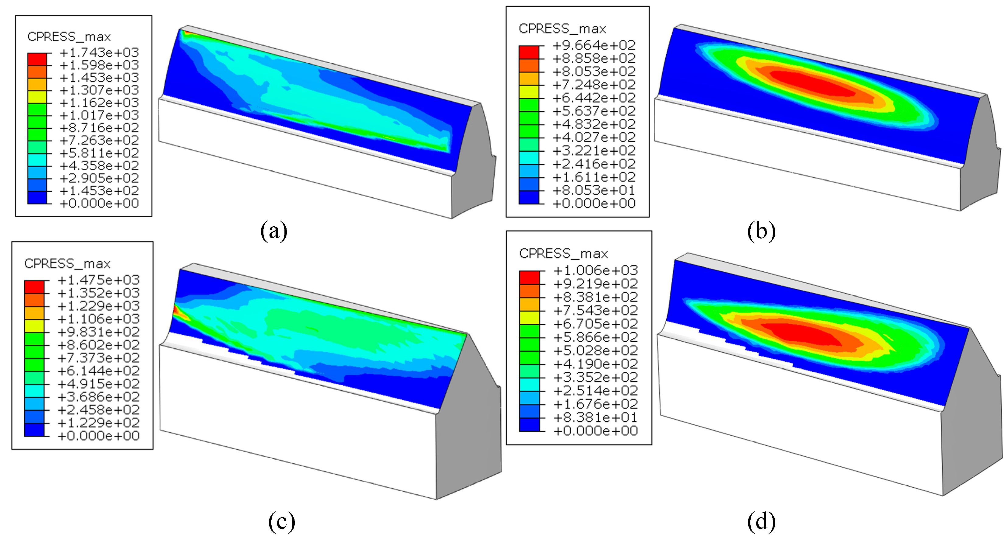
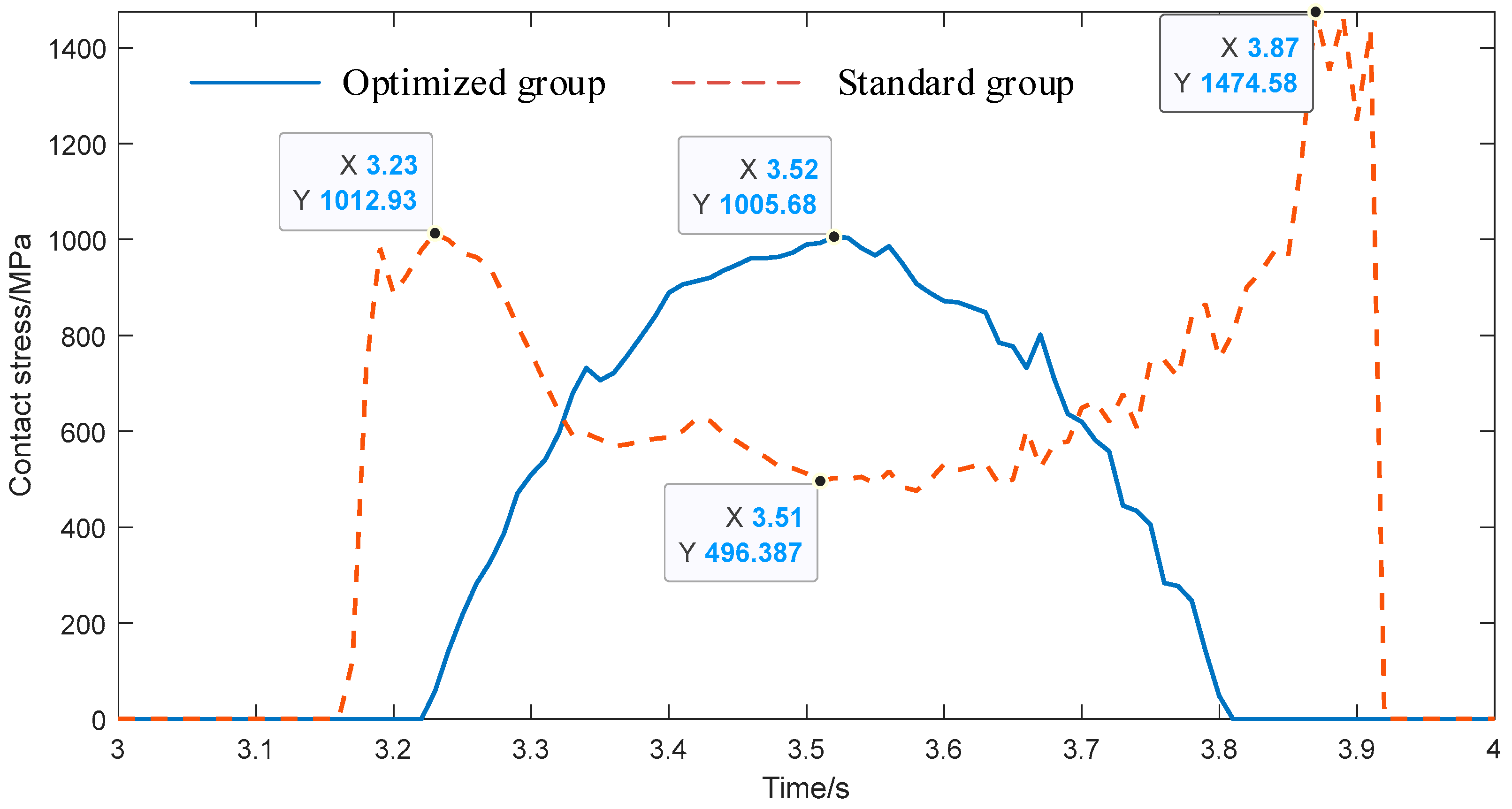
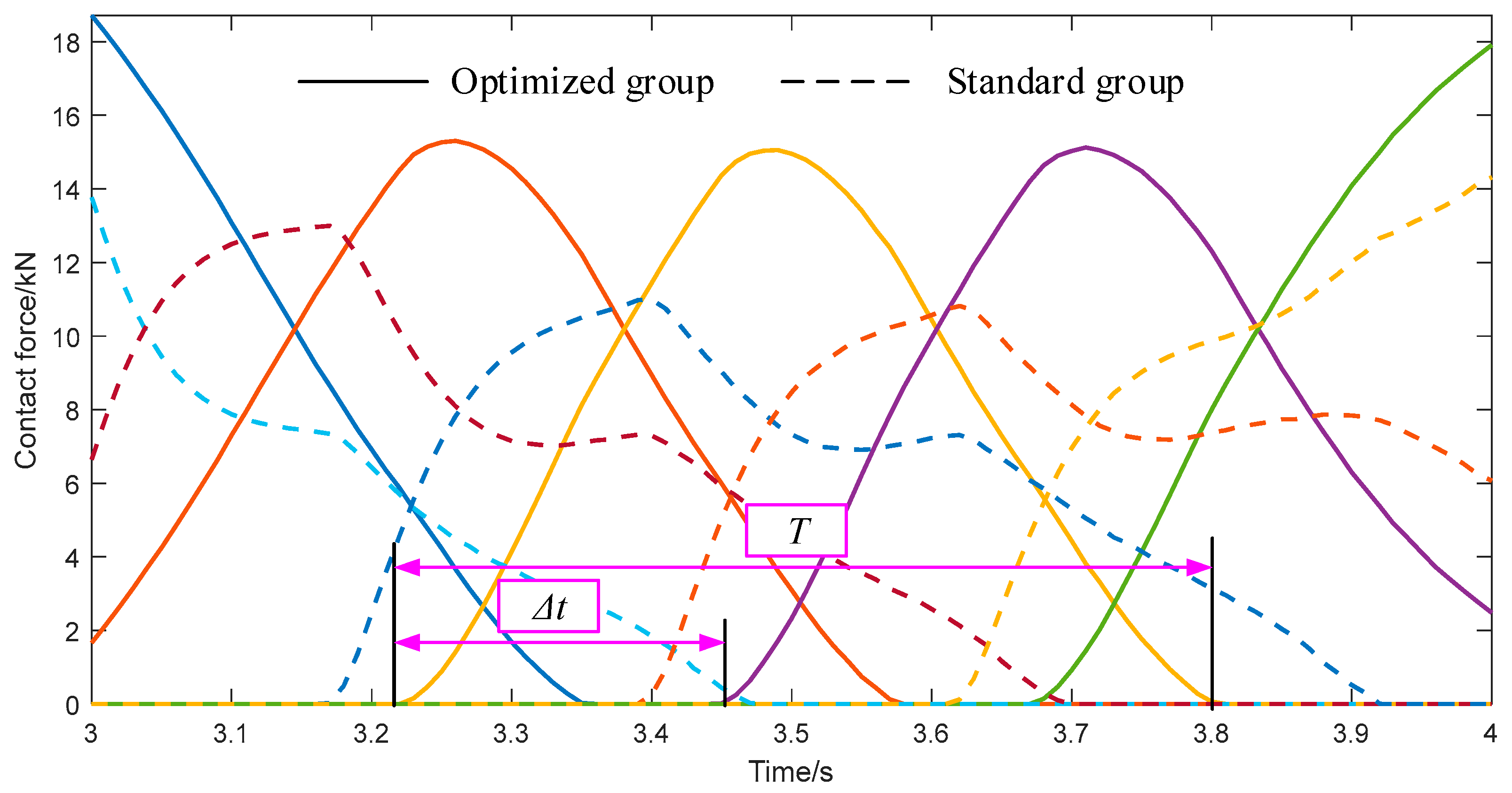
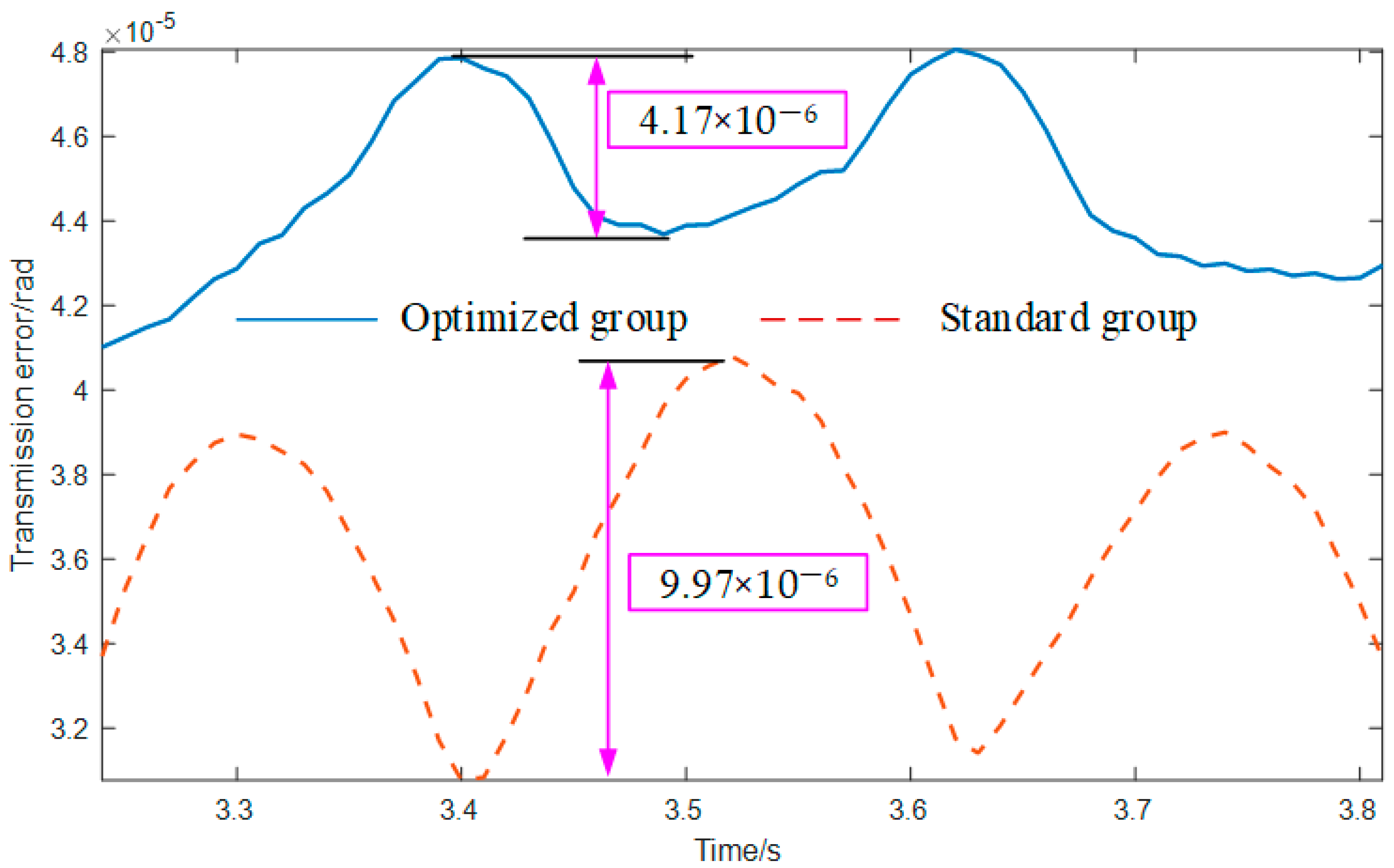
4.2.2. Contact Performance

Based on the analysis above, using a standard pinion in direct mesh with a skived face gear is likely to result in interference. Therefore, a cooperative design approach was employed to redesign the tooth surface of the pinion in our work. Utilizing the optimization model established in Section 3, the optimized parameters for the crowning of the pinion tooth surface were derived, as detailed in Figure 11.
A 3D model of the crowned pinion was then developed based on the optimization results presented in Figure 11. The finite element method was used to simulate the meshing processes of both the crowned pinion and the standard pinion with the skived face gear. The simulations provided results on contact patterns, transmission errors, and contact ratios, which were then compared. The conditions for the finite element simulations are outlined in Table 2, and the comparative results of the two approaches are illustrated in Figure 12, Figure 13, Figure 14 and Figure 15.
The contact patterns of the standard group and the optimized group are depicted in Figure 12. When a standard cylindrical gear meshes with a skived face gear, significant edge contact occurs on the tooth surface during both the biting-in and biting-out phases. The high-stress area primarily develops at the edges of the tooth surface during these phases, leading to stress concentration and accelerating gear drive failure. The stress value at the center of the tooth surface, where no edge contact occurs, is relatively lower, around 540 MPa. However, when the optimized cylindrical gear engages with the face gear, the edge contact is eliminated, and the high-stress region shifts to the center of the tooth surface, where the maximum contact stress reaches 1000 MPa.
Figure 13 shows the curve of the maximum contact stress value of the face gear tooth surface in the meshing process under these two groups of conditions. The vertical axis represents the contact stress values, while the horizontal axis represents the moments of meshing. It is important to note that the meshing moments here refer solely to the progression in the finite element analysis (FEA), and are unrelated to real-time. For the standard group, the stress increases sharply to 1012.93 MPa at the time of biting, and with the meshing process, the meshing position moves to the center of the tooth surface, when the stress gradually decreases to about 496.387 MPa. Then, the stress increases again to 1474.58 MPa, and finally, the tooth is biting out. However, the stress value of the optimized group gradually increases from the beginning of the biting in, reaching a maximum of 1005.68 MPa. At this time, the meshing position is in the center of the tooth surface, and then, with the progress of the biting out, the stress gradually decreases until 0. Compared with the standard group, there is only one peak value in the stress change process of the optimization group. Although its peak value (1005.68 MPa) is larger than that of the standard group (496.387 MPa) simultaneously, it is located in the center of the tooth surface, which can better bear large loads and avoid failure easily.
Another point worth noting is that the meshing time of a single tooth in the optimized group is shorter than that of the standard group, which is reflected in the frequency of the non-zero value of the curve in this figure. A shorter frequency indicates that the contact ratio is smaller and the meshing force on a single tooth is larger, which is a significant factor contributing to the higher tooth surface stress observed in the optimized group compared to the standard group, specifically when the stress is centered on the tooth surface.
To more accurately calculate the contact degree of gears under the two conditions, Figure 14 indicates the change curve of the contact force on each contact pair of face gears during the meshing process under the two conditions. According to the reference [37], the contact ratio of the gear pair can be expressed as
CR = T Δ t
where T is the duration of engagement of a single gear tooth, and Δt is the difference between the time of engagement of two adjacent gear teeth, its specific significance is shown in Figure 14. In this figure, different colors represent different contact pairs. According to Equation (47), it can be calculated that the contact ratios of the standard group and the optimized group are 3.41 and 2.45, respectively, which indicates that the load on a single tooth in the optimized group is greater. The decrease in contact ratio is a negative consequence brought about by avoiding edge contact. In this paper, to avoid edge contact, the tooth surface of the cylindrical gear is modified by adjusting its tooth surface modification parameters, resulting in a convex shape. This modification helps prevent edge contact during the meshing and de-meshing moments. As a result, the time for a single-gear tooth to participate in meshing becomes shorter, leading to an increase in the load on a single gear tooth. This, to some extent, causes an increase in the contact stress on the tooth surface. However, considering that edge contact can bring a higher risk of gear failure, it is essential to find a reasonable balance between avoiding edge contact and controlling the tooth surface contact stress.
Another important meshing performance evaluation index is the size of the transfer error, and its calculation formula can be found in the reference [37], which will not be repeated here. The amplitude and shape of the transmission error represent the stationarity in the transmission process. Figure 15 shows the transmission error curve for both groups. It indicates from the figure that the transmission error curves of both the standard and optimized groups are smooth. Compared with the standard, the optimized group has a smoother transmission error curve and a smaller transmission error amplitude, so its transmission process will be more stable.
In summary, compared with the standard cylindrical gear, the optimized group by the method proposed in this paper can better avoid edge contact when meshing with the skived face gear, and the tooth surface has lower contact stress and transmission error amplitude, but this leads to a decrease in the contact ratio and an increase in contact stress at the center of the tooth surface. However, as long as the contact stress is controlled within the acceptable scope of the material properties, the reliability of the transmission process can be improved by better controlling the position of the high-stress region.

5. Conclusions

This work proposed a collaborating design method for the pinion of the skived face gear driven by the contact performance, and the main contributions and findings are summarized as follows.
(a)
The mathematical model of the tooth surface of the cylindrical gear is established where the tooth surface modifications are applied in both profile and longitudinal directions.
(b)
Based on the two-parameter enveloping process, the mathematical model of the tooth surface of the skived face gear was established, and the trend and characteristics of the tooth surface error distribution were analyzed by comparing it with the standard face gear tooth surface;
(c)
Based on the analytical method, the method of evaluating the tooth surface edge contact is given, and the optimization model driven by the meshing performance is established.
(d)
The effectiveness of the optimization model and method proposed in this paper is verified by example simulations. Compared with the standard cylindrical gear, the optimized tooth surface has better meshing performance. Compared with the standard cylindrical gear, the optimized group by the method proposed in this paper can better avoid edge contact when meshing with the skived face gear, and the tooth surface has lower contact stress (standard group: 1474.58 MPa, optimized group: 1005.68 MPa) and transmission error amplitude (standard group: 9.97 × 10⁻⁶ rad, optimized group: 4.17 × 10⁻⁶ rad), but the contact ratio is decreased and the contact stress at the center of the tooth surface is increased.
(e)
With the proposed method in this paper, redesigning the tooth surface of the cylindrical gear without the need for repeated revisions to the tooth surface of the face gear. The well-established cylindrical gear manufacturing technology offers a flexible option for the practical application of this method.

Author Contributions

Methodology, Z.Z.; Software, M.L.; Validation, J.T.; Formal analysis, M.L.; Investigation, Z.Z.; Resources, Y.Z. (Yuanyuan Zhang); Writing—original draft, Z.Z. and Z.T.; Writing—review & editing, Z.Z. and Z.T.; Visualization, Y.Z. (Yuanyuan Zhang); Supervision, Y.Z. (Yuansheng Zhou) and J.T.; Project administration, Y.Z. (Yuansheng Zhou); Funding acquisition, Y.Z. (Yuansheng Zhou), J.T. and L.Z. All authors have read and agreed to the published version of the manuscript.

Funding

This research was funded by the Industry University Research Cooperation Project of China Aviation Engine Group Co, Ltd., Grant number HFZL2024CXY020, National Natural Science Foundation of China, Grant number 52075558, by Science and Technology Innovation Program of Hunan Province, Grant number 2021RC3012, by Central South University Innovation-Driven Research Program, Grant number 2023CXQD050, by the Fundamental Research Funds for the Central Universities of Central South University, Grant number CX20230255, by AECC, Grant Number KY-1044-2023-0461.

Data Availability Statement

The original contributions presented in this study are included in the article. Further inquiries can be directed to the corresponding author.

Acknowledgments

The authors gratefully acknowledge the financial support of the Industry University Research Cooperation Project of China Aviation Engine Group Co, Ltd. (HFZL2024CXY020), the National Natural Science Foundation of China (52075558), the Science and Technology Innovation Program of Hunan Province (No. 2021RC3012), Central South University Innovation-Driven Research Program (2023CXQD050), the Fundamental Research Funds for the Central Universities of Central South University (CX20230255), and AECC (KY-1044-2023-0461).

Conflicts of Interest

Author Yuanyuan Zhang was employed by the company AECC Zhongchuan Transmission Machinery Co., Ltd., Author Liang Zhou was employed by the company State Grid Loudi Power Supply Company. The remaining authors declare that the research was conducted in the absence of any commercial or financial relationships that could be construed as a potential conflict of interest.

References

  1. Chen, X.-C.; Li, J.; Lou, B.-C. A study on the design of error-free spur slice cutter. Int. J. Adv. Manuf. Technol. 2013, 68, 727–738. [Google Scholar] [CrossRef]
  2. Chen, X.; Li, J.; Lou, B.; Shi, J.; Yang, Q. Effect of the cutter parameters and machining parameters on the interference in gear slicing. Chin. J. Mech. Eng. 2013, 26, 1118–1126. [Google Scholar] [CrossRef]
  3. Guo, E.; Hong, R.; Huang, X.; Fang, C. A correction method for power skiving of cylindrical gears lead modification. J. Mech. Sci. Technol. 2015, 29, 4379–4386. [Google Scholar] [CrossRef]
  4. Guo, E.; Hong, R.; Huang, X.; Fang, C. A novel power skiving method using the common shaper cutter. Int. J. Adv. Manuf. Technol. 2016, 83, 157–165. [Google Scholar] [CrossRef]
  5. Guo, Z.; Mao, S.-M.; Li, X.-E.; Ren, Z.-Y. Research on the theoretical tooth profile errors of gears machined by skiving. Mech. Mach. Theory 2016, 97, 1–11. [Google Scholar] [CrossRef]
  6. Tsai, C.-Y. Mathematical model for design and analysis of power skiving tool for involute gear cutting. Mech. Mach. Theory 2016, 101, 195–208. [Google Scholar] [CrossRef]
  7. Tsai, C.-Y. Integrated mathematical approach for design and manufacturing of power-skiving tool for interference-free involute internal gear cutting. Mech. Mach. Theory 2023, 180, 105172. [Google Scholar] [CrossRef]
  8. Tsai, C.-Y. Simple mathematical approach for analyzing gear tooth profile errors of different gears cut using same power-skiving tool. Mech. Mach. Theory 2022, 177, 105042. [Google Scholar] [CrossRef]
  9. Moriwaki, I.; Osafune, T.; Nakamura, M.; Funamoto, M.; Uriu, K.; Murakami, T.; Nagata, E.; Kurita, N.; Tachikawa, T.; Kobayashi, Y. Cutting Tool Parameters of Cylindrical Skiving Cutter with Sharpening Angle for Internal Gears. J. Mech. Des. 2017, 139, 033301. [Google Scholar] [CrossRef]
  10. Shih, Y.-P.; Li, Y.-J. A Novel Method for Producing a Conical Skiving Tool with Error-Free Flank Faces for Internal Gear Manufacture. J. Mech. Des. 2018, 140, 043302. [Google Scholar] [CrossRef]
  11. Bergs, T.; Georgoussis, A.; Löpenhaus, C. Development of a numerical simulation method for gear skiving. Procedia CIRP 2020, 88, 352–357. [Google Scholar] [CrossRef]
  12. Wang, P.; Han, L.; Li, J.; Liu, F. Research on design and manufacturing of gear slicing cutter for circular arc tooth. Int. J. Adv. Manuf. Technol. 2021, 113, 2017–2029. [Google Scholar] [CrossRef]
  13. Hoang, M.-T.; Tran, T.-V.; Tran, V.-Q. Rack Modification Method for Skiving Cutter Considering Grinding Allowance of Work Gear. In International Conference on Advanced Mechanical Engineering, Automation and Sustainable Development; Long, B.T., Kim, H.S., Ishizaki, K., Toan, N.D., Parinov, I.A., Kim, Y.-H., Eds.; Springer International Publishing: Cham, Switzerland, 2022; pp. 105–110. [Google Scholar] [CrossRef]
  14. Luu, T.-T.; Wu, Y.-R. A novel correction method to attain even grinding allowance in CNC gear skiving process. Mech. Mach. Theory 2022, 171, 104771. [Google Scholar] [CrossRef]
  15. Luu, T.-T.; Wu, Y.-R. A novel approach to attain tooth flanks with variable pressure and helical angles utilizing the same cutter in the CNC gear skiving process. Int. J. Adv. Manuf. Technol. 2022, 123, 875–902. [Google Scholar] [CrossRef]
  16. Han, Z.; Chuang, J.; Deng, X. Research on the profile modification of power skiving tool for internal gears. Int. J. Adv. Manuf. Technol. 2022, 121, 3463–3475. [Google Scholar] [CrossRef]
  17. Guo, E.; Hu, L.; Zhang, E.; Liu, C.; Xu, J.; He, W. A cylindrical skiving tool design method based on a conjugate surface for internal gear manufacture. J. Manuf. Process. 2023, 101, 1538–1550. [Google Scholar] [CrossRef]
  18. Olivoni, E.; Vertechy, R.; Parenti-Castelli, V. On the profile change of conical skiving tools after re-sharpening. Procedia CIRP 2024, 126, 1053–1058. [Google Scholar] [CrossRef]
  19. Ding, S.; Song, Z.; Wu, W.; Guo, E.; Huang, X.; Song, A. Geometric error modeling and compensation of horizontal CNC turning center for TI worm turning. Int. J. Mech. Sci. 2020, 167, 105266. [Google Scholar] [CrossRef]
  20. Ren, Z.; Fang, Z.; Kobayashi, G.; Kizaki, T.; Sugita, N.; Nishikawa, T.; Kugo, J.; Nabata, E. Influence of tool eccentricity on surface roughness in gear skiving. Precis. Eng. 2020, 63, 170–176. [Google Scholar] [CrossRef]
  21. Ren, Z.; Fang, Z.; Arakane, T.; Kizaki, T.; Nishikawa, T.; Feng, Y.; Kugo, J.; Nabata, E.; Sugita, N. Parametric modeling of uncut chip geometry for predicting crater wear in gear skiving. J. Mater. Process. Technol. 2021, 290, 116973. [Google Scholar] [CrossRef]
  22. Han, Z.; Jiang, C.; Deng, X. Machining and meshing analysis of face gears by power skiving. J. Adv. Mech. Des. Syst. Manuf. 2022, 16, JAMDSM0002. [Google Scholar] [CrossRef]
  23. Zhengyang, H.; Chuang, J.; Xiaozhong, D. Research on machining nonorthogonal face gears by power skiving with tooth flank modification based on a six-axis machine tool. Int. J. Adv. Manuf. Technol. 2022, 121, 2735–2746. [Google Scholar] [CrossRef]
  24. Tsai, C.-Y. Power-skiving tool design method for interference-free involute internal gear cutting. Mech. Mach. Theory 2021, 164, 104396. [Google Scholar] [CrossRef]
  25. Shih, Y.-P.; Li, Y.-J.; Lin, Y.-C.; Tsao, H.-Y. A novel cylindrical skiving tool with error-free flank faces for internal circular splines. Mech. Mach. Theory 2022, 170, 104662. [Google Scholar] [CrossRef]
  26. Janßen, C.; Tsakiris, S.; Solf, M.; Bergs, T. Investigation of the manufacturability of topological modifications using adapted kinematics for gear skiving. Procedia CIRP 2024, 126, 537–542. [Google Scholar] [CrossRef]
  27. Xu, M.; Han, X.; Zheng, F.; Hua, L.; Zeng, Y. Design and Manufacture Method of Aviation Face Gear with High Load-Bearing Based on Gear Skiving Process. J. Manuf. Sci. Eng. 2024, 146, 031009. [Google Scholar] [CrossRef]
  28. Wang, P.; Liu, F.; Li, J. Analysis and optimization of gear skiving parameters regarding interference and theoretical machining deviation based on chaos map. Int. J. Adv. Manuf. Technol. 2021, 112, 2161–2175. [Google Scholar] [CrossRef]
  29. Wang, P.; Li, J.; Han, L. Research on the Cutting Principle and Tool Design of Gear Skiving Based on the Theory of Conjugate Surface. Math. Probl. Eng. 2021, 2021, 5469020. [Google Scholar] [CrossRef]
  30. Guo, H.; Ma, T.; Zhang, S.; Zhao, N.; Fuentes-Aznar, A. Computerized generation and surface deviation correction of face gear drives generated by skiving. Mech. Mach. Theory 2022, 173, 104839. [Google Scholar] [CrossRef]
  31. Lin, X.; Liu, Y.; Sun, S.; Jin, G.; Hong, R. Prediction and optimization of gear skiving parameters and geometric deviations. Int. J. Adv. Manuf. Technol. 2022, 121, 4169–4185. [Google Scholar] [CrossRef]
  32. Hrytsay, I.; Slipchuk, A.; Bosansky, M. Justification of the Choice of Parameters for the Gear Power Skiving Operation Based on Computer Simulation. Stroj. Časopis—J. Mech. Eng. 2023, 73, 33–44. [Google Scholar] [CrossRef]
  33. Wang, Z.; Tang, Z.; Zhou, Y.; Zeng, B.; Tang, J. A comprehensive optimization method for considering the theoretical and practical machining errors to the accurate power skiving of spur face gears by optimizing both cutting edges and tool path. J. Comput. Des. Eng. 2024, 11, 184–202. [Google Scholar] [CrossRef]
  34. Le, K.-Q.; Wu, Y.-R.; Tran, V.-Q.; Tran, H.-Q. A flexible method to correct tooth surface deviation for CNC power skiving of face gears. Int. J. Adv. Manuf. Technol. 2024, 134, 3665–3685. [Google Scholar] [CrossRef]
  35. Le, K.-Q.; Wu, Y.-R.; Luu, T.-T. A Mathematical Modeling of Computer Numerical Control Skiving Process for Manufacturing Helical Face Gears Using Sensitivity Matrix Combined with Levenberg-Marquardt Algorithm. J. Manuf. Sci. Eng. 2024, 146, 091007. [Google Scholar] [CrossRef]
  36. Inoue, T.; Kurokawa, S. Meshing mechanism considering various combinations of assembly and manufacturing errors on face gear using a transmission-error-controlled curve. J. Adv. Mech. Des. Syst. Manuf. 2023, 17, JAMDSM0068. [Google Scholar] [CrossRef]
  37. Litvin, F.L.; Fuentes, A. Gear Geometry and Applied Theory; Cambridge University Press: Cambridge, UK, 2004. [Google Scholar]
Figure 1. Tooth profile and tooth direction modification diagram of spur cylindrical gear.
Mathematics 13 01180 g001
Figure 2. Kinematics of the face gear skiving.
Mathematics 13 01180 g002
Figure 3. Coordinate systems of face gear power skiving.
Mathematics 13 01180 g003
Figure 4. 3D model of the skiving cutter.
Mathematics 13 01180 g004
Figure 5. Tangential contact between two tooth surfaces in gear transmission.
Mathematics 13 01180 g005
Figure 6. The elastic deformation of the contact point on the tooth surface: (a) deformation diagram; (b) contact ellipse; (c) curvature relationship.
Mathematics 13 01180 g006
Figure 7. The tooth surface and the tangent vectors.
Mathematics 13 01180 g007
Figure 8. The potential meshing area on the tooth surface of face gears: (a) the profile of the shaper cutter and the pinion; (b) the tooth surface of the face gear.
Mathematics 13 01180 g008
Figure 9. Tooth surface discretization and loaded contact pattern evaluation.
Mathematics 13 01180 g009
Figure 10. The tooth surface of the skived face gear and its deviation distribution.
Mathematics 13 01180 g010
Figure 11. The crowning tooth surface of the optimized pinion.
Mathematics 13 01180 g011
Figure 12. The contact patterns of the standard group and the optimized group: (a) the pinion of the standard group; (b) the pinion of the optimized group; (c) the face gear of the standard group; (d) the face gear of the optimized group.
Mathematics 13 01180 g012
Figure 13. The maximum contact stress on the tooth surface of the face gear during meshing processes.
Mathematics 13 01180 g013
Figure 14. The contact force of the standard and optimized groups in meshing processes (different colors represent different contact pairs).
Mathematics 13 01180 g014
Figure 15. The transmission errors of the standard group and the optimized group.
Mathematics 13 01180 g015
Table 1. The parameters of the face gear pair.
ItemsSignValue
(1) Parameters of the face gear pair
Modulem3.95 mm
Pressure angleα25°
The teeth number of the face gearNf140
The teeth number of the pinionNp34
The teeth number of the shaper cutterNs35
The outer semi-diameter of the face gearRmax260 mm
The inner semi-diameter of the face gearRmin305 mm
Tooth width of the pinionB50 mm
(2) Parameters of the skiving cutter
Normal modulemc3.95 mm
Normal pressure angleαc25°
Teeth numberNc23
Helix angleβc10° (RH)
Rake angleγ
Relief angleαe
Table 2. The conditions for the finite element simulations.
Material PropertiesWork Condition
Young’s modulusPoisson’s ratioDriven wheel load
210 GPa0.29512 N·m
Disclaimer/Publisher’s Note: The statements, opinions and data contained in all publications are solely those of the individual author(s) and contributor(s) and not of MDPI and/or the editor(s). MDPI and/or the editor(s) disclaim responsibility for any injury to people or property resulting from any ideas, methods, instructions or products referred to in the content.

