Article

A Simple-FSDT-Based Isogeometric Method for Piezoelectric Functionally Graded Plates

1
Department of Mechatronic Engineering and Automation, Shanghai University, Shanghai 200072, China
2
Department of Mechanical Engineering, Anhui University of Technology, Ma’anshan 243002, China
3
Science, Mathematics and Technology Cluster, Singapore University of Technology and Design (SUTD), 8 Somapah Road, Singapore 487372, Singapore
4
SUTD-Massachusetts Institute of Technology International Design Centre, Singapore 487372, Singapore
*
Authors to whom correspondence should be addressed.
Mathematics 2020, 8(12), 2177; https://doi.org/10.3390/math8122177
Submission received: 16 November 2020 / Revised: 1 December 2020 / Accepted: 4 December 2020 / Published: 6 December 2020
(This article belongs to the Special Issue Applied Mathematics and Solid Mechanics)

Abstract

:
An efficient isogeometric analysis method (IGA) based on a simple first-order shear deformation theory is presented to study free vibration, static bending response, dynamic response, and active control of functionally graded plates (FGPs) integrated with piezoelectric layers. Based on the neutral surface, isogeometric finite element motion equations of piezoelectric functionally graded plates (PFGPs) are derived using the linear piezoelectric constitutive equation and Hamilton’s principle. The convergence and accuracy of the method for PFGPs with various mechanical and electrical boundary conditions have been investigated via free vibration analysis. In the dynamic analysis, both time-varying mechanical and electrical loads are involved. A closed-loop control method, including displacement feedback control and velocity feedback control, is applied to the static bending control and the dynamic vibration control analysis. The numerical results obtained are accurate and reliable through comparisons with various numerical and analytical examples.

1. Introduction

Functionally graded materials (FGMs) [1] have been used extensively in the aerospace, nuclear power industries, biomedical field, and other applications [2,3,4] for their superior thermo-mechanical properties, such as low thermal conductivity and high thermal resistance. Classified as smart materials, piezoelectric materials are also known for their piezoelectric effects [5] (used as sensors) and converse piezoelectric effects (used as actuators). Unique electro-mechanical coupling characteristics of piezoelectric materials enable them to be applied in the fields of health monitoring and structural control. Accordingly, by fabricating (or embedding) piezoelectric materials on the surface (inside) of functionally graded beams, plates, shells, and other structures, they can respond rapidly according to their physical characteristics and shape changes, when the external environment changes.
Piezoelectric functionally graded plates (PFGPs) are one of the basic structural forms of piezoelectric functionally graded structures. Traditional numerical methods of PFGPs consume a mass of computational meshes based on the conventional three-dimensional elastic theory framework. To overcome these shortcomings, scholars combined various numerical methods with equivalent single layer theory [6] for predicting the behaviors of PFGPs [7,8]. The finite element method (FEM) has always been one of the popular methods to study PFGPs. Ray et al. [9] and Loja et al. [10] presented investigation for the static response analysis of PFGPs. He et al. [11] employed the piezoelectric materials to investigate the dynamic vibration control of functionally graded plates (FGPs) by using the classical plate theory (CPT). Similarly, Liew et al. [12,13] studied the active control of FGPs with distributed piezoelectric materials under thermal loads based on the first-order shear deformation theory (FSDT). Aryana et al. [14] proposed a method to identify the most sensitive design variables that affect the dynamic characteristics of the structure. Using a cell-based smoothed discrete shear gap method, Nguyen-Quang et al. [15] studied the static and dynamic control analysis of FGPs bonded with piezoelectric actuators and sensors. In this method, each parent triangle element is divided into three sub-triangle elements, and the discrete shear gap method is used in each sub-triangle element to eliminate the shear-locking effects [16]. Then, the strain smoothing technology is applied in the whole parent triangle element to solve the defect of rigidity of triangle elements in FEM. By using the higher-order shear deformation theory (HSDT), Fakhari et al. [17,18] analyzed the nonlinear free and forced vibration, as well as nonlinear vibration control of PFGPs in thermal environments. Recently, a generalized C0-type HSDT polygonal finite element method was presented by Nguyen et al. [19] for investigating the active control of smart, functionally graded metal foam plates reinforced by graphene platelets. To avoid the decrease in the calculation accuracy [20,21] caused by element distortion in the FEM, various scholars also attempted to use the mesh-free method to analyze the behaviors of PFGPs. Using the element-free Galerkin method, Dai et al. [22] investigated the static, active control analysis of FGPs with surface-bonded piezoelectric materials in thermal environments. The stability of PFGPs subjected to distributed thermo-electro-mechanical loads was studied by Chen et al. [23]. The radial point interpolation method was implemented to investigate the geometrically nonlinear response of PFGPs under mechanical and electrical loads by Hossein et al. [24]. Considering the stability of the plate in vibration control, Selim et al. [25] studied the active control of two types of PFGP structures. They pointed out that for the structure of two piezoelectric layers distributed symmetrically on the upper and lower surfaces of the FGPs, due to the stretching–bending coupling effect, the velocity feedback control in the active vibration control is unstable when the gradient index is in the range of 0 < n < ∞.
Although the FEM and mesh-free methods have achieved considerable success in the analysis of piezoelectric smart structures, there continues to be strong interest in new numerical methods. Recently, an isogeometric analysis (IGA) method was proposed by Hughes et al. [26]. Because of the advantages of high-order continuity and simple meshing, Phung-Van et al. [27] employed IGA to study the nonlinear dynamic response analysis of PFGPs under thermo-electro-mechanical loads. Similar studies of smart piezoelectric composite plates were developed by the same authors in the literature [28,29]. Along the same line, Nguyen et al. [30] and Nguyen-Quang et al. [31] presented developments of isogeometric analysis of piezoelectric, functionally graded porous plates reinforced by graphene platelets, and laminated carbon nanotube-reinforced composite plates bonded with piezoelectric materials, respectively.
The above studies on the dynamic analysis of piezoelectric smart structures are focused on the dynamic response of structures under mechanical loads. Few people pay attention to the dynamic response of the structures under time-varying voltage loads. However, many piezoelectric smart structures, such as piezoelectric motors [32] and robots [33], realize their motions precisely by utilizing the dynamic response under voltage loads. In addition, for the PFGPs, the presence of additional electric potential fields will result in more complicated mathematical modelling. Hence, a low-cost, efficient numerical method without loss of accuracy is extremely important. Most current approaches used CPT, FSDT, and HSDTs for the analysis of PFGPs. In these plate theories, CPT has the least amount of calculation because it has only three unknowns, but it is only valid for the thin plates due to the shear deformation effects being ignored [34]. The computational cost of FSDTs and HSDTs is more expensive than CPT because they have five or more unknowns. It is worth noting that Thai et al. [35,36] proposed a new simple first-order shear deformation theory (S-FSDT) with only four unknowns. Compared with FSDTs and HSDTs, the decrease of unknowns makes S-FSDT have a certain advantage in computational efficiency. Moreover, because S-FSDT is derived from FSDT, it is suitable for both thin and thick plates. The accuracy and validity of this theory for analyzing the static bending, buckling, free vibration [37], and geometrically nonlinear responses [38] of FGPs have been demonstrated.
In summary, the main motivations of this paper are: (i) there are no studies on isogeometric analysis for the analysis of PFGPs based on the simple first-order shear deformation theory, and the present study can fill this research gap; (ii) the S-FSDT-based IGA method has only four unknowns, and it is easily applied to the open-source IGA frameworks; (iii) the investigation of dynamic response of the structures under time-varying voltage loads can provide a more comprehensive understanding of the mechanical behavior of piezoelectric smart structures.
Therefore, in this paper, we propose an approach based on S-FSDT and the NURBS-based isogeometric analysis for analyzing the mechanical behavior of the PFGPs. The mechanical displacement field and electric potential field in PFGPs are approximated using the NURBS basis functions. Isogeometric finite element equations of PFGPs are derived through the linear piezoelectric constitutive equation and Hamilton’s variational principle. The dynamic response of PFGPs under mechanical loads and voltage loads are studied by using the Newmark-β direct integration method. Additionally, the static and dynamic closed-loop control are used for controlling the shapes and vibration of the plates.

2. Mathematical Model

The piezoelectric functionally graded plate is shown in Figure 1 with the size of a × b × h t (length × width × thicknesses), in which h t = h f + 2 h p , where h f and h p are the thicknesses of the FGM layer and each piezoelectric layer. The polarization directions of the upper and lower piezoelectric layers are downward and upward, respectively.

2.1. Functionally Graded Materials

The material properties of functionally graded plates along the thickness direction can be described as
P ( z ) = ( P m P c ) V m ( z ) + P c .
The volume fraction of metal materials is defined as
V m ( z ) = ( 1 2 + z h f ) n ,
where the subscript symbols m and c represent the metal and ceramic, respectively; P c and P m are the corresponding material properties, such as mass density ( ρ ), Young’s modulus ( E ), and various other properties; n is the gradient index. Figure 2 shows the variation of the composition of the FGP with n . It is seen that as n increases, the less metal components in the plate.

2.2. Mechanical Displacement and Strain Based on S-FSDT

For the simple first-order shear deformation theory, the unknowns are reduced from five to four using two assumptions [36]: first, the transverse displacement w 0 ( x , y ) in the standard FSDT is split into bending and shear parts, that is, w 0 = w b + w s ; second, the rotations β x and β y are expressed using the partial derivatives of the transverse bending components, that is, β x = w b / x and β x = w b / y .
The neutral surface is introduced to avoid the stretching–bending coupling effect. Hence, the displacement formulation of the S-FSDT can be written as
u ( x , y , z ) = u ¯ ( x , y ) + ( z z 0 ) u ( x , y ) ,
where u = { u    v    w } T , u ¯ = { u 0    v 0    w b + w s } T , and   u = { w b / x    w b / y    0 } T . In which, u 0 and v 0 represent the displacements of the neutral plane of the plate in x and y directions, respectively; β x and β y are the rotation variables; z 0 is the distance between the mid and neutral surface, which can be denoted as
z 0 = h t / 2 h t / 2 z E ( z ) d z h t / 2 h t / 2 E ( z ) d z .
The geometric strains ε ˜ can be given as
ε ˜ = { ε γ } ,
where
ε = {   ε x ε y γ x y } T = ε 0 ( z z 0 ) κ ,
γ = { γ x z γ y z } T = { w s x w s y } T ,
with
ε 0 = { u 0 , x v 0 , y u 0 , y + v 0 , x } T ,
κ = { 2 w b / x 2    2 w b / y 2    2 2 w b / x y } T .

2.3. Constitutive Relationship

For the functionally graded plates, the constitutive relationship between the geometric stresses and strains can be denoted as
σ f = Q f ε ˜ ,
where
Q f = [ Q 0 0 G ] ,
with
Q = [ Q 11 Q 12 0 Q 21 Q 22 0 0 0 Q 66 ] ,   G = [ Q 44 0 0 Q 55 ] ,
in which
Q 11 = Q 22 = E ( z ) 1 v ( z ) 2 ,   Q 12 = Q 21 = v ( z ) E ( z ) 1 v ( z ) 2 ,   Q 44 = Q 55 = E ( z ) 2 ( 1 + v ( z ) ) .
For the piezoelectric layers, the linear piezoelectric constitutive equation [18] is given by:
[ σ p D ] = [ Q p e T e g ]   [ ε ˜ E ] ,
where σ p is the stress; D is the electrical displacement; g is the permittivity constant matrix; and e is the piezoelectric stress constant matrix. Q p is the elastic constant of piezoelectric materials with the similar form of Q f .
Only the electric field component in the z direction is considered. Hence, the electric field E is calculated by
E = grad φ = { 0 0 E z } T .
The stress resultants in the PFGPs are expressed as
{ N M P } = c { ε 0 κ γ } { N P M P 0 } ,
where
c   = [ D m b 0 0 C s ] ,
with
D m b = [ A B B D ] ,   C s = k h t / 2 h t / 2 G i j d z    i , j = 4 , 5 ,
where k is the shear correction factor and it is set to be 5/6, and
A i j = h t / 2 h t / 2 Q i j d z ,    i , j = 1 , 2 , 6 ,
D i j = h t / 2 h t / 2 ( z z 0 ) 2 Q i j d z ,    i , j = 1 , 2 , 6 ,
since the introduction of neutral surface [39], B i j = 0 .
The forces and bending moments generated by the electric field can be calculated by
N P = { N x p N y p N x y p } = h f 2 h f 2 + h p e T E   d z + h f 2 h p h f 2 e T E d z ,
M P = { M x p M y p M x y p } = h f 2 h f 2 + h p e T E   ( z z 0 ) d z + h f 2 h p h f 2 e T E   ( z z 0 ) d z .

2.4. Nurbs-Based Isogeometric Analysis

In this section, the displacements and electric potential are approximated by using the NURBS basis functions. Then, the isogeometric finite element motion equations are derived through the variational form of the PFGPs’ motion equations.

2.4.1. Basis Functions

Combining an additional individual weight ϑ i , j with the tensor product of B-spline basis functions in two parametric dimensions ξ and η with two knot vectors Ψ(ξ) = {ξ1 = 0,..., ξi,..., ξm+p+1 = 1} and Ψ(η) = {η1 = 0,..., ηj,..., ηn+q+1 = 1}, the two-dimensional (2D) NURBS basis function can be written as [40]
R i , j p , q ( ξ , η ) = G i , p ( ξ ) H j , q ( η ) J i , j i = 1 m j = 1 n G i , p ( ξ ) H j , q ( η ) J i , j ,
where G and H are B-spline basis functions, respectively; p and q are the orders.

2.4.2. Approximation of Mechanical Displacement

The mechanical displacement can be approximated as
u ( ξ , η ) = [ u 0 v 0 w b w s ] T = k = 1 m × n R k ( ξ , η )   d k ,
where d k = [ u 0 k v 0 k w b k w s k ] T is the unknown displacement vector of control point k and R k ( ξ , η ) is the basis function defined in (20).
The strain functions can be achieved by substituting (21) into (6) and (7), which yields
ε 0 = k = 1 m × n [ B k m ] T d k    κ = k = 1 m × n [ B k b ] T d k    γ = k = 1 m × n [ B k s ] T d k ,
where
B k m = [ R k , x 0 0 0 0 R k , y 0 0 R k , y R k , x 0 0 ] ,
B k b = [ 0 0 R k , x x 0 0 0 R k , y y 0 0 0 2 R k , x y 0 ] ,
B k s = [ 0 0 0 R k , x 0 0 0 R k , y ] .

2.4.3. Approximation of the Electric Potential Field

The electric potential is assumed to vary linearly along the thickness [41], expressed as
φ = R k φ k ,
where φ k is the generalized nodal electric potential vector.
Substituting (24) into (13) yields
E = B φ φ k ,
with
B φ = { 0 0 R k / h p } T .

2.4.4. Isogeometric Finite Element Motion Equations

The variational form of the equations of motion for the plate can be obtained by Hamilton’s principle
δ t 1 t 2 L d t = δ t 1 t 2 ( T U + W e x t ) d t = 0 ,
where L is the total energy, including kinetic energy T , potential energy U , and external work W e x t , with
T = V 1 2 m u ˙ T u ˙ d V ,
U = V ( 1 2 ε ˜ T Q ε ˜ ε ˜ T e T E 1 2 E T gE ) d V ,
W e x t = Ω ( u T f s φ q s ) d Ω ,
where u is the displacement; u ˙ is velocity; q s denotes the surface charge; f s is the surface loads.
By substituting (8), (12), (22), (23), and (25) into (27), the governing equations of PFGPs can be denoted as
M u u d ¨ + K u u d + K u φ φ = f ,
K φ u d K φ φ φ = f φ ,
where
K u u = V B u T c B u d V ,   K u φ = V B u T e ˜ T B φ d V ,
K φ φ = V B φ T g B φ d V ,   K φ u = K u φ T , M u u = V Λ T m Λ d V ,
f = Ω f z Λ ¯ d Ω ,   Λ ¯ = [ 0 0 R k R k ] T ,
f φ = Ω R k T q E d Ω ,
and
B u = [ ( B k m ) T ( B k b ) T ( B k s ) T ] T ,
e ˜ = [ e m T ( z z 0 ) e m T e s T ] ,
g = [ k 11 0 0 0 k 22 0 0 0 k 33 ] ,
m = [ I 0 I 1 I 1 I 2 ] ,
Λ = [ Λ 1 Λ 2 ] T ,
in which
e m = [ 0 0 0 0 0 0 e 31 e 32 0 ] ,   e s = [ 0 e 15 e 15 0 0 0 ] ,
( I 0 ,   I 1 ,   I 2 ) = h t / 2 h t / 2 ρ ( z ) ( 1 , ( z z 0 ) , ( z z 0 ) 2 )   d z ,
Λ 1 = [ R k 0 0 0 0 R k 0 0 0 0 R k R k ] ,
Λ 2 = [ 0 0 R k , x 0 0 0 R k , y 0 0 0 0 0 ] .
In (31), f z is the transverse mechanical surface load; q E is the charge density on the surface of piezoelectric layers.
q E = k 33 U ¯ h p ,
where U ¯ is the electric potential applied on piezoelectric layers.
Eliminating the potential φ , (29) is rewritten as
M u u d ¨ + K d = F ,
in which
K = K u u + K u φ K φ φ 1 K φ u ,
F = f + K u φ K φ φ 1 f φ .
Introducing Rayleigh damping, (35) is rewritten as
M u u d ¨ + C R d ˙ + K d = F ,
where
C R = α R M u u + β R K u u ,
in which α R and β R are Rayleigh damping factors that can be confirmed through [42].

3. Closed-Loop Control

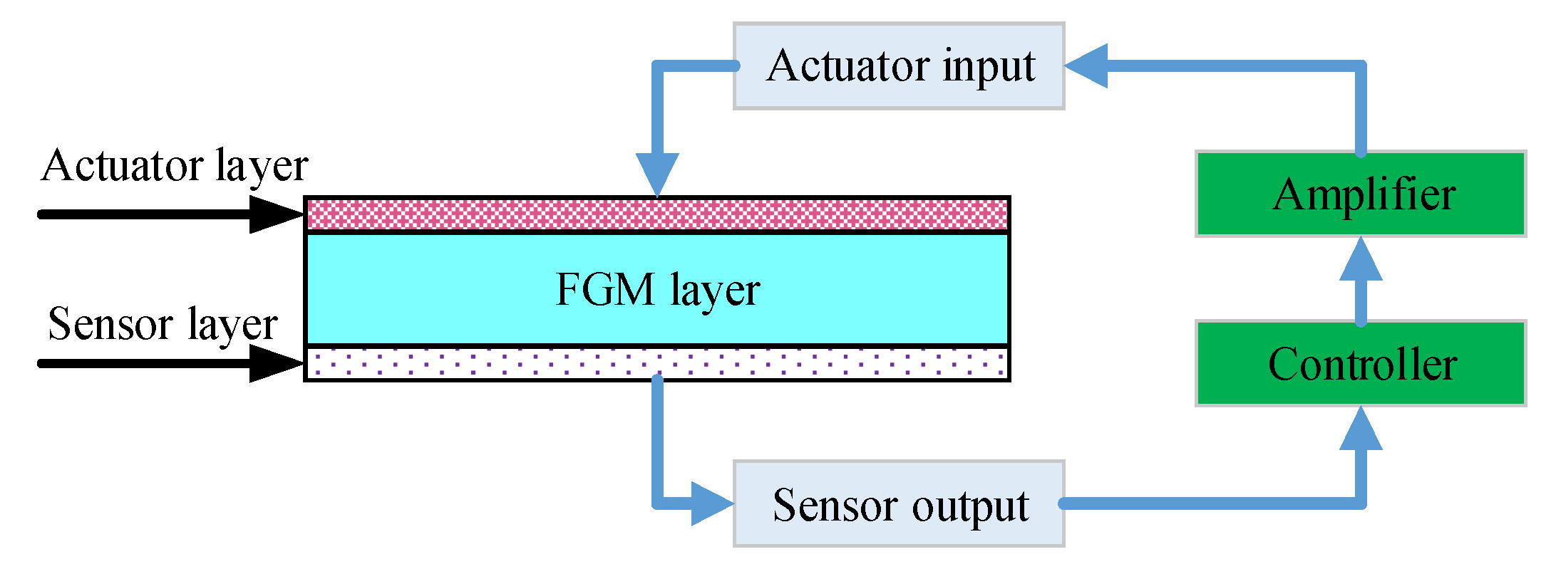
In this section, the static and dynamic closed-loop control of the FGPs by using piezoelectric sensors and actuators are studied. As shown in Figure 3, the upper piezoelectric layer serves as an actuator, and the lower piezoelectric layer serves as a sensor. The sensor generates electric charges because of the piezoelectric effect when the structure deforms. Then, these electric charges are amplified as the input voltage of the actuator. On account of the converse piezoelectric effect, the actuator exerts a force opposite to the external mechanical loads to suppress the static bending or dynamic vibration of the structure, achieving the purpose of active control.
According to the prior analysis, (29b) can be rewritten as
K φ u a d K φ φ a φ a = f φ a ,
K φ u s d K φ φ s φ s = f φ s ,
where the subscripts a and s represent the terms associated with the actuator and sensor, respectively.
Using the feedback control law [43], φ a is expressed as
φ a = G d φ s + G v φ ˙ s ,
where G d and G v are the displacement and velocity feedback control gain, respectively.
For the sensor layer, it is assumed that there is no external charge f φ s , ignoring the converse piezoelectric effect. From (40), the voltage generated on the sensor layer can be defined as
φ s = K φ φ s 1 K φ u s d s .
From (41), (42), and (39), the charge of the actuator layer can be derived by
f φ a = K φ u a d a G d K φ φ a K φ φ s 1 K φ u s d s G v K φ φ a K φ φ s 1 K φ u s d ˙ s .
From (43) and (37), the governing equation is rewritten as
M u u d ¨ + ( C R + C ) d ˙ + K ¯ d = F ,
in which
K ¯ = K u u + G d K φ φ a K φ φ s 1 K φ u s ,
and the active damping matrix C is
C = G v K φ φ a K φ φ s 1 K φ u s .

4. Numerical Results

The order of the NURBS basis functions should be equal to or greater than two to satisfy the requirement of C 1 continuity in approximate formulations [44]. Hence, the orders of the 2D NURBS basis functions in this study are set to be three ( p = q = 3 ). For convenience, the plate’s mechanical boundary conditions are simplified as S, C, and F, where S represents the simply supported edge, with C and F representing the clamped edge and free edge, respectively. The dynamic responses and active vibration analysis of the plate are calculated via the Newmark-β direct integration method.

4.1. Convergence and Verification Studies

The convergence of the present method is verified via the calculation of the natural frequencies of a SSSS square PFGP. The dimensions of the PFGP as depicted in Figure 1 are: a = b = 400 mm, h f = 5 mm, and h p = 0.1 mm. The materials of FGP and piezoelectric layer are Ti-6A1-4V/aluminum oxide and PZT-G1195N. All the material properties are displayed in Table 1.
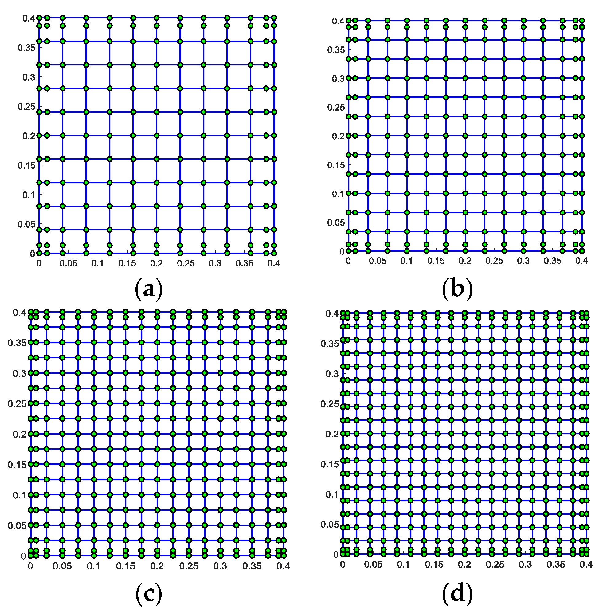
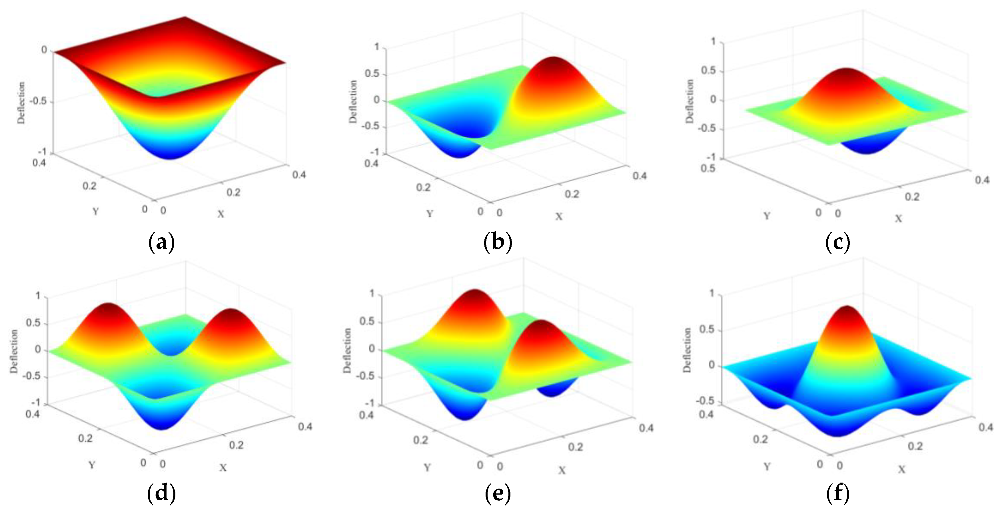
The four different control meshes of 10 × 10, 12 × 12, 16 × 16, and 18 × 18 are shown in Figure 4. Table 2 lists the lowest 10 natural frequencies of the plate. It is seen that the natural frequencies calculated with the 16 × 16 mesh match well with the analytical solutions [45]. Furthermore, the effects on the natural frequency of each mode are not significant when the mesh level is greater than 16 × 16. As a result, the 16 × 16 mesh and cubic NURBS basis functions are applied to all numerical subsequent examples. Figure 5 shows the first six mode shapes of the PFGP with a gradient index n = 2 .

4.2. Free Vibration Analysis

For investigating the effects of the electrical boundary conditions on natural frequencies of the PFGP, a SSSS PFGP with different ratios of h f / a and h p / h f is taken into consideration for comparison. In the closed circuit, two piezoelectric layers are both grounded, while in the open circuit, the electric potential remains free, which implies that there is no electric displacement. The materials of PFGP are Al/Al2O3 and PZT-4, and the material parameters of PZT-4 are defined in [45]. Note that, in this example, n = 0 means that the FGP consists only of ceramic (Al2O3). Conversely, n = means that the FGP is an isotropic metal (Al) plate. Table 3 lists the natural frequencies of the plate with different dimension scales. Besides, Table 4 shows the lowest six natural frequencies of a square plate with SSSC and SCSC boundary conditions when h f / a = 0.02 and h p / h f = 0.1 . It can be seen that the results from the S-FSDT-based IGA match well with those of the analytical [45] and numerical [25] solutions.

4.3. Static Bending Analysis

A cantilevered (CFFF) square PFGP with the same materials and dimensions as those in Section 4.1 is used for analyzing the static bending responses.
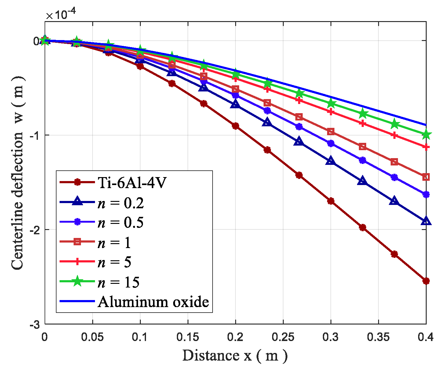
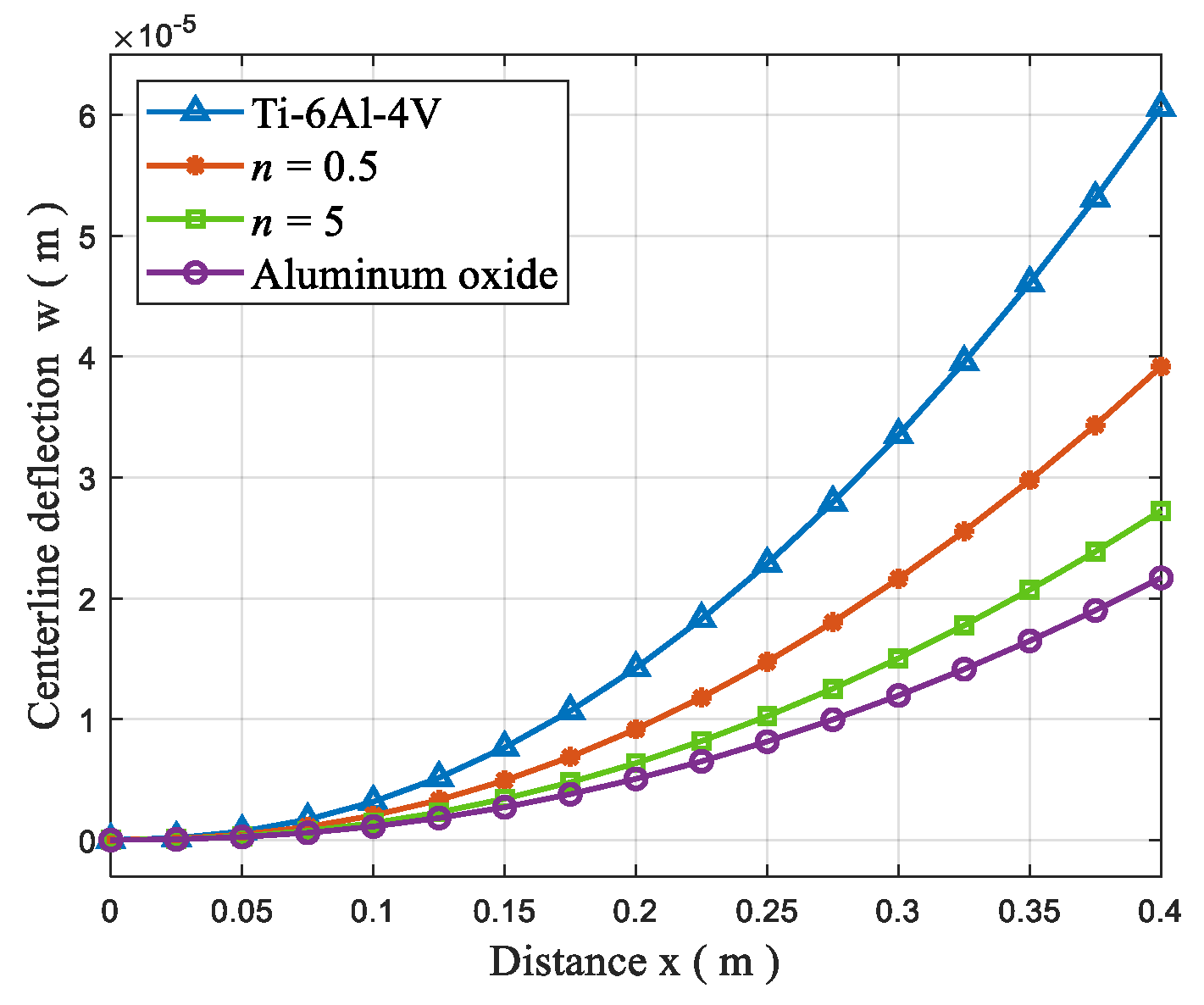
First, the centerline deflection of the plate under a uniformly distributed load of −100 N/m2 is displayed in Figure 6. The deflection obviously decreases when n increases due to the increase in the elastic modulus value E(z) of the FGP.
Next, the centerline deflection of the plate under a 10 V voltage is plotted in Figure 7. This situation involves the open-loop control of the plate, in which both two piezoelectric layers act as actuators. In this situation, the upper piezoelectric layer is polarized in the direction of the applied electric field, and the lower piezoelectric layer is polarized in the opposite direction of the applied electric field. In the case of the converse piezoelectric effect, the upper piezoelectric layer contracts, while the lower piezoelectric layer extends along the direction of the length.
The centerline deflection of the plate under a uniformly distributed load of −100 N/m2 and different input electric voltages is shown in Figure 8. It can be observed that the deflection decreases as the input voltages increase. Meanwhile, Table 5 lists the tip deflection values of the plate. The results in this approach are in good agreement with the solutions in [15].
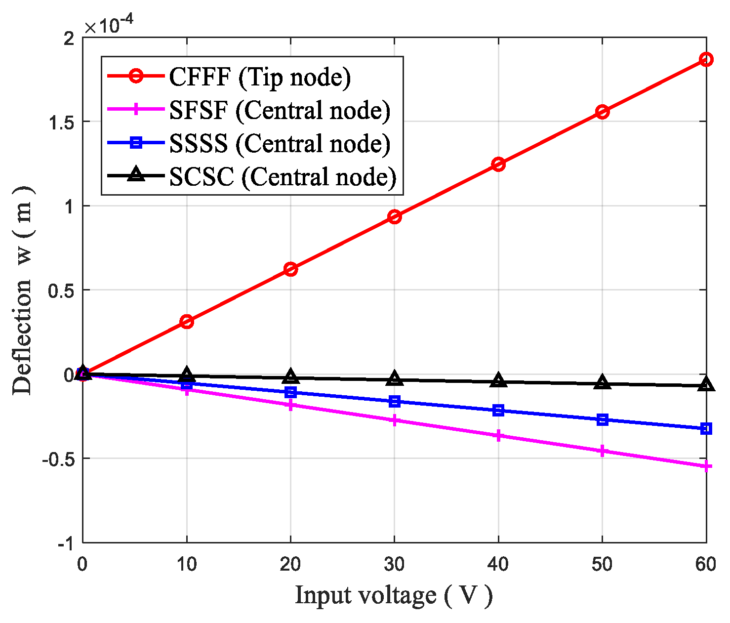
We also investigated the bending response of PFGPs which are subjected to the voltage range 0–60 V with different mechanical boundary conditions. Figure 9 provides the tip deflection or central node deflection of the plate with n = 2 . It is observed that the deflections increase linearly with the increase in the voltage. For the CFFF plate, the deflection is positive, while for the other boundary conditions, the deflections are negative. This phenomenon is due to the upper piezoelectric layer being shortened and the lower piezoelectric layer being elongated due to the converse piezoelectric effect. At the same time, the change of mechanical boundary conditions also results in the change of the deflection direction of the plate.

4.4. Dynamic analysis

A SSSS square FGP (Al/Al2O3) with n = 1 is used for demonstrating the validity of the dynamic analysis with the S-FSDT-based IGA. The length and thickness of the plate are 200 mm and 10 mm. Four different distributed transverse forces are defined as
q = q 0 sin ( π x a ) sin ( π y b ) F ( t ) ,
in which q 0 = 15 Mpa, and F ( t ) is defined as
F ( t ) = { 1 Step   load 1 t / t 1 Triangular   load sin ( π t / t 1 ) Sin usoidal   load e r ¯ t Explosive   load } if   0 t t 1 0 if   t t 1 ,
where γ ¯ = 330 s 1 and t 1 = 0.003 s.
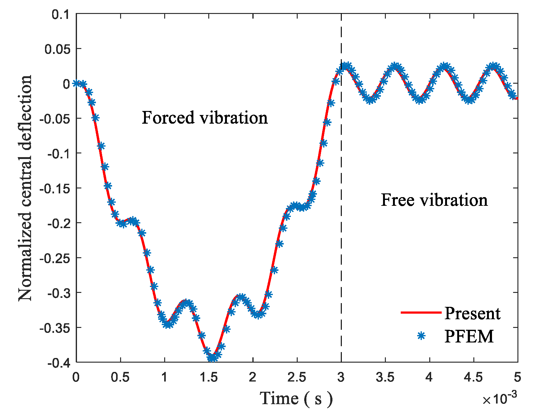
The normalized central transient deflection w ¯ = w / h of the plate under the action of sinusoidal load is depicted in Figure 10. Apparently, the results of this study coincide with those in [46].
Next, a SSSS plate with sizes of a = b = 200 mm, h p = 2 mm, and h f = 20 mm was selected to study the dynamic response of PFGP. The FGM constituents are Ti-6A1-4V and aluminum oxide. The piezoelectric material is PZT-G1195N.
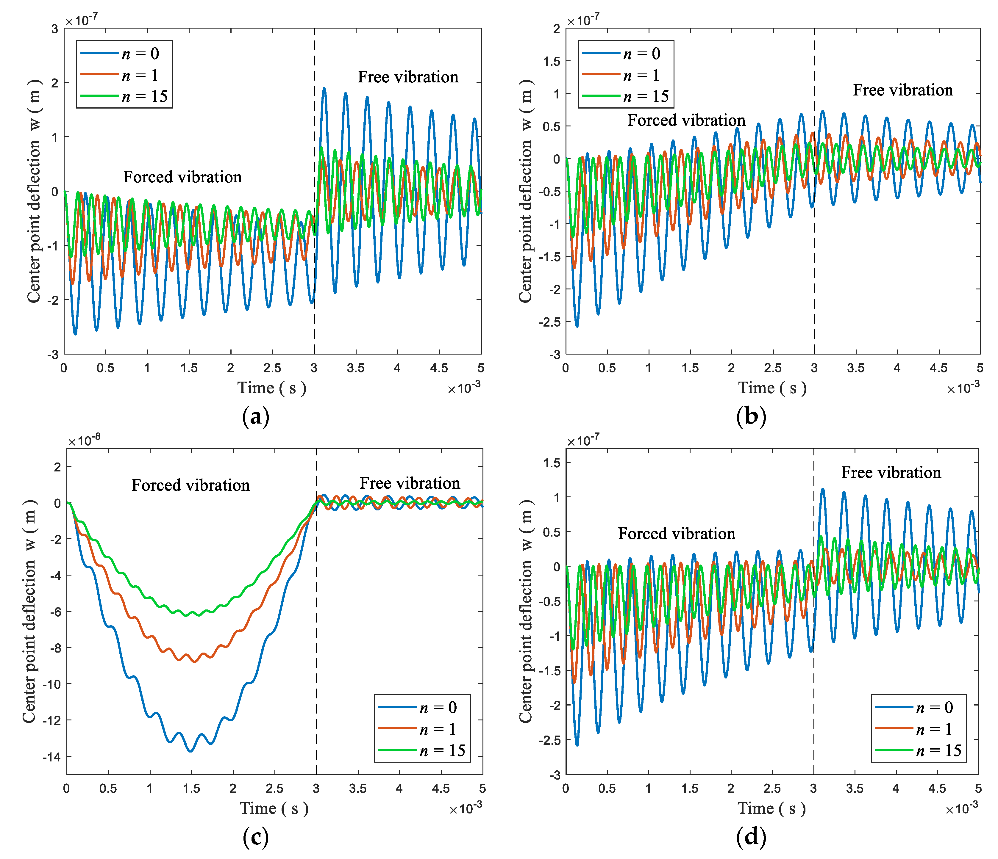
Introducing Rayleigh damping, Figure 11 shows the transient deflections of the plate. It is observed that the vibration amplitude and period of motions decrease with the increase in the gradient index n due to the strengthening of stiffness of the plate.
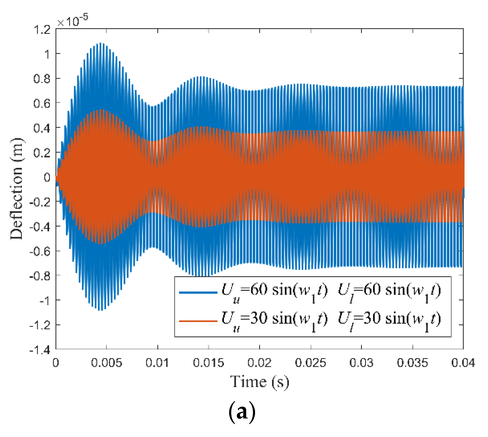
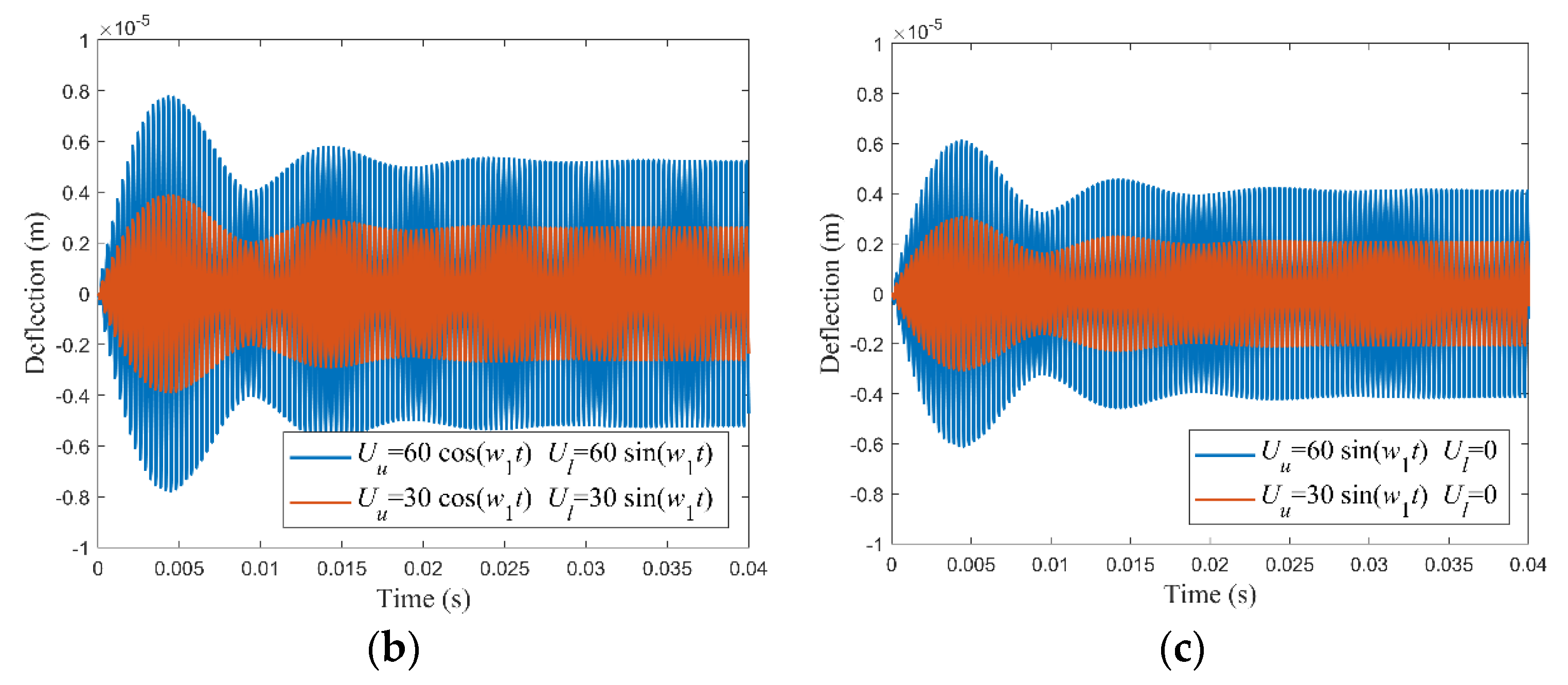
Next, we analyze the dynamic response of PFGPs with n = 2 under the time-varying electric loads. As shown in Figure 12, the magnitude of the voltage amplitude U 0 will affect the vibration amplitude of the plate. Due to the effect of structural damping, the central vibration amplitude of the plate tends to be stable after a period of time. In this example, the time step is set to be 2 π / ( 20 w 1 ) , in which w 1 is the first natural frequency (rad/s) of the plate.

4.5. Active Control Analysis

A square plate and a clamped circular plate are applied for the static bending control analysis and dynamic vibration control analysis of the FGPs through piezoelectric actuators and sensors. The materials of the FGPs and piezoelectric layers in this section are Ti-6Al-4V/aluminum oxide and PZT- G1195N.

4.5.1. Static Bending Control

1. Square plate
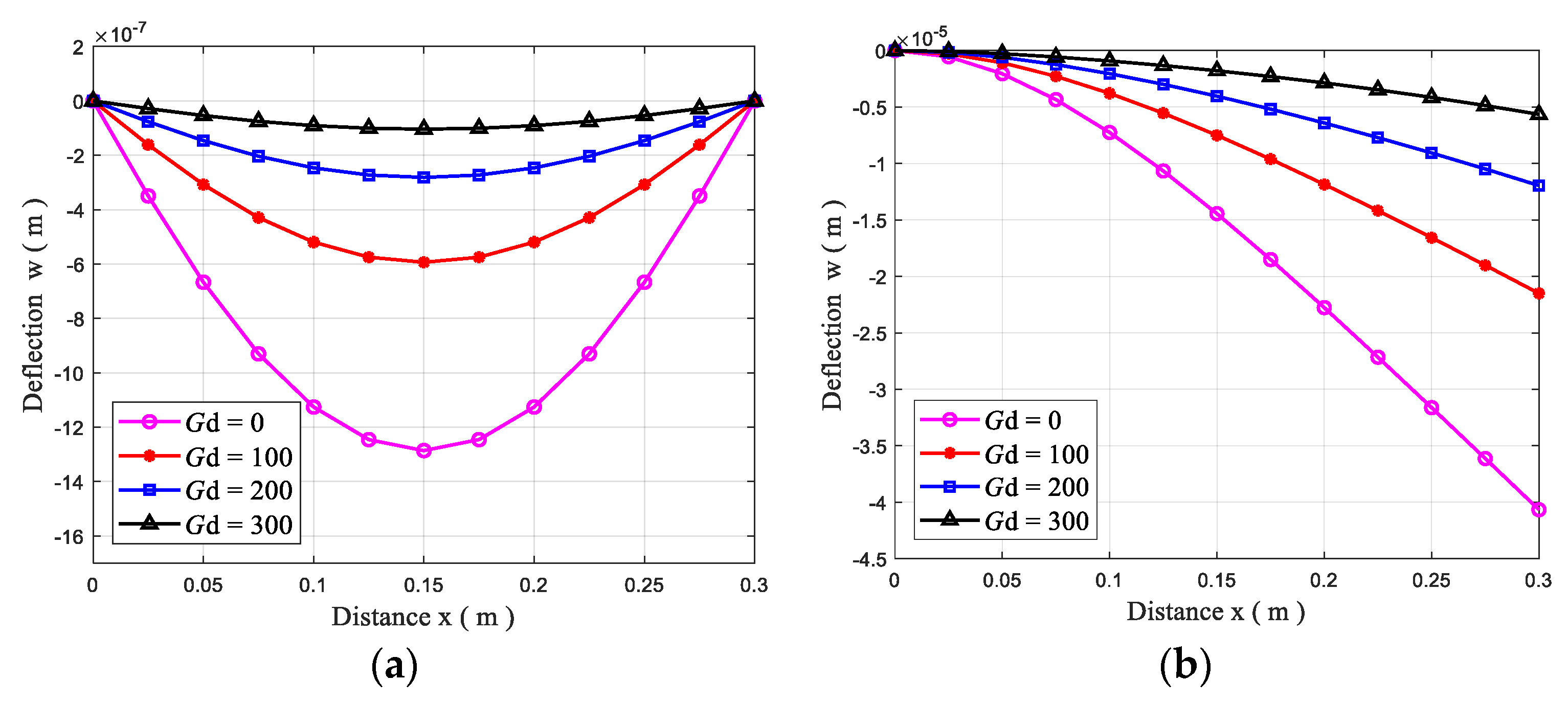
A square PFGP with n = 2 and SSSS and CFFF boundary conditions is used for investigating the static bending control. The dimensions of the plate are set as: a = b = 300 mm, h p = 0.1 mm, and h f = 5 mm. The effects of the displacement feedback control gain G d on the plate’s static bending response under a uniformly distributed load of q = 100 N/m2 are plotted in Figure 13. As expected, the centerline deflections of the plates decrease with the increase in the gain G d .
2. Circular plate
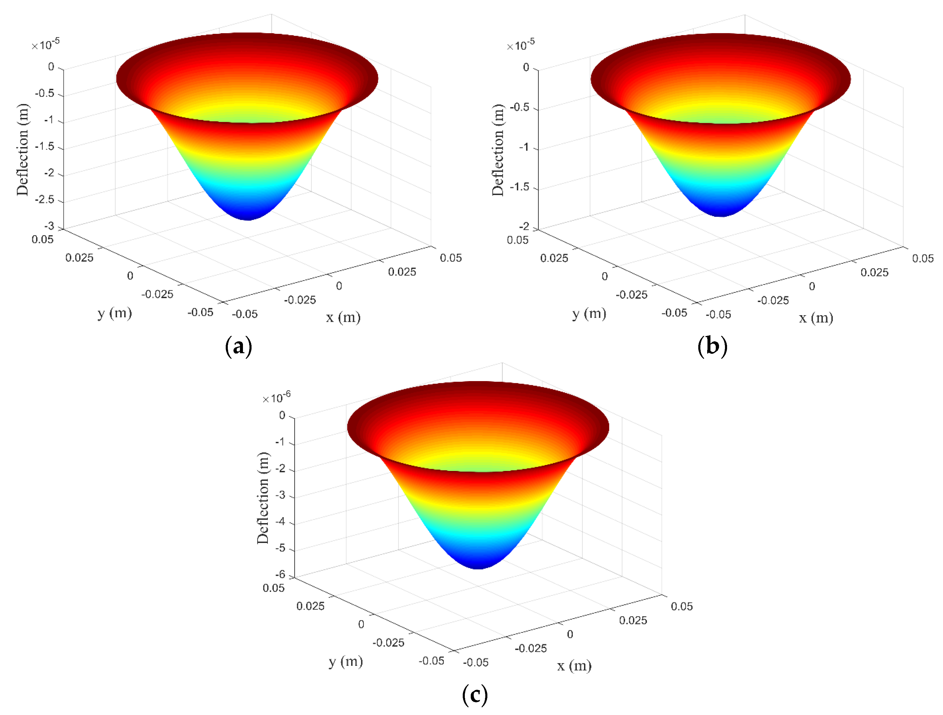
A clamped circular PFGP with n = 2 is also considered. The thicknesses of the plate and each piezoelectric layer are 0.3 mm and 0.05 mm. The radius R is 50 mm. Figure 14 shows the deformation of the plate under a mechanical load of −100 N/m2. We can see that the deformation of the circular plate can also be effectively controlled by G d .

4.5.2. Dynamic Vibration Control

1. Square plate
First, we assume that the former square CFFF PFGP is initially subjected to a downward uniformly distributed load of −100 N/m2, then the load is instantaneously removed, resulting in the motion from the initial displacement. The piezoelectric stress constants e 31 and e 32 are 6.1468 C/m2, and the Rayleigh damping C R of the plate is not considered in this example.
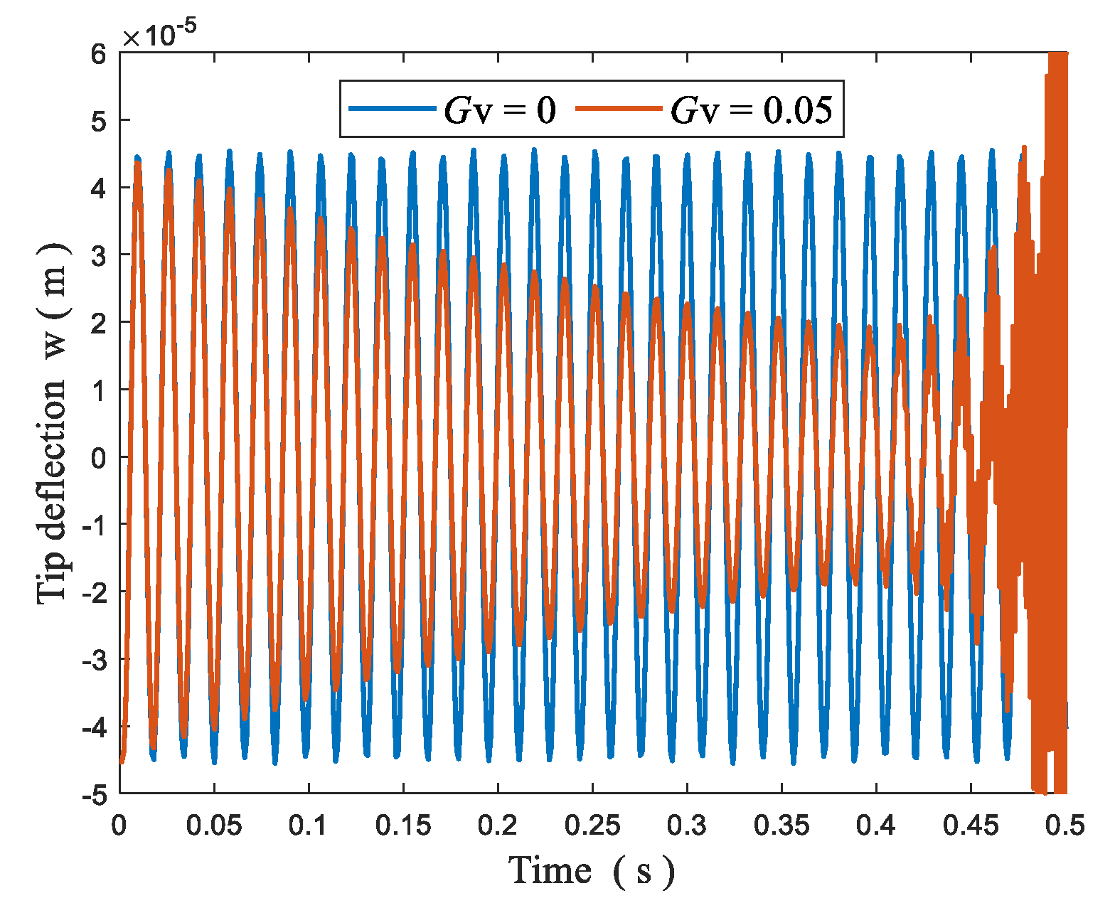
If the stretching–bending coupling effect exists, the active damping C ( C = G v K φ φ a K φ φ s 1 K φ u s ) is not a symmetric positive definite matrix [25,47]. As shown in Figure 15, the dynamic vibration control of plate structures with piezoelectric layers symmetrically distributed on the upper and lower surfaces may be unstable. The main purpose of introducing the neutral surface in this paper is to solve the instability of dynamic vibration control for this sort of plate structure.
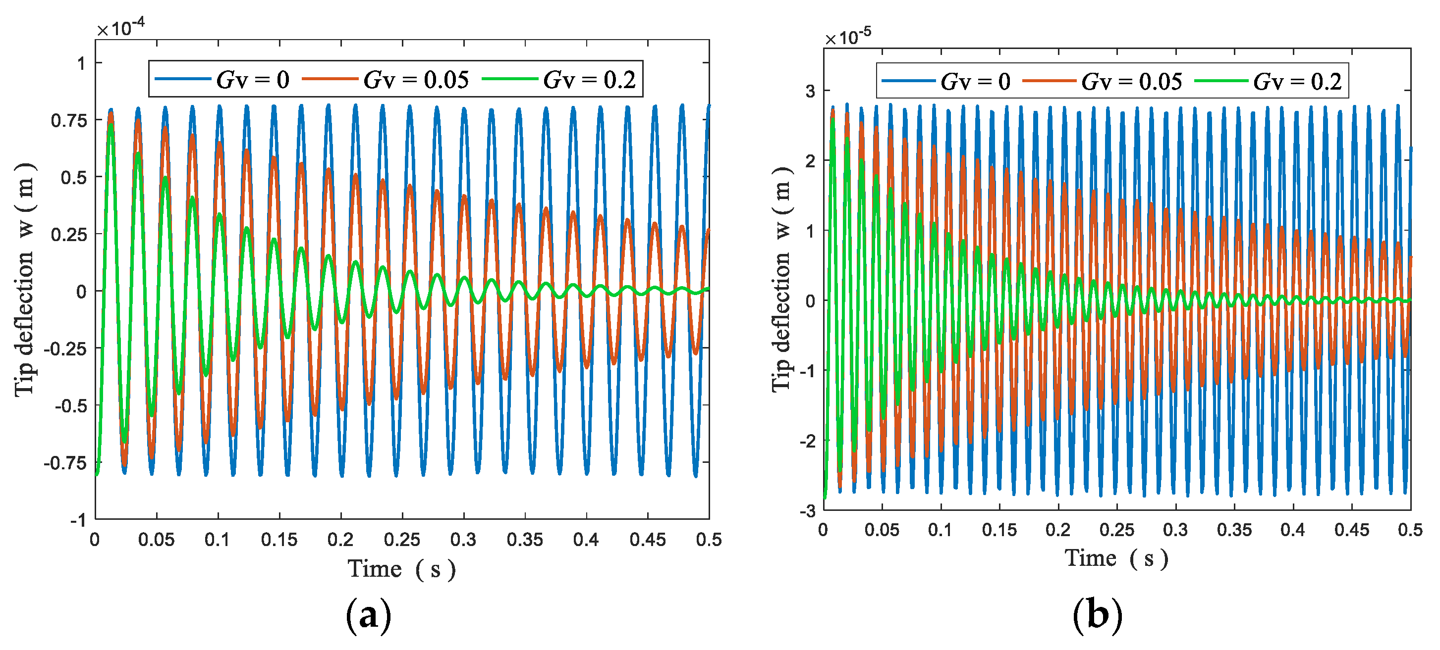
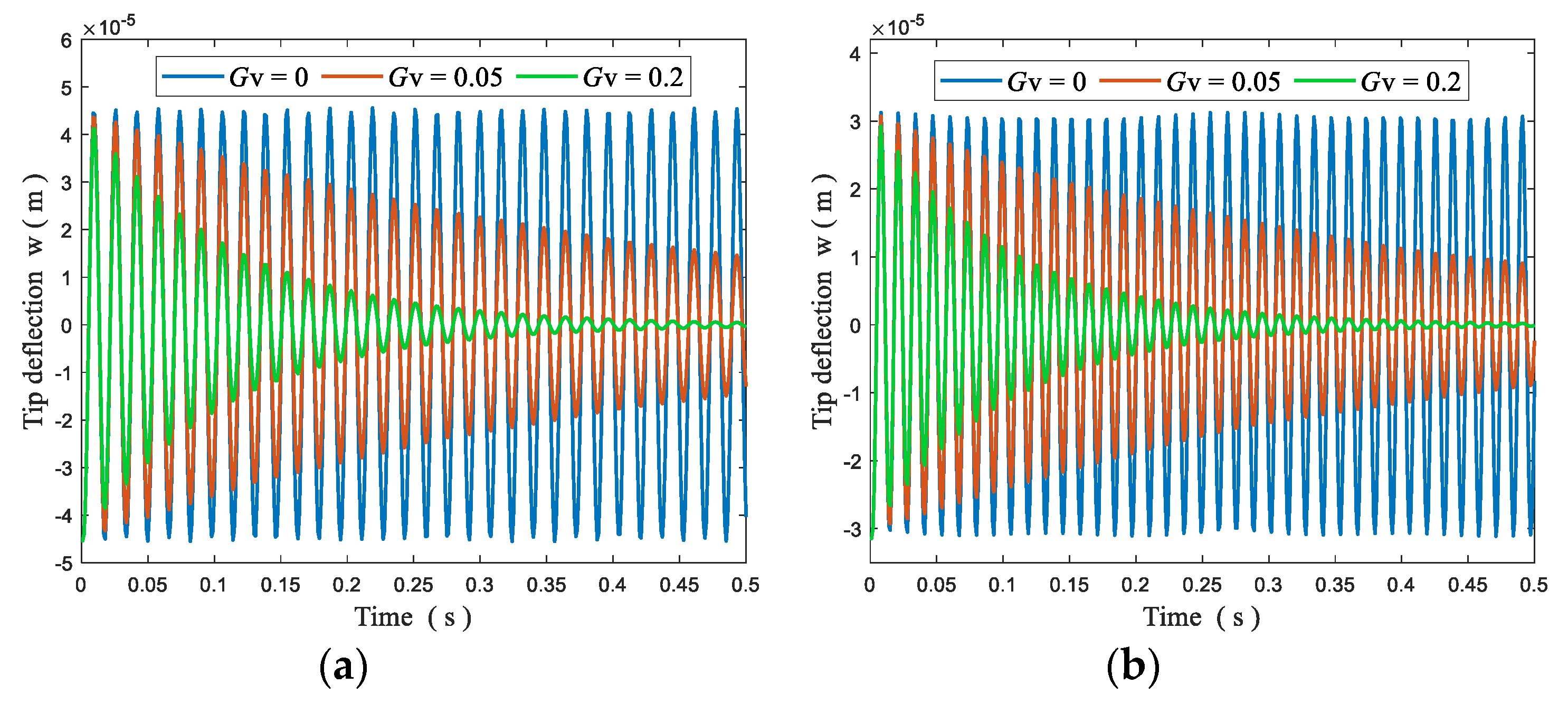
Figure 16 shows the transient deflection response at the tip of the PFGP with n = 0 and n = by using the neutral surface. It is clear that the vibration response attenuates faster when the control gain G v increases and the results match well with the mesh-free method presented by Selim et al. [25]. It is noteworthy that the stretching–bending coupling effect does not exist when n = 0 and n = . Similarly, Figure 17 depicts the transient deflection of the PFGP with n = 1 and n = 15 , and we can see that the dynamic vibration control effect is still stable.
Next, a fully clamped (CCCC) square PFGP is used for studying the active vibration control under four different sinusoidally distributed transverse forces defined in (47) with q 0 = 1 × 10 4 N/m2. The length of the plate is 200 mm, and the thicknesses of the FGP and each piezoelectric layer are 20 mm and 2 mm, respectively.
The transient deflection responses of the central point with different control gains are plotted in Figure 18. Similarly, in both the forced vibration state and free vibration state, the oscillation is significantly suppressed when the control gain G v increases.
2. Circular plate
The circular plate in the section of static bending control is used for further investigation. With the action of an initial uniformly distributed load of −100 N/m2, the time of vibration attenuation to the weakest is investigated in Figure 19. It is observed that the decay time decreases with the increase of n, and the larger the value of G v , the faster the vibration disappears.
Based on the above analysis, we can conclude that the static deformation and the vibration of FGPs can be effectively controlled by using the displacement feedback control gain G d and the velocity feedback control gain G v . By using this feature, controllers can be designed and optimized according to the requirements of different applications to control both the displacement and oscillation time.

5. Conclusions

In this study, an isogeometric analysis method (IGA) based on a simple first-order shear deformation theory (S-FSDT) was used for investigating the free vibration, static bending response, dynamic response, and active control analysis of FGPs with surface-bonded piezoelectric actuators and sensors. Through some numerical examples, several major points can be drawn as follows:
The isogeometric finite element motion equations of piezoelectric functionally graded plates (PFGPs) based on the simple first-order shear deformation theory can be derived easily, due to one unknown saved in S-FSDT.
From some comparison studied of free vibration and static bending analyses of piezoelectric functionally graded plates, it can be obtained that although one unknown is saved in simple first-order shear deformation theory, the S-FSDT-based IGA method is still effective and accurate.
Due to the electromechanical coupling effect, the natural frequencies of the piezoelectric functionally graded plates in open-circuit state are greater than those in closed-circuit state.
The vibration amplitude tends to be stable after a period of time when the plate is subjected to time-varying electric loads; the greater the amplitude of the voltage, the greater the amplitude of the vibration.
For closed-loop control analysis of the plates, the static bending response can be altered by adjusting the displacement feedback control gain G d , and the dynamic vibration and vibration time can be controlled through the velocity feedback control gain G v .

Author Contributions

Conceptualization, T.L.; methodology, C.W.; software, T.L. and C.W.; validation, C.L., J.W.L. and K.H.C.; formal analysis, T.L.; investigation, K.H.C.; resources, C.W.; data curation, C.L.; writing—original draft preparation, T.L.; writing—review and editing, T.L. and K.H.C. All authors have read and agreed to the published version of the manuscript.

Funding

This research was funded by University Synergy Innovation Program of Anhui Province, grant number GXXT-2019-04, National Key Technologies Research & Development Program of China, grant number 2017YFC0805100, Scientific Research Foundation of Education Department of Anhui Province, grant numbers KJ2018A0069, KJ2019A0091 and Singapore University of Technology and Design, grant numbers SRG SCI 2019 142.

Conflicts of Interest

The authors declare no conflict of interest

Nomenclature

a Plate length N In-plane forces
b Plate width M Moments
h t Total thickness of the plate P Shear forces
h f Thickness of the FGM layer f z Transverse mechanical surface load
h p Thickness of each piezoelectric layer M P Moments generated by electric field
P Material properties of FGM B φ Relation matrix between electric field and electric potential
P m Material properties of metal constituent d Displacement vector after assembling the elements
P c Material properties of ceramic constituent u Displacement vector
V m Volume fraction of metal u ˙ First time derivative of u
n Gradient index q s Surface charge
D Electrical displacement f s Surface loads
g Permittivity constant matrix M u u Mass matrix
z 0 Distance between the mid and neutral surfaces d ¨ Second time derivative of d
ε ˜ Geometric strain d ˙ First time derivative of d
ε In-plane strains E Electric field
γ Shear strains K φ φ Electric stiffness matrix
β x Rotations of a transverse normal about the y axis N P In-plane forces generated by electric field
β y Rotations of a transverse normal about the x axis q E Charge density on the surface of piezoelectric layer
e Piezoelectric stress constant matrix C Active damping matrix
Q p Elastic constant of piezoelectric materials C R Rayleigh damping
Q f Elastic constant of FGM α R , β R Rayleigh damping factors
k Shear correction factor G d Displacement feedback control gain
ϑ i , j Weight G v Velocity feedback control gain
G , H B-spline basis functions K u φ , K φ u Displacement-electric stiffness matrices
p , q Orders of B-spline basis functions φ k Nodal electric potential vector
d k Displacement vector of control point k K u u Stiffness matrix

References

  1. Zenkour, A.; Hafed, Z.S.; Radwan, A.F. Bending Analysis of Functionally Graded Nanoscale Plates by Using Nonlocal Mixed Variational Formula. Mathematics 2020, 8, 1162. [Google Scholar] [CrossRef]
  2. Sobczak, J.J.; Drenchev, L. Metallic Functionally Graded Materials: A Specific Class of Advanced Composites. J. Mater. Sci. Technol. 2013, 29, 297–316. [Google Scholar] [CrossRef]
  3. Li, Y.-D.; Tang, Z.-C.; Fu, Z.-J. Generalized Finite Difference Method for Plate Bending Analysis of Functionally Graded Materials. Mathematics 2020, 8, 1940. [Google Scholar] [CrossRef]
  4. Tran, L.V.; Thai, C.H.; Nguyen-Xuan, H. An isogeometric finite element formulation for thermal buckling analysis of functionally graded plates. Finite Elem. Anal. Des. 2013, 73, 65–76. [Google Scholar] [CrossRef]
  5. He, X.-T.; Yang, Z.-X.; Li, Y.-H.; Li, X.; Sun, J.-Y. Application of Multi-Parameter Perturbation Method to Functionally-Graded, Thin, Circular Piezoelectric Plates. Mathematics 2020, 8, 342. [Google Scholar] [CrossRef] [Green Version]
  6. Milazzo, A.; Orlando, C. An equivalent single-layer approach for free vibration analysis of smart laminated thick composite plates. Smart Mater. Struct. 2012, 21, 75031. [Google Scholar] [CrossRef]
  7. Yiqi, M.; Yiming, F. Nonlinear dynamic response and active vibration control for piezoelectric functionally graded plate. J. Sound Vib. 2010, 329, 2015–2028. [Google Scholar] [CrossRef]
  8. Jadhav, P.A.; Bajoria, K.M. Buckling of piezoelectric functionally graded plate subjected to electro-mechanical loading. Smart Mater. Struct. 2012, 21, 105005. [Google Scholar] [CrossRef]
  9. Ray, M.; Sachade, H. Finite element analysis of smart functionally graded plates. Int. J. Solids Struct. 2006, 43, 5468–5484. [Google Scholar] [CrossRef] [Green Version]
  10. Loja, M.A.R.; Soares, C.M.M.; Barbosa, J. Analysis of functionally graded sandwich plate structures with piezoelectric skins, using B-spline finite strip method. Compos. Struct. 2013, 96, 606–615. [Google Scholar] [CrossRef] [Green Version]
  11. He, X.; Ng, T.; Sivashanker, S.; Liew, K. Active control of FGM plates with integrated piezoelectric sensors and actuators. Int. J. Solids Struct. 2001, 38, 1641–1655. [Google Scholar] [CrossRef]
  12. Liew, K.; He, X.Q.; Ng, T.Y.; Sivashanker, S. Active control of FGM plates subjected to a temperature gradient: Modelling via finite element method based on FSDT. Int. J. Numer. Methods Eng. 2001, 52, 1253–1271. [Google Scholar] [CrossRef]
  13. Liew, K.; Sivashanker, S.; He, X.Q.; Ng, T.Y. The modelling and design of smart structures using functionally graded materials and piezoelectrical sensor/actuator patches. Smart Mater. Struct. 2003, 12, 647–655. [Google Scholar] [CrossRef]
  14. Aryana, F.; Bahai, H.; Mirzaeifar, R.; Yeilaghi, A. Modification of dynamic characteristics of FGM plates with integrated piezoelectric layers using first- and second-order approximations. Int. J. Numer. Methods Eng. 2007, 70, 1409–1429. [Google Scholar] [CrossRef]
  15. Nguyen-Quang, K.; Dang-Trung, H.; Ho-Huu, V.; Luong-Van, H.; Nguyen-Thoi, T. Analysis and control of FGM plates integrated with piezoelectric sensors and actuators using cell-based smoothed discrete shear gap method (CS-DSG3). Compos. Struct. 2017, 165, 115–129. [Google Scholar] [CrossRef]
  16. Nguyen-Thoi, T.; Phung-Van, P.; Nguyen-Xuan, H.; Thai-Hoang, C. A cell-based smoothed discrete shear gap method using triangular elements for static and free vibration analyses of Reissner-Mindlin plates. Int. J. Numer. Methods Eng. 2012, 91, 705–741. [Google Scholar] [CrossRef]
  17. Fakhari, V.; Ohadi, A.; Yousefian, P. Nonlinear free and forced vibration behavior of functionally graded plate with piezoelectric layers in thermal environment. Compos. Struct. 2011, 93, 2310–2321. [Google Scholar] [CrossRef]
  18. Fakhari, V.; Ohadi, A. Nonlinear vibration control of functionally graded plate with piezoelectric layers in thermal environment. J. Vib. Control. 2010, 17, 449–469. [Google Scholar] [CrossRef]
  19. Nguyen, N.V.; Lee, J.; Nguyen-Xuan, H. Active vibration control of GPLs-reinforced FG metal foam plates with piezoelectric sensor and actuator layers. Compos. Part B Eng. 2019, 172, 769–784. [Google Scholar] [CrossRef]
  20. Belinha, J.; Araújo, A.; Ferreira, A.J.M.; Dinis, L.; Natal, R.M. The analysis of laminated plates using distinct advanced discretization meshless techniques. Compos. Struct. 2016, 143, 165–179. [Google Scholar] [CrossRef]
  21. Sladek, J.; Stanak, P.; Han, Z.D.; Sladek, V.; Atluri, S.N. Applications of the MLPG method in engineering & sciences: A review. Comput. Model Eng. 2013, 92, 423–475. [Google Scholar]
  22. Dai, K.; Liu, G.; Han, X.; Lim, K.-M. Thermomechanical analysis of functionally graded material (FGM) plates using element-free Galerkin method. Comput. Struct. 2005, 83, 1487–1502. [Google Scholar] [CrossRef]
  23. Chen, X.; Zhao, Z.; Liew, K. Stability of piezoelectric FGM rectangular plates subjected to non-uniformly distributed load, heat and voltage. Adv. Eng. Softw. 2008, 39, 121–131. [Google Scholar] [CrossRef]
  24. Nourmohammadi, H.; Behjat, B. Geometrically nonlinear analysis of functionally graded piezoelectric plate using mesh-free RPIM. Eng. Anal. Bound. Elem. 2019, 99, 131–141. [Google Scholar] [CrossRef]
  25. Selim, B.; Zhang, L.; Liew, K. Active vibration control of FGM plates with piezoelectric layers based on Reddy’s higher-order shear deformation theory. Compos. Struct. 2016, 155, 118–134. [Google Scholar] [CrossRef]
  26. Hughes, T.; Cottrell, J.; Bazilevs, Y. Isogeometric analysis: CAD, finite elements, NURBS, exact geometry and mesh refinement. Comput. Methods Appl. Mech. Eng. 2005, 194, 4135–4195. [Google Scholar] [CrossRef] [Green Version]
  27. Phung-Van, P.; Tran, L.V.; Ferreira, A.J.M.; Nguyen-Xuan, H.; Wahab, M.A. Nonlinear transient isogeometric analysis of smart piezoelectric functionally graded material plates based on generalized shear deformation theory under thermo-electro-mechanical loads. Nonlinear Dyn. 2017, 87, 879–894. [Google Scholar] [CrossRef]
  28. Van, P.P.; De Lorenzis, L.; Thai, C.H.; Wahab, M.A.; Nguyen-Xuan, H. Analysis of laminated composite plates integrated with piezoelectric sensors and actuators using higher-order shear deformation theory and isogeometric finite elements. Comput. Mater. Sci. 2015, 96, 495–505. [Google Scholar] [CrossRef]
  29. Van, P.P.; Nguyen, L.B.; Tran, L.V.; Dinh, T.D.; Thai, C.H.; Bordas, S.; Wahab, M.A.; Nguyen-Xuan, H. An efficient computational approach for control of nonlinear transient responses of smart piezoelectric composite plates. Int. J. Non-Linear Mech. 2015, 76, 190–202. [Google Scholar] [CrossRef] [Green Version]
  30. Nguyen, L.B.; Nguyen, N.V.; Thai, C.H.; Ferreira, A.; Nguyen-Xuan, H. An isogeometric Bézier finite element analysis for piezoelectric FG porous plates reinforced by graphene platelets. Compos. Struct. 2019, 214, 227–245. [Google Scholar] [CrossRef]
  31. Nguyen-Quang, K.; Vo-Duy, T.; Dang-Trung, H.; Nguyen-Thoi, T. An isogeometric approach for dynamic response of laminated FG-CNT reinforced composite plates integrated with piezoelectric layers. Comput. Methods Appl. Mech. Eng. 2018, 332, 25–46. [Google Scholar] [CrossRef]
  32. Lv, Q.; Yao, Z.; Li, X. Contact analysis and experimental investigation of a linear ultrasonic motor. Ultrasonics 2017, 81, 32–38. [Google Scholar] [CrossRef] [PubMed]
  33. Wang, G.; Li, C.; Yuan, T. Design and experiment of a small-scale walking robot employing stick-slip motion principle. Rev. Sci. Instrum. 2017, 88, 115001. [Google Scholar] [CrossRef]
  34. Trabelsi, S.; Frikha, A.; Zghal, S.; Dammak, F. A modified FSDT-based four nodes finite shell element for thermal buckling analysis of functionally graded plates and cylindrical shells. Eng. Struct. 2019, 178, 444–459. [Google Scholar] [CrossRef]
  35. Thai, H.-T.; Kim, S.-E. A simple higher-order shear deformation theory for bending and free vibration analysis of functionally graded plates. Compos. Struct. 2013, 96, 165–173. [Google Scholar] [CrossRef]
  36. Thai, H.-T.; Choi, D.-H. A simple first-order shear deformation theory for laminated composite plates. Compos. Struct. 2013, 106, 754–763. [Google Scholar] [CrossRef]
  37. Yin, S.; Hale, J.S.; Yu, T.; Bui, T.Q.; Bordas, S.P. Isogeometric locking-free plate element: A simple first order shear deformation theory for functionally graded plates. Compos. Struct. 2014, 118, 121–138. [Google Scholar] [CrossRef] [Green Version]
  38. Yu, T.T.; Yin, S.; Bui, T.Q.; Hirose, S. A simple FSDT-based isogeometric analysis for geometrically nonlinear analysis of functionally graded plates. Finite Elem. Anal. Des. 2015, 96, 1–10. [Google Scholar] [CrossRef]
  39. Zhang, D.-G.; Zhou, H.-M. Nonlinear bending analysis of FGM circular plates based on physical neutral surface and higher-order shear deformation theory. Aerosp. Sci. Technol. 2015, 41, 90–98. [Google Scholar] [CrossRef]
  40. Wang, C.; Koh, J.M.; Yu, T.; Xie, N.-G.; Cheong, K.H. Material and shape optimization of bi-directional functionally graded plates by GIGA and an improved multi-objective particle swarm optimization algorithm. Comput. Methods Appl. Mech. Eng. 2020, 366, 113017. [Google Scholar] [CrossRef]
  41. Wang, S. A finite element model for the static and dynamic analysis of a piezoelectric bimorph. Int. J. Solids Struct. 2004, 41, 4075–4096. [Google Scholar] [CrossRef]
  42. Chowdhury, I.; Dasgupta, S.P. Computation of Rayleigh damping coefficients for large systems. Electron. J. Geotech. Eng. 2013, 8, 1–11. [Google Scholar] [CrossRef]
  43. Liu, G.R.; Dai, K.Y.; Lim, K.M. Static and vibration control of composite laminates integrated with piezoelectric sensors and actuators using the radial point interpolation method. Smart Mater. Struct. 2004, 13, 1438–1447. [Google Scholar] [CrossRef]
  44. Tran, L.V.; Ferreira, A.; Nguyen-Xuan, H. Isogeometric analysis of functionally graded plates using higher-order shear deformation theory. Compos. Part B Eng. 2013, 51, 368–383. [Google Scholar] [CrossRef] [Green Version]
  45. Farsangi, M.A.A.; Saidi, A.R. Levy type solution for free vibration analysis of functionally graded rectangular plates with piezoelectric layers. Smart Mater. Struct. 2012, 21, 94017. [Google Scholar] [CrossRef]
  46. Nguyen, N.V.; Nguyen, H.X.; Lee, S.; Nguyen-Xuan, H. Geometrically nonlinear polygonal finite element analysis of functionally graded porous plates. Adv. Eng. Softw. 2018, 126, 110–126. [Google Scholar] [CrossRef]
  47. Wang, S.; Quek, S.; Ang, K. Dynamic stability analysis of finite element modeling of piezoelectric composite plates. Int. J. Solids Struct. 2004, 41, 745–764. [Google Scholar] [CrossRef]
Figure 1. Structure diagram of the PFGP.
Mathematics 08 02177 g001
Figure 2. The volume fraction of the metal V m varies with different n.
Mathematics 08 02177 g002
Figure 3. Diagram of the active control of the functionally graded plate (FGP) with surface-bonded a piezoelectric actuator and sensor.
Mathematics 08 02177 g003
Figure 4. Four different control meshes of a square piezoelectric functionally graded plate (PFGP) with a fully simply supported boundary: (a) 10 × 10; (b) 12 × 12; (c) 16 × 16; (d) 18 × 18.
Mathematics 08 02177 g004
Figure 5. First six mode shapes of a simply supported PFGP: (a) Mode 1; (b) Mode 2; (c) Mode 3; (d) Mode 4; (e) Mode 5; (f) Mode 6.
Mathematics 08 02177 g005
Figure 6. Deflection of a cantilevered PFGP with different gradient index n under the action of a uniformly distributed load.
Mathematics 08 02177 g006
Figure 7. Deflection of a cantilevered PFGP under an input voltage of 10 V with different n .
Mathematics 08 02177 g007
Figure 8. Deflection of a PFGP under the action of electromechanical loads: (a) n = 0; (b) n = 0.5; (c) n = 5; (d) n = ∞.
Mathematics 08 02177 g008
Figure 9. Deflection of a PFGP with different boundary conditions.
Mathematics 08 02177 g009
Figure 10. Transient normalized central deflection of a SSSS FGP with n = 1 .
Mathematics 08 02177 g010
Figure 11. Dynamic analysis of a simply supported (SSSS) PFGP under four different sinusoidally distributed transverse forces: (a) Step load; (b) triangular load; (c) sinusoidal load; (d) explosive load.
Mathematics 08 02177 g011
Figure 12. Transient analysis of a simply supported (SSSS) PFGP when the upper and lower piezoelectric layers are subjected to voltage loads: (a) U u = U l = U 0 sin ( w 1 t ) ; (b) U u = U 0 cos ( w 1 t ) , U l = U 0 sin ( w 1 t ) ; (c) U u = U 0 sin ( w 1 t ) , U l = 0 .
Mathematics 08 02177 g012aMathematics 08 02177 g012b
Figure 13. Static bending control of FGPs through the gain G d : (a) a SSSS plate; (b) a CFFF plate.
Mathematics 08 02177 g013
Figure 14. Static bending control of a circular PFGP through the displacement feedback control gain: (a) G d = 0 ; (b) G d = 5 ; (c) G d = 20 .
Mathematics 08 02177 g014
Figure 15. Tip deflection of a cantilevered plate with n = 1 by using a geometric middle surface.
Mathematics 08 02177 g015
Figure 16. The tip transient deflection of a CFFF PFGP under an initial uniformly distributed load of −100 N/m2: (a) n = 0 ; (b) n = .
Mathematics 08 02177 g016
Figure 17. The tip transient deflection of a CFFF PFGP under an initial uniformly distributed load of −100 N/m2: (a) n = 1 ; (b) n = 15 .
Mathematics 08 02177 g017
Figure 18. Transient deflection responses of a CCCC PFGP under four different time-varying loads: (a) Step load; (b) triangular load; (c) sinusoidal load; (d) explosive load.
Mathematics 08 02177 g018
Figure 19. Time of vibration attenuation to the weakest with different G v .
Mathematics 08 02177 g019
Table 1. Material parameters.
ParametersFGMsPiezoelectric Materials
Ti-6Al-4VAluminum OxideAlAl2O3PZT-G1195N
Young’s modulus (Gpa)
E11105.70320.247038063.0
E22105.70320.247038063.0
E33105.70320.247038063.0
G12----24.2
G13----24.2
G23----24.2
Poisson’s ratio
v120.29810.260.30.30.3
v130.29810.260.30.30.3
v230.29810.260.30.30.3
Density (kg/m3)
𝜌44293750270738007600
Piezoelectric coefficients (m/V)
d31----254 × 10−12
d32----254 × 10−12
Dielectric constant (F/m)
k11----15.3 × 10⁻⁹
k22----15.3 × 10⁻⁹
k33---- 15.0 × 10⁻⁹
Table 2. The lowest 10 natural frequencies (Hz) of a SSSS PFGP with different control meshes.
ModeMethodn
00.515151001000
1IGA (10 × 10)145.355186.550200.615232.411249.284261.318263.696
IGA (12 × 12)145.355186.550200.615232.411249.283261.317263.695
IGA (16 × 16)145.355186.550200.614232.410249.283261.317263.695
IGA (18 × 18)145.355186.550200.614232.410249.283261.317263.695
[45]145.350186.254200.569233.036250.327262.674265.114
2/3IGA (10 × 10)363.085466.002501.155580.604622.741652.785658.721
IGA (12 × 12)363.070465.982501.133580.581622.716652.759658.695
IGA (16 × 16)363.061465.970501.119580.566622.701652.743658.678
IGA (18 × 18)363.060465.968501.117580.563622.698652.740658.676
[45]363.050465.223500.994582.112625.288656.108662.201
4IGA (10 × 10)580.400744.936801.160928.208995.5511043.5531053.035
IGA (12 × 12)580.382744.911801.132928.178995.5201043.5201053.001
IGA (16 × 16)580.371744.895801.115928.160995.5001043.5001052.981
IGA (18 × 18)580.369744.893801.112928.160995.4971043.4961052.977
[45]580.350743.699800.911930.617999.6161048.8571058.589
5/6IGA (10 × 10)725.405931.1041001.4091160.2051244.3481304.3181316.163
IGA (12 × 12)725.196930.8121001.0911159.8611243.9881303.9431315.785
IGA (16 × 16)725.073930.6401000.9041159.6581243.7661303.7211315.561
IGA (18 × 18)725.052930.6121000.8731159.6241243.7411303.6851315.524
[45]725.000929.0781000.5711162.6381248.8191310.3101322.461
7/8IGA (10 × 10)941.9871209.1141300.4551506.7531616.0041693.8401709.211
IGA (12 × 12)941.8181208.8771300.1971506.7411615.7121693.5361708.904
IGA (16 × 16)941.7181208.7381300.0471506.3101615.5401693.3571708.723
IGA (18 × 18)941.7021208.7161300.0221506.2831615.5121693.3271708.694
[45]941.6401206.7401299.6401510.1971622.1021701.9231717.694
9/10IGA (10 × 10)1232.5011582.3511702.0181971.8422114.6492216.3992236.490
IGA (12 × 12)1231.0791580.3321699.8151969.4822112.1912213.8382233.907
IGA (16 × 16)1230.2731579.2001698.5801968.1492110.7992212.3882232.444
IGA (18 × 18)1230.1451579.0211698.3861967.9382110.5792212.1582232.212
[45]1229.8801576.2011697.6171972.7342118.8432223.0212243.603
Table 3. The lowest two natural frequencies (Hz) of a SSSS PFGP with open and closed circuits.
h f / a h p / h f Electrical ConditionModen = 0n = 0.5n = 1
Present[45]Present[45]Present[45]
0.050.1Closed1426.704426.662369.050369.015339.888339.859
21049.6871049.356908.204907.918836.293836.020
Open1433.793433.747377.971377.934350.126350.092
21066.7431066.390929.708929.406860.967860.669
0.2Closed1408.435408.475362.207362.269340.242340.311
21001.3501001.133887.808887.637833.442833.266
Open1421.961421.983378.417378.460358.168358.212
21033.6821033.381926.547926.311876.222875.953
0.10.1Closed1826.873826.463715.679715.319658.905658.555
21954.7691952.5301694.0051691.9921558.8081556.838
Open1840.030839.595732.294731.920677.970677.597
21983.6711981.3211730.7031728.7021600.9481598.821
0.2Closed1786.393786.011697.081696.730654.023653.652
21841.0711838.4751630.9521628.3881527.4671524.747
Open1811.198810.723726.796726.393686.798686.343
21894.7191891.7141695.0631692.7151598.0831595.292
Table 4. The natural frequencies (Hz) of SSSC and SCSC PFGPs.
nModeBoundary Conditions
SSSCSCSC
Open CircuitClosed CircuitOpen CircuitClosed Circuit
Present[25]Present[25]Present[25]Present[25]
01209.750208.651206.281205.550256.565254.251252.330251.120
2457.219454.822449.683448.463484.164480.640476.190474.440
3518.331513.724509.805507.453611.731602.687601.699596.858
4759.533751.930747.075743.357833.053821.085819.420813.141
5883.305876.924868.834866.929900.225892.760885.483882.944
6995.360982.452979.117973.3051131.7131109.4221113.3431101.578
11169.301168.200164.296163.727207.096204.560200.984200.041
2369.044366.401358.167357.223390.797386.889379.288377.936
3418.385413.303406.077404.247493.802483.968493.318475.541
4613.063604.586595.075592.200672.432659.364652.744647.876
5712.952705.039692.056690.600726.615717.565705.327703.381
6803.453788.691779.993775.467913.608889.211887.063877.852
151147.106145.798140.782140.155179.859176.792172.147171.103
2320.364317.022306.656305.467339.173334.267324.677323.006
3362.992356.745347.506345.368428.071416.219409.888405.664
4531.147520.850508.885505.316582.586566.509557.909552.131
5617.872607.441591.657589.345629.633617.822602.937600.054
6695.567677.205666.222660.679789.825760.509756.752746.359
10001132.128130.883125.082124.591161.553158.500152.959152.151
2287.775284.556272.499271.659304.677299.892288.521287.316
3326.083319.956308.822307.247384.572372.904364.300361.092
4477.475467.118452.296449.750523.425507.747495.908491.650
5555.120544.766525.892524.530565.693554.003535.927534.127
6624.981606.883592.251588.375709.757681.066672.853665.183
Table 5. Tip deflection of a CFFF PFGP under the action of electromechanical loads (10−4 m).
nMethodInput Electric Voltages (V)
02040
n = 0[15]−2.5460−1.3346−0.1232
Present−2.5433−1.3323−0.1212
n = 0.5[15]−1.6199−0.8440−0.0681
Present−1.6167−0.8421−0.0675
n = 5[15]−1.1266−0.5820−0.0375
Present−1.1253−0.5811−0.0369
n = ∞[15]−0.8947−0.4609−0.0271
Present−0.8939−0.4602−0.0265
Publisher’s Note: MDPI stays neutral with regard to jurisdictional claims in published maps and institutional affiliations.