1. Introduction
The theoretical study of axisymmetric supercavitating flows started to receive much attention in the middle of the 20th century. One of the motivations was primarily to decrease the drag and increase the speed of bodies moving in a liquid at high speeds [
1,
2,
3]. High-speed motion in water is known to be most efficient in the regimes of developed cavitation or supercavitation. In the latter case, skin friction, which contributes significantly to the total hydrodynamic drag at high speeds, nearly disappears because the vessel moves inside a self-generated bubble of water vapor. Only the nose of the body, or the cavitator, experiences the hydrodynamic drag [
4].
At the same time, for supercavitation flows motion stability control presents a problem. The motion of a body inside a cavity, or vapor bubble, is unstable in nature due to the torque produced by the hydrodynamic drag acting on the cavitator and the inertia force applied at the center of mass, which is located downstream. In addition, there is no buoyancy force acting on the body inside the cavity; therefore, the weight of the body has to be balanced by the hydrodynamic force.
The experiments conducted at the Institute of Hydromechanics of the National Academy of Sciences of Ukraine [
5,
6,
7,
8] at speeds in the range from 400 m/s to 1000 m/s revealed self-stabilizing regimes of supercavitating motions when the gap
h between the projectile and the cavity side is
h < 0.15
D where
D is the diameter of the stern. At larger gaps, 0.15
D <
h < 0.3
D, the rear part of an axisymmetric projectile periodically hits the cavity boundaries.
A schematic of the experimental setup equipped with a photorecording and speed measurement system is shown in
Figure 1.
An electrochemical catapult 2 is installed at the head of a launching tank 1 of length 35 m. The catapult decomposes water into hydrogen and oxygen and uses the energy released in the burning of their mixture for launching models at speeds up to 1550 m/s. At the end of the launching tank, the models were caught with a catcher 4. Supercavitating flow patterns are recorded through twin glass windows 5 by a TV camera 6 using a pulse lighting system 7, 8, 9 with a minimum exposure time of 2 × 10⁻⁶ s. The model speed was measured with contact sensors 11–14, inertia sensors 18, pulse shapers 15, and speed recorders 16.
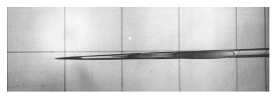
Figure 2a shows the supercavity at the instant when the projectile hits the cavity wall. Since the shape of the supercavity is concave, the stern of the projectile first impacts the supercavity. As the stern penetrates into the liquid, the impacting cross section of the projectile moves some distance towards its nose. Impact marks on the cavity boundary at a later instant can be seen in
Figure 2b. The cross sectional area of the supercavity continuously grows due to the momentum transferred to the liquid by the cavitator when its nose passes the particular cross section. Similarly, the impact marks also continuously grow due to the momentum transferred by the stern part of the projectile at the impact instants. The photographs clearly show that the projectile–liquid interaction is of an impact character.
The dynamics of a supercavitating projectile and its stability were studied in a number of papers [
5,
6,
7,
8,
9,
10,
11,
12]. The mathematical models are based on a set of equations that include the hydrodynamic forces and moments acting on the projectile. The present study is focused on the transverse forces generated due to an impact between the projectile stern and the cavity side.
The pioneering work on water impact problems was the von Karman [
13] impulse solution for a flat plate impacting the flat free surface of a liquid half-space. Further development was done by Wagner [
14], who used Karman’s solution to account for the free surface elevation during the impact. Wagner’s solution is currently widely used in the naval context as a model of various water impact phenomena [
15].
Further development of the impulse theory was done by Cooker and Peregrine ([
16,
17]), who considered finite liquid masses impacting solid structures with application to marine and coastal engineering. Tyvand and Miloh used the impulse theory to study the initial stage of sloshing in open rigid containers [
18]. They also studied the impulsive starting motion of a circular cylinder submerged below the free surface [
19]. Hjelmervik and Tyvand studied impacts of 3D liquid masses on a flat rigid surface [
20].
The problem of a circular cylinder penetrating a cylindrical cavity was considered by Vasin and Paryshev [
21]. They used a conformal mapping of the physical plane onto an auxiliary upper half-plane and formulated a boundary value problem for the velocity potential. The boundary value problem in the auxiliary plane was solved using the Wagner theory. However, no results on the added mass were presented.
The present study is aimed at determining the impulsive force generated by an impact between a body and the free surface inside a cylindrical cavity in an unbounded liquid region. The case of a circular arc of a fixed length is considered. The solution is obtained in the form of integral equations using the integral hodograph method [
22,
23]. The solution may account for an arbitrary shape of the contact area and the free surface. The results are presented in terms of the added mass and the velocity distribution along the cylindrical cavity.
2. Impulse Solution for a Circular Arc Impacting the Free Surface of a Cylindrical Cavity
We consider an impulsive impact between a circular arc of radius
R and angle 2
ϕ and the free surface of a cylindrical cavity. The liquid is assumed to be ideal and incompressible, and the flow is irrotational. Gravity and surface tension effects are ignored. Before the impact, the body and the liquid are at rest. An impact implies giving the body velocity
during infinitely small time interval
by applying force
. In an ideal liquid, only normal pressures can generate a velocity field
during an impact. Therefore, the flow has a potential, and we can apply the Cauchy–Lagrange integral
where
is the velocity potential,
is the velocity magnitude,
and
are the hydrodynamic pressure and the pressure in the cavity, respectively. By integrating Equation (1) over the infinitesimal time interval
and taking into account that the integral of the second term tends to zero as
, one can obtain
where
is the impulse pressure.
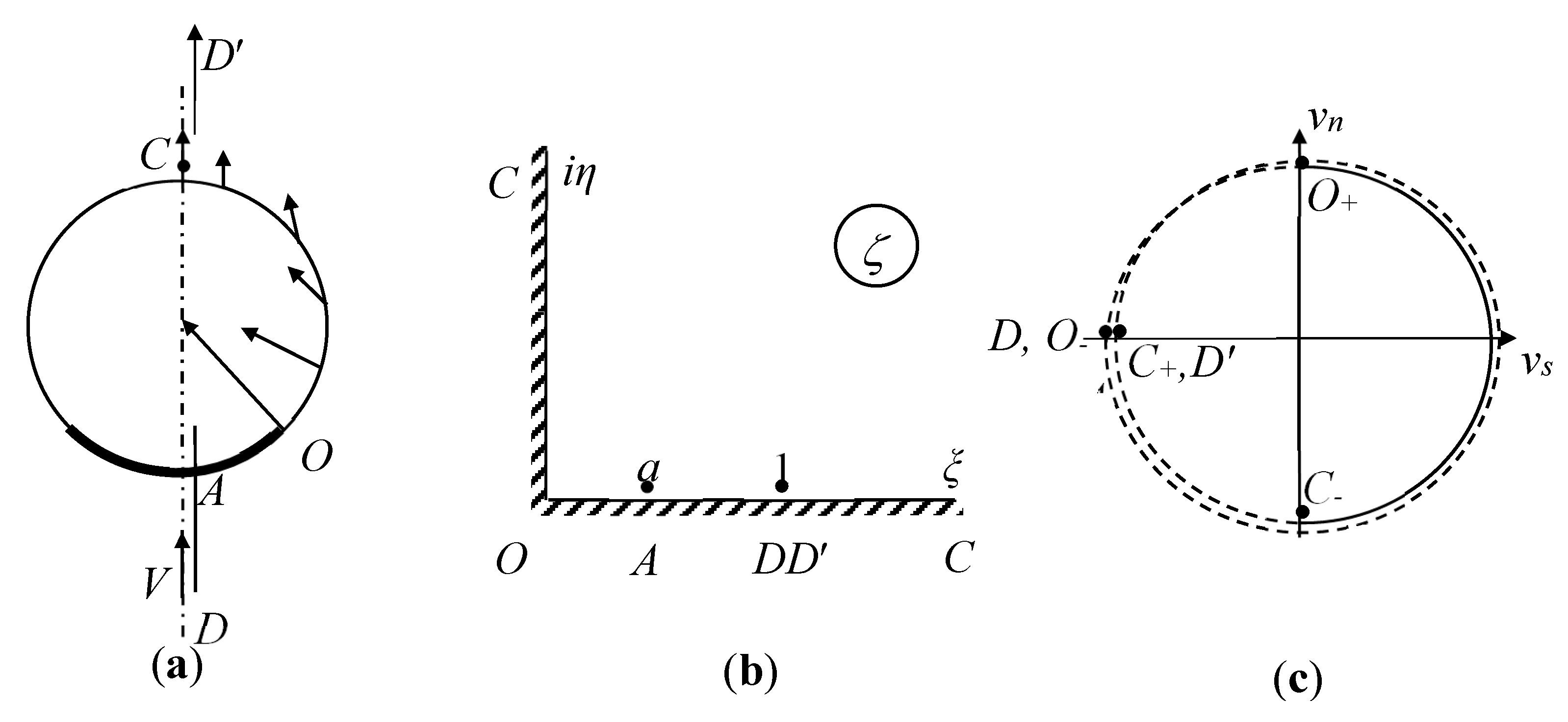
The pressure on the cavity surface is constant and equal to the pressure in the cavity; therefore, the impulse pressure is equal to zero along the free surface. We define a Cartesian system
with its origin at the bottom of the arc. Based on the dynamic equivalence, the body entry speed can be considered zero, and the flow comes from
with velocity
as shown in
Figure 3a.
The problem is to determine the function of the complex potential of the flow,
, that conformally maps the physical plane
onto the complex-velocity potential region
. We will use the integral hodograph method [
22,
23], in which a parameter plane
is introduced. Instead of finding
directly, two complex functions,
, which is the complex velocity, and the function,
, which is the derivative of the complex potential, are sought in the
plane in integral form. Once these two functions are found, the relation between the parameter and physical planes can be determined as follows [
24]:
where
is the position of point
in the physical plane, and
is the derivative of the mapping function
.
Based on the method of Chaplygin (see §5 of Chapter 1 in [
24]), we choose the first quadrant of the
plane shown in
Figure 3b as the parameter region that corresponds to the flow region in the physical plane in
Figure 3a. The functions
and
conformally map the parameter region onto the regions of the planes of the complex velocity and the derivative of the complex potential. Based on the theorem of conformal mapping, three points in the parameter plane can be chosen arbitrarily, which are taken as
(intersection point of the body surface and the free surface),
(point at infinity) and
(stagnation point at the bottom of the arc), as shown in
Figure 3b. The imaginary axis corresponds to the free surface
. The interval
of the real axis corresponds to the circular arc, and the interval
corresponds to the symmetry line
. The rest of the positive real axis (
) corresponds to the symmetry line
. In order to determine the functions
and
, appropriate boundary value problems for each of these functions in the
plane should be formulated.
We assume that the velocity magnitude along the free surface, that is along the positive part of the imaginary axis,
is known. This function will be determined below.
In the frame of reference attached to the arc, the normal velocity component equals zero due to the impermeability condition. Therefore, the argument of the complex velocity along the interval
of the real axis equals
where
is the slope of the arc as a function of the variable
. Using this notation, we can write the function
as follows
The problem is then to find the function
in the first quadrant of the parameter plane that satisfies the given boundary conditions. The Formula [
23]
provides a solution to the mixed boundary-value problem in Equations (5) and (6) in the first quadrant of the complex plane. Here,
and
, are the velocity magnitude and direction at point
. The argument of the complex velocity undergoes a step change at the point
corresponding to the corner at point
in the physical plane. Substituting Equation (6) into the first integral in Equation (7), we finally obtain the expression for the complex velocity in the
plane
It can be seen that the complex velocity function has only one zero of order at the point .
In order to analyze the complex potential, it is useful to introduce unit vectors
and
, which are normal and tangent to the free surface, respectively. The normal vector is directed outside the liquid region while the spatial coordinate along the free surface
increases along the free surface with the liquid region taken on the left (
Figure 3a). With this notation, we have
where
and
are the tangential and normal velocity components, respectively. Let
denote the angle between the velocity vector on the free surface and the unit vector
,
; its behavior along the boundary of the liquid region is shown in
Figure 3c.
The argument of the derivative of the complex potential,
, can be determined on the whole boundary of the flow region as follows
where
The function
decreases from
at point
to
at point
as can be seen in
Figure 3c.
The derivative of the potential can be written in the following integral form [
23]:
where
is a real factor and
. By substituting Equations (10) and (11) into Equation (12) and evaluating the integrals over each step change of the function
at point
(
), we obtain
Equations (8) and (13) include unknown parameters,
,
, and
, which are determined from the following physical considerations. The velocity magnitude at point
(
) is chosen as the reference velocity; therefore, it is equal to 1,
The length of the circular arc is
where
The mass balance between the liquid coming from infinity and that coming into the cavity gives the following equation
where
Equations (8) and (13) contain the unknown functions , , and , which have to be determined from the kinematic boundary condition on the free surface and the wetted surface of the body.
Body surface boundary condition: integro-differential equation in the function.
By integrating Equation (16) along the real axis of the parameter region, we can determine the spatial coordinate
along the body as a function of the parameter variable
. Since the function
is known on the wetted body surface
corresponding to the interval
, the function
is determined from the following equation:
By using
from Equation (16), this equation takes the form
where
is the curvature of the circular arc.
Kinematic boundary condition on the cavity surface: integral equation in the function.
During an impulsive impact, the free surface does not change. The slope of the free surface,
, can be obtained using Equations (3), (8), and (13)
Taking the argument of the complex velocity from Equation (8) at
and the argument of the derivative of the complex potential from Equation (13) substituting the result into Equation (21), we obtain the following integral equation in the function
where
is the velocity angle to the cavity surface, which is determined from the following condition. The velocity generated on the cavity surface during an impulsive impact is perpendicular to the free surface. This fact follows from the Euler equations in the case of a constant pressure along the free surface. Therefore, the tangential component of the velocity remains constant during the impact, or
, wherefrom the function
can be determined
Integrating the impulse pressure in Equation (2) over the body surface, the impulse force
is obtained
where
is the coefficient of added mass of the circular arc, and
Lp =
Rsin
φ is the projection of the arc onto the
x-axis.
3. Results and Discussion
The solution procedure for the system of integral Equations (20) and (22) is based on the method of successive approximations. In discrete form, the solution is sought on a fixed set of points , , distributed along the real axis of the parameter region and on a fixed set of points , , distributed along the imaginary axis as geometric series. In the majority of the calculations below, and . The smallest intervals near the edge of the arc (point ) were chosen as . Equation (20) converges rapidly requiring only a few iterations, while Equation (22) together with (23) takes several hundreds of iterations to reach a tolerance .
Velocity distributions along the cylindrical cavity are shown in
Figure 4 for different angels
of the circular arc. The results are shown in a system of coordinates attached to the calm liquid at infinity. The velocity vectors on the cavity boundary are shown in the figure as thin arrows perpendicular to the fluid boundary. This is consistent with what follows from the Euler equation for the case of a constant pressure on the boundary. The thin arrows directed outside the circle show the velocity of the arc. At the edge of the arc the velocity magnitude tends to infinity. The corresponding arrows are too big, and they are not shown in the figure. The velocity magnitude gradually decreases away from the arc. The velocity reaches its minima at the top point of the cavity. The minimal velocity has some finite value, which tends to zero only if the angle of the arc
. As the angle of the arc increases, the minimal velocity at the top of the cavity also increases. This is due to the fact the liquid displaced by the arc moves inside the cavity. The larger the arc, the larger the liquid volume coming inside the cavity. This increases the velocity along the whole cavity side including the top point of the cavity. As the angle of the arc
becomes smaller, the cavity surface flattens near the arc, and the solution gradually tends to that corresponding to the von Karman solution [
20].
The coefficient of added mass versus the angle of the arc is shown in
Figure 5. As the angle
, the coefficient of added mass
. This is expectable since the ratio of the arc length to the length of the flow boundary
, which corresponds to a flat plate impacting a flat free surface. The coefficient of added mass rapidly decreases even for relatively small values of
. This rapid change of the coefficient of added mass is due to the effect of the velocity angle near the edge of the arc. The larger the angle of the arc, the larger the angle of the velocity at the ends of the arc. Similar results were obtained in the paper [
21], where the water-entry problem for a circular arc is studied using Wagner’s approach. As can be seen in
Figure 5, the coefficient of added mass increases in the range
. This may be due to the fact that the liquid volume displaced into the cavity through the free surface becomes larger, while the length of the free surface becomes smaller. This increases the pressure and the velocity of the liquid throughout the entire flow region and sets a larger liquid volume in motion. This is consistent with the results shown in
Figure 4.
