Article

An Efficient Micro Grid Optimization Theory

1
Department of Electrical and Computer Engineering, Seoul National University, Seoul 08826, Korea
2
Department of Data Informatics, Korea Maritime and Ocean University, Busan 49112, Korea
*
Author to whom correspondence should be addressed.
Mathematics 2020, 8(4), 560; https://doi.org/10.3390/math8040560
Submission received: 15 January 2020 / Revised: 27 March 2020 / Accepted: 28 March 2020 / Published: 10 April 2020
(This article belongs to the Special Issue Mathematics and Engineering)

Abstract

:
A Micro Grid is an aggregate of many small-scale distributed energy resources (DERs); loads and can be operated independently or together with the existing power grid as a local power grid. The operator of such a grid takes charge of the energy supply and consumption of these resources and loads available in the grid. Meanwhile, the system operator of the grid considers the entire Micro Grid system to be a single load or a generator and assigns the responsibility of its internal management to the operator. The power production from a passive production resource is largely influenced by external environmental factors such as weather conditions, rather than operating conditions. Thus, this study conducted simulations for the cases where four kinds of conditional expressions had not been applied at all or one of them had been applied to compare and evaluate the effectiveness of each expression. As a result, the conditional equations were found to be effective when attempting to optimize the Micro Grids efficiently.

1. Introduction

Many small-scale DERs and loads form a Micro Grid, a local power grid that can be operated independently or by tying with the existing power grid [1]. The operator of such grid takes charge of energy supply and consumption for these resources and loads existing within the Micro Grid, whereas the system operator of the grid considers the entire Micro Grid system to be a single load or a generator and assigns the responsibility of its internal management to the operator [2,3,4].
The energy resources in the Micro Grid are largely divided into passive resources that cannot be controlled by the grid operator and active resources controllable by him/her [5]. These resources are also classified as production, consumption or storage resources in terms of their applications [6]. Typical examples of a passive resource include new and renewable energy resources such as solar rays, wind, etc. The power production using these passive resources can be largely affected by external environmental conditions like weather situations rather than the operator-controlled production process.
Although it would be possible to interrupt power production by disconnecting with the Micro Grid’s internal power grid, implementing some kind of control to increase power production arbitrarily is almost impossible as it depends on the external environmental conditions. Even though passive resources have a disadvantage in terms of inability to control, they also have an advantage of being able to achieve eco-friendly power generation without much extra cost after the initial installation cost in majority of the cases. For this reason, these resources are being used as a major power supply resource of a Micro Grid. Their issue of inability to control raises a problem in the balance between power demand and supply, causing sharp fluctuations in it such that an ancillary active resource is often required to solve the problem. One of the most popular passive resources, photovoltaic power generation, has a problem of production variability or excessive production due to its characteristic of insolation-based production. Thus, this study conducted simulations for cases wherein none of the four kinds of conditional equations (i.e., conditional equations for peak control, power use flattening, power demand response and operation of net zero Energy or one of them had been applied to compare them and evaluate the effectiveness of each equation. The result showed that the conditional equations were effective when attempting to optimize the Micro Grids efficiently.

2. Related Research

Typical examples of passive consumption resources of Micro Grid include loads such as household appliances used by the residents on the Micro Grid. Although there are some controllable loads, most of them are used to meet the requirements of residents and beyond the control of Micro Grid operators [7,8].
The active production resources of Micro Grid include fuel cells, combined heat and power generation and most of the other generating facilities that are able to produce power according to the operator’s control. Although these resources require some additional costs (fuel expenses) when generating power, they are indispensable in the operation of a Micro Grid wherein power supply and demand or quality issues should be considered as their power output level can be controlled arbitrarily [9,10,11].
On the other hand, the active consumption resources of Micro Grid include some operator-controllable loads such as lighting fixtures, air-conditioning equipment, etc. Control can be implemented in a way that will not make the residents uncomfortable when attempting to reduce excessive power use in the Micro Grid. Moreover, the active storage resources are useful in keeping the balance between power supply and demand or securing power quality or economy by storing or releasing surplus power. These active storage resources can store or release the desired amount of power in any desired time zone. Likewise, as many of them have rapid responsiveness, it is possible to deal with the variability in power production. Typical examples of these resources include energy storage systems such as batteries, flywheels, combined air energy storage, etc. [12,13].
Meanwhile, Micro Grids are divided into system-connected type or independent type depending on whether they are operating with an external system (power grid) [14]. The grid-connected Micro Grid is operated in a state of establishing a connection with another power system and is able to exchange surplus power to supplement each other. The independent-type Micro Grid (a.k.a. island grid) is operated in a state of separating itself with another power grid and managing the quality (i.e., supply and demand or voltage/current, etc.) by itself. The former can sell the surplus or purchase the power amount lacking by connecting with an external system and some of the typical examples are small-scale building, home and campus Micro Grids. If it is impossible to meet the demand from a consumption resource, these Micro Grids buy the system’s surplus power or sell their own surplus to the system when their production is more than enough.
In addition, an external power rates provision system (e.g., KEPCO or Korea Power Exchange) is necessary to settle the power bills incurred from these transactions, further requiring a metering device connected with an outside system along with the external system or market that will be able to pass on the signals in case of blackout or demand response (DR) [15].
The independent Micro Grid manages the power supply and demand balance or power quality within the grid by itself. One of the most typical examples of such grid is one that is being operated in an island, disconnecting itself from a large-scale inland power system and managing its power through its own power production, storage and consumption resources within the Micro Grid to supply power on demand.
There have been a quite number of studies for the optimization of Micro Grids and energy management systems and planning an optimal operating schedule is one of the essential parts of the management: J. Li et al. [16] dealt with the design and implementation of Green Home Service for energy management whereas A. R. Al-Ali et al. [17] focused on the design, implementation and test operation of a smart home using an energy storage system. Y. Zhang et al. [18] presented an optimization algorithm that can be used for a home energy management system in a smart grid whereas D. I. H Rodriguez et al. [19] and A.C. Luna et al. [20] dealt with the Micro Grid operating system using an optimization algorithm or vice versa and the energy management system for the Micro Grid having its own power generation facility and connected to the existing power grid, respectively. Also, H. Li et al. [21] discussed energy management for the industrial Micro Grid being connected to the existing power grid or operated independently. Further, D. Arcos-Aviles et al. [5] and C. Ju et al. [22] introduced a design of a fuzzy logic-based energy management system for the Micro Grid having new and renewable energy resources and its own energy storage while being connected to the existing power grid and a 2-tier prediction energy management system, respectively.
Meanwhile, for the deduction of schedule [22], H. Kim et al. [8] discussed the minimization of operating costs based on a basic model. F. A. Mohamed et al., [23] and F. A. Mohamed [24] focused on a Micro Grid system model having battery storage and its online management, aiming to minimize the costs while satisfying the demands in a respective system where wind/diesel/ PV generator or fuel cell or battery storage existed. A. Parisio [25] presented a Micro Grid management method based on a model-based predictive control which was to improve calculation results or reduce calculation load by applying mixed-integer linear programming. P. Malysz et al. [26] dealt with the minimization of operating costs of energy storage connected to a grid, predicting future power usage and energy production by using mixed-integer linear programming.
On the other hand, H. Hori et al. [13] and W. Shi et al. [27] proposed a method of using an additional control to deal with the expected errors and the management of distributed energy, respectively. Y. Zhang et al. [15] discussed the model-based predictive control and the operation considering uncertainties.
K. Hoffmann et al. [28] and S. Zhai et al. [29] dealt with the requirements of energy management system information and the flexibility of home appliances used in a household energy management system using smart plugs, respectively. M. M. Eissa et al. [30] discussed the demand-response based on a commercial energy management system. Chee Lim Nge et al. [31] described their real-time energy management system for a PV facility having battery storage. Amin Shokri Gazafroudi et al. [32] introduced their bidding strategy for the automatic housing energy management system. Feras Alasali et al. [33] described their energy management algorithm for the energy storage and crane network. Spyridon Chapaloglou et al. [34] and J. M. G Lopez [35] presented an energy management algorithm for load flattening and peak-reduction and a simulator for the household energy management system loads, respectively.
Yujie Wang et al. [36] presented their rule-based energy management strategy based on the power prediction of a lithium-ion battery and a supercapacitor. Farid Farmani et al. [37] proposed a conceptual model for the residential building energy management system having CCHP. F. Wang, Lidong Zhou et al. [38] introduced their building energy management system considering the unit-price demand-response and other factors such as energy resources, load or storage that change according to time zones.
Meanwhile, Dimitrios et al. [39] proposed an energy management system for the smart building connected to a power system considering the uncertainties of PV generation and the operation schedule of electric vehicles. D. van der Meer et al. [40] described his energy management system that predicts PV generations for charging electric vehicles by detailing the PV generation system. And, H. S. V. S. K Nunna et al. [41] present their energy management strategy when electric vehicles and/or power system are being connected for use. A. Azizvahed et al. [42] dealt with a multi-purpose energy management system that operates a distributed network when there were distributed resources along with energy storage. V. Indragandhi et al. [43] discussed multi-purpose energy management for a new and renewable energy resource-based AC/DC microgrid. V. Pilloni et al. [44] proposed an energy management system for the operation or operating time of home appliances considering the aspect of not only energy cost-saving but also enhancement of user experience quality. I. Ali and S. M Suhail Hussain et al. [45] presented their communication system design for the automated energy management of the Micro Grid involving various types of distributed energy sources. Lastly, W. Ma and J. Wong et al. [46] dealt with the distributed energy management for a networked Micro Grid having uncertainties due to distributed energy resources.
The system operator of a Micro Grid system regards the entire grid as a single load or generator and delegates its internal management responsibility to the grid operator. The power generations based on a passive production resource can be largely affected by the external environmental condition such as weather. Thus, a series of simulations were conducted in this study for evaluation to optimize the efficiency of the Micro Grid. Each one of the four conditional expressions (i.e., peak-zero, power-use flattening, demand-response and net zero operation) was applied to the simulations to compare with the case where any of these expressions were applied. Each performance was evaluated, and the validity of the expressions was determined through MATLAB simulations.

3. Micro Grid Optimization Theory

A Micro Grid consists of new and renewable energy, load and energy storage system. Although there are a number of new and renewable energy resources now available, only photovoltaic power generation was indicated as a representative system for convenience. The power generated by the photovoltaic (PV) system will be consumed by the load or stored in energy storage system (ESS). Their data are saved in the data storage for the estimation of their future values [47,48,49].
The power grids supply electricity to the ESS or load, whereas the unit cost of power is provided at the power exchange. The event server assumes the role of notifying the situation wherein DR or net zero operation is required. There will be no information about the external operating conditions from the event server in a scenario that does not include any special conditions; otherwise, the constraints and objective function will be changed after receiving external operating condition information.
This section focuses on the operating schedule calculation and prediction functions of ESS in the EMS. The constants used for the calculation of an ESS operating schedule include the PV/load data obtained through prediction, unit price data set by the power exchange, capacity of ESS, maximum/minimum charging/discharging power, etc. The constraints are then set based on these data and charging/discharging schedule, SoC limitations, etc. Lastly, appropriate individual objective functions are set to output an ESS operating (charging/discharging) schedule that minimizes each objective function by using an optimization technique. The resulting schedule presents a method with which the ESS charging/discharging power level in the Micro Grid can be determined in each time zone.
The system flow diagram is shown in Figure 1, where the red arrows show the directions of power to be supplied and the blue arrows represent the movement of each data (information). The system consists of Micro Grid, power grid, power exchange and event server; originally, however, EMS and data storage are also included in such system.
The red arrow in the system diagram (Figure 1) indicates the supply of power whereas the blue arrow is showing the flow of information. The system largely consists of a Micro Grid, power grid, power exchange and event-generating server. The variables used to explain the supply of power in the diagram are as follows: It is assumed that all kinds of powers in each time zone are constant and the time interval is one hour. Although both energy management system (EMS) and data storage belong to the Micro Grid, the Micro Grid, in this case, is one that consists of new and renewable energy sources, loads and energy storage. There are a number of new and renewable energy sources such as photovoltaic (PV) and wind turbine (WT) but only PV was indicated for convenience. The power produced by PV will be stored in the ESS or consumed by the load. Also, PV/Load data are used to predict the future PV/load value after being stored in data storage.
The target Micro Grid consists of new and renewable energy, load and energy storage system. Although there are a number of new and renewable energy resources now available, only photovoltaic power generation was indicated as a representative system for convenience. The power generated by the PV system will be consumed by the load or stored in ESS. Their data are saved in the data storage for the estimation of their future values.
Table 1 below describes the variables to be used to explain (definition) individual cases of supplying power, assuming that all kinds of power in each time zone (one hour) are constant.
The relationship between individual variables can be expressed by Equations (1)–(7):
P P V k = P P V , E S S k + P P V , L o a d k
Equation (1) indicates that the power generated by PV will be “charged to ESS” or “consumed by load.”
P E S S d i s k = P E S S , L o a d d i s k + P E S S , g d i s k
Equation (2) indicates that the power discharged from ESS will be “consumed by load” or “sold to the power grid.”
P E S S c h g k = P g , E S S k + P P V , E S S k
Equation (3) indicates that the power used to charge ESS had been “received (bought) from the power grid” or “generated by PV.”
P g , 1 k = P g , E S S k + P g , L o a d k
Equation (4) indicates that the power received (bought) from the power grid will be “charged to ESS” or “consumed by load.”
P g , 2 k = P E S S , g d i s k
Equation (5) indicates that the power transmitted (sold) to the power grid had been discharged from ESS.
P L o a d k = P P V , L o a d k + P E S S , L o a d d i s k + P g , L o a d k
Equation (6) shows the balance between demand (right side) and supply (left side) and that the power consumed by load had been supplied from PV, ESS or power grid.
E E S S k + 1 = E E S S k + P E S S c h g k 1 h P E S S d i s k 1 h
Equation (7) explains that the amount of power stored in ESS is determined by adding the charged power to the current power and subtracting the discharged power amount from it.
The variables that will be used to explain (definition) the movement of information in Table 2 are as follows:
The relationship between individual variables can be expressed as:
D P V [ k ] { d P V [ k ] } = { d P V [ 1 ] , d P V [ 2 ] , , d P V [ k 1 ] } { d P V [ k ] }   = { d P V [ 1 ] , d P V [ 2 ] , , d P V [ k 1 ] , d P V [ k ] }   = D P V [ k + 1 ]
Equation (8) indicates that the data set in time zone 1–k will be generated by adding Kth PV data to the PV data set in time zone 1–(k-1).
D L o a d [ k ] { d L o a d [ k ] } = { d L o a d [ 1 ] , d L o a d [ 2 ] , , d L o a d [ k 1 ] } { d L o a d [ k ] }   = { d L o a d [ 1 ] , d L o a d [ 2 ] , , d L o a d [ k 1 ] , d L o a d [ k ] }   = D L o a d [ k + 1 ]
Similar to Equation (8) load data set 1–k can be obtained when Kth load data are added to the PV load data set in time zone 1–(k-1).
D [ k ] ( { d P V [ k ] } { d L o a d [ k ] } ) = ( D P V [ k ] D L o a d [ k ] ) ( { d P V [ k ] } { d L o a d [ k ] } )   = ( D P V [ k ] { d P V [ k ] } ) ( D L o a d [ k ] { d L o a d [ k ] } )   = ( D P V [ k + 1 ] D L o a d [ k + 1 ] )   = D [ k + 1 ]
Equation (10), which can be obtained by using both Equations (8) and (9), indicates that data storage k+1 can be created by adding both PV and load data generated in the same time zone to the data storage in time zone k.
f p r d , P V ( D P V [ k ] ) = { P V p r d [ k ] , P V p r d [ k + 1 ] , , P V p r d [ k + n 1 ] }   = P V p r d ( k , n )
Equation (11) shows that the PV data collected so far can be used to predict the future PV in n time zone.
f p r d , L o a d ( D L o a d [ k ] ) = { L o a d p r d [ k ] , L o a d p r d [ k + 1 ] , , L o a d p r d [ k + n 1 ] }   = L o a d p r d ( k , n )
Similar to Equation (11), Equation (12) indicates that the load data collected so far can be used to predict future load in n time zone.
C = P V p r d k , n L o a d p r d k , n I cost I ext I spec I etc
Equation (13) shows that the union of future PV data, load data, power unit price, external operating conditions, ESS performance information and other constant sets becomes a set of constants.
x = f o M C , f C
Equation (14) shows that an ESS operating schedule can be established by entering the constraints and objective function (coefficient vector) in the optimization function. Nonetheless, it is important to understand that the constraints and objective function are determined by the set of coefficients.
Figure 2 is a diagram that shows how system power usage (blue line) and ESS charging/discharging power (red line) change depending on the external conditions applied. The picture on the upper left is a basic setting and the rest of the pictures in order of bottom left, bottom center, upper left and bottom right show the change when peak control, net zero operation, flattening and demand response have been applied, respectively. A detailed explanation for each diagram will be provided later.
Meanwhile, performance evaluations were conducted by comparing a simulation wherein none of the four conditions above had been applied with the simulations to which each of those conditions was applied. For the simulations, MATLAB R2015a was used; the constraints resulting from individual constants and objective functions were used as inputs for the mixed-integer linear programming of MATLAB to show the resultant system power usage, ESS charging/discharging power and total demand with the graphs using a plot function.
The basic setting that does not have any special conditions is as follows: the ranges of ESS charging/discharging and state of charge (SoC) were set at 3–19.5kW and 0.05–0.95, respectively, whereas the ESS capacity was set at 40 kW. The conditions are shown in Table 3.
The virtual data in Table 4, Table 5 and Table 6 is used as load prediction, PV (generation) prediction and power unit cost data. (n)–(n+1) are the time zones for integer (n), ranging from 0 to 23. For example, 1–2 indicates the time zone of 1 o’clock to 2 o’clock. In Table 4, the time zones having low power unit cost and high-power unit cost are denoted in red and blue, respectively. It was also assumed that the power was constant in each time zone (24 time zones/day). In this case, no external conditions were applied.
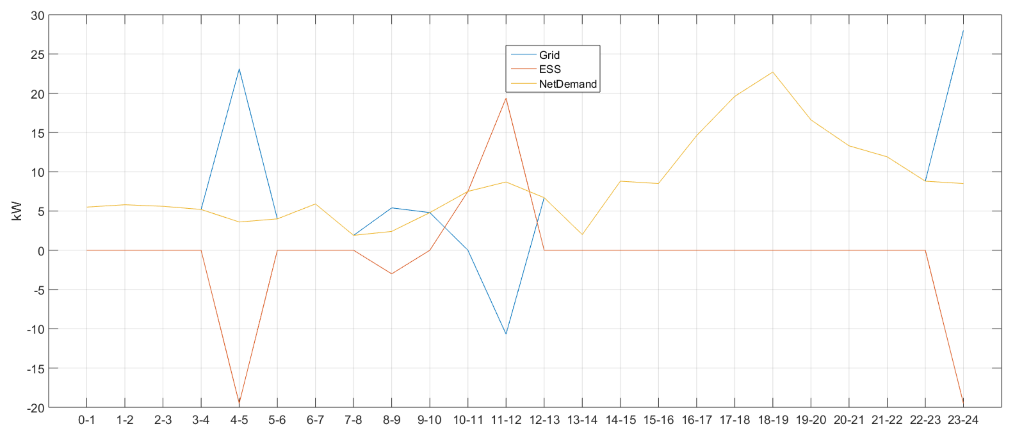
The simulation result from the basic setting is shown in Figure 3, where grid (blue line), ESS (red line) and net demand (yellow line) indicate the system power usage, ESS charging/discharging power and total demand, respectively. Since power demand and supply have to be balanced, the condition net demand-ESS-Grid = 0 must be satisfied. When the grid sign is (+), power is purchased from the system; if the sign is (-), it means that power is sold to the system.
At the same time, the (+) and (−) signs of ESS indicate charging and discharging, respectively. As shown in Figure 4, (n)-(n+1) on the horizontal axis is the time zone for integer n (0–23).
Since the value of ESS in time zones 0–1, 1–2, 2–3 and 3–4 was 0, it can be assumed that there was no charging or discharging in these time zones. Moreover, the overlapping yellow and blue lines satisfy the condition net demand = grid, indicating balanced demand and supply. As the sign of the ESS in time zone 4–5 was (−), it can be assumed that charging was required and that power was bought from the system having a (+) grid sign. There was no ESS charging/discharging in time zones 5–6, 6–7 and 7–8 and power demand and supply were balanced out as the condition net demand = grid was satisfied. The same balance was achieved in time zones 9–10 and 10–11 as the individual grid and ESS signs were (+) and (−), respectively, satisfying the conditions net demand = grid and net demand = ESS, respectively. For the latter time zone, it can be understood that power was discharged from ESS as the sign was (+). The ESS sign in time zone 11–12 was also (+), but the grid sign was (−); this means that power was sold to the system. Meanwhile, there was no ESS charging or discharging in time zones 12–13, 13–14, 14–15, 15–16, 16–17, 17–18, 18–19, 19–20, 20–21, 21–22 and 22–23, indicating that power demand and supply have been balanced; thus satisfying the condition net demand = grid. Lastly, the ESS sign in time zone 23–24 was (−), whereas the grid sign was (+), meaning power was purchased from the system.
Figure 3, where no additional conditions have been applied, shows that the ESS was charged in the time zones having the lowest power unit cost of 66.1 (time zones 4–5, 8–9 and 23–24) but discharged in time zones (10–11 and 11–12) having the highest power unit cost of 111.3.

4. Conditional Equation

4.1. Conditional Equation for Peak Control

The following equation should be added to the objective function when the conditional equation is included:
i P C g , b u y [ c P C , 1 g b u y { 1 + ( c P C , 2 g b u y ) i } d t δ P C g b u y ( i ) + c P C , 3 g b u y d t p P C g b u y ( i ) ]
where c P C , 1 g b u y , c P C , 2 g b u y , c P C , 3 g b u y are the penalty constants for peak control. The possibility of success of peak control will be reflected to the objective function by adding this equation. Likewise, i P g , b u y means that time zone i will be included in the time zones performing peak control. Since the condition δ P C g b u y i = 1 can be satisfied when peak control is successful, the value of objective function will be decreased ( c P C , 1 g b u y { 1 + ( c P C , 2 g b u y ) i } d t 1 ). In such case, the possibility of success of peak control will be largely reflected when the value of c P C , 1 g b u y is large ( c P C , 3 g b u y d t p P C g b u y i = 0 as 0 p P C g b u y i 0 ). In contrast, the value of the objective function will not be decreased when peak control fails ( c P C , 1 g b u y { 1 + ( c P C , 2 g b u y ) i } d t 0 = 0 as δ P C g b u y i = 0 ). This indicates that the value will be increased by c P C , 3 g b u y d t p P C g b u y i as 0 p P C g b u y i . Moreover, the possibility of success of peak control will be highly reflected when the value of c P C , 3 g b u y is large.
Figure 4 shows the result of the simulation to which an external operating condition limiting system power usage to 15 kW in time zone 17–20 has been added to the basic setting (Table 7). The conditional equation for peak control seems to be valid as the system power usages in time zone c P C , 3 g b u y were the same or below 15 kW compared to time zones 17–18, 18–19 and 19–20, where the usages were the same or above 15 kW (note that the blue line indicating system power usage and the yellow line representing total demand are overlapping).
In Figure 4, there was no charging/discharging in time zones 0–1 and 1–2 as the ESS values were 0. In addition, power demand and supply were balanced as net demand = grid was achieved (i.e., overlapping blue and yellow lines). It can be deduced that ESS has been charged as the sign was (−) in time zone 2–3. In this case, the (+) grid sign means that power was purchased from the system. Power demand and supply were balanced (net demand = grid) in time zones 3–4, 4–5, 5–6, 6–7 and 7–8 where there was no charging/discharging activity. The (+) grid sign and (−) ESS sign in time zone 8–9 indicate that power was purchased from the system to charge ESS. Next, no ESS charging/discharging was performed in time zones 9–10, 10–11, 11–12, 12–13, 13–14, 14–15, 15–16 and 16–17 and power demand and supply were balanced, thus satisfying net demand = grid. The same can be said for time zones 20–21, 21–22 and 22–23, but ESS was charged in time zone 23–24 as its sign was (−), buying power from the system.
In Figure 4, where a condition for peak control was included, it can be deduced that ESS was charged in time zones 2–3 and 8–9 due to their low power unit cost (66.1) and discharged in time zones 17–18, 18–19 and 19–20 where the condition was applied to satisfy it.

4.2. Conditional Equation for Power Usage Flattening

The maximum power demand, as well as power charges, can be reduced by improving the quality of power through power usage flattening, the efficiency of new and renewable energy-based generation and the use of off-peak electricity for the peak time hours during the day.
The following equation should be added to the objective function when the conditional equation is included
c g f l a t p g m a x p g m i n T
where c g f l a t is a penalty constant for flattening. When this equation is added, the difference between the maximum and minimum system powers p g m a x p g m i n will be reflected to the objective function. The value of p g m a x p g m i n is reduced to minimize the value of the objective function and system power usage will be flattened. The flattening effect will be largely reflected when the value of c g f l a t becomes larger.
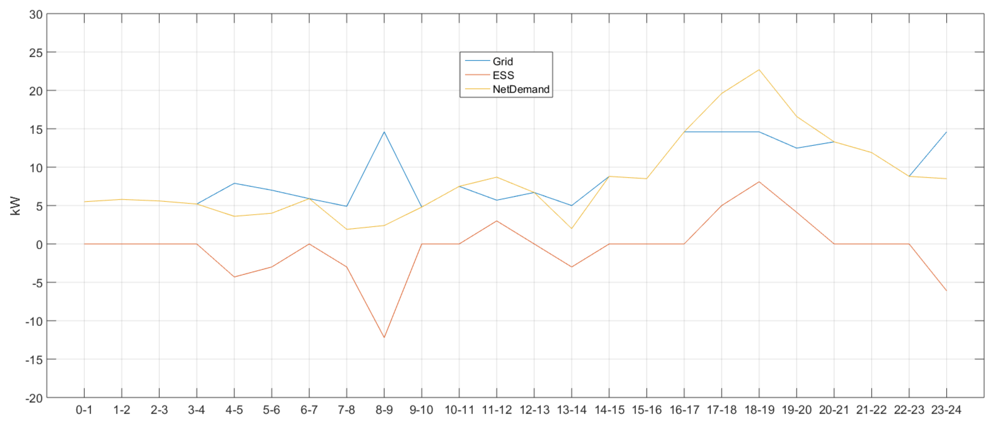
The result of a simulation wherein a flattening condition has been added to the present setting is shown in Figure 5. When comparing it with the simulation result that does not include any conditional equation, as the difference between the maximum and minimum system power usages was reduced from 38.68[ = 28 − (−10.68)] kW to 9.8( = 14.6–4.8) kW, the conditional equation for power flattening can be considered to be valid. The differences were calculated based on the maximum (minimum) values of 28 (−10.68) and 14.6 obtained from time zones 23–24 (11–12) and 8–9, 16–17, 17–18 and 18–19 (9–10), respectively, in Figure 3 and Figure 5.
In Figure 5, the ESS value in time zones 0–1, 1–2, 2–3 and 3–4 was 0, so there was no ESS charging/discharging at all. Moreover, in these zones, power demand and supply were balanced as the condition net demand = grid was satisfied. The ESS signs in time zones 4–5 and 5–6 were (−), so the ESS was charged. At this time, it can be deduced that power had been purchased from the system as the grid sign was (+). There was no ESS charging/discharging in time zone 6–7, so power demand and supply were well-balanced, thus satisfying the same condition. In addition, the (+) sign of the grid and the (−) sign of the ESS in time zones 7–8 and 8–9 showed that power was purchased from the system to charge the ESS. Power demand and supply were balanced in time zones 9–10 and 10–11 so there was no ESS charging/discharging, but demand and supply were balanced as the condition was satisfied. In time zone 11–12, the sign was (+) for both ESS and grid, so power was purchased from the system for charging. There was no ESS charging/discharging in time zone 12–13 and power demand and supply were balanced as the condition was satisfied. Accordingly, the power transactions for charging/discharging activities in each time zone can be grasped by checking the signs or finding out whether the condition has been satisfied or not.
As such, the flattening operations described in Figure 5 showed that the ESS was charged in time zones 4–5, 5–6, 7–8 and 8–9 when the power unit cost was low (66.1) and discharged in time zones 11–12, 17–18, 18–19 and 19–20 when the cost was high (111.3) to consider cost reduction.

4.3. Conditional Equation for Demand Response Power

Demand response is an activity by the electricity users to control their energy usages by shifting themselves from a passive power-user system to an active one, changing their normal power consumption patterns in response to the incentive(s) obtainable by saving power or the differentiated power rates depending on time zones.
The following equation should be added to the objective function when the conditional equation is included:
c D R , 1 { 1 + ( c D R , 2 ) i } δ D R + c D R , 3 P D R
c D R , 1 , c D R , 2 , c D R , 3 are the penalty constants of demand response. The possibility of success of demand response will be reflected to the objective function by adding this equation. When it becomes successful, the value of the objective function will be decreased based on the calculation c D R , 1 { 1 + ( c D R , 2 ) i } d t 1 , δ D R = 1 .
The possibility of success largely depends on the c D R , 1 : c D R , 3 P D R = 0 to be established when c D R , 1 : c D R , 3 P D R = 0 . The value will not decrease when demand response fails ( c D R , 1 { 1 + ( c D R , 2 ) i } d t 0 = 0 , δ D R = 0 ) but will increase instead by c D R , 3 P D R ( 0 P D R ). This suggests that the possibility of failure largely depends on the scale of c D R , 3 .
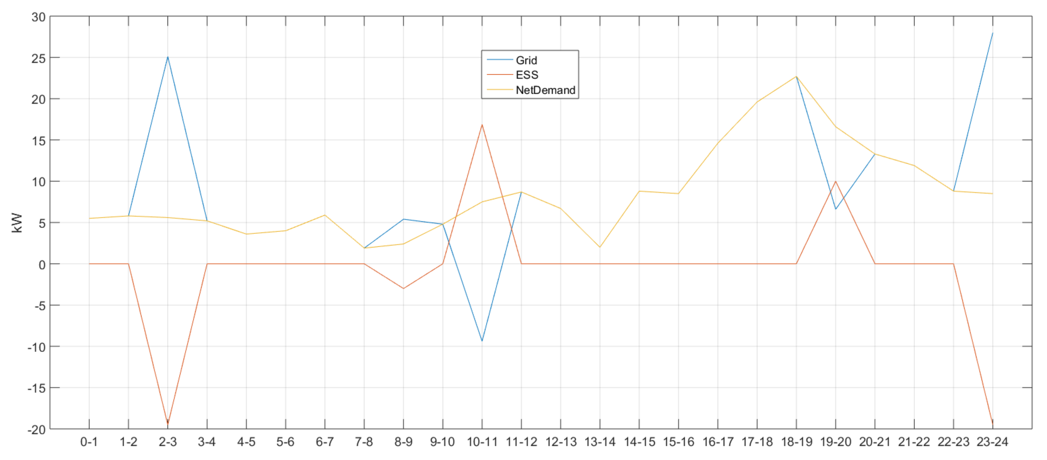
The result of a simulation wherein the external operating condition listed in Table 8 has been added to time zone 17–20 where 10 kW power is to be discharged is shown in Figure 6. By comparing it with the result obtained from the same time zones in Figure 3 where no conditional equations have been included, this conditional equation for demand response can be considered to be valid as the ESS discharging power in time zone 19–20 was 10 kWh (10 kW*1 h).
In Figure 6, there was no ESS charging/discharging in time zones 0–1 and 1–2 as the ESS value was 0. In addition, power demand and supply were balanced as the yellow and blue lines were overlapping (net demand = grid). The (−) ESS sign in time zone 2–3 shows that the ESS had been charged by purchasing power from the system [(+) grid]. Power demand and supply in time zones 3–4, 4–5, 5–6, 6–7 and 7–8 were balanced (net demand = grid) and there was no ESS charging/discharging. Similar to all the other conditions mentioned above, the (+) and (−) signs of either the ESS or the grid explain the power transactions, power balance or ESS charging/discharging events that had taken place.
Added with a demand response condition, Figure 6 also shows that the ESS was charged in time zones 2–3, 8–9 and 23–24 when the power unit cost was low (66.1) and discharged in time zones 10–11 and 19–20 when the cost was high (111.3) to consider cost reduction.

4.4. Conditional Equation for Net Zero Operation

Although achieving net zero energy by utilizing now available new and renewable energy resources or energy-saving equipment is a desirable direction in energy management, establishing a system to realize it can be quite costly.
The following equation should be added to the objective function when the conditional equation is included:
i I O g [ c I O , 1 g { 1 + ( c I O , 2 g ) i } d t δ I O g i + c I O , 3 g d t p I O g i ]
where c I O , 1 g , c I O , 2 g , c I O , 3 g are the penalty constants for peak control. The possibility of success of net zero operation will be reflected to the objective function by adding this equation. In addition, i I O g means that time zone i will be included in the time zones performing the operation. Since the condition δ I O g i = 1 can be satisfied when the operation is successful, the value of the objective function will be decreased ( c I O , 1 g { 1 + ( c I O , 2 g ) i } d t 1 ). In such case, the possibility of success of the operation will be largely reflected when the value of c I O , 1 g is large. In contrast, the value of the objective function will not be decreased when the operation fails ( c I O , 1 g { 1 + ( c I O , 2 g ) i } d t 0 = 0 , δ I O g i = 0 ). This indicates that the value will be increased by c I O , 3 g d t p I O g i as 0 p I O g i . Moreover, the possibility of success of the operation will be highly reflected when the value of c I O , 3 g becomes larger.
The result of a simulation wherein the external operating condition listed in Table 9 has been added to time zone 3–5 for a net zero operation is shown in Figure 7. By comparing it with the result obtained from the same time zones in Figure 3 where system power usage was larger than 0, this conditional equation for the net zero operation can be considered to be valid as the system power usages in time zones 3–4 and 4–5 were 0.

5. Performance Evaluation

Performance evaluations were conducted by comparing a simulation wherein none of the four conditions above had been applied with the simulations to which each of those conditions was applied. For the simulations, MATLAB R2015a was used; the constraints resulting from individual constants and objective functions were used as inputs for the mixed-integer linear programming of MATLAB to show the resultant system power usage, ESS charging/discharging power and total demand with the graphs using a plot function. Thus, for the optimization of microgrid, four environmental conditions have been put to simulations to find the actual conditions that actually have an impact on improving the optimization performance.
Figure 7 shows all power transactions and operations according to the (+) and (−) signs of both the ESS and grid, whereas the overlapping yellow and blue lines indicate successful establishment of the condition net demand = grid. It is possible to understand what had happened in each time zone.
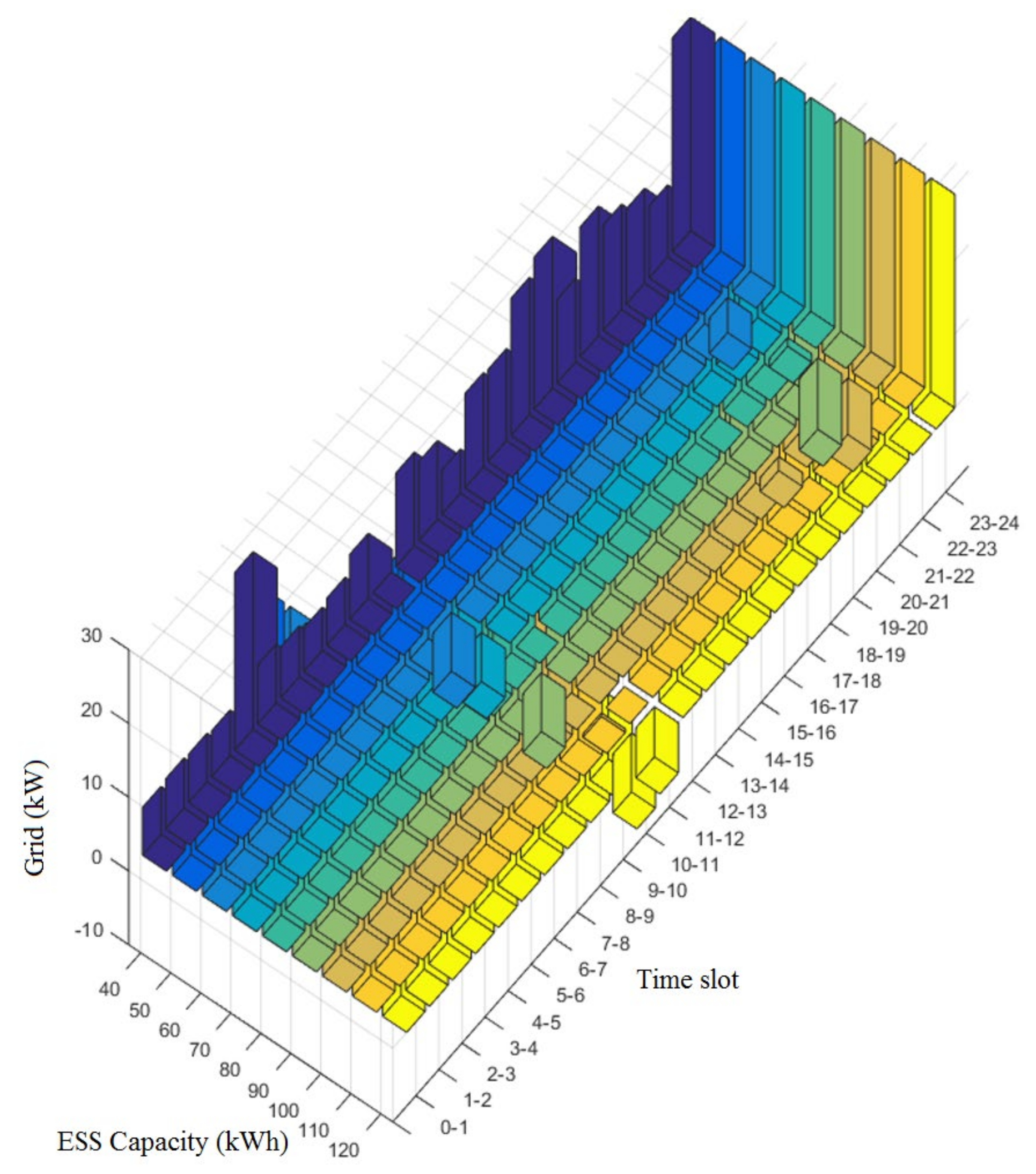
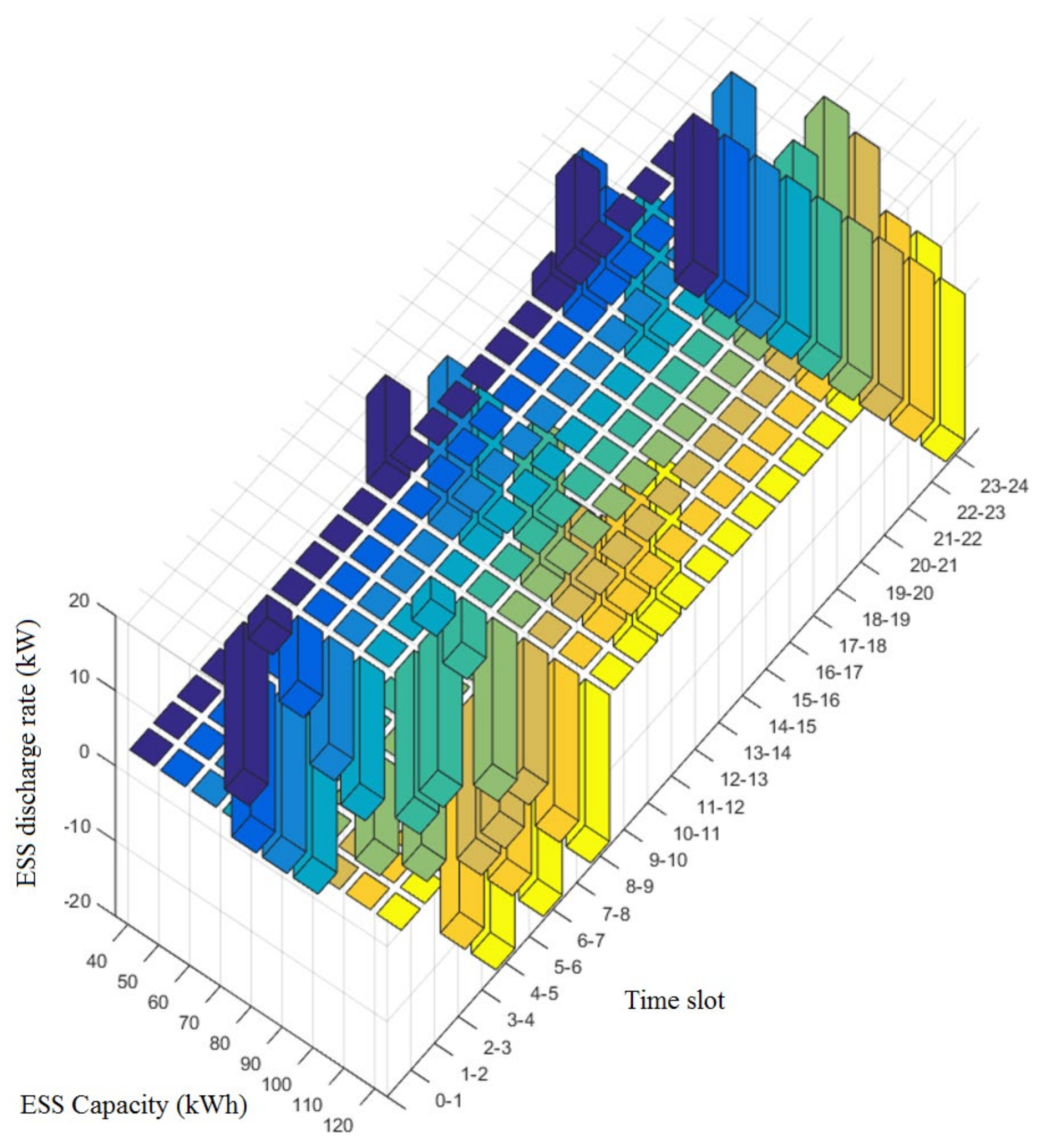
As such, Figure 7 also shows that the ESS was charged in time zones 0–1, 8–9 and 23–24 when the power unit cost was low (66.1) and discharged in time zone 10–11 when the cost was high (111.3) to achieve net zero operation. The system power usages obtained from a simulation conducted by changing the capacity of ESS from 40 to 120 kW (+10 kW per simulation) are shown in Figure 8, Figure 9 and Figure 10 and their discharging powers, in Figure 11, Figure 12 and Figure 13.
Figure 9, Figure 10, Figure 12 and Figure 13 are the pictures of Figure 8 and Figure 11, respectively, when viewed from other angles. The vertical axis in Figure 8, Figure 9 and Figure 10 indicates the system power usages (Grid), whereas the same axis in Figure 11, Figure 12 and Figure 13 is the ESS charging(-)/discharging(-) power. A long axis, “Time Slot,” shows the time zones, with “ESS Capacity” indicating the capacity of the ESS. The bar3 function of MATLAB R2015a was used for graphing.
Observing time zones 4–5 and 8–9 in Figure 8, Figure 9 and Figure 10, it is possible to recognize the tendency of increasing system power usages in proportion to the ESS capacity. This would mean that the grid is pursuing an economic gain by charging its ESS when the power unit cost is low and selling or reducing its purchase during the time zones when the cost is high.
The time zones where power unit cost is at the lowest or highest level are 9–10 and 12–17. Observing these time zones in Figure 11, Figure 12 and Figure 13, there were no charging/discharging operations. This also proves that the grid is considering gaining profit by discharging its ESS when the power unit cost is highest and vice versa.
Being a local power grid, a Micro Grid consists of a series of DERs along with loads and is self-sustainable or runs with the existing power grid. In such a power grid, the system operator/administrator managing the entire supply and consumption of these resources assigns some of his/her sublevel tasks to individual operators under him/her. The passive production resources are often affected by the natural environments beyond the control of operators such as weather. A series of simulations were conducted in this study for evaluation to optimize the efficiency of the Micro Grid. Each one of the four conditional expressions (i.e., peak-zero, power-use flattening, demand-response and net zero operation) was applied to the simulations to compare with the case where none of these expressions were applied. Each performance was evaluated, and the validity of the expressions was determined through simulations which proved their effectiveness for the optimization of Micro Grids as a result.

6. Conclusions

This study conducted simulations for cases wherein none of the four kinds of conditional equations (i.e., conditional equations for peak control, power use flattening, power demand response and operation of net zero Energy) or at least one of them had been applied to compare them and evaluate the effectiveness of each equation. The result showed that the conditional equations were found to be effective when attempting to optimize the microgrid’s performance efficiently.
The peak-control conditional equation was found to be effective in the simulation as system power usage was decreased below the peak level set at 15 kW. ESS was charged during the daytime when the power cost was low and discharged in the time zones when peak control was implemented.
In the simulation applied with the conditional equation for flattening power use, this equation was found to be effective as the difference between the maximum and minimum system power usages was decreased from 38.68 kW to 9.8 kW. ESS charging was carried out during the daytime when the power cost was low, whereas discharging was performed in the time zones when it was high.
In the simulation applied with the conditional equation for power demand-response, the equation was found to be effective as the power set to be discharged (10 kW) in a fixed time zone was achieved successfully. In this case, ESS was charged during the daytime when the power cost was low.
In the simulation applied with the conditional equation for net zero energy operation, the equation was found to be effective as the system power usage became 0 in a designated time zone, despite the fact that the power cost in that time zone (daytime) was low. As for the rest of the time zones, ESS charging was performed during the daytime, but discharging was carried out in the time zones when the power cost was high.
The results above showed that all the equations were effective in every case and it can be confirmed that all the ESS operating schedules, except net zero energy operation, had been adjusted in such a way that power is charged during the daytime and discharged or sold when the power cost was highest.

Author Contributions

Conceptualization, S.J.; Data curation, S.J.; Formal analysis, S.J.; Funding acquisition, J.-H.H.; Methodology, S.J. and Y.T.Y.; Project administration, S.J., Y.T.Y. and J.-H.H.; Resources, Y.T.Y. and J.-H.H.; Software, S.J.; Supervision, Y.T.Y. and J.-H.H.; Visualization, S.J. and Y.T.Y.; Writing—original draft, S.J. and J.-H.H.; Writing—review & editing, Y.T.Y. and J.-H.H. All authors have read and agreed to the published version of the manuscript.

Funding

This work was supported by the National Research Foundation of Korea (NRF) Grant funded by the Korean Government (MSIT) (No.2017R1C1B5077157). Also, this research was supported by the Energy Cloud R&D Program through the National Research Foundation of Korea (NRF) funded by the Ministry of Science, ICT (NRF-2019M3F2A1073385).

Conflicts of Interest

The authors declare no conflict of interest.

Abbreviations

DERsdistributed energy resources
DRdemand response
EMSenergy management system
PVphotovoltaic
ESSenergy storage system
WTwind turbine
SoCstate of charge

References

  1. Huh, J.-H. Smart Grid Test Bed Using OPNET and Power Line Communication; IGI Global: Hershey, PA, USA, 2017; pp. 1–425. [Google Scholar]
  2. Mun, J.H.; Ko, J.S.; Choi, J.S.; Jang, M.G.; Chung, D.H. Efficiency optimization control of SynRM drive using multi-AFLC. In Proceedings of the 2010 International Conference on Electrical Machines and Systems, Incheon, Korea, 11–13 October 2010; IEEE: New York, NY, USA, 2010; pp. 908–913. [Google Scholar]
  3. Choi, J.S.; Ko, J.-S.; Chung, D.-H. Efficiency Analysis of PV tracking system with PSA Algorithm. J. Korean Inst. Illum. Electr. Install. Eng. 2009, 23, 36–44. [Google Scholar]
  4. Park, D.-M.; Kim, S.-K.; Seo, Y.-S. S-mote: SMART Home Framework for Common Household Appliances in IoT Network. J. Inf. Process. Syst. KIPS 2019, 15, 449–456. [Google Scholar]
  5. Arcos-Aviles, D.; Pascual, J.; Marroyo, L.; Sanchis, P.; Guinjoan, F. Fuzzy logic-based energy management system design for residential grid-connected microgrids. IEEE Trans. Smart Grid 2016, 9, 530–543. [Google Scholar] [CrossRef]
  6. Zhang, W.; Ma, Y.; Liu, W.; Ranade, S.J.; Luo, Y. Distributed optimal active power dispatch under constraints for smart grids. IEEE Trans. Ind. Electron. 2016, 64, 5084–5094. [Google Scholar] [CrossRef]
  7. Gamarra, C.; Guerrero, J.M. Computational optimization techniques applied to microgrids planning: A review. Renew. Sustain. Energy Rev. 2015, 48, 413–424. [Google Scholar] [CrossRef] [Green Version]
  8. Kim, H.; Kinoshita, T. A new challenge of microgrid operation. Commun. Comput. Inf. Sci. 2010, 78, 250–260. [Google Scholar]
  9. Mohanpurkar, M.; Ouroua, A.; Hovsapian, R.; Luo, Y.; Singh, M.; Muljadi, E.; Gevorgian, V.; Donalek, P. Real-time co-simulation of adjustable-speed pumped storage hydro for transient stability analysis. Electr. Power Syst. Res. 2018, 154, 276–286. [Google Scholar] [CrossRef]
  10. Chen, J.; Yang, X.; Zhu, L.; Zhang, M.; Li, Z. Microgrid multi-objective economic dispatch optimization. Proc. CSEE 2013, 33, 57–66. [Google Scholar]
  11. Saad, W.; Han, Z.; Poor, H.V.; Basar, T. Game-theoretic methods for the smart grid: An overview of microgrid systems, demand-side management, and smart grid communications. IEEE Signal Process. Mag. 2012, 29, 86–105. [Google Scholar] [CrossRef]
  12. Khan, M.; Basir, R.; Jidin, R.; Pasupuleti, J. Multi-agent based distributed control architecture for microgrid energy management and optimization. Energy Convers. Manag. 2016, 112, 288–307. [Google Scholar] [CrossRef]
  13. Hori, H.; Ishigaki, Y.; Kimura, Y.; Mai, T.X.; Ozaki, T.; Yokose, T. Energy management system (sEMSA) achieving energy cost minimization. SEI Tech. Rev. 2015, 81, 56–62. Available online: https://global-sei.com/technology/tr/bn81/pdf/81-11.pdf (accessed on 20 September 2018).
  14. Huh, J.-H.; Seo, K. Hybrid AMI design for Smart Grid using the Game Theory model. Adv. Sci. Technol. Lett. 2015, 108, 86–92. [Google Scholar]
  15. Zhang, Y.; Zhang, T.; Wang, R.; Liu, Y.; Guo, B. Optimal operation of a smart residential microgrid based on model predictive control by considering uncertainties and storage impacts. Sol. Energy 2015, 122, 1052–1065. [Google Scholar] [CrossRef]
  16. Li, J.; Chung, J.Y.; Xiao, J.; Hong, J.W.-K.; Boutaba, R. On the design and implementation of a home energy management system. In Proceedings of the International Symposium on Wireless and Pervasive Computing, Hong Kong, China, 23–25 February 2011; pp. 1–6. [Google Scholar]
  17. Al-Ali, A.; El-Hag, A.; Bahadiri, M.; Harbaji, M.; El Haj, Y.A. Smart Home Renewable Energy Management System. Energy Procedia 2011, 12, 120–126. [Google Scholar] [CrossRef] [Green Version]
  18. Zhang, Y.; Zeng, P.; Li, S.; Zang, C.; Li, H. A Novel Multiobjective Optimization Algorithm for Home Energy Management System in Smart Grid. Math. Probl. Eng. 2015, 2015, 1–19. [Google Scholar] [CrossRef] [Green Version]
  19. Rodriguez, D.I.H.; Braun, M. A comparative study of optimization-and rule-based control for microgrid operation. In Proceedings of the Power and Energy Student Summit (PESS), Dortmund, Germany, 13–14 January 2015. [Google Scholar]
  20. Luna, A.C.; Diaz, N.L.; Graells, M.; Vasquez, J.C.; Guerrero, J.M.; Aldana, N.L.D. Mixed-Integer-Linear-Programming-Based Energy Management System for Hybrid PV-Wind-Battery Microgrids: Modeling, Design, and Experimental Verification. IEEE Trans. Power Electron. 2016, 32, 2769–2783. [Google Scholar] [CrossRef] [Green Version]
  21. Li, H.; Eseye, A.T.; Zhang, J.; Zheng, D. Optimal energy management for industrial microgrids with high-penetration renewables. Prot. Control Mod. Power Syst. 2017, 2, 12. [Google Scholar] [CrossRef] [Green Version]
  22. Ju, C.; Wang, P.; Goel, L.; Xu, Y. A Two-Layer Energy Management System for Microgrids with Hybrid Energy Storage Considering Degradation Costs. IEEE Trans. Smart Grid 2017, 9, 6047–6057. [Google Scholar] [CrossRef]
  23. Mohamed, F.A.; Koivo, H.N. System modelling and online optimal management of microgrid with battery storage. Renew. Energy Power Qual. J. 2007, 1, 74–78. [Google Scholar] [CrossRef]
  24. Mohamed, F.A.; Koivo, H.N. Online Management of MicroGrid with Battery Storage Using Multiobjective Optimization. In Proceedings of the 2007 International Conference on Power Engineering, Energy and Electrical Drives, Setubal, Portugal, 12–14 April 2007; pp. 231–236. [Google Scholar]
  25. Parisio, A.; Glielmo, L. Energy efficient microgrid management using model predictive control. In Proceedings of the 50th IEEE Conference on Decision and Control and European Control Conference, Orlando, FL, USA, 12–15 December 2011; pp. 5449–5454. [Google Scholar]
  26. Malysz, P.; Sirouspour, S.; Emadi, A. An Optimal Energy Storage Control Strategy for Grid-connected Microgrids. IEEE Trans. Smart Grid 2014, 5, 1785–1796. [Google Scholar] [CrossRef]
  27. Shi, W.; Xie, X.; Chu, C.-C.; Gadh, R. Distributed Optimal Energy Management in Microgrids. IEEE Trans. Smart Grid 2014, 6, 1137–1146. [Google Scholar] [CrossRef]
  28. Hoffmann, K.; Menzel, K. A Guideline for the Implementation of an Energy Management System in Facility Management Organisations. Appl. Mech. Mater. 2019, 887, 247–254. [Google Scholar] [CrossRef]
  29. Zhai, S.; Wang, Z.; Yan, X.; He, G. Appliance Flexibility Analysis Considering User Behavior in Home Energy Management System Using Smart Plugs. IEEE Trans. Ind. Electron. 2018, 66, 1391–1401. [Google Scholar] [CrossRef]
  30. Eissa, M. Developing incentive demand response with commercial energy management system (CEMS) based on diffusion model, smart meters and new communication protocol. Appl. Energy 2019, 236, 273–292. [Google Scholar] [CrossRef]
  31. Nge, C.L.; Ranaweera, I.U.; Midtgård, O.-M.; Norum, L. A real-time energy management system for smart grid integrated photovoltaic generation with battery storage. Renew. Energy 2019, 130, 774–785. [Google Scholar] [CrossRef] [Green Version]
  32. Gazafroudi, A.S.; Soares, J.; Ghazvini, M.A.F.; Pinto, T.; Vale, Z.; Corchado, J.M. Stochastic interval-based optimal offering model for residential energy management systems by household owners. Int. J. Electr. Power Energy Syst. 2019, 105, 201–219. [Google Scholar] [CrossRef]
  33. Alasali, F.; Haben, S.; Holderbaum, W. Energy management systems for a network of electrified cranes with energy storage. Int. J. Electr. Power Energy Syst. 2019, 106, 210–222. [Google Scholar] [CrossRef]
  34. Chapaloglou, S.; Nesiadis, A.; Iliadis, P.; Atsonios, K.; Nikolopoulos, N.; Grammelis, P.; Yiakopoulos, C.; Antoniadis, I.; Kakaras, E. Smart energy management algorithm for load smoothing and peak shaving based on load forecasting of an island’s power system. Appl. Energy 2019, 238, 627–642. [Google Scholar] [CrossRef]
  35. Lopez, J.M.G.; Pouresmaeil, E.; Canizares, C.A.; Bhattacharya, K.; Mosaddegh, A.; Solanki, B.V.; Gonzalez, J.M.; Solanki, B. Smart Residential Load Simulator for Energy Management in Smart Grids. IEEE Trans. Ind. Electron. 2018, 66, 1443–1452. [Google Scholar] [CrossRef] [Green Version]
  36. Wang, Y.; Sun, Z.; Chen, Z. Rule-based energy management strategy of a lithium-ion battery, supercapacitor and PEM fuel cell system. Energy Procedia 2019, 158, 2555–2560. [Google Scholar] [CrossRef]
  37. Farmani, F.; Parvizimosaed, M.; Monsef, H.; Rahimi-Kian, A. A conceptual model of a smart energy management system for a residential building equipped with CCHP system. Int. J. Electr. Power Energy Syst. 2018, 95, 523–536. [Google Scholar] [CrossRef]
  38. Wang, F.; Zhou, L.; Ren, H.; Liu, X.; Talari, S.; Shafie-Khah, M.; Catalao, J.P.S. Multi-Objective Optimization Model of Source–Load–Storage Synergetic Dispatch for a Building Energy Management System Based on TOU Price Demand Response. IEEE Trans. Ind. Appl. 2018, 54, 1017–1028. [Google Scholar] [CrossRef]
  39. Thomas, D.; Deblecker, O.; Ioakimidis, C.S. Optimal operation of an energy management system for a grid-connected smart building considering photovoltaics’ uncertainty and stochastic electric vehicles’ driving schedule. Appl. Energy 2018, 210, 1188–1206. [Google Scholar] [CrossRef]
  40. Van Der Meer, D.; Mouli, G.R.C.; Mouli, G.M.-E.; Elizondo, L.R.; Bauer, P.; Morales-Espana, G. Energy Management System with PV Power Forecast to Optimally Charge EVs at the Workplace. IEEE Trans. Ind. Inform. 2016, 14, 311–320. [Google Scholar] [CrossRef] [Green Version]
  41. Nunna, H.S.V.S.K.; Battula, S.; Doolla, S.; Srinivasan, D. Energy Management in Smart Distribution Systems with Vehicle-to-Grid Integrated Microgrids. IEEE Trans. Smart Grid 2016, 9, 4004–4016. [Google Scholar] [CrossRef]
  42. Azizivahed, A.; Naderi, E.; Narimani, H.; Fathi, M.; Narimani, M.R. A New Bi-Objective Approach to Energy Management in Distribution Networks with Energy Storage Systems. IEEE Trans. Sustain. Energy 2017, 9, 56–64. [Google Scholar] [CrossRef]
  43. Indragandhi, V.; Logesh, R.; Subramaniyaswamy, V.; Vijayakumar, V.; Siarry, P.; Uden, L. Multi-objective optimization and energy management in renewable based AC/DC microgrid. Comput. Electr. Eng. 2018, 70, 179–198. [Google Scholar]
  44. Pilloni, V.; Floris, A.; Meloni, A.; Atzori, L. Smart Home Energy Management Including Renewable Sources: A QoE-driven Approach. IEEE Trans. Smart Grid 2016, 9, 2006–2018. [Google Scholar] [CrossRef] [Green Version]
  45. Ali, I.; Hussain, S.M.S. Communication Design for Energy Management Automation in Microgrid. IEEE Trans. Smart Grid 2016, 9, 2055–2064. [Google Scholar] [CrossRef]
  46. Ma, W.-J.; Wang, J.; Gupta, V.; Chen, C. Distributed Energy Management for Networked Microgrids Using Online ADMM With Regret. IEEE Trans. Smart Grid 2018, 9, 847–856. [Google Scholar] [CrossRef]
  47. Lee, S.Y.; Jin, Y.G.; Yoon, Y.T. Determining the Optimal Reserve Capacity in a Microgrid with Islanded Operation. IEEE Trans. Power Syst. 2016, 31, 1369–1376. [Google Scholar] [CrossRef]
  48. Eom, S.; Huh, J.-H. The Opening Capability for Security against Privacy Infringements in the Smart Grid Environment. Mathematics 2018, 6, 202. [Google Scholar] [CrossRef] [Green Version]
  49. Jung, S.; Huh, J.-H. Demand Response Resource Energy Optimization System for Residential Buildings: Smart Grid Approach. In Advanced Multimedia and Ubiquitous Engineering; Springer: Berlin/Heidelberg, Germany, 2018; pp. 517–522. [Google Scholar]
Figure 1. System diagram (red arrow: supply of power; blue arrow: flow of information).
Mathematics 08 00560 g001
Figure 2. Diagram showing the changes in system power usages, ESS charging/discharging according to the external operating conditions.
Mathematics 08 00560 g002
Figure 3. Simulation result when there were no special conditional equations included.
Mathematics 08 00560 g003
Figure 4. Simulation result when the conditional equation for peak control was included.
Mathematics 08 00560 g004
Figure 5. Simulation result when the conditional equation for system power flattening (power use) was included.
Mathematics 08 00560 g005
Figure 6. Simulation result when the conditional equation for demand response (power usage) was included.
Mathematics 08 00560 g006
Figure 7. Simulation result when the conditional equation for net zero operation was included.
Mathematics 08 00560 g007
Figure 8. System power usage by ESS capacity (1).
Mathematics 08 00560 g008
Figure 9. System power usage by ESS capacity (2).
Mathematics 08 00560 g009
Figure 10. System power usage by ESS capacity (3).
Mathematics 08 00560 g010
Figure 11. Discharging power by ESS capacity (1).
Mathematics 08 00560 g011
Figure 12. Discharging power by ESS capacity (2).
Mathematics 08 00560 g012
Figure 13. Discharging power by ESS capacity (3).
Mathematics 08 00560 g013
Table 1. Definitions of Variables (1).
VariablesDefinitions
P P V k Power (kW) obtained with new and renewable energy generation in time zone k
P P V ,   E S S k Power (kW) transmitted from PV to ESS in time zone k
P P V ,   L o a d k Power (kW) transmitted from PV to load in time zone k
E E S S k Amount of power (kWh) stored in time zone k
P E S S d i s k Power (kW) discharged in time zone k
P E S S , L o a d d i s k Power (kW) transmitted from ESS to load in time zone k
P E S S , g d i s k Power (kW) transmitted from ESS to power grid in time zone k
P E S S c h g k Power (kW) charged to ESS in time zone k
P g , 1 k Power (kW) received from power grid in time zone k
P g , E S S k Power (kW) transmitted from power grid to ESS in time zone k
P g , L o a d k Power (kW) transmitted from power grid to load in time zone k
P g , 2 k Power (kW) transmitted from power grid to in time zone k
P L o a d k Power (kW) consumed by load in time zone k
Table 2. Definitions of Variables (2).
VariablesDefinitions
d P V k PV data in time zone k
d L o a d k Load data in time zone k
D P V k = d P V 1 , d P V 2 , , d P V k 1 PV data set in time zone 1–(k-1)
D L o a d k = d L o a d 1 , d L o a d 2 , , d L o a d k 1 Load data set in time zone 1–(k-1)
D k = D P V k D L o a d k Data storage in time zone k
f p r d , P V Function (or algorithm) to predict PV
f p r d , L o a d Function (or algorithm) to predict load
P V p r d k PV value calculated based on PV prediction in time zone k
V p r d k , n : D P V k n PV data predicted based on D_PV [k]
L o a d p r d k Load value calculated based on load prediction in time zone k
L o a d p r d k , n : D L o a d k n load data predicted based on D L o a d k
C Set of constants
I c o s t Power unit price info
I e x t External operating conditions info
I s p e c ESS performance info
I e x t Other constants including SoC range setting in each time zone, etc.
f Objective function coefficient vector
M Set of matrices or vectors representing constraints
f o Function (or algorithm) for the calculation of optimal solutions
x ESS operation schedule
Table 3. Basic setting for the simulation.
Range of ESS Charging PowerRange of ESS Discharging PowerSoC by Time ZoneESS Capacity
3–19.5 kW3–19.5 kW0.05–0.9540 kWh
Table 4. Forecast prices of power demand schedule (virtual data) (kW).
Time Zone0–11–22–33–44–55–66–77–88–99–1010–1111–12
Demand
(kW)
5.55.85.65.23.645.97.911.416.825.526.7
Time Zone12–1313–1414–1515–1616–1717–1818–1919–2020–2121–2222–2323–24
Demand
(kW)
24.72323.823.523.624.622.716.613.311.98.88.5
Table 5. Forecast prices of power supply schedule (virtual data) (kW).
Time Zone0–11–22–33–44–55–66–77–88–99–1010–1111–12
Supply
(kW)
000000069121818
Time Zone12–1313–1414–1515–1616–1717–1818–1919–2020–2121–2222–2323–24
Supply
(kW)
1821151596000000
Table 6. Power unit price schedule (virtual data) (Korean won/kWh).
Time Zone0–11–22–33–44–55–66–77–88–99–1010–1111–12
Unit Price for Purchase66.166.166.166.166.166.166.166.166.196.5111.3111.3
Unit Price for Sales66.166.166.166.166.166.166.166.166.196.5111.3111.3
Time Zone12–1313–1414–1515–1616–1717–1818–1919–2020–2121–2222–2323–24
Unit Price for Purchase96.596.596.596.596.5111.3111.3111.396.596.5111.366.1
Unit Price for Sales96.596.596.596.596.5111.3111.3111.396.596.5111.366.1
Table 7. Peak control operating condition.
Time ZonePeak Setting
Condition17–18, 18–19, 19–2015 kW
Table 8. Demand response operating condition.
-Time ZoneDemand Response Setting
Condition17–18, 18–19, 19–2010 kWh
Table 9. Net Zero operating condition.
-Time Zone
Condition3–4, 4–5