Computation of Analytical Zoom Locus Using Padé Approximation


Abstract
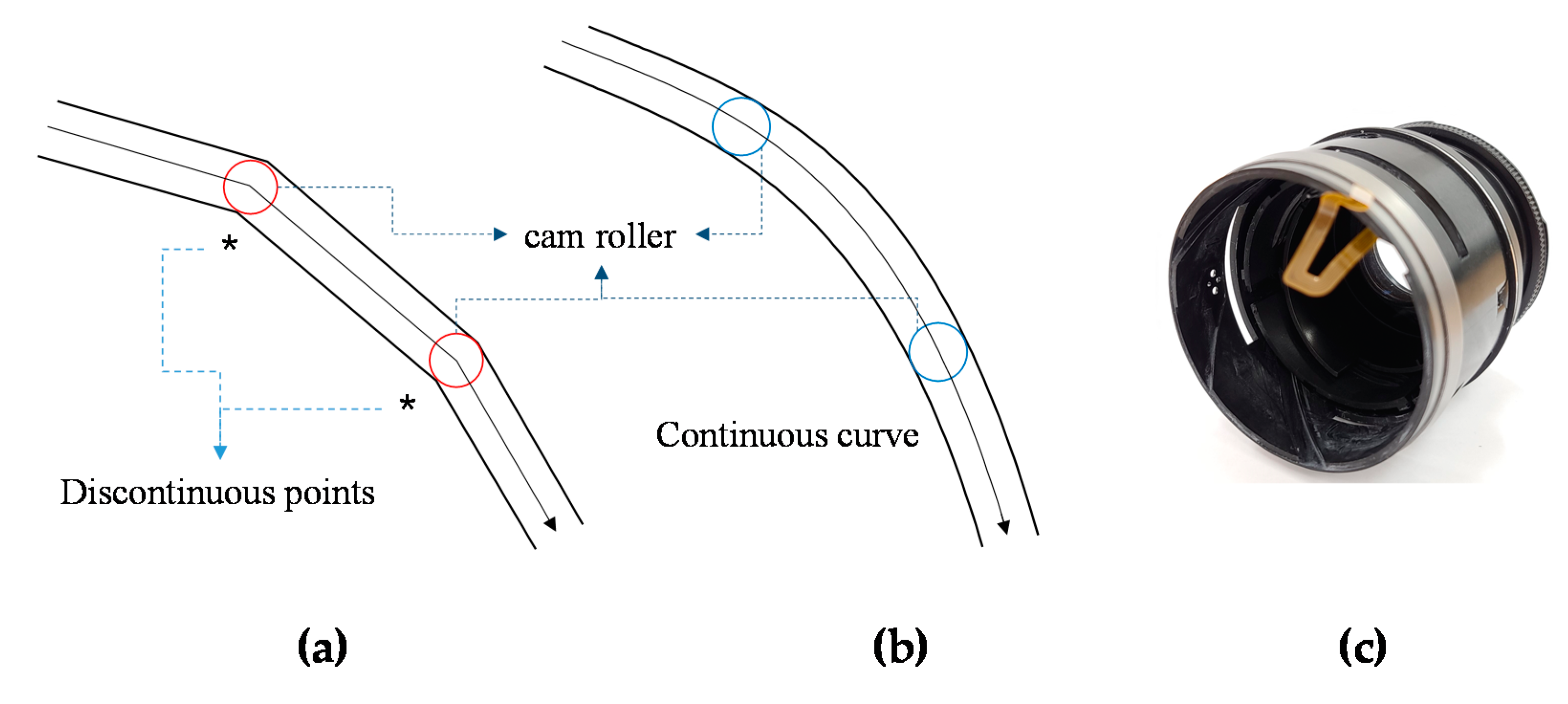
:1. Introduction
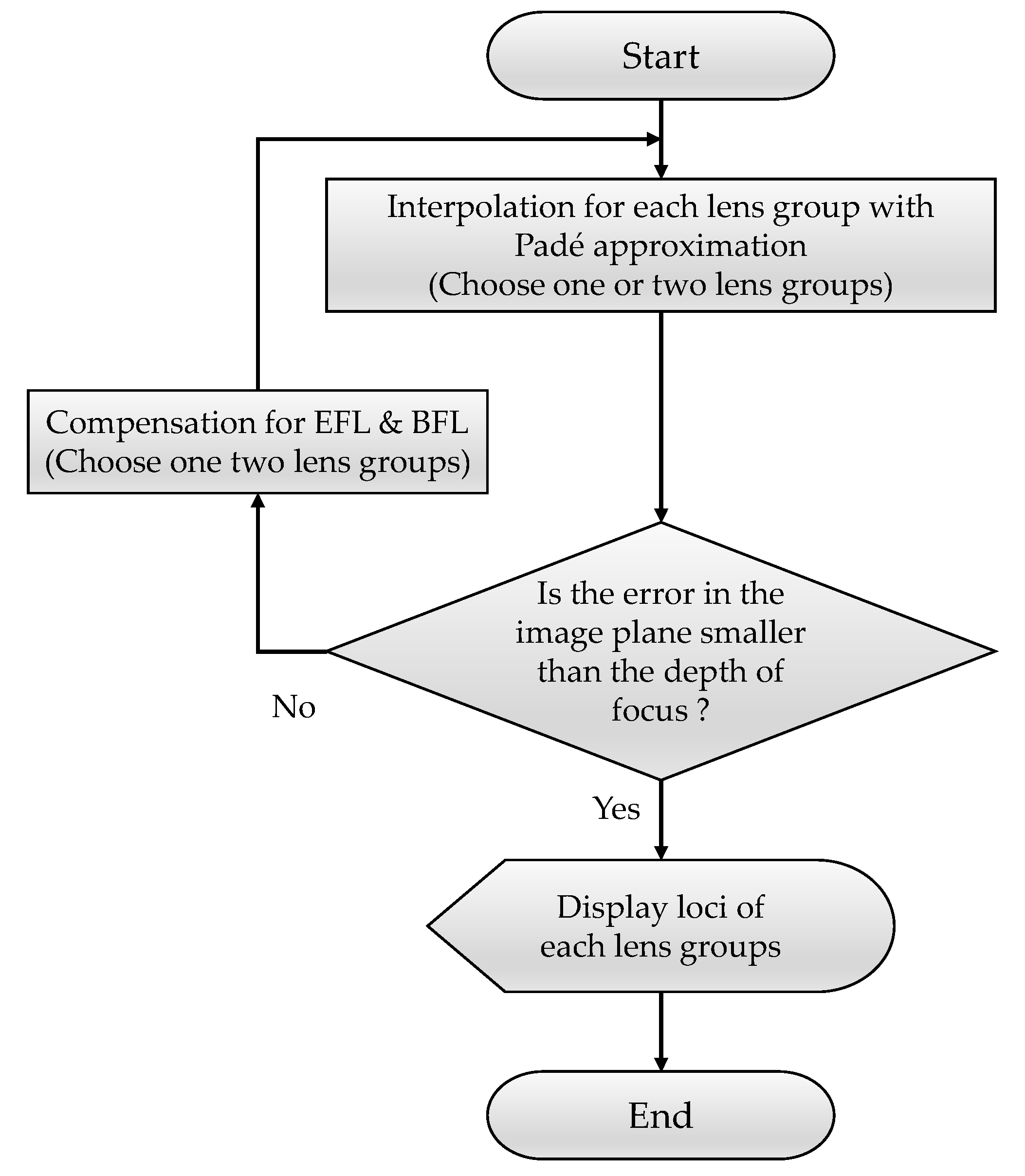
2. Materials and Methods
| Algorithm 1: MATLAB code for Padé approximation |
| 1: function (): PadeApproximation(f,f0,x,x0,n) 2: X = x-x0 3: df = (f-f0)./X 4: A = zeros(2*n,2*n) 5: for i = 1:n-1 6: A(:,i) = X.^(n-i) 7: A(:,n+i) = -f.*(X.^(n-i)) 8: end 9: A(:,n) = ones(2*n,1) 10: A(:,2*n) = -f 11: B = A\df 12: a = B(1:n,:) 13: b = B((n+1):2*n,:) |
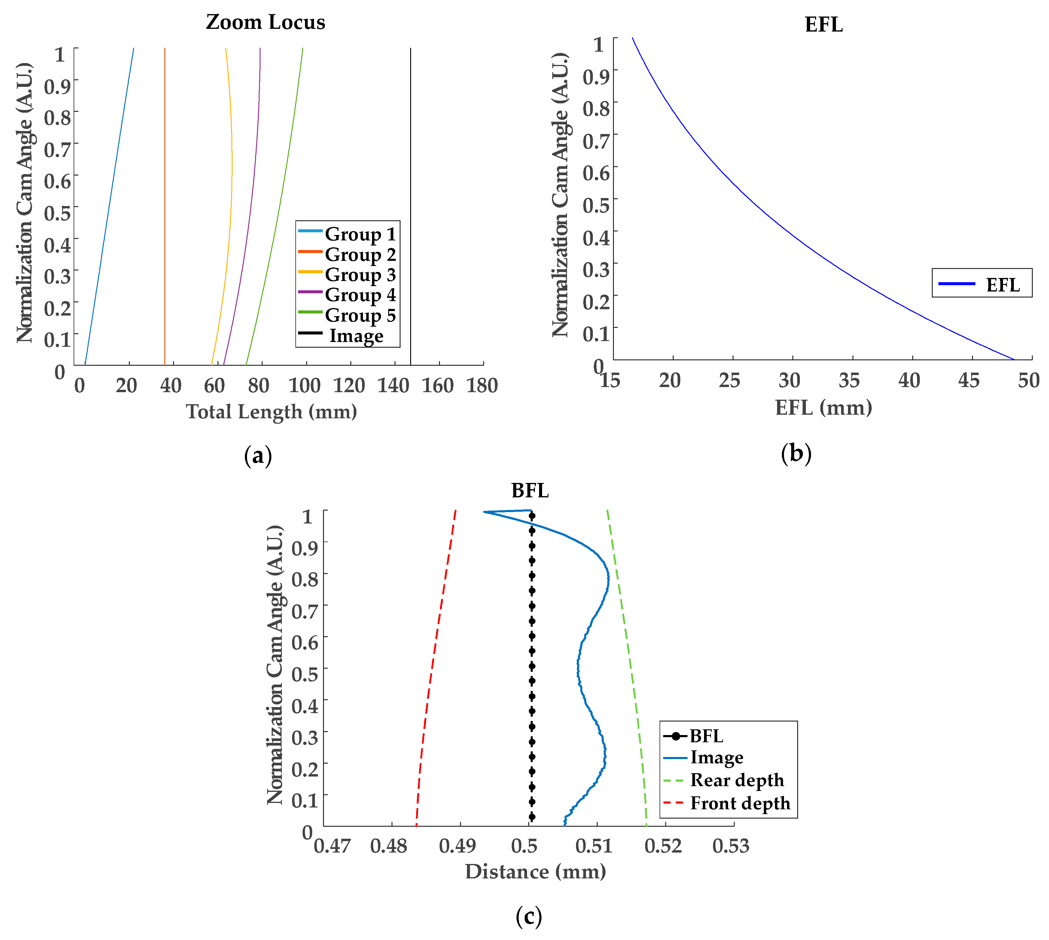
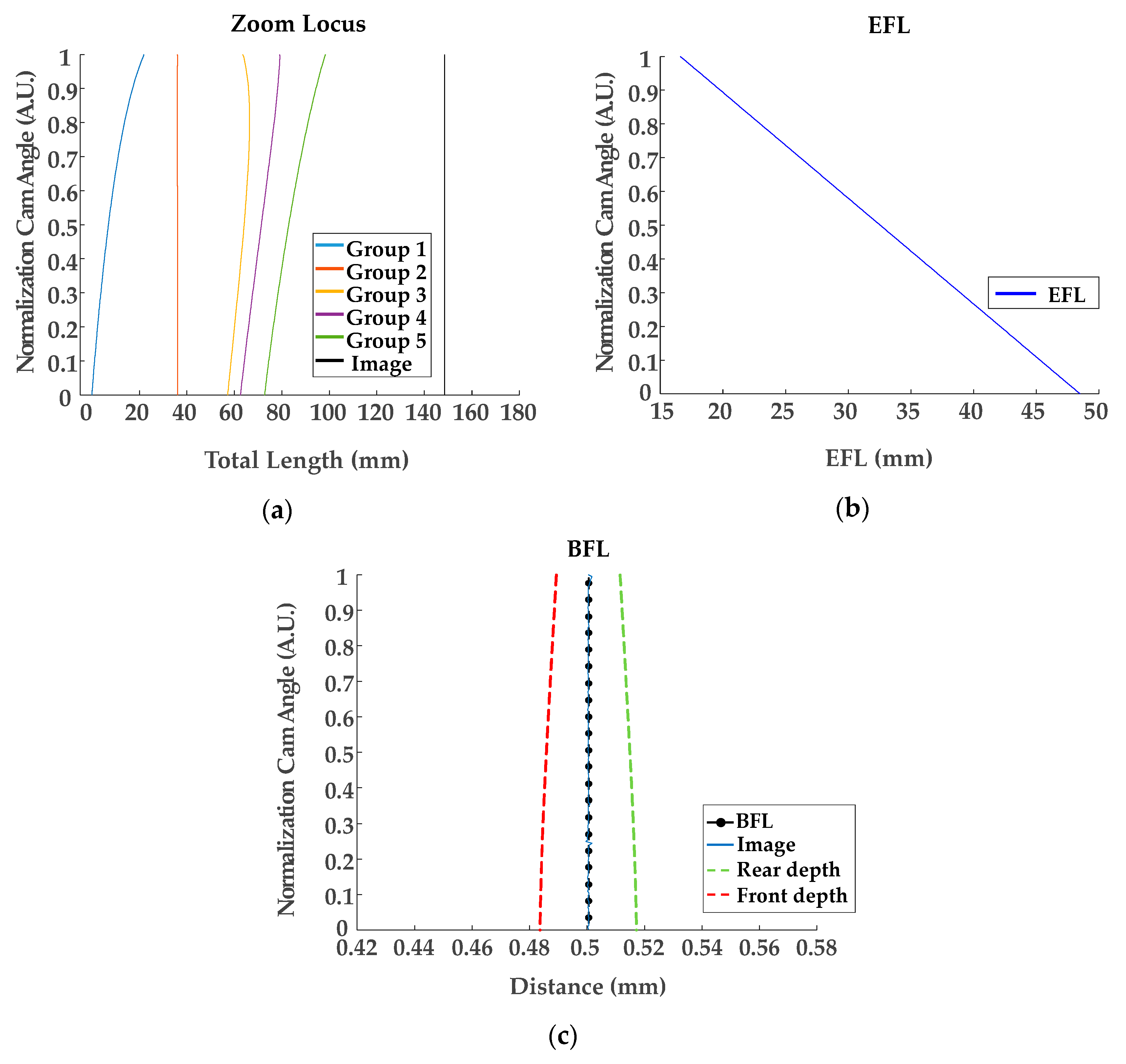
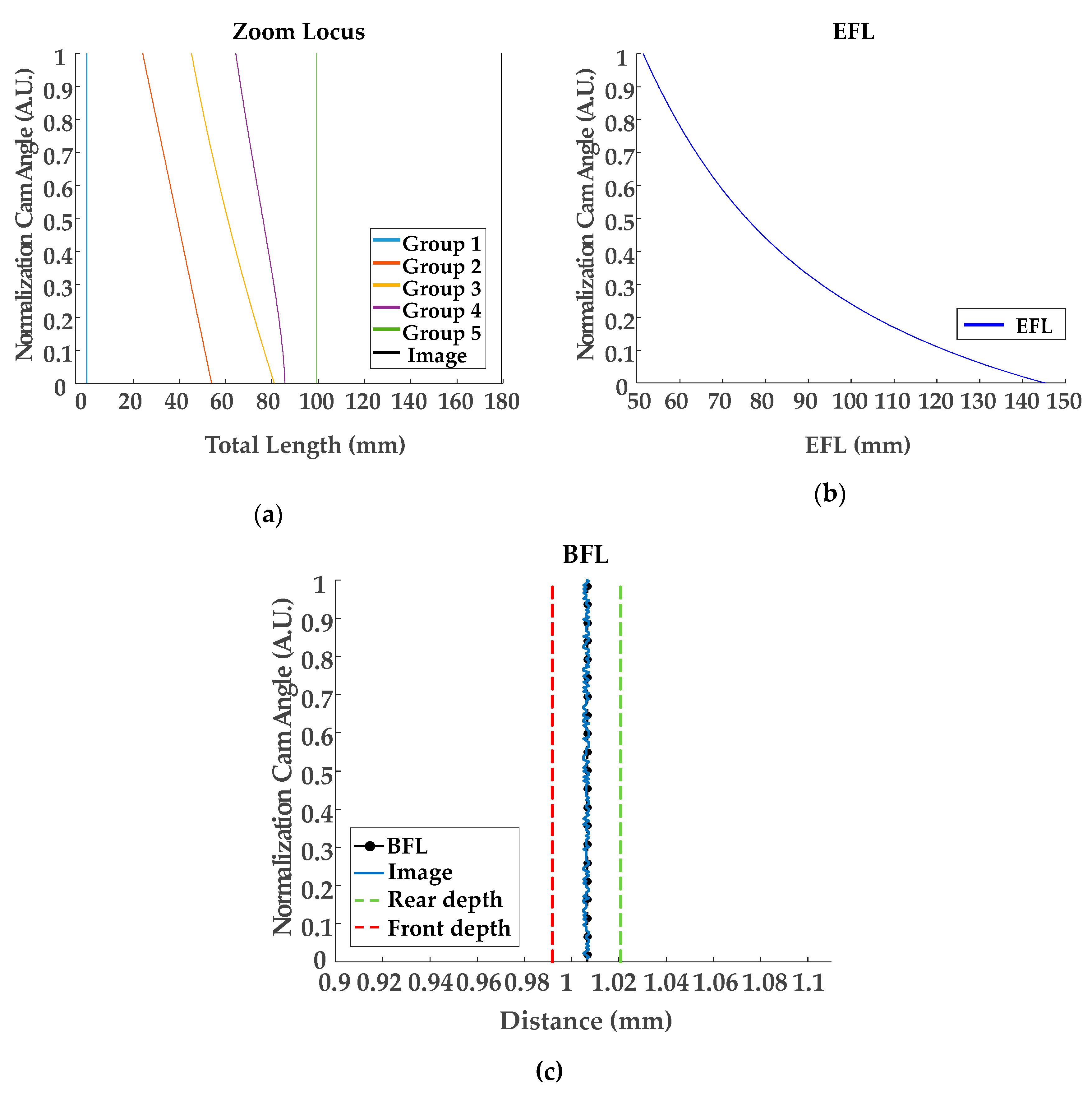
3. Results and Discussion
4. Conclusions
Author Contributions
Funding
Acknowledgments
Conflicts of Interest
Appendix A. Description for MATLAB Code for Padé Approximation
| Algorithm A1: MATLAB code description |
| 1: function (): PadeApproximation(f,f0,x,x0,n) 2: X = x-x0 % calculate initial values for cam angle 3: df = (f-f0)./X % calculate the right side of Equation (22) 4: A = zeros(2*n,2*n) % Initialization for matrix A at Equation (22) 5: % Calculation of matrix A 6: for i = 1:n-1 7: A(:,i) = X.^(n-i) 8: A(:,n+i) = -f.*(X.^(n-i)) 9: end 10: A(:,n) = ones(2*n,1) 11: A(:,2*n) = -f 12: B = A\df % Calculation of Equation (22) 13: a = B(1:n,:) % Polynomial coefficients for the denominator 14: b = B((n+1):2*n,:) % Polynomial coefficients for the numerator |
References
- Yamaji, K. IV Design of Zoom Lenses. In Progress in Optics. Elsevier: Amsterdam, The Netherlands, 1967; Volume 6, pp. 105–170. [Google Scholar]
- Davis, P.J. Interpolation and Approximation; Dover Publications: Mineola, NY, USA, 1975. [Google Scholar]
- Choi, H.; Yeom, J.-Y.; Ryu, J.-M. Development of a Multiwavelength Visible-Range-Supported Opto–Ultrasound Instrument Using a Light-Emitting Diode and Ultrasound Transducer. Sensors 2018, 18, 3324. [Google Scholar] [CrossRef] [PubMed] [Green Version]
- Choi, H.; Ryu, J. Design of Wide Angle and Large Aperture Optical System with Inner Focus for Compact System Camera Applications. Appl. Sci. 2019, 10, 179. [Google Scholar] [CrossRef] [Green Version]
- Tanaka, K. Paraxial analysis of mechanically compensated zoom lenses. 1:Four-component type. Appl. Opt. 1982, 21, 2174–2183. [Google Scholar] [CrossRef] [PubMed]
- Tanaka, K. Paraxial analysis of mechanically compensated zoom lenses. 3: Five-component type. Appl. Opt. 1983, 22, 541–553. [Google Scholar] [CrossRef] [PubMed]
- Tanaka, K. Zooming components loci of a generally constructed mechanically compensated zoom lens. Opt. Int. J. Light Electron. Opt. 2001, 112, 232–238. [Google Scholar] [CrossRef]
- Stasse, O.; Davison, A.J.; Sellaouti, R.; Yokoi, K. Real-time 3D SLAM for Humanoid Robot considering Pattern Generator Information. In Proceedings of the 2006 IEEE/RSJ International Conference on Intelligent Robots and Systems, Beijing, China, 9–15 October 2006; pp. 348–355. [Google Scholar]
- Thrun, S.; Fox, D.; Burgard, W.; Dellaert, F. Robust Monte Carlo localization for mobile robots. Artif. Intell. 2001, 128, 99–141. [Google Scholar] [CrossRef] [Green Version]
- Yoo, N.-J.; Kim, W.-S.; Jo, J.-H.; Ryu, J.-M.; Lee, H.-J.; Kang, G.-M. Numerical calculation method for paraxial zoom loci of complicated zoom lenses with infinite object distance by using Gaussian Bracket method. Korean J. Opt. Photonics 2007, 18, 410–420. [Google Scholar] [CrossRef]
- Jo, J.H.; Lee, D.K.; Lee, S.O.; Ryu, J.M.; Kang, G.M.; Lee, H.J. Numerical Calculation for Autofocus of Zoom Lenses by Using Gaussian Brackets. Korean J. Opt. Photon. 2009, 20, 166–174. [Google Scholar] [CrossRef] [Green Version]
- Ryu, J.M.; Oh, J.H.; Jo, J.H. Unified analytic calculation method for zoom loci of zoom lens systems with a finite object distance. J. Opt. Soc. Korea 2014, 18, 134–145. [Google Scholar] [CrossRef] [Green Version]
- Oh, J.H.; Ryu, J.M.; Jo, J.H. Analytic calculation method of zoom loci for zoom lens system with infinite object distance. Korean J. Opt. Photonics 2013, 24, 125–134. [Google Scholar] [CrossRef]
- Baker, G.A.; Baker, G.A., Jr.; Graves-Morris, P.; Baker, S.S. Padé Approximants; Cambridge University Press: Cambridge, UK, 1996; Volume 59. [Google Scholar]
- Baker, G.A. Essentials of Pade Approximants; Academic Press: Cambridge, MS, USA, 1975. [Google Scholar]
- Hu, M. Zoom Lens and Photographing Apparatus. K.R. Patent No. 10-1890304, 14 August 2018. [Google Scholar]
- Ryu, J.M. Telephoto Zoom Lens System and Photographing Apparatus Having the Same. K.R. Patent No. 10-2014-0111861, 22 September 2014. [Google Scholar]
- Ryu, J.M.; Gang, G.M.; Lee, H.K.; Lee, K.W.; Heu, M.; Jo, J.H. Optical design and fabrication of a large telephoto zoom lens with fixed f/2.8 and light autofocus lens. J. Opt. Soc. Korea 2015, 19, 629–637. [Google Scholar] [CrossRef] [Green Version]
- Herzberger, M. Gaussian Optics and Gaussian Brackets. J. Opt. Soc. Am. 1943, 33, 651–655. [Google Scholar] [CrossRef]
- Choi, H.; Ryu, J.-M.; Choe, S.-W. A novel therapeutic instrument using an ultrasound-light-emitting diode with an adjustable telephoto lens for suppression of tumor cell proliferation. Measurement 2019, 147, 106865. [Google Scholar] [CrossRef]
- Choi, H.; Choe, S.-W.; Ryu, J.-M. A Macro Lens-Based Optical System Design for Phototherapeutic Instrumentation. Sensors 2019, 19, 5427. [Google Scholar] [CrossRef] [Green Version]
- Shamasg, Y. Model reduction using the Routh stability criterion and the Pade approximation technique. Int. J. Control 1975, 21, 475–484. [Google Scholar] [CrossRef]
- Fox, D.; Burgard, W.; Thrun, S. Active Markov localization for mobile robots. IEEE Trans. Robot. Autom 1998, 25, 195–207. [Google Scholar] [CrossRef]
- Jung, J.; Jung, H.; Lee, S. Paraxial lens design by using gaussian bracket and method of adjustment for the focal, back focal and front focal length. New Phys. (Sae Mulli) 1987, 27, 576–582. [Google Scholar]
- Choi, H.; Ryu, J.; Yoon, C. Development of novel adjustable focus head mount display for concurrent image-guided treatment applications. Comput. Assist. Surg. 2017, 22, 163–169. [Google Scholar] [CrossRef]
- Choi, H.; Jo, J.-Y.; Ryu, J.-M. A Novel Focal Length Measurement Method for Center-Obstructed Omni-Directional Reflective Optical Systems. Appl. Sci. 2019, 9, 2350. [Google Scholar] [CrossRef] [Green Version]
- Choi, H.; Ju, Y.J.; Jo, J.H.; Ryu, J.-M. Chromatic aberration free reflective mirror-based optical system design for multispectral photoacoustic instruments. Technol. Health Care 2019, 27, 397–406. [Google Scholar] [CrossRef] [Green Version]
- Borse, G.J. Numerical Methods with MATLAB: A Resource for Scientists and Engineers; International Thomson Publishing: Stamford, CT, USA, 1996. [Google Scholar]
- Choi, H.; Jo, J.; Ryu, J.-M.; Yeom, J.-Y. Ultrawide-angle optical system design for light-emitting-diode-based ophthalmology and dermatology applications. Technol. Health Care 2019, 27, 133–142. [Google Scholar] [CrossRef] [PubMed] [Green Version]
- Larmore, L. Introduction to Photographic Principles, 2nd ed.; Dover: Mineola, NY, USA, 1965; pp. 160–170. [Google Scholar]
- Shin, S.-H.; Yoo, W.-S.; Choi, H. Development of Public Key Cryptographic Algorithm Using Matrix Pattern for Tele-Ultrasound Applications. Mathematics 2019, 7, 752. [Google Scholar] [CrossRef] [Green Version]
- Choi, H.; Ryu, J.-M.; Yeom, J.-Y. Development of a Double-Gauss Lens Based Setup for Optoacoustic Applications. Sensors 2017, 17, 496. [Google Scholar] [CrossRef] [PubMed] [Green Version]
- Jeong, J.J.; Choi, H. An impedance measurement system for piezoelectric array element transducers. Measurement 2017, 97, 138–144. [Google Scholar] [CrossRef]
- Choi, H.; Ryu, J.; Kim, J. A novel fisheye-lens-based photoacoustic system. Sensors 2016, 16, 2185. [Google Scholar] [CrossRef] [PubMed]


| KR10-1890304 (Figure 2a) | KR-2014-0111861 (Figure 2b) | |
|---|---|---|
| Optical Layout | Figure 5 | Figure 10 |
| Linearization for the 1st group | Table 3 (locus), Figure 6 (locus), Table 4 (coefficients) | |
| Linearization for the 2nd group | Table 11 (locus), Figure 12 (locus), Table 12 (coefficients) | |
| Linearization for EFL | Table 7 (locus), Figure 9 (locus), Table 8 (coefficients) | Table 13 (locus), Figure 13 (locus), Table 14 (coefficients) |
| Zoom | EFL | THI S5 | THI S11 | THI S14 | THI S20 | THI S32 | BFL |
|---|---|---|---|---|---|---|---|
| 1 (wide) | 16.5995 | 1.2000 | 10.4100 | 12.3700 | 10.6500 | 20.7200 | 0.5004 |
| 2 | 18.6691 | 4.5000 | 12.3581 | 10.0464 | 8.3049 | 23.4319 | 0.5104 |
| 3 | 23.6565 | 10.0000 | 13.3228 | 6.7996 | 5.2673 | 28.7509 | 0.5082 |
| 4 | 26.3337 | 12.2000 | 12.9100 | 5.7200 | 4.2801 | 31.2020 | 0.5072 |
| 5 | 39.5063 | 19.6800 | 8.0926 | 2.9859 | 1.9437 | 41.0420 | 0.5103 |
| 6 (tele) | 48.5032 | 23.2000 | 4.0000 | 2.2000 | 1.4700 | 46.3700 | 0.5053 |
| Normalization Cam Angle | EFL | THI S5 | THI S11 | THI S14 | THI S20 | THI S32 | BFL |
|---|---|---|---|---|---|---|---|
| 1 (tele) | 48.5032 | 23.2000 | 4.0000 | 2.2000 | 1.4700 | 46.3700 | 0.5053 |
| 0.9 | 42.6389 | 21.0000 | 6.6948 | 2.6536 | 1.7127 | 43.0024 | 0.5088 |
| 0.8 | 37.5687 | 18.8000 | 8.9332 | 3.2324 | 2.1306 | 39.7675 | 0.5111 |
| 0.7 | 33.2143 | 16.6000 | 10.7152 | 3.9364 | 2.7054 | 36.7110 | 0.5106 |
| 0.6 | 29.4954 | 14.4000 | 12.0408 | 4.7656 | 3.4246 | 33.8540 | 0.5082 |
| 0.5 | 26.3337 | 12.2000 | 12.9100 | 5.7200 | 4.2801 | 31.2020 | 0.5072 |
| 0.4 | 23.6565 | 10.0000 | 13.3228 | 6.7996 | 5.2673 | 28.7509 | 0.5083 |
| 0.3 | 21.3981 | 7.8000 | 13.2792 | 8.0044 | 6.3843 | 26.4910 | 0.5103 |
| 0.2 | 19.4996 | 5.6000 | 12.7792 | 9.3344 | 7.6316 | 24.4098 | 0.5116 |
| 0.1 | 17.9099 | 3.4000 | 11.8229 | 10.7897 | 9.0119 | 22.4935 | 0.5072 |
| 0 (wide) | 16.5995 | 1.2000 | 10.4100 | 12.3700 | 10.650 | 20.7200 | 0.5004 |
| n | Group 1 | Group 2 | Group 3 | |||
|---|---|---|---|---|---|---|
| αn | βn | αn | βn | |||
| 1 | −1.332760 × 10¹⁵ | 3.733451 × 10⁹ | 9.246665 × 10¹⁴ | 3.991029 × 10¹⁰ | ||
| 2 | 9.583397 × 10¹⁴ | −6.689493 × 10⁹ | −2.427209 × 10¹⁵ | 3.880115 × 10¹⁰ | ||
| 3 | 6.080430 × 10¹⁴ | 5.840851 × 10¹³ | 1.827784 × 10¹⁵ | 1.477584 × 10¹⁴ | ||
| n | Group 4 | Group 5 | EFL | |||
| αn | βn | αn | βn | αn | βn | |
| 1 | −6.889293 × 10¹¹ | 1.212915 × 10¹⁰ | −7.480184 × 10¹² | 5.389472 × 10¹¹ | −5.969384 × 10¹² | −1.903471 × 10¹¹ |
| 2 | 1.525974 × 10¹² | 1.124267 × 10¹⁰ | −1.842148 × 10¹² | −2.102355 × 10¹² | −2.019942 × 10¹¹ | 7.736730 × 10¹¹ |
| 3 | −9.329287 × 10¹¹ | −8.859894 × 10¹⁰ | 5.106835 × 10¹³ | 2.463689 × 10¹² | −1.790674 × 10¹³ | −1.079749 × 10¹² |
| Normalization Cam Angle | EFL | THI S5 | THI S11 | THI S14 | THI S20 | THI S32 | BFL |
|---|---|---|---|---|---|---|---|
| 1 | 48.5032 | 23.2000 | 4.0000 | 2.2000 | 1.4700 | 46.3700 | 0.5053 |
| 0.9 | 45.3128 | 22.0439 | 5.4732 | 2.4182 | 1.5681 | 44.5806 | 0.5373 |
| 0.8 | 42.1225 | 20.7916 | 6.9264 | 2.7003 | 1.7412 | 42.6845 | 0.5268 |
| 0.7 | 38.9321 | 19.4244 | 8.3443 | 3.0560 | 1.9962 | 40.6701 | 0.5070 |
| 0.6 | 35.7417 | 17.9161 | 9.7042 | 3.5032 | 2.3476 | 38.5226 | 0.4935 |
| 0.5 | 32.5514 | 16.2301 | 10.9704 | 4.0703 | 2.8210 | 36.2236 | 0.4918 |
| 0.4 | 29.3610 | 14.3119 | 12.0848 | 4.8031 | 3.4586 | 33.7479 | 0.4991 |
| 0.3 | 26.1706 | 12.0761 | 12.9453 | 5.7774 | 4.3321 | 31.0586 | 0.5074 |
| 0.2 | 22.9803 | 9.3795 | 13.3569 | 7.1271 | 5.5697 | 28.0955 | 0.5072 |
| 0.1 | 19.7899 | 5.9594 | 12.8942 | 9.1105 | 7.4217 | 24.7435 | 0.5029 |
| 0 | 16.5995 | 1.2000 | 10.4100 | 12.3700 | 10.6500 | 20.7200 | 0.5004 |
| Normalization Cam Angle | EFL | THI S5 | THI S11 | THI S14 | THI S20 | THI S32 | BFL |
|---|---|---|---|---|---|---|---|
| 1 | 48.5032 | 23.2070 | 4.0000 | 2.2000 | 1.4693 | 46.3700 | 0.5004 |
| 0.9 | 45.3128 | 22.0489 | 5.4732 | 2.4259 | 1.5604 | 44.5806 | 0.5004 |
| 0.8 | 42.1225 | 20.8026 | 6.9264 | 2.7061 | 1.7354 | 42.6845 | 0.5004 |
| 0.7 | 38.9321 | 19.4419 | 8.3443 | 3.0572 | 1.9950 | 40.6701 | 0.5004 |
| 0.6 | 35.7417 | 17.9377 | 9.7042 | 3.5007 | 2.3501 | 38.5226 | 0.5004 |
| 0.5 | 32.5514 | 16.2513 | 10.9704 | 4.0671 | 2.8242 | 36.2236 | 0.5004 |
| 0.4 | 29.3610 | 14.3296 | 12.0848 | 4.8023 | 3.4594 | 33.7479 | 0.5004 |
| 0.3 | 26.1706 | 12.0918 | 12.9453 | 5.7800 | 4.3295 | 31.0586 | 0.5004 |
| 0.2 | 22.9803 | 9.4019 | 13.3569 | 7.1301 | 5.5667 | 28.0955 | 0.5004 |
| 0.1 | 19.7899 | 5.9946 | 12.8942 | 9.1115 | 7.4207 | 24.7435 | 0.5004 |
| 0 | 16.5995 | 1.2000 | 10.4100 | 12.3700 | 10.6500 | 20.7200 | 0.5004 |
| Normalization Cam Angle | EFL | THI S5 | THI S11 | THI S14 | THI S20 | THI S32 | BFL |
|---|---|---|---|---|---|---|---|
| 1 | 48.5032 | 23.2070 | 4.0000 | 2.2000 | 1.4693 | 46.3700 | 0.5004 |
| 0.9 | 45.3128 | 22.0488 | 5.4732 | 2.4259 | 1.5604 | 44.5806 | 0.5004 |
| 0.8 | 42.1225 | 20.8025 | 6.9264 | 2.7061 | 1.7354 | 42.6845 | 0.5004 |
| 0.7 | 38.9321 | 19.4419 | 8.3443 | 3.0572 | 1.9950 | 40.6701 | 0.5004 |
| 0.6 | 35.7417 | 17.9377 | 9.7042 | 3.5007 | 2.3501 | 38.5226 | 0.5004 |
| 0.5 | 32.5514 | 16.2512 | 10.9704 | 4.0671 | 2.8242 | 36.2236 | 0.5004 |
| 0.4 | 29.3610 | 14.3295 | 12.0848 | 4.8023 | 3.4594 | 33.7479 | 0.5004 |
| 0.3 | 26.1706 | 12.092 | 12.9453 | 5.7800 | 4.3295 | 31.0586 | 0.5004 |
| 0.2 | 22.9803 | 9.4019 | 13.3569 | 7.1301 | 5.5667 | 28.0955 | 0.5004 |
| 0.1 | 19.7899 | 5.9946 | 12.8942 | 9.1115 | 7.4207 | 24.7435 | 0.5004 |
| 0 | 16.5995 | 1.2000 | 10.4100 | 12.3700 | 10.650 | 20.7200 | 0.5004 |
| n | Group 1 | Group 2 | Group 3 | |||
|---|---|---|---|---|---|---|
| αn | βn | αn | βn | αn | βn | |
| 1 | −2.036482 × 10¹³ | −4.344269 × 10¹¹ | 2.513836 × 10¹⁴ | −1.295515 × 10¹² | −1.251574 × 10¹³ | −5.637689 × 10¹² |
| 2 | 4.065651 × 10¹³ | 3.101308 × 10¹¹ | −7.759830 × 10¹⁴ | −1.166387 × 10¹³ | 3.884953 × 10¹³ | −5.173306 × 10¹² |
| 3 | −3.779113 × 10¹² | 1.142540 × 10¹² | 8.215034 × 10¹⁴ | 2.242109 × 10¹³ | −1.034856 × 10¹⁴ | 6.488446 × 10¹² |
| 4 | −1.301273 × 10¹³ | −6.974780 × 10¹¹ | −3.303085 × 10¹⁴ | −9.862428 × 10¹² | 9.636515 × 10¹³ | −1.459382 × 10¹² |
| 5 | 1.640220 × 10¹² | −1.282749 × 10¹¹ | 2.398983 × 10¹³ | −7.652251 × 10¹¹ | −3.162410 × 10¹³ | −1.122307 × 10¹² |
| 6 | 3.796005 × 10¹⁰ | 3.063338 × 10¹¹ | 7.709175 × 10¹² | 7.395548 × 10¹¹ | −3.042863 × 10¹³ | −2.460873 × 10¹² |
| n | Group 4 | Group 5 | EFL | |||
| αn | βn | αn | βn | |||
| 1 | 8.556871 × 10¹¹ | −3.590836 × 10¹¹ | −7.832881 × 10¹⁵ | −7.009690 × 10¹³ | ||
| 2 | −3.284057 × 10¹² | 8.114808 × 10¹¹ | 3.797327 × 10¹⁵ | −1.224683 × 10¹⁴ | ||
| 3 | 3.988490 × 10¹² | −1.233108 × 10¹¹ | 3.077817 × 10¹⁵ | 1.975847 × 10¹⁴ | ||
| 4 | −1.212015 × 10¹² | −3.565934 × 10¹¹ | −1.750141 × 10¹⁵ | −6.028183 × 10¹³ | ||
| 5 | −2.864645 × 10¹¹ | −1.744259 × 10¹¹ | 2.959681 × 10¹⁴ | −4.615632 × 10¹¹ | ||
| 6 | −4.173828 × 10¹¹ | −4.019088 × 10¹⁰ | 1.389837 × 10¹⁴ | 6.706708 × 10¹² | ||
| Number of Zoom | EFL | THI S7 | THI S13 | THI S15 | THI S20 | THI S39 | BFL |
|---|---|---|---|---|---|---|---|
| 1 (Wide) | 51.4947 | 2.2569 | 6.3454 | 18.1084 | 23.6443 | 25.3410 | 1.0063 |
| 2 | 56.2267 | 6.1254 | 6.0855 | 17.3773 | 20.7905 | 25.3410 | 1.0063 |
| 3 | 61.8577 | 10.0161 | 6.1163 | 16.4780 | 17.7378 | 25.3410 | 1.0183 |
| 4 | 68.6140 | 13.8965 | 6.4696 | 15.3905 | 14.5932 | 25.3410 | 1.0110 |
| 5 | 77.0188 | 17.7743 | 7.1378 | 14.0380 | 11.4052 | 25.3410 | 1.0063 |
| 6 (Tele) | 145.3643 | 32.0985 | 12.3055 | 3.6140 | 2.3370 | 25.3410 | 1.0063 |
| Normalization Cam Angle | EFL | THI S7 | THI S13 | THI S15 | THI S20 | THI S39 | BFL |
|---|---|---|---|---|---|---|---|
| 0 | 51.4947 | 2.25690 | 6.34540 | 18.1084 | 23.6443 | 25.3410 | 1.0063 |
| 0.1 | 55.0677 | 5.24110 | 6.12470 | 17.5608 | 21.4672 | 25.3410 | 0.9984 |
| 0.2 | 59.1477 | 8.22520 | 6.06140 | 16.9121 | 19.1575 | 25.3410 | 1.0166 |
| 0.3 | 63.7943 | 11.2094 | 6.19100 | 16.1668 | 16.7796 | 25.3410 | 1.0170 |
| 0.4 | 69.1913 | 14.1935 | 6.50970 | 15.2975 | 14.3497 | 25.3410 | 1.0102 |
| 0.5 | 75.5902 | 17.1777 | 7.01470 | 14.2674 | 11.8953 | 25.3410 | 1.0061 |
| 0.6 | 83.3501 | 20.1619 | 7.70410 | 13.0250 | 9.4613 | 25.3410 | 1.0133 |
| 0.7 | 93.0091 | 23.1460 | 8.57720 | 11.4949 | 7.1209 | 25.3410 | 1.0380 |
| 0.8 | 105.4162 | 26.1302 | 9.63430 | 9.5620 | 4.9944 | 25.3410 | 1.0772 |
| 0.9 | 121.9990 | 29.1143 | 10.8763 | 7.0412 | 3.2833 | 25.3410 | 1.1020 |
| 1 | 145.3643 | 32.0985 | 12.3055 | 3.6140 | 2.3370 | 25.3410 | 1.0064 |
| Normalization Cam Angle | EFL | THI S7 | THI S13 | THI S15 | THI S20 | THI S39 | BFL |
|---|---|---|---|---|---|---|---|
| 1 | 145.3645 | 32.0985 | 12.3055 | 3.6140 | 2.3370 | 25.3410 | 1.00629 |
| 0.9 | 121.9377 | 29.1143 | 10.8763 | 7.0885 | 3.2359 | 25.3410 | 1.00629 |
| 0.8 | 105.3703 | 26.1302 | 9.6343 | 9.5971 | 4.9593 | 25.3410 | 1.00634 |
| 0.7 | 92.9890 | 23.1460 | 8.5772 | 11.5106 | 7.1052 | 25.3410 | 1.00633 |
| 0.6 | 83.3463 | 20.1619 | 7.7041 | 13.0285 | 9.4579 | 25.3410 | 1.00626 |
| 0.5 | 75.5900 | 17.1777 | 7.0147 | 14.2673 | 11.8952 | 25.3410 | 1.00628 |
| 0.4 | 69.1856 | 14.1935 | 6.5097 | 15.2995 | 14.3477 | 25.3410 | 1.00623 |
| 0.3 | 69.1856 | 14.1935 | 6.5097 | 15.2995 | 14.3477 | 25.3410 | 1.00623 |
| 0.2 | 63.7811 | 11.2094 | 6.1910 | 16.1722 | 16.7742 | 25.3410 | 1.00618 |
| 0.1 | 59.1353 | 8.2252 | 6.0614 | 16.9173 | 19.1523 | 25.3410 | 1.00622 |
| 0 | 55.0774 | 5.2411 | 6.1247 | 17.5569 | 21.4712 | 25.3410 | 1.00628 |
| n | Group 1 | Group 2 | Group 3 | |||
|---|---|---|---|---|---|---|
| αn | βn | αn | βn | |||
| 1 | 9.783476 × 10¹² | −4.653744 × 10¹⁰ | 7.740465 × 10¹² | −2.192537 × 10¹² | ||
| 2 | −1.250194 × 10¹³ | 1.458901 × 10¹¹ | −1.165847 × 10¹⁴ | −2.075092 × 10¹² | ||
| 3 | 1.097399 × 10¹³ | 9.178999 × 10¹¹ | −9.678796 × 10¹⁴ | −3.574061 × 10¹³ | ||
| 4 | −6.766977 × 10¹² | −9.712168 × 10¹¹ | 1.356876 × 10¹⁵ | 7.172526 × 10¹³ | ||
| 5 | 9.947731 × 10¹¹ | 1.557708 × 10¹¹ | −2.068031 × 10¹⁴ | −1.142129 ×10¹³ | ||
| n | Group 4 | Group 5 | EFL | |||
| αn | βn | αn | βn | αn | βn | |
| 1 | −1.584780 × 10¹³ | −1.491557 × 10¹¹ | Fix Group | −1.995529 × 10¹² | −1.731668 × 10¹¹ | |
| 2 | 3.216840 × 10¹³ | 7.157712 × 10¹¹ | 3.607046 × 10¹¹ | −5.906835 × 10¹⁰ | ||
| 3 | −9.722916 × 10¹² | −6.658744 × 10¹¹ | 4.230997 × 10¹³ | −9.473708 × 10¹¹ | ||
| 4 | −1.353134 × 10¹³ | −3.075905 × 10¹¹ | 1.114415 × 10¹⁴ | 5.137988 × 10¹² | ||
| 5 | 6.636467 × 10¹² | 2.796794 × 10¹¹ | −2.321274 × 10¹⁴ | −4.508796 × 10¹² | ||
| Normalization Cam Angle | EFL | THI S7 | THI S13 | THI S15 | THI S20 | THI S39 | BFL |
|---|---|---|---|---|---|---|---|
| 1 | 145.3644 | 32.0985 | 12.3055 | 3.6140 | 2.33700 | 25.3410 | 1.0063 |
| 0.9 | 135.9774 | 31.0361 | 11.7720 | 4.9973 | 2.61080 | 25.3410 | 1.0062 |
| 0.8 | 126.5904 | 29.8029 | 11.1841 | 6.3916 | 3.06450 | 25.3410 | 1.0062 |
| 0.7 | 117.2035 | 28.3552 | 10.5361 | 7.7992 | 3.75100 | 25.3410 | 1.0063 |
| 0.6 | 107.8165 | 26.6339 | 9.82450 | 9.2227 | 4.74020 | 25.3410 | 1.0062 |
| 0.5 | 98.42950 | 24.5569 | 9.04930 | 10.6648 | 6.12260 | 25.3410 | 1.0064 |
| 0.4 | 89.04260 | 22.0077 | 8.22050 | 12.1287 | 8.01330 | 25.3410 | 1.0062 |
| 0.3 | 79.65560 | 18.8174 | 7.37070 | 13.6161 | 10.5531 | 25.3410 | 1.0062 |
| 0.2 | 70.26860 | 14.7366 | 6.58550 | 15.1247 | 13.9042 | 25.3410 | 1.0062 |
| 0.1 | 60.88170 | 9.39600 | 6.08100 | 16.6388 | 18.2339 | 25.3410 | 1.0062 |
| 0 | 51.49470 | 2.25690 | 6.34540 | 18.1084 | 23.6443 | 25.3410 | 1.0063 |
| n | Group 1 | Group 2 | Group 3 | |||
|---|---|---|---|---|---|---|
| αn | βn | αn | βn | αn | βn | |
| 1 | −2.181989 × 10¹⁴ | −4.735851 × 10¹² | 6.212852 × 10¹² | 2.899227 × 10¹¹ | 8.970257 × 10¹⁴ | 1.268275 × 10¹¹ |
| 2 | 1.023146 × 10¹⁴ | 2.250370 × 10¹¹ | 4.658154 × 10¹² | 4.072067 × 10¹¹ | −1.287229 × 10¹⁵ | −6.935987 × 10¹³ |
| 3 | −1.976953 × 10¹³ | 3.917116 × 10¹¹ | −1.525487 × 10¹³ | −4.694700 × 10¹¹ | −2.371261 × 10¹⁴ | 1.789717 × 10¹³ |
| 4 | −1.199393 × 10¹³ | −3.190916 × 10¹¹ | 4.940926 × 10¹² | −3.629294 × 10¹¹ | 5.026126 × 10¹⁴ | 2.838136 × 10¹³ |
| 5 | 9.792404 × 10¹² | 3.347322 × 10¹⁰ | 6.108839 × 1008 | 1.426433 × 10¹¹ | 9.668934 × 10¹³ | 2.990567 × 10¹² |
| 6 | 2.693676 × 10¹¹ | 1.183512 × 10¹¹ | 5.102177 × 10¹¹ | 7.940791 × 10¹² | −5.512953 × 10¹³ | −3.045419 × 10¹² |
| n | Group 4 | Group 5 | EFL | |||
| αn | βn | |||||
| 1 | 2.032312 × 10¹³ | 2.834559 × 10¹² | Fix Group | |||
| 2 | −1.806261 × 10¹⁴ | −9.617145 × 10¹² | ||||
| 3 | 3.980726 × 10¹⁴ | −1.753622 × 10¹² | ||||
| 4 | −3.716712 × 10¹⁴ | −1.703606 × 10¹² | ||||
| 5 | 1.145219 × 10¹⁴ | 5.965493 × 10¹² | ||||
| 6 | 1.041810 × 10¹³ | 4.396177 × 10¹¹ | ||||
© 2020 by the authors. Licensee MDPI, Basel, Switzerland. This article is an open access article distributed under the terms and conditions of the Creative Commons Attribution (CC BY) license (http://creativecommons.org/licenses/by/4.0/).
Share and Cite
Kim, K.M.; Choe, S.-H.; Ryu, J.-M.; Choi, H. Computation of Analytical Zoom Locus Using Padé Approximation. Mathematics 2020, 8, 581. https://doi.org/10.3390/math8040581
Kim KM, Choe S-H, Ryu J-M, Choi H. Computation of Analytical Zoom Locus Using Padé Approximation. Mathematics. 2020; 8(4):581. https://doi.org/10.3390/math8040581
Chicago/Turabian StyleKim, Kang Min, Sun-Ho Choe, Jae-Myung Ryu, and Hojong Choi. 2020. "Computation of Analytical Zoom Locus Using Padé Approximation" Mathematics 8, no. 4: 581. https://doi.org/10.3390/math8040581
APA StyleKim, K. M., Choe, S.-H., Ryu, J.-M., & Choi, H. (2020). Computation of Analytical Zoom Locus Using Padé Approximation. Mathematics, 8(4), 581. https://doi.org/10.3390/math8040581