Article

Modular and Self-Scalable Origami Robot: A First Approach

Robotics Lab, Carlos III University of Madrid, Avenida de la Universidad 30, Leganés, 28911 Madrid, Spain
*
Author to whom correspondence should be addressed.
Mathematics 2021, 9(12), 1324; https://doi.org/10.3390/math9121324
Submission received: 30 April 2021 / Revised: 30 May 2021 / Accepted: 1 June 2021 / Published: 9 June 2021
(This article belongs to the Special Issue Control, Optimization, and Mathematical Modeling of Complex Systems)

Abstract

:
This paper presents a proposal of a modular robot with origami structure. The proposal is based on a self-scalable and modular link made of soft parts. The kinematics of a single link and several links interconnected is studied and validated. Besides, the link has been prototyped, identified, and controlled in position. The experimental data show that the system meets the scalability requirements and that its response is totally reliable and robust.

1. Introduction

In this paper we propose the design and construction of a modular robot composed by several links which are reconfigurable in shape and size in order to generate different adaptable configurations of the robotic platform. The primary characteristics for this design are the scalability and modularity of the robot. Two designs will be proposed:
  • A single link capable of changing its size individually (self-scalable) is the first proposed design option. This link could be connected to other links with similar features, this way achieving the modularity property.
  • A modular design with several interconnected links is the second design approach, which will improve the scalability of the system and its motion range. This kind of configuration has been studied by several authors since 1988, like CEBOT [1] or CMU RMMS [2].
A Modular Robotic System (MRS) can be defined as link arrays joined together to form a modular structure [3]. MRSs have four interdependent components: Module, Information, Task, and Environment (MITE). MITE allows for the extraction of the characteristics of the MRS, the module properties being the most special features, as other MRS components are transversal to every kind of robot. The module component includes two useful properties for the design of an MRS, these are: class and architecture. The class refers to the different ways in which modularity can be achieved, such as fixed-configuration, manually-reconfigurable [2,4], self-reconfigurable [5,6], and self-replicable [7]. On the other hand, architecture is the hardware categories of configuration: Chain [4,5], Lattice [6,8,9], Mobile [10,11,12], Hybrid [13,14], Truss [15,16,17], and Free form [18,19].
Many MRSs change their shape and size through nesting between each module; however, in this case study our goal is to allow the resizing of each module before its connection. This configuration is not often used in the literature. For instance, the closest example is ShapeBots, which is an individual shape-changing link [20] but with no modularity capabilities. A reference work closer to our approach is the Extendable Arm by Matsuo et al. [21], where modular links are connected and each one is scalable. Compared to our approach, the orientation of this platform is limited and its operation is manual. Thanks to the introduction of a three degrees of freedom (DoF) joint connecting each link, our design allows a wider orientation range of the modular robot. Besides, the platform performs automatically thanks to the use of a control system, which avoids the manual operation of the robot and improves its usability.
The initial idea about a flexible structure deforming by sections led us to origami-type constructions. Origami is an ancient technique for paper folding [22], which provides deployable structures that can be reconfigured and change in size and shape. Reconfigurable 3D structures, obtained from a rigid geometric 2D pattern, are booming in designs for engineering applications such as the solar panel surfaces proposed by Miura [23], the modular origami continuous manipulator by Santoso et al. [24], which supports a 1 kg mass at its tip, a gripper with multiple grasp modes [25], and other applications such as biomechanical [26], space [27], or soft robotics [28]. The wide number and type of applications of these designs has motivated us to research this topic and present a different approach in the terms described next.
Our design proposal consists of a modular robot that uses an origami-inspired link-based resizing mechanism. The links can be assembled using a rigid connector or a 3 DoF joint as proposed below. In this study we use the Kresling pattern for the origami structure of the basic link. This pattern is formed by the folding of a thin-walled cylinder when subject to twist buckling under a torsional load. It is characterized by alternating mountain and valley folds angled along the direction of the twist [29,30].
Figure 1a represents an n faces polygon Kresling pattern in planar state, which forms a polyhedral cylinder when assembled. The triangulated polyhedron geometry is resolved by L A B = a , L B C = a · s i n ( α ) / s i n ( β ) , L A C = a · s i n ( α + β ) / s i n β at the planar state, where a, α , and β are constant values. The angles α and β are the main design criteria to create the cylinder, because the strength of the structure depends on them. Zhai et al. suggest that, for small angles around 30 , the structure is easy to deploy and easy to collapse, and for greater angles around 50 , the structure is hard to deploy and hard to collapse [31]. For large angles, the structure is stronger and able to support loads. To obtain a symmetric structure we consider a = r = 30 mm; therefore, n = 2 π according to Hunt [32], where a = 2 π r / n and β = π / n . The angle α has been obtained from the geometric resolution proposed by Jianguo et al. [33]. Here h is considered to be known, α = a s i n ( d / a ) and d can be obtained by a h = d ( d · c o t ( β ) + a 2 d 2 ) . Consequently, our prototype has been designed with a = 30 mm, h = 34.25 mm, β = 30 and α = 38 , thus a flexible deformable link is created, and the unitary ABC triangle angle is > 90 to achieve continuous strain at each member tension or compression in the deployed and collapsed states.
The folded cylinder link state generates a twist angle θ with radius r while height h is compressed (Figure 1b). This bistable behavior is due to the change of the lines length during folding (Equation (1)).
l A B = 2 r s i n ( π / n ) l B C = h 2 2 r 2 c o s θ + 2 r 2 l A C = h 2 2 r 2 c o s ( 2 π / n + θ ) + 2 r 2
r = a 2 s i n ( π n )
θ = 2 π n 2 a s i n l B C c o s δ 2 r
h = l B C · s i n ( δ )
The height value h changes during folding and this change is related to δ angle change, given by Equation (4), as illustrated in Figure 1c. The variable height and bistability allow the self-scaling of the simple link.
The main contributions of this work with respect to the state of the art are the following:
  • Design and prototyping of a self-scalable link as a proof of concept. While being inspired by the origami technique, the final prototype integrates both rigid and soft materials in its structure, instead of paper. This novel approach is a real contribution to the state of the art.
  • Design of a complete modular robot with interconnected scalable links. A linkage joint is proposed that allows modularity for three DOF configurations, enabling a wider range of applications.
  • The final prototype is a 3D printed low cost solution that allows for the validation of the scalability in an autonomous way through the design and implementation of a control system. The control problem of these robotic structures is not generally faced in the majority of the works dealing with these designs, this being another important contribution of this paper. In addition, solutions to common control problems like motor’s dead zones or saturation are addressed in this work.

2. Soft Origami-Based Design

An important design parameter of the link is the number of polyhedron faces [34], as they can limit the movement when folding if they are very close, like the case of four faces. To generate a symmetrical model, we decided to build a six face polyhedron as shown in Figure 2 representing every state of folding, from collapse (Figure 2a) to deployment (Figure 2d).
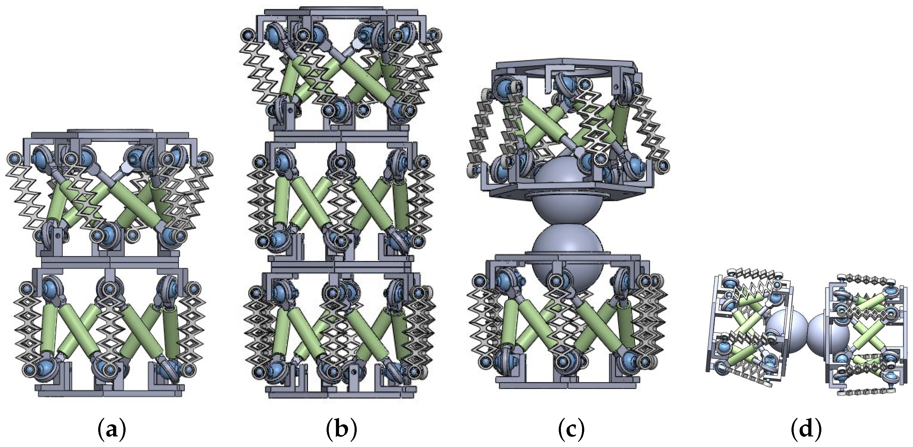
A structure having several Kresling layers (for example five) is able to generate a cylinder composed by the same number of sections. The versatility of this design allows each section to be compressed or extended independently, so the five-section cylinder can have a variety of possible lengths, where the maximum height is the extended height of all sections. This cylinder model meets the scalability parameter by its bending property and the number of sections mentioned above. Now, the challenge is to make the cylinder reconfigurable. To achieve this, a number of cylinders have been joined together. Each cylinder is renamed as link, regardless of its number of sections, and one layer will be renamed as single link. The link connection represents a greater challenge, because it requires a mechanism at each end of the link, as shown in Figure 3a, where the input IN and output OUT unions of the link are shown in blue and orange, respectively. This allows the link to know which end has been placed in the next link.
The joint between links is very wide, and ideally should rotate along the three axes X Y Z and allow mobility in the angles yaw ψ , pitch ρ and roll ϕ (Figure 3b). The ideal joints will enable as many links to be joined as required. The links should always be joined in an orderly sequence, so that there is an IN joint at the beginning of the chain and an OUT joint at the end. Using this pattern, each link has corresponding position within the chain, with the first link acting as the main or master link.
The ideal case with three rotation axes allows the kinematic chain to move either in a plane or in the three dimensional space. If the yaw angle ψ is rotated in a plane, a snake-like movement will be obtained, while the rotation of roll angle ϕ through space can be assimilated to the behavior of a finger or an arm, according to the number and length of the connected links, as shown in Figure 3c.

Link Prototype

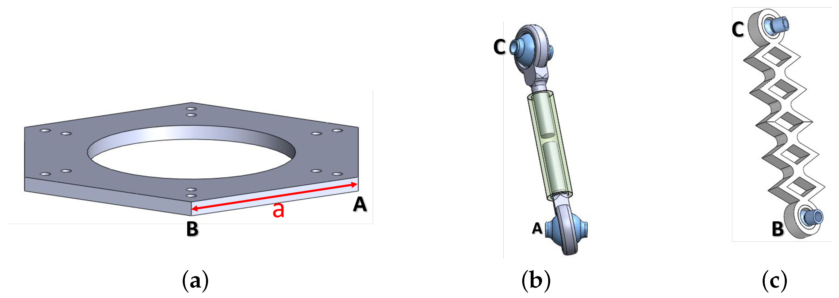
Our aim was to build a prototype to validate the idea of modular and scalable links, designing a paperless origami model. With this purpose, all the parts were modeled using CAD design applications and made using 3D printing technologies. Figure 4 illustrates the basic parts to generate the triangular polyhedron for a cylinder with six faces ( n = 6 ) . The base with constant length a is shown in Figure 4a. The l A C (Figure 4b) was designed as a variable length piston with spherical bearings at its ends for mobility. Finally, the length l B C is a soft material spring that can be warped with spherical bearings as well (Figure 4c). Values l B C and a have been deemed constant, following Jianguo et al.’s suggestion [33], and l A C is the only variable. In this case l B C = L B C . This design allows for operation while keeping constant values, but at the same time, its flexibility enables the free movement of the link. Design dimensions are a = 35 mm, α = 38 , β = 30 , r = 30 and planar state lengths L A C = 64.90 mm, L B C = 43.09 mm. The piston length l A C decreases when the structure deploys and its size increases during the collapse.
Figure 5 illustrates the single link prototype, which represents an assembly of the components shown in Figure 4. In addition, connecting couplings and pins were required to keep the link assembled but still able to move. The triangles were assembled according to the design in Figure 1, where l A C is folded inside the link, and l B C is outside. Therefore, the bistable movement from the deployed to the collapsed state generates a clockwise rotation of the angle θ .
Several single links can be nested between them to obtain a cylinder with multiple sections. The union of two ( h 2 ) is shown in Figure 6a, whereas a cylinder with three sections ( h 3 ) is shown in Figure 6b. Each of these groupings constitutes an independent link, which is capable of modifying its length by varying the h value in each section, in an adjustable way. As discussed before, another option providing a relative 3 D o F link movement is the two-part ball socket. This configuration features two ball joints connected through a fixed union, attached to both links. The spherical bearing allows free rotation between the axes. However, for the construction and operation of this coupling, a more complex design is required.
Figure 6c illustrates the union of two links through the spherical joint, where both bodies are aligned with each other in a starting position, with each body consisting of a single link and fully deployed. On the other hand, in Figure 6d the chain of cylinders is horizontal and shows a slight rotation in the roll angle. The double spherical bearing represents the IN joint and OUT joint, respectively, as described in Figure 3b.
Finally, the prototype components were built in a 3D printer and assembled. The hexagonal bases (length a), the couplings, and the pistons ( l A C ) were made of Polylactic Acid (PLA) plastic material. The bar l B C was manufactured with a flexible material (NinjaFlex) from the manufacturer NinjaTek, to allow short displacements and keep the structure stable. Metric (M2) screws and 2 mm nuts were used for the final assemble of the prototype.
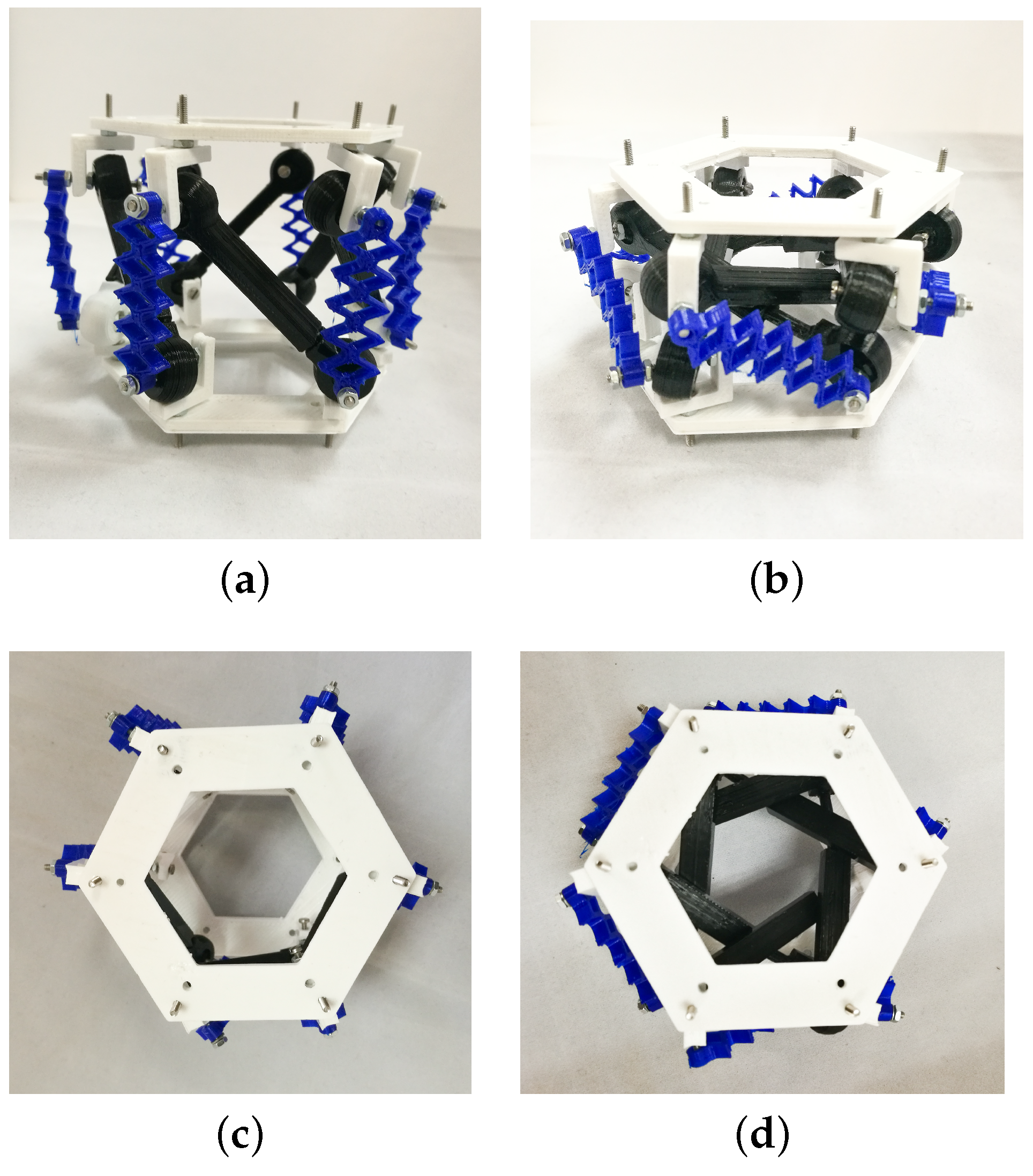
Figure 7 shows the bistate of the single link prototype assembly. The completely unfolded polyhedron is shown in Figure 7a. In this state the l A C pistons are compressed and the l B C soft links are extended. The final position of the deployment depends on l A C , as mentioned before, and l B C is adapted to that length.
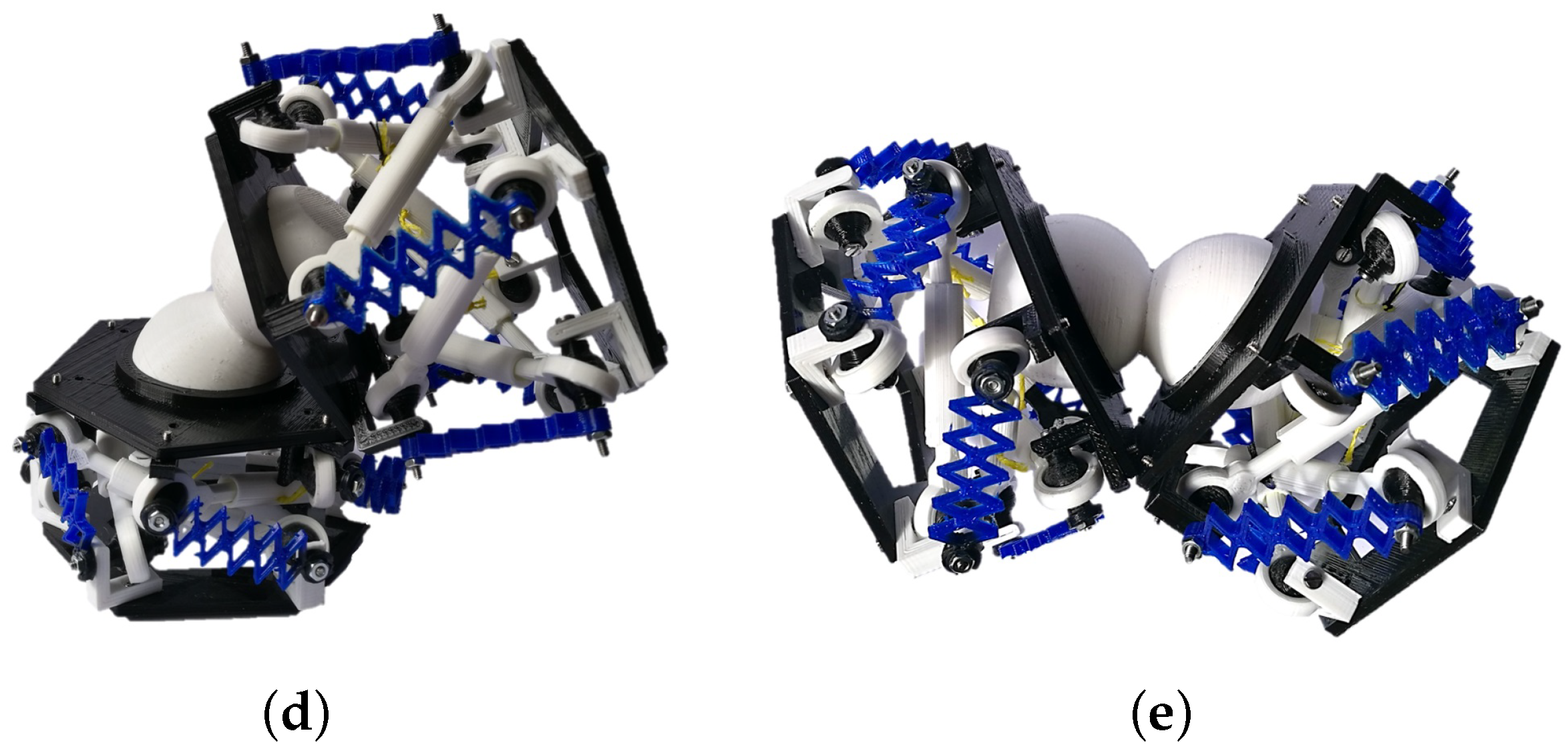
In addition, the nested links were assembled to validate the design, as shown in Figure 8. The changing link size feature has been checked; each single link is able to fold and deploy in a two-sections link according to Figure 8a,b. The spherical joint shown in Figure 8c allows the union and the rotation of two single links while keeping the bistable operation.

3. Cable-Driven Prototype

The prototypes presented in the last section validate the design of this proposal; however, the bistable behavior is binary. The link has two possible positions, completely collapsed and completely deployed. Therefore, the change of size does not have intermediate steps. Our proposal aims to obtain a self-scaling simple link with a continuous change of the size. For this purpose, a spring and a cable-driven mechanism have been included in the link. The final movement of each cylinder is composed by 2 D o F : displacement in z ( h ) and rotation in θ . Using three tendons and only one motor provides both movements if attached correctly. The internal spring is needed because of the structure of the link, that is not capable of maintaining an intermediate position and will fold without an external agent providing an extension force. Figure 9 illustrates the simple link prototype with an internal spring and a cable-drive with three tendons. Between the top of the single link and the top of spring, a bearing has been installed, which allows a free spring rotation movement when θ changes during collapse and deployment.
The cable-drive is actuated by a DC motor with a 210:1 gear and no load speed of 75 ( R P M ) . It also features an encoder composed by two hall effect sensors displaced 90 between each other and a wheel with seven switching magnets. Therefore, one motor rotation corresponds to 28 quadrature pulses. As the gear ratio is 210:1, a 360 turn in the gear part corresponds to 5880 counts of the encoder. That makes the resolution of the encoder on the outside part 0 . 06 .
The spring elastic constant has been obtained experimentally. Masses between 0 ( g r ) and 400 ( g r ) have been placed in the upper base of the spring and the deformation lengths corresponding to the compression have been registered in Table 1, from which the elastic constant has been approximated to a straight line F = K · x .
A simple linear regression has been applied to the collected data shown in Figure 10, from which the polynomial in Equation (5) is obtained, where the slope corresponds to the value of the constant K.
F ( x ) = 70.9522 x + 9.5803
K = 70.9522 [ N / m ]
The prototype is expected to validate self-scaling in an autonomous and controlled manner. Given that the considered prototype physical definition is complex and consists of several subsystems, starting from the actuator used for the robot positioning and followed by the complete link, a system identification was performed in order to obtain the plant model.
The origami link is divided into two physical systems, the link itself, and the DC motor driving the mechanism. Given the link geometry described in the previous sections, we can neglect its effects in the final behavior and model the plant based on the DC motor only. Due to the lack of information from the motor provider, the DC motor model was obtained using recursive least squares (RLS) identification to the input-output captured data.

3.1. Motor System Identification

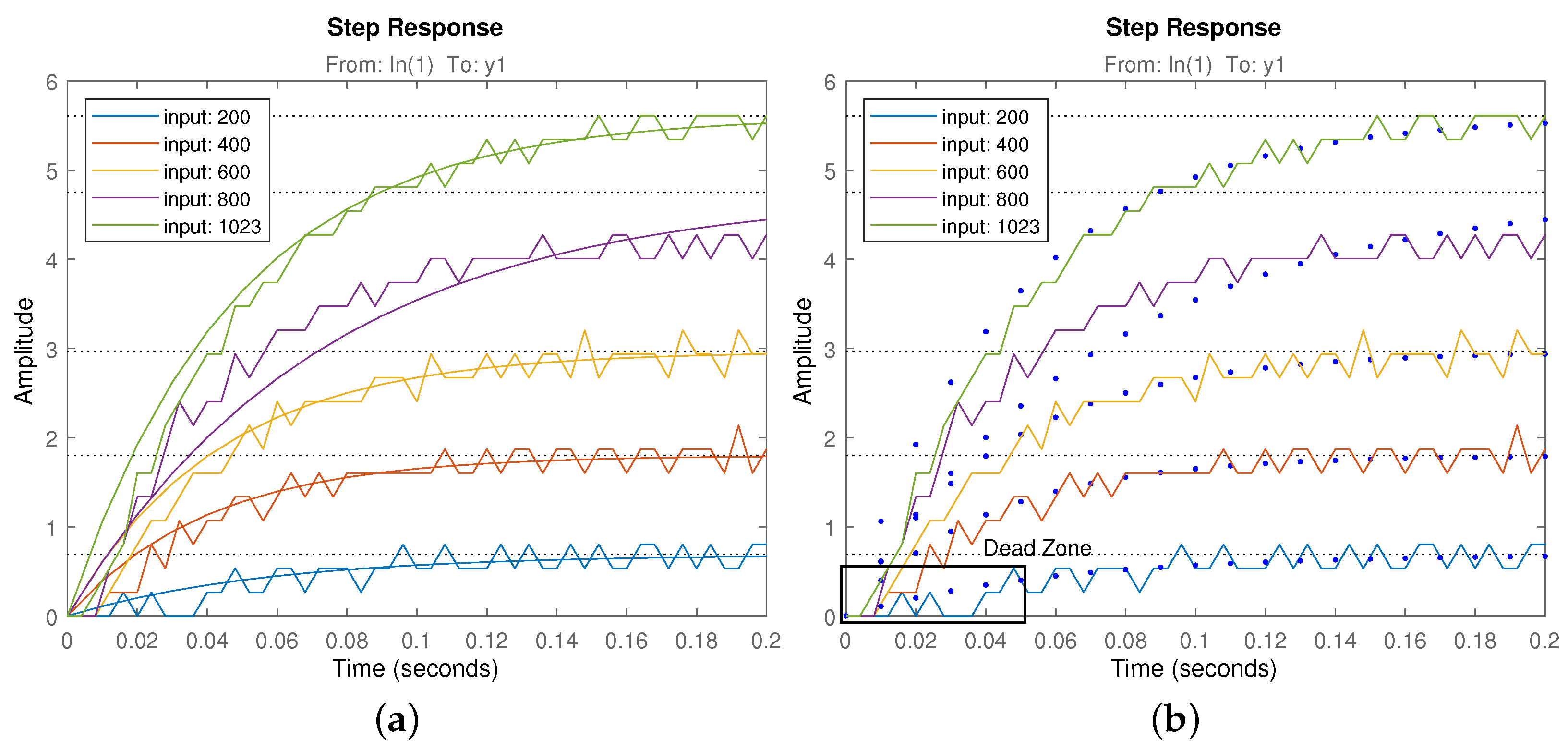
The model considered for identification is the DC motor (and gear) used in the pull mechanism of the robot. Identification data was captured using different input steps of [ 1 , 2 , 3 , 4 , 5 ] Volts corresponding to throttle input values of [ 200 , 400 , 600 , 800 , 1023 ] . A small gain variation was observed for the different input values, resulting in several transfer functions. In order to use a single model, the average will be considered. The time responses of the identification results and the average transfer function considered are shown in Figure 11 including the identification captured data.
Observe how the maximum possible velocity is close to 6 rad/s, meaning a saturation of the system velocity for inputs of this value and higher. In addition, given the low cost approach of the design, the motor open loop response is noisy and shows dead zones. Therefore, a velocity feedback is proposed to obtain a linear behavior in the motor side.

3.2. Controller Design

The average transfer function found through RLS identification is shown in Equation (7). This is the low level plant model used for the low level velocity control loop.
G v ( s ) m o t o r = 0.09991 s + 19.11
The proposed control scheme is shown in Figure 12. It consists of a feedback loop having a controller with reference in Velocity (rad/s) and output in the same units. As the motor model considered is the one discussed above, the control signal is the motor throttle (0–1023), with a saturation in 1023.
Given the plant gain variability detected, a robust control is proposed to cope with that plant parameter uncertainty. The controller tuning method proposed is the iso-m described in [35], which includes the robustness conditions in the tuning algorithm. Similar to many fractional order controller tuning methods, the desired performance specifications are based on the phase margin and crossover frequency features of the open loop frequency response. These are related to closed loop features such as bandwidth frequency and resonant peak height, which in turn are related to transient time response properties such as overshoot and peak time. Table 2 shows a summary of the most common constraints used in the frequency domain and time domain to define performance specification.
It is a common practice to define the system performance by means of the open loop frequency variables (see [36]). In similar works like [37,38], the usual control specifications are crossover frequency ( ω g c ) and phase margin ( ϕ m ). As stated, the first is related to the system responsiveness (peak time) and the second to stability (overshoot). Equations (8) and (9) formulate these specifications, respectively:
| C ( j ω g c ) G ( j ω g c ) | d B = 0 dB ,
arg ( C ( j ω g c ) G ( j ω g c ) ) = π + ϕ m ,
where C ( j ω g c ) is the controller frequency response at ω g c , G ( j ω g c ) is the plant frequency response at ω g c , and ϕ m is the desired open loop phase margin for the controlled system.
Once the gain crossover frequency ω g c and the phase margin ϕ m are set, following the steps described in [35] will provide a solution for the controller parameters using the iso-m method.
Given the method’s flexibility, both fractional and integer order controllers can be used, allowing a comparison between their results.
The integer order controller is defined by
I O P I ( s ) = k p + k i / s ,
kp and ki being the proportional and integral controller gains, while the fractional order controller is defined by
F O P I ( s ) = k p + k a / s α ,
where kp and ka are the proportional and integral controller gains and α the fractional order of the integral operator.
Note that the number of parameters available for tuning while using the IOPI integer controller Equation (10) is not enough to fulfill the three specifications. This restricts the possible tuning inputs in that case, requiring a decision between overshoot ( ϕ m ) or responsiveness ( ω g c ). Then, the remaining specification will be given by the system characteristics and the chosen specification. A controlled overshoot is important to assure a good upper level control loop behavior; therefore, it will be defined using a phase margin of ϕ m = 80 deg for the tuning of both controllers.
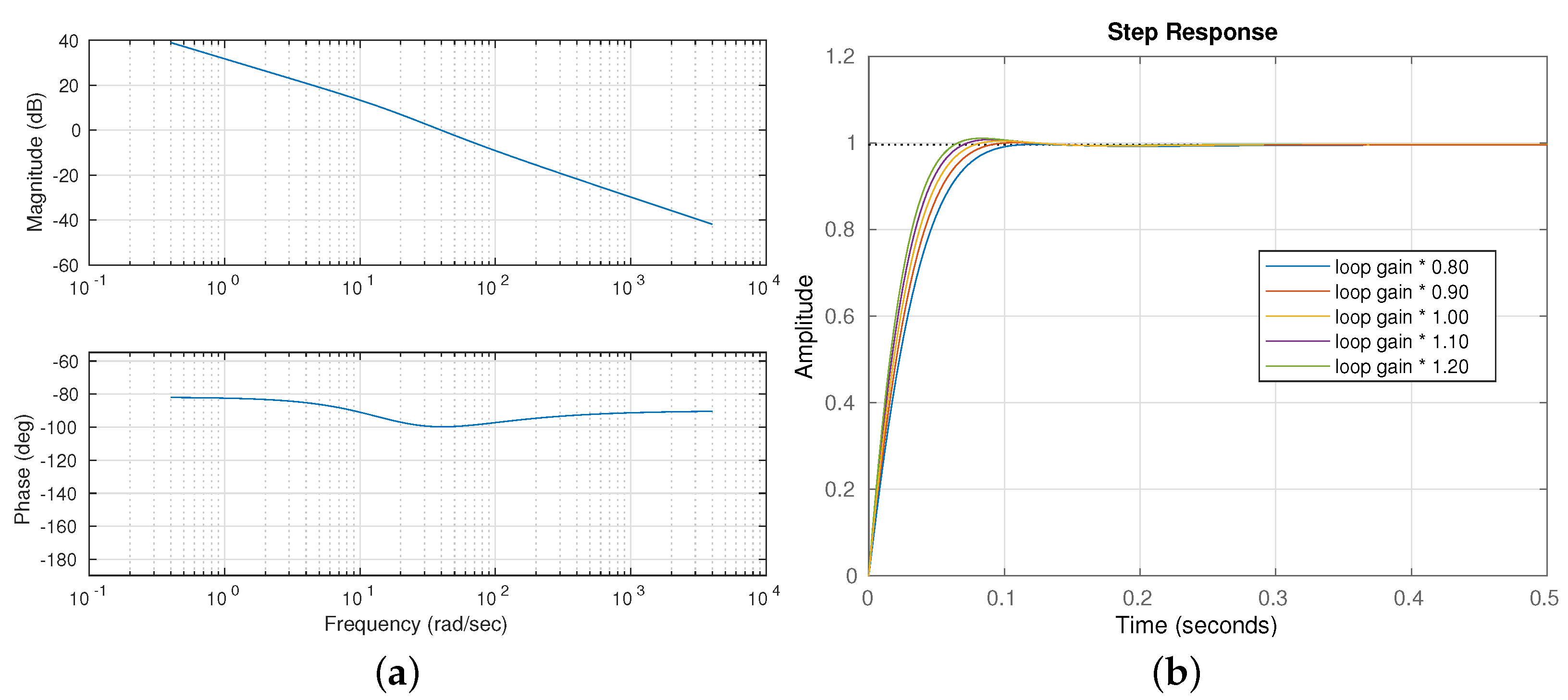
In the IOPI case, this fully defines the controller using the iso-m method. Using the algorithm described in [35], the tuning parameters obtained were k p = 163.9 and k i = 4462.3 . The responsiveness depends on the other values, resulting ω g c = 20 rad/s in this case. Figure 13 shows the frequency open loop response and the expected closed loop time response for different plant gains using the integer order controller.
In the case of the FOPI controller, the two specifications described above can be used for controller tuning. The fractional order operator improved flexibility allows us to double the responsiveness while keeping the same robustness compared to the previous results. Therefore, ϕ m = 80 and ω g c = 40 rad/s can be used to specify the closed loop behavior. Using the algorithm described in [35], the tuning parameters obtained were α = 0.9100 , K p = 323.9 , K a = 7388.5 . Figure 14 shows the frequency open loop response and the expected closed loop time response for different plant gains.
The resulting plant in closed loop is a velocity reference input, real plant velocity output system described by Equation (12). Both measured and reference value units are rad/s. Therefore, the output obtained from the actuator is also expressed in rad/s with a maximum possible value of 5.5 rad/s.
F v ( s ) m o t o r = 16.38 s + 445.8 s 2 + 35.49 s + 445.8
Using an integrator on F v ( s ) , the resulting plant G p ( s ) = F v ( s ) / s is the velocity input, position output system with 1 rad/s crossover frequency.
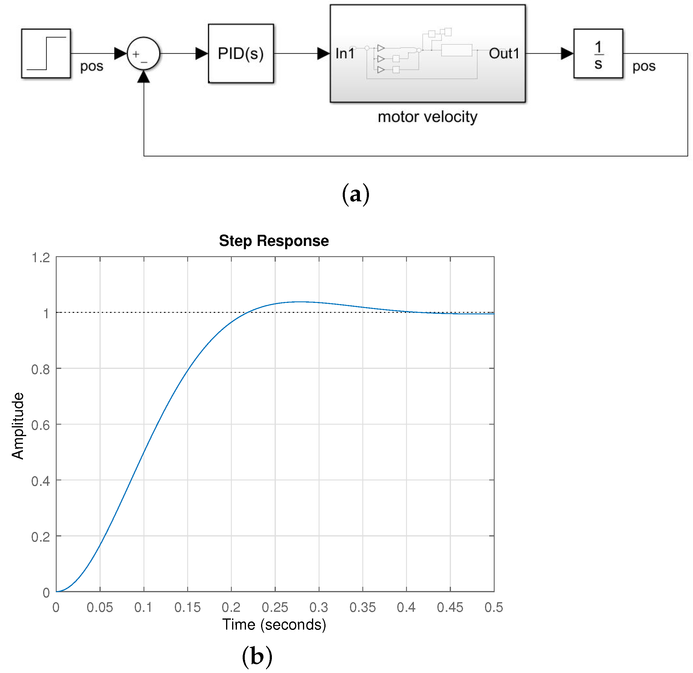
Using this plant model, a high level position loop was designed. Given the convenient low level system response, we can design our servo-system using a feedback loop with a simple proportional controller. The designed position closed loop is shown in Figure 15.
The expected time response of a controller with a gain of 10 (Kp = 10) is also shown in Figure 15. This control scheme defines the position output of the motor shaft from an input reference (in (rad) units).

3.3. Whole System Behavior

Using the actuator described, an input step was performed in the robot. Given the results of the model simulation compared to the real response obtained, we can say that both systems are similar, concluding that the spring and the origami shape are not changing the behavior of the actuator plant. Therefore, we can find a model based on the feedback loop proposed resulting in a transfer function as follows:
G p ( s ) o r i g a m i = 163.8 s + 4458 s 3 + 35.49 s 2 + 609.6 s + 4458
In order to validate the model, a step input of 0.5 rad (saturation will happen in the motor for higher targets) was fed into the system, resulting in the time response shown in Figure 16. The open loop frequency response of the whole system model is also shown in the figure, with a phase margin of P m = 65.4 deg at a gain crossover frequency ω c = 9.62 rad/s.

4. Results

A Matlab simulation scheme has been created to validate the kinematics for both simple and nested links with two and three sections. The main parameters a, α and β were used to compute the origami behavior while the height h was the input data to fold or deploy the origami. Taking Equation (4) into account, the maximum height is when δ = 90 and the structure is completely deployed. This position is not achieved in the prototype because the spring force does not generate enough rotation for the links to change position at a positive θ angle and reach δ = 90 .
Figure 17 shows the kinematics simulation for a single link with different heights. The change of the rotation angle θ can be seen while the origami is deploying. The simulation results are shown in Table 3.
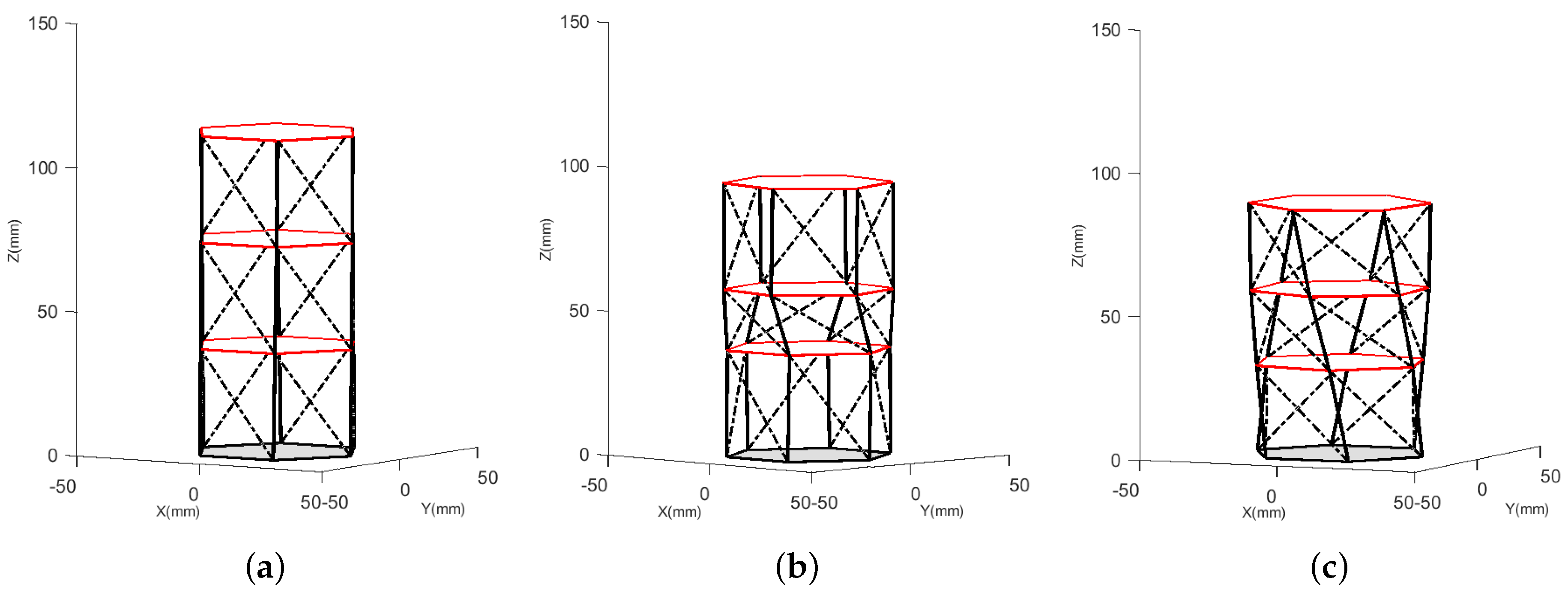
The nested link has been simulated, too. In this case the total link height is the sum of each single link. To achieve a certain height position, we can actuate each individual link or all at once. Figure 18 shows three different configurations: completely deployed link, only one section folding, and three sections folding. The data results from this simulation are shown in Table 4.

Single Link Cable-Driven Prototype Experimental Results

Position control tests have been carried out with both the integer and the fractional controllers adjusted. The tests were made according to encoder data in r a d ; however, the origami linear displacement is easy to obtain knowing that the motor coupling radius is 7.5 (mm) and the encoder resolution is 5580 counts per turn. The linear displacement corresponds to the origami folding, and height h and rotation angle θ can be indirectly calculated.
Two tests have been designed. The first consists of giving the system individual targets in position: 0.5, 1.0, 1.5, 2.0 and 2.2 ( r a d ) . The physical behavior of the system can be seen in Figure 19, where the initial reference of the upper part of the origami and the union of the three tendons to visualize the displacement has been marked with a red dashed line.
The data results obtained are shown in Figure 20. The saturation of the system is evident in the higher set points, showing an overshoot in the response of the system. The control signals of the internal loop in speed and the external loop in position are shown in Figure 21.
Table 5 shows the experimental kinematic data, which have been calculated indirectly according to the experimental position changes in the first test. For this purpose, the initial position of the prototype with angle θ = 0.0514 (rad) and initial height h = 39.44 (mm) has been considered, resulting in a maximum δ = 85.64 (deg). The position data were measured for all targets once the system reached its permanent state, at time t = 4 s.
A simulation was performed with the obtained δ data in order to make a comparison between experimental and simulation data in terms of height h and angle θ . The resulting errors are shown in Table 5. The difference between the real measured and simulated values is clearly the value of l B C , since in the measured value l B C r e a l = 39.56 (mm) and in the simulated value l B C s i m = 43.09 (mm). This difference is due to the fact that in the assembled prototype the link representing l B C is slightly compressed to maintain the desired position of the structure.
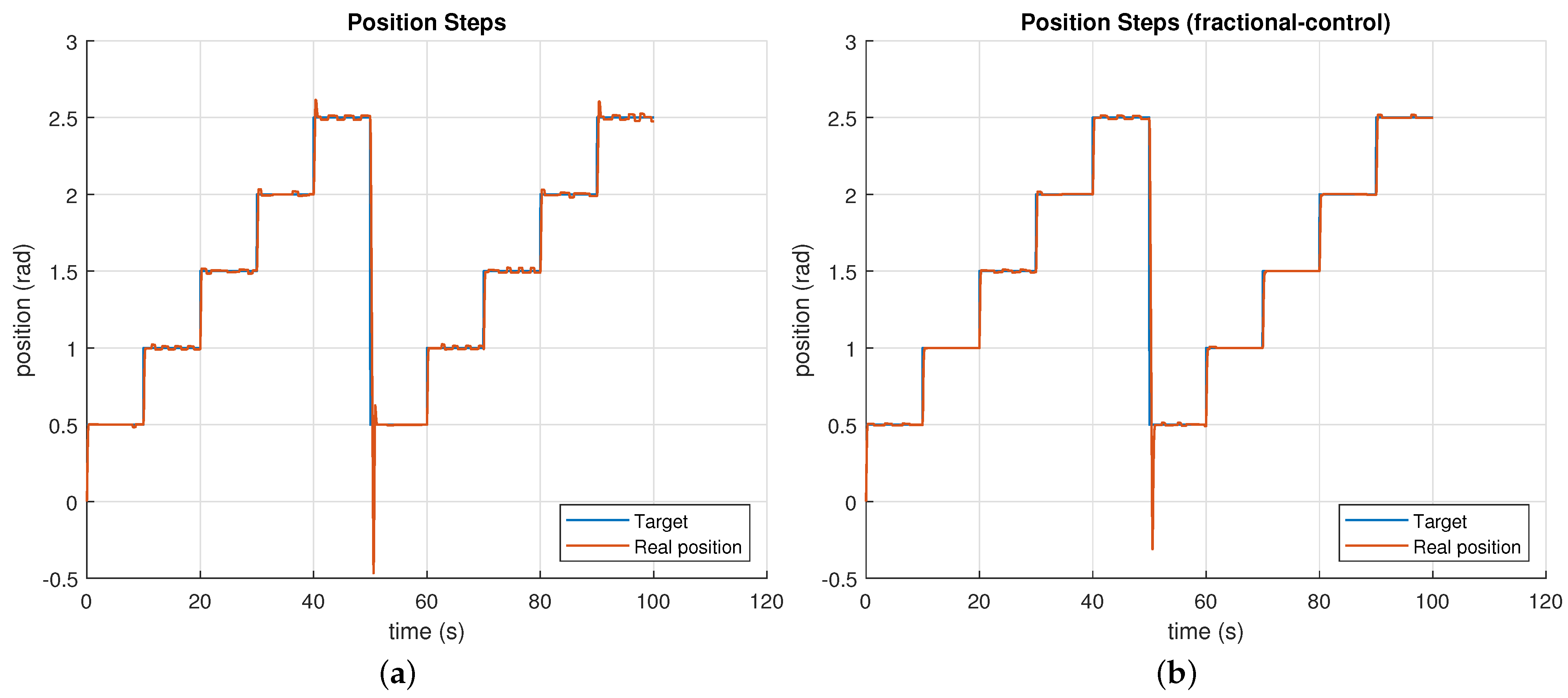
The second test consists in giving the system sequential targets between 0.5 and 2.5 rad with steps of 0.5 rad. The results are shown in Figure 22, where the real position data is in red. Here we can see an expected behavior for the designed controllers. The overshoot in each step is lower than in the first test because the sequential targets are lower than the individual ones.
On the other hand, when the loop is restarted and the position must change from 2.5 to 0.5 rad, the system behavior is the opposite, that is, it must change from folding to deploying. In that case, the position reaches the target with an initial overshoot but quickly stabilizes. In this way, the efficiency and robustness of the control system have been validated.
The video of the performance of this test can be visualized in the following link: https://cutt.ly/rjW0Obi, available since 14 January 2021.
To verify the robustness of both the control and the structure, the steps were tested with different payloads between 100 and 400 g, as shown in Figure 23.
The results obtained allow for the determination of the behavior of the integer and fractional controllers (Figure 24), where the most relevant behavior is shown in the return zone from 2.5 (rad) to 0.5 (rad).
In the case of the integer controller (Figure 24a), the lower peak position reaches 0.54 (rad) with a stabilization time of 0.63 (s) and a maximum overshoot of 16 % , while in the case of the fractional controller (Figure 24b), the minimum position is 0.44 (rad); it has no overshoot and the stabilization time is 0.43 (s). Therefore, it can be concluded that the fractional controller is not only robust but also faster than the integer controller.
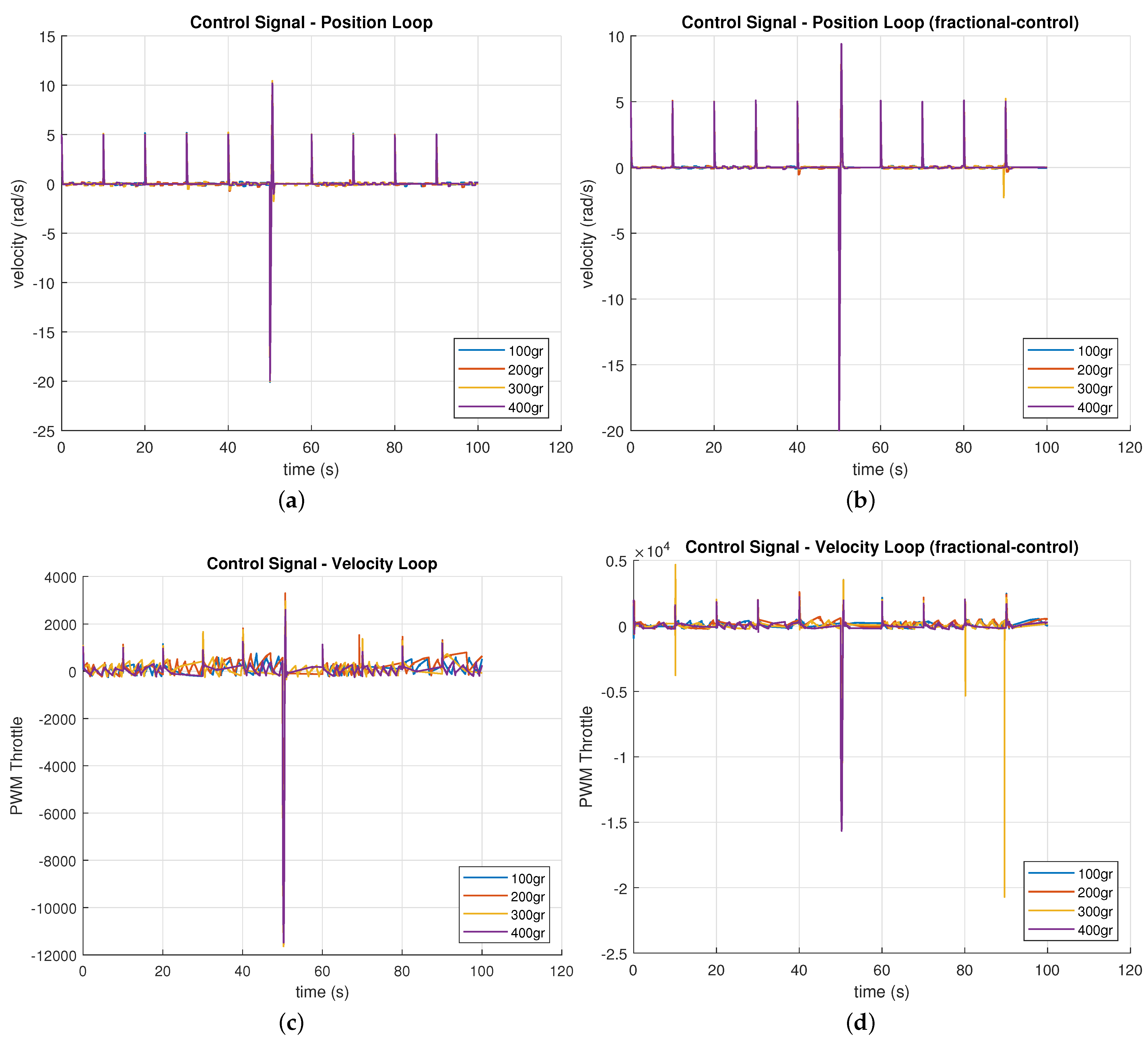
The control signals for both controllers are shown in Figure 25.
It is interesting to mention that in this last test the loads were placed in a distributed way so that the center of mass does not change. In case the loads were placed off-center or unbalanced, the dynamics of the system would change because an additional DoF would be generated, allowing the upper base of the platform to tilt in the direction of the weight. For these scenarios more than one actuator would be required in order to compensate this tilt movement (and other actuators could be included to generate other different DoF). This is an interesting topic to be developed in future works.

5. Conclusions

A design proposal has been presented for a scalable and modular link, inspired by origami structures. The validation of the kinematics for both single and nested links has been successfully carried out. In the case of the nested link, the change in length of the link can be done by completely folding one of the single links or by doing a proportional folding on each single link.
A simple link prototype has been built and experimentally tested to validate its scalability and shape change. The model with three tendons actuated by a motor allows the folding of the origami structure while an internal spring generates the unfolding.
Compared to other platforms such as [21], which are manually controlled, in our study we included system modeling and controller tuning for automatic operation in position control of the prototype.
The single link prototype has been successfully controlled in position mode. The position control has been done with two control loops for the correct operation of the motor. The internal loop allows for the elimination of the dead zones of the motor with a velocity control and with the external loop the origami position is controlled. The internal loop has been designed and tested with two controllers, integer and fractional, where the single link has been tested for correct operation with and without payload.
The identification of the whole system was carried out considering these two control loops; otherwise, the direct identification of the system would have resulted in a nonlinear system, due to the saturation and the dead zone of the motor.
It is also important to remark that the rotational movement of the Kresling pattern can be seen as an advantage that allows the orientation of the platform. However, the rotation can be canceled by coupling two simple links with opposite rotation, if only a prismatic displacement is required.
Some of the main limitations of the system are due to the fact that it is a very low cost 3D printed prototype that needs the adjustment of the mechanical parts and the use of a better motor. However, despite these limitations, the prototype works properly and the design has been validated.
Future works include the improvement of the mechanical and actuation parts of the link and the introduction of distance and rotation sensors to enhance the position accuracy h and rotation angle θ , which are now obtained indirectly. Besides, the development of the three-dimensional joint to interconnect several links is one of our major objectives, which will allow us to implement and test modularity.

Author Contributions

Conceptualization, L.M.; methodology, L.M.; software, L.M. and J.M.; validation, L.M. and J.M.; investigation, L.M., C.A.M., and J.M.; resources, C.A.M. and C.B.; data curation, L.M. and J.M.; writing—original draft preparation, L.M. and J.M.; writing—review and editing, C.A.M.; supervision, C.A.M. and C.B.; project administration, C.A.M. All authors have read and agreed to the published version of the manuscript.

Funding

The research leading to these results has received funding from the project Desarrollo de articulaciones blandas para aplicaciones robóticas, with reference IND2020/IND-1739, funded by the Comunidad Autónoma de Madrid (CAM) (Department of Education and Research), and from RoboCity2030-DIH-CM, Madrid Robotics Digital Innovation Hub (Robótica aplicada a la mejora de la calidad de vida de los ciudadanos, FaseIV; S2018/NMT-4331), funded by “Programas de Actividades I+D en la Comunidad de Madrid” and cofunded by Structural Funds of the EU.

Institutional Review Board Statement

Not applicable.

Informed Consent Statement

Not applicable.

Data Availability Statement

The data presented are available on request from the corresponding author.

Conflicts of Interest

There are no conflict of interest to declare.

Abbreviations

The following abbreviations are used in this manuscript:
MRSModular robotic system
MITEModule, information, task, and environment
DoFDegrees of freedom

References

  1. Fukuda, T.; Nakagawa, S. Approach to the dynamically reconfigurable robotic system. J. Intell. Robot. Syst. 1988, 1, 55–72. [Google Scholar] [CrossRef]
  2. Schmitz, D. The CMU Reconfigurable Modular Manipulator System; Technical Report; The Robotics Institute, Carnegie Mellon University: Pittsburgh, PA, USA, 1988. [Google Scholar]
  3. Ahmadzadeh, H.; Masehian, E.; Asadpour, M. Modular robotic systems: Characteristics and applications. J. Intell. Robot. Syst. 2016, 81, 317–357. [Google Scholar] [CrossRef]
  4. Yim, M. A reconfigurable modular robot with multiple modes of locomotion. In Proceedings of the 1993 JSME Conference on Advanced Mechatronics, Tokyo, Japan, August 1993. [Google Scholar]
  5. Qiao, G.; Song, G.; Wang, W.; Zhang, Y.; Wang, Y. Design and implementation of a modular self-reconfigurable robot. Int. J. Adv. Robot. Syst. 2014, 11, 47. [Google Scholar] [CrossRef] [Green Version]
  6. Murata, S.; Kurokawa, H.; Kokaji, S. Self-assembling machine. In Proceedings of the 1994 IEEE International Conference on Robotics and Automation, San Diego, CA, USA, 8–13 May 1994; IEEE: New York, NY, USA, 1994; pp. 441–448. [Google Scholar]
  7. Murata, S.; Kurokawa, H. Prototypes of self-organizing robots. In Self-Organizing Robots; Springer: Tokyo, Japan, 2012; pp. 105–130. [Google Scholar]
  8. Inou, N.; Kobayashi, H.; Koseki, M. Development of pneumatic cellular robots forming a mechanical structure. In Proceedings of the 7th International Conference on Control, Automation, Robotics and Vision, 2002, ICARCV 2002, Singapore, 2–5 December 2002; IEEE: New York, NY, USA, 2002; Volume 1, pp. 63–68. [Google Scholar]
  9. Romanishin, J.W.; Gilpin, K.; Rus, D. M-blocks: Momentum-driven, magnetic modular robots. In Proceedings of the 2013 IEEE/RSJ International Conference on Intelligent Robots and Systems, Tokyo, Japan, 3–8 November 2013; IEEE: New York, NY, USA, 2013; pp. 4288–4295. [Google Scholar]
  10. Wolfe, K.C.; Moses, M.S.; Kutzer, M.D.; Chirikjian, G.S. M 3 Express: A low-cost independently-mobile reconfigurable modular robot. In Proceedings of the 2012 IEEE International Conference on Robotics and Automation, St. Paul, MN, USA, 14–18 May 2012; IEEE: New York, NY, USA, 2012; pp. 2704–2710. [Google Scholar]
  11. Hong, W.; Wang, S.; Shui, D. Reconfigurable robot system based on electromagnetic design. In Proceedings of the 2011 International Conference on Fluid Power and Mechatronics, Beijing, China, 17–20 August 2011; IEEE: New York, NY, USA, 2011; pp. 570–575. [Google Scholar]
  12. Sadjadi, H.; Mohareri, O.; Al-Jarrah, M.A.; Assaleh, K. Design and implementation of HexBot: A modular self-reconfigurable robotic system. J. Frankl. Inst. 2012, 349, 2281–2293. [Google Scholar] [CrossRef]
  13. Davey, J.; Kwok, N.; Yim, M. Emulating self-reconfigurable robots-design of the SMORES system. In Proceedings of the 2012 IEEE/RSJ International Conference on Intelligent Robots and Systems, Vilamoura, Algarve, Portugal, 7–12 October 2012; IEEE: New York, NY, USA, 2012; pp. 4464–4469. [Google Scholar]
  14. Lyder, A.; Garcia, R.F.M.; Stoy, K. Genderless connection mechanism for modular robots introducing torque transmission between modules. In Proceedings of the ICRA Workshop on Modular Robots, State of the Art, Anchorage, Alaska, 3 May 2010; pp. 77–81. [Google Scholar]
  15. Yu, C.H.; Haller, K.; Ingber, D.; Nagpal, R. Morpho: A self-deformable modular robot inspired by cellular structure. In Proceedings of the 2008 IEEE/RSJ International Conference on Intelligent Robots and Systems, Nice, France, 22–26 September 2008; IEEE: New York, NY, USA, 2008; pp. 3571–3578. [Google Scholar]
  16. Galloway, K.C.; Jois, R.; Yim, M. Factory floor: A robotically reconfigurable construction platform. In Proceedings of the 2010 IEEE International Conference on Robotics and Automation, Anchorage, AK, USA, 3–7 May 2010; IEEE: New York, NY, USA, 2010; pp. 2467–2472. [Google Scholar]
  17. Lyder, A.; Garcia, R.F.M.; Stoy, K. Mechanical design of odin, an extendable heterogeneous deformable modular robot. In Proceedings of the 2008 IEEE/RSJ International Conference on Intelligent Robots and Systems, Nice, France, 22–26 September 2008; IEEE: New York, NY, USA, 2008; pp. 883–888. [Google Scholar]
  18. Shimizu, M.; Ishiguro, A.; Kawakatsu, T. A modular robot that exploits a spontaneous connectivity control mechanism. In Proceedings of the 2005 IEEE/RSJ International Conference on Intelligent Robots and Systems, Edmonton, AB, Canada, 2–6 August 2005; IEEE: New York, NY, USA, 2005; pp. 1899–1904. [Google Scholar]
  19. Donald, B.R.; Levey, C.G.; McGray, C.D.; Paprotny, I.; Rus, D. An untethered, electrostatic, globally controllable MEMS micro-robot. J. Microelectromechan. Syst. 2006, 15, 1–15. [Google Scholar] [CrossRef]
  20. Suzuki, R.; Zheng, C.; Kakehi, Y.; Yeh, T.; Do, E.Y.L.; Gross, M.D.; Leithinger, D. ShapeBots: Shape-changing Swarm Robots. In Proceedings of the 32nd Annual ACM Symposium on User Interface Software and Technology, New Orleans, LA, USA, 20–23 October 2019; pp. 493–505. [Google Scholar]
  21. Matsuo, H.; Asada, H.H.; Takeda, Y. Design of a Novel Mutliple-DOF Extendable Arm With Rigid Components Inspired by a Deployable Origami Structure. IEEE Robot. Autom. Lett. 2020, 5, 2730–2737. [Google Scholar] [CrossRef]
  22. Hatori, K. History of Origami in the East and the West before Interfusion. In Origami 5: Fifth International Meeting of Origami Science, Mathematics and Education; Singapore Management University: Singapore, 2010; pp. 1–13. [Google Scholar]
  23. Miura, K. Method of packaging and deployment of large membranes in space. Title Inst. Space Astronaut. Sci. Rep. 1985, 618, 1. [Google Scholar]
  24. Santoso, J.; Skorina, E.H.; Luo, M.; Yan, R.; Onal, C.D. Design and analysis of an origami continuum manipulation module with torsional strength. In Proceedings of the 2017 IEEE/RSJ International Conference on Intelligent Robots and Systems (IROS), Vancouver, BC, Canada, 24–28 September 2017; IEEE: New York, NY, USA, 2017; pp. 2098–2104. [Google Scholar]
  25. Firouzeh, A.; Paik, J. An under-actuated origami gripper with adjustable stiffness joints for multiple grasp modes. Smart Mater. Struct. 2017, 26, 055035. [Google Scholar] [CrossRef]
  26. Kuribayashi, K.; Tsuchiya, K.; You, Z.; Tomus, D.; Umemoto, M.; Ito, T.; Sasaki, M. Self-deployable origami stent grafts as a biomedical application of Ni-rich TiNi shape memory alloy foil. Mater. Sci. Eng. A 2006, 419, 131–137. [Google Scholar] [CrossRef]
  27. Zirbel, S.A.; Wilson, M.E.; Magleby, S.P.; Howell, L.L. An origami-inspired self-deployable array. In Proceedings of the ASME 2013 Conference on Smart Materials, Adaptive Structures and Intelligent Systems, Snowbird, UT, USA, 16–18 September 2013. [Google Scholar]
  28. Paez, L.; Agarwal, G.; Paik, J. Design and analysis of a soft pneumatic actuator with origami shell reinforcement. Soft Robot. 2016, 3, 109–119. [Google Scholar] [CrossRef]
  29. Kidambi, N.; Wang, K. Dynamics of Kresling origami deployment. Phys. Rev. E 2020, 101, 063003. [Google Scholar] [CrossRef] [PubMed]
  30. Kresling, B.; Abel, J.F. Natural twist buckling in shells: From the hawkmoth’s bellows to the deployable Kresling-pattern and cylindrical Miura-ori. In Proceedings of the 6th International Conference on Computation of Shell and Spatial Structures, Ithaca, NY, USA, 28–31 May 2008; Volume 11, pp. 12–32. [Google Scholar]
  31. Zhai, Z.; Wang, Y.; Jiang, H. Origami-inspired, on-demand deployable and collapsible mechanical metamaterials with tunable stiffness. Proc. Natl. Acad. Sci. USA 2018, 115, 2032–2037. [Google Scholar] [CrossRef] [PubMed] [Green Version]
  32. Hunt, G.W.; Ario, I. Twist buckling and the foldable cylinder: An exercise in origami. Int. J. Non-Linear Mech. 2005, 40, 833–843. [Google Scholar] [CrossRef]
  33. Jianguo, C.; Xiaowei, D.; Ya, Z.; Jian, F.; Yongming, T. Bistable behavior of the cylindrical origami structure with Kresling pattern. J. Mech. Des. 2015, 137. [Google Scholar] [CrossRef]
  34. Zhang, Q.; Cai, J.; Li, M.; Feng, J. Bistable behaviour of a deployable cylinder with Kresling pattern. In Proceedings of the 7th International Meeting on Origami in Science, Mathematics and Education (7OSME), Oxford, UK, 4–7 September 2018. [Google Scholar]
  35. Muñoz, J.; Monje, C.A.; Nagua, L.F.; Balaguer, C. A graphical tuning method for fractional order controllers based on iso-slope phase curves. ISA Trans. 2020. [Google Scholar] [CrossRef] [PubMed]
  36. Nise, N.S. Frequency response techniques. In Control Systems Engineering; Wiley: Pomona, CA, USA, 2019; Chapter 10; pp. 525–612. [Google Scholar]
  37. Chen, Y.; Moore, K.L. Relay Feedback Tuning of Robust PID Controllers with Iso-damping Property. IEEE Trans. Syst. Man Cybern. Part B 2005, 35, 23–31. [Google Scholar] [CrossRef] [PubMed]
  38. Monje, C.A.; Vinagre, B.M.; Santamaría, G.E.; Tejado, I. Auto-tuning of fractional order PIλDμ controllers using a PLC. In Proceedings of the 2009 IEEE Conference on Emerging Technologies Factory Automation, Palma de Mallorca, Spain, 22–25 September 2009; IEEE: New York, NY, USA, 2009; pp. 1–7. [Google Scholar] [CrossRef]
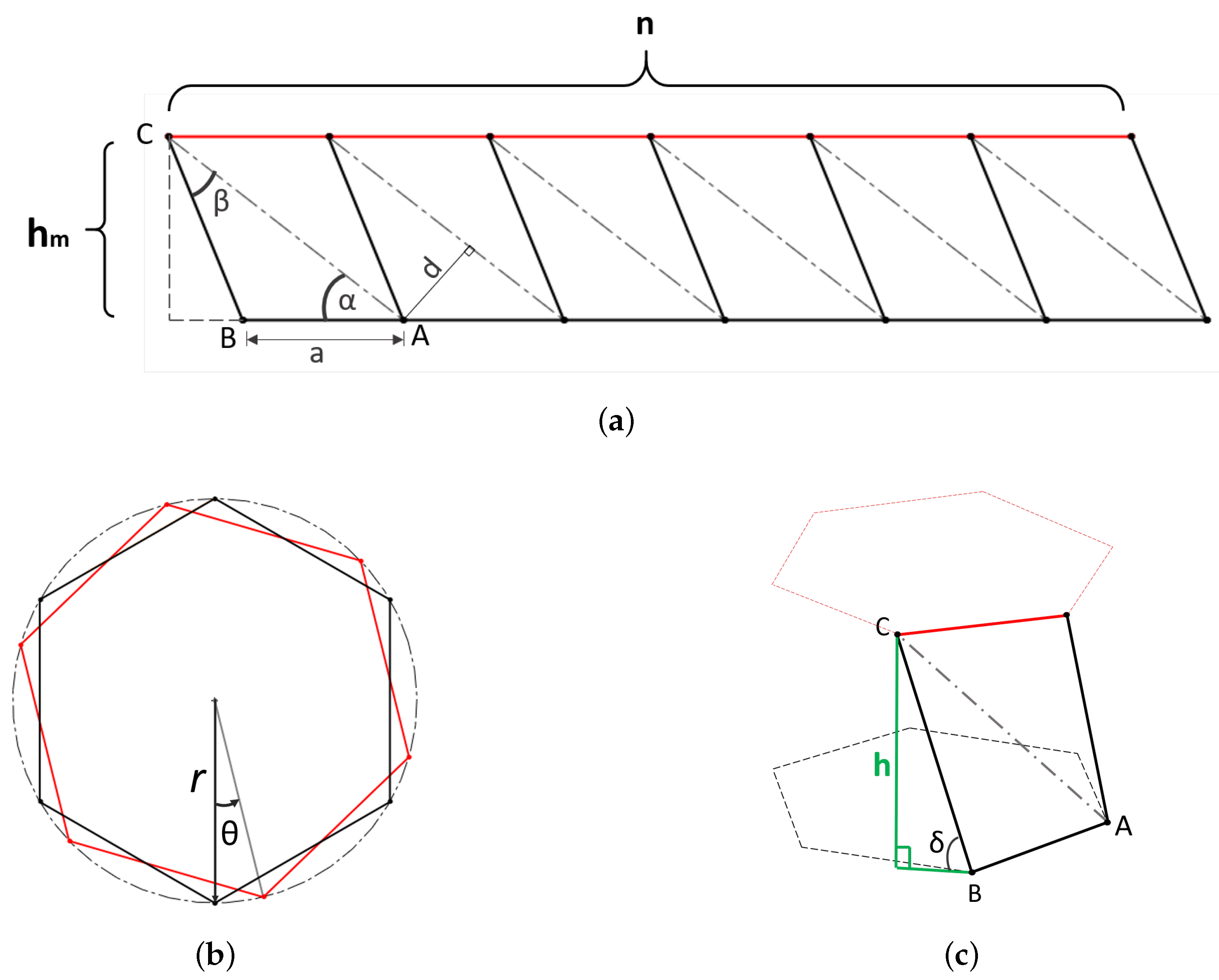
Figure 1. Origamipolyhedron Kresling pattern. (a) 2D Kresling pattern. (b) Folded cylinder link state. (c) Biestable behavior.
Mathematics 09 01324 g001
Figure 2. Cylinder polyhedron origami with one section ( h 1 ) and six faces ( n = 6 ). (a) Top view collapsed state. (bd) Folding state.
Mathematics 09 01324 g002
Figure 3. Connection of links. (a) Five-sections link with joints. (b) Joint between links. (c) Joined and reconfigurable links.
Mathematics 09 01324 g003
Figure 4. Components of the triangulated polyhedron prototype. (a) Constant base a. (b) Length l A C , greater displacement. (c) Length l B C , minor displacement.
Mathematics 09 01324 g004
Figure 5. Single link CAD prototype. (a) Collapsed state. (b) Folding state. (c) Deployed state.
Mathematics 09 01324 g005
Figure 6. Nested links CAD prototype. (a) two-sections link. (b) three-sections link. (c) Two single links with a joint. (d) Two single links with a joint rotated.
Mathematics 09 01324 g006
Figure 7. Single link first prototype. (a) Deployed single link prototype. (b) The single link is in collapsed state, and the height has changed. The l A C pistons are extended and l B C is slightly compressed. (c) Top view of the deployed prototype. (d) Top view of the collapsed prototype; the condition of the pistons and θ rotation are clearly shown.
Mathematics 09 01324 g007
Figure 8. Assembled nested links prototype. (a) Two-sections link collapsed. (b) Two-sections link deployed. (c) Two single links with a joint. (d) Two single links with a joint, vertically rotated and one of them extended. (e) Two single links with a joint, horizontally rotated and collapsed.
Mathematics 09 01324 g008aMathematics 09 01324 g008b
Figure 9. Cable-driven single link prototype.
Mathematics 09 01324 g009
Figure 10. Linear regression to obtain the spring elastic constant K from experimental data.
Mathematics 09 01324 g010
Figure 11. Motor system identification. Different systems identified depending on the inputs (a) and average system time response (b) compared to the captured data.
Mathematics 09 01324 g011
Figure 12. Motor velocity control system.
Mathematics 09 01324 g012
Figure 13. Open loop Bode diagram (a) and closed loop time response (b) for the integer order (IOPI) controller.
Mathematics 09 01324 g013
Figure 14. Open loop Bode diagram (a) and closed loop time response (b) for the fractional order (FOPI) controller.
Mathematics 09 01324 g014
Figure 15. Motor position control system. Motor position control system. (a) Control system diagram. (b) Step response.
Mathematics 09 01324 g015
Figure 16. Origami system identification. Step response in closed loop (a); Bode diagram in open loop (b).
Mathematics 09 01324 g016
Figure 17. Origami Kresling single link kinematics vadidation, with parameters α = 38 , β = 30 and a = 30 mm. (a) Collapsed state. (b) Deploying state. (c) Deployed state.
Mathematics 09 01324 g017
Figure 18. Three-sections link kinematics validation, with parameters α = 38 , β = 30 and a = 30 mm. (a) Completely deployed link. (b) Only one section folding. (c) Three sections folding.
Mathematics 09 01324 g018
Figure 19. Prototype test results with different target position.
Mathematics 09 01324 g019
Figure 20. Test results with different target positions. (a) Integer controller. (b) Fractional controller.
Mathematics 09 01324 g020
Figure 21. Control signals. (a) Position loop control signals with integer controller. (b) Position loop control signals with fractional controller. (c) Velocity loop control signals with Integer controller. (d) Velocity loop control signals with fractional controller.
Mathematics 09 01324 g021
Figure 22. Test results with sequential target positions. (a) Integer controller. (b) Fractional controller.
Mathematics 09 01324 g022
Figure 23. Prototype test results with different payloads in 2.5 (rad) position.
Mathematics 09 01324 g023
Figure 24. Prototype test results with different payloads. (a) Integer controller. (b) Fractional controller.
Mathematics 09 01324 g024
Figure 25. Control signals test results with different payloads. (a) Position loop control signals with integer controller. (b) Position loop control signals with fractional controller. (c) Velocity loop control signals with Integer controller. (d) Velocity loop control signals with fractional controller.
Mathematics 09 01324 g025
Table 1. Experimental data from spring compression.
x (m)M (kg)
0.130
0.1280.1
0.1050.2
0.0920.3
0.0820.4
Table 2. Equivalence between frequency specifications and time response.
PhysicalEffectClosed LoopOpen Loop
MeaningDefinedSpecificationSpecification
Damping ratioOvershootResonant peak d B Phase margin
Response speedPeak timeBandwidthCrossover frequency
Table 3. Data from single link kinematics simulation.
h (mm) δ (deg) θ (deg)
Collapsed state00−13.32
Deploying state3054.3−12.27
Deployed state36.93901.04
Table 4. Three-sections link kinematics simulation data.
h 1 (mm) h 2 (mm) h 3 (mm) h t o t a l (mm)
Completely deployed link36.9336.9336.93110.8
Only one section folding36.9320.5536.9394.43
Three sections folding31.7325.553087.29
Table 5. Experimental kinematic data indirectly computed.
RealSimulationError
Position (rad)h (mm) δ (deg) θ (deg)h (mm) θ (deg)h (mm) θ (deg)
0.535.6964.46−12.1138.88−12.283.18−0.1635
131.9453.85−12.7234.79−12.892.84−0.1637
1.528.1945.45−13.0630.71−13.232.51−0.1660
224.4438.16−13.2826.64−13.452.19−0.1634
2.222.9435.45−13.3524.99−13.522.04−0.1642
Publisher’s Note: MDPI stays neutral with regard to jurisdictional claims in published maps and institutional affiliations.