Abstract
In this study, we use OpenPose to capture many facial feature nodes, create a data set and label it, and finally bring in the neural network model we created. The purpose is to predict the direction of the person’s line of sight from the face and facial feature nodes and finally add object detection technology to calculate the object that the person is observing. After implementing this method, we found that this method can correctly estimate the human body’s form. Furthermore, if multiple lenses can get more information, the effect will be better than a single lens, evaluating the observed objects more accurately. Furthermore, we found that the head in the image can judge the direction of view. In addition, we found that in the case of the test face tilt, approximately at a tilt angle of 60 degrees, the face nodes can still be captured. Similarly, when the inclination angle is greater than 60 degrees, the facing node cannot be used.
1. Introduction
Among the recent computer vision issues, object detection is an important field, and there are many kinds of research and applications [1,2,3]. For example, using CNN such as YOLO (We Only Look Once: Unified, Realtime Object Detection) [4] and YOLOv3 [5], we can determine the position and category of the object in the image. There are also many papers devoted to research on object detection [3,6]. Recent studies show that the prediction method of human posture [7] provides essential clues for intention prediction. If the human posture can be accurately classified, whether pedestrians are in a relatively dangerous situation can be known. Dollar et al. proposed a method of behavior identification [8], which used space plus temporal data for behavior identification. Knowing what a person is watching is more beneficial to applications in different fields, such as traffic safety and suspicious behavior analysis [9,10]. Usually, knowing the line of sight from the human image or tracking the relative position of the eyeball can improve behavior analysis [11]. The current tracking eyeballs mainly use telemetry eye trackers and use them for medical treatment, education, and games. Recently, studies have used eye-trackers in many fields. For example, after combining VR and AR with a human–machine interface, remotely operating the machine interface, and games, we can use the sightline operation interface to get direct feedback [12]. We can use an eye-tracker to detect whether customers are interested in certain brands or certain products [13]. In e-sports, eye trackers can evaluate the reaction time of professional and amateur players [14]. In psychology, doctors can make the subject wear an eye tracker. They can find out the psychological disease of the issue from certain specific rules, such as fixation point drift, fixation time, pupil diameter, and several blinks (for example, to provide psychologists with an understanding of population research on cognitive impairment and understand visual attention in visual search tasks) [15].
Most eye trackers, however, often use infrared light. Since the pupil hardly reflects red glare, the eye tracker can capture dark pupil blocks as data for determining the direction of the line of sight and final filtering and calculation. The advantage is that they can accurately judge the sight direction within the effective distance, and the head rotation does not affect it. In terms of image analysis, since the ellipse shape detects the position of the pupil or iris, a convolutional neural network can be used to directly segment the entire ellipse structure to deal with image occlusion caused by cameras and eyelashes, for example [16]. However, because the effective content is only about 50 to 80 cm, and the cost of such instruments is too high and challenging to get, it is not easy to popularize. Similar to the telemetry eye tracker is the head-mounted eye tracker [17]. The two methods are the same for estimating the line of sight. However, the difference is that the head-mounted eye tracker can swing the head, so the usable distance is more comprehensive than the eye tracker. However, the cost of such instruments is as high as that of telemetry. In addition, there is the practice of using available lenses. For example, by using HAAR classifiers, we can find out the positions of faces and eyes first and then use neural network training to predict the direction of the line of sight [18]. However, the distance is only about 75 cm from the lens, which is about the same as the distance of the use of telemetry eye trackers and can only detect the sight of a single person at the same time.
In addition, most algorithms are used to grab the center node of the black eyeball and calculate the person’s line of sight with other nodes of the face [19]: for example, using a single lens to solve the line-of-sight problem [20]. This study uses a single-lens telemetry gaze tracker, tracking a screen with a resolution of 1280 × 1024 and a length and width of 35 × 28, with LED lights on the side. First, it estimated the center of the cornea by obtaining corneal reflections by LED. It then used the corneal circumference and the cornea center to determine the pupil’s center and detect POG (Point of Gaze). Alternatively, it used the characteristics of two eyes to perform gaze estimation to provide the user’s visual direction recognition when using a tablet computer [21]. These methods are non-contact, non-restrictive, are not restricted by special equipment, easy to install, and simple to use. However, the tracker needs the face of the human body to be close to the lens to compute the direction of the person’s line of sight. Therefore, it has the same disadvantages as the traditional method and cannot detect the line of sight of multiple people simultaneously.
In terms of 3D head pose estimation [22], the authors used a synthetic method to increase the training data on the head pose data set to improve the accuracy of the CNN model, using a general RGB lens, with the required face image size being 96 × 96 pixels. In the paper on appearance-based gaze estimation [23], the authors used a CNN model established by a head pose model and eyes image to predict the line of sight. The hardware required was a general RGB lens. First, they used the head pose model to make the first one. Then, they combined the vector with the second vector of the eye image made by CNN to figure out the line of sight. The required eye image size was 60 × 36, which is relatively low in terms of accuracy and the method of using dual lenses or depth cameras.
This research hopes to identify the objects that look inwards by looking at the human bodies in the image. However, if the image contains both human bodies and viewing items, it will exceed 2 m. Therefore, if the shooting distance is too close, the objects viewed by the person are not in the image. CMU (Carnegie Mellon University) proposed a human skeleton deep learning architecture OpenPose [24] in 2018. They composed the architecture of convolutional pose machines [25], real-time multi-person 2D pose estimation using part affinity fields [26], and hand key-point detection in single images using multi-view bootstrapping [27]. OpenPose can capture up to 130 nodes on the human body, including the head, body skeleton, hands, and feet, and part of the body image occluded. For example, in a multi-person image, most of the occluded lower body images from the perspective of a monitor or aerial camera can accurately predict the human body nodes even when the occluded half-body image is hidden. We can use these nodes for many applications, including human body recognition, number of human bodies, behavior recognition, and facial expression recognition. Therefore, this study hopes to use the human head node found by OpenPose to train the sight further. After that, we will recognize the objects in view and develop the observing objects recognition of long-distance perspective.
We found that when the lens resolution is 1920 × 1080 pixels, the size of the face 6 m away from the lens is about 32 × 32 pixels. However, in this case, OpenPose shifted the face nodes after 6 m, which deviated from the actual face contour. After 6 m, the deviation gets bigger and bigger, and the average weight decreases. In the case of the test face tilt, approximately at a tilt angle of 60 degrees, the face nodes can still be captured. With greater than 60 degrees, most of the face nodes will disappear. When the inclination angle is greater than 60 degrees, the weight is deficient, and the face nodes have significant coordinate displacement. Therefore, we suggest grabbing the inclined face node with a limit of about 60 degrees.
2. Materials and Methods
We used GoPro Hero5 Black for image acquisition. It can reduce the burden of hardware devices and shoot high-resolution images and use the built-in linear shooting function, which can speed up the overall process speed. In addition, because the equipment is accessible, the sight line detection method is also easy to use on different platforms. The image resolutions used in this study are all 1080p (1920 × 1080) and 60 FPS for more real-time tracking of the line of sight. We divided the images into two parts, training and testing, both shot in a place with a good light source to avoid misjudgment caused by the insufficient light source. Since GoPro Hero5 Black already has the function of linear correction, we turned on this function directly.
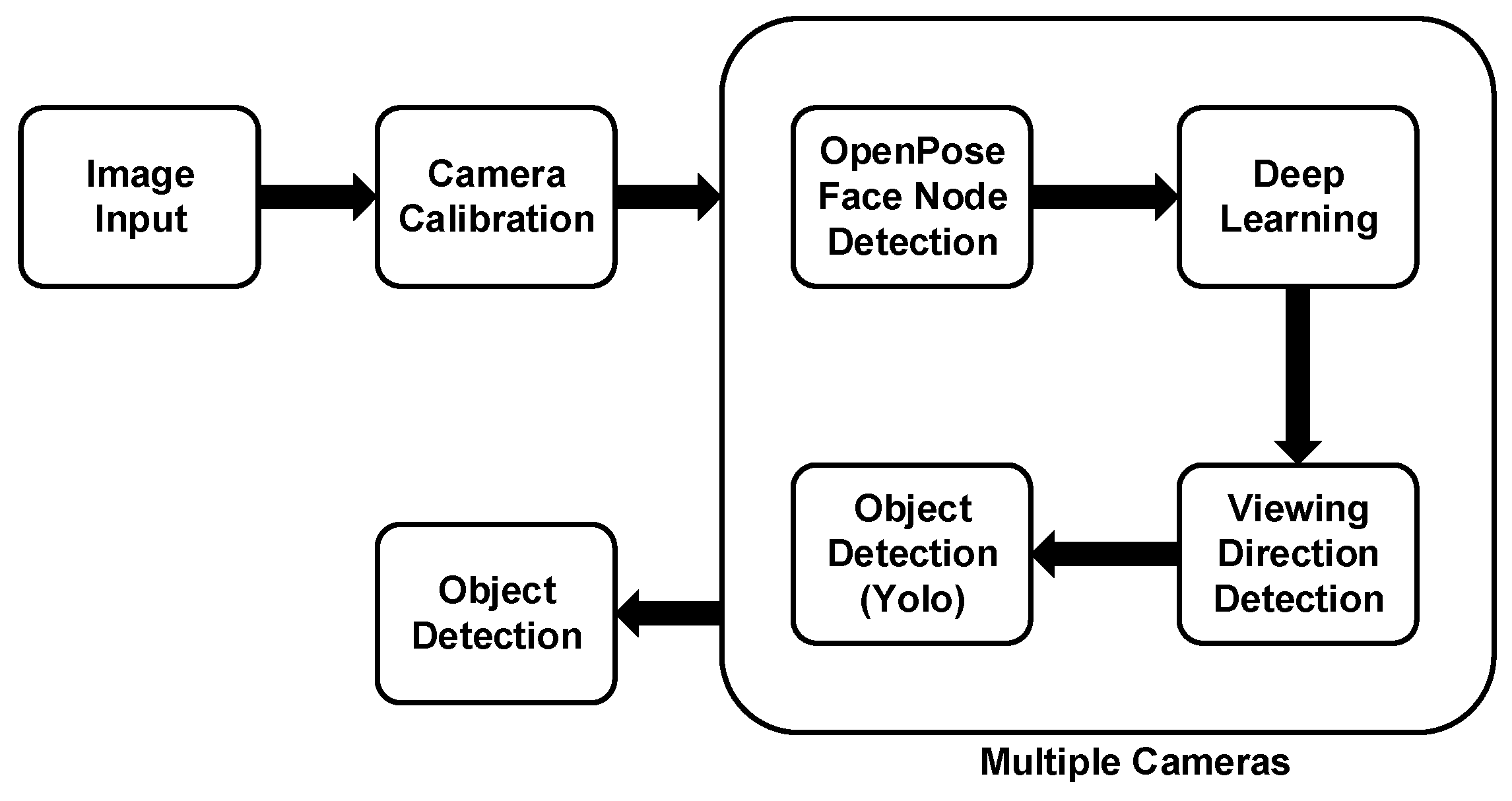
We summarize this research method as follows (Figure 1). After using OpenPose to capture the nodes of the person’s face, we established a deep learning network for sight training. After that, we used the YOLO object detection model and combined the models to calculate the objects in the person’s line of sight. With various cameras, we can estimate the objects in the line of view more accurately from multiple angles. Our method will reduce the cost of equipment and reduce battery consumption when combined with drones.

Figure 1.
Flowchart of long-distance viewing direction recognition.
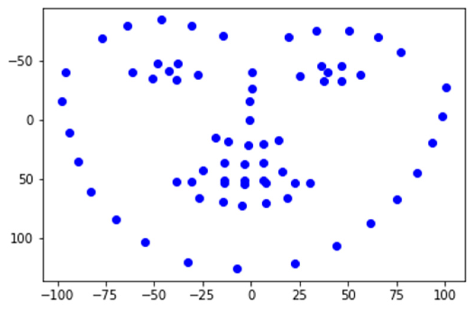
We used the OpenPose model to capture facial nodes. The reason for using the face nodes is that the face nodes will not have too much distortion under normal conditions, are suitable for use on most people, regardless of gender and age, and can roughly maintain the shape and characteristics of the face. There are 70 nodes (numbered 0 to 69) (Figure 2a), and we show the actual test in Figure 2b.
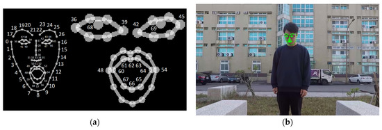
Figure 2.
(a) OpenPose face node numbers [24]; (b) face node test.
Convert the coordinates of each face point to the coordinate point (Equation (1)) centered on the nose node (point number 30) of the face nodes, where w is the image width, and h is the image height (,) The coordinates of the face nodes are centered on the upper left corner of the image. () is the face node centered on the nose node, as shown in the left image to the right picture of Figure 3.
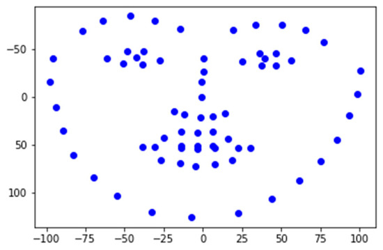
Figure 3.
Taking the nose node as the center node.
Take the straight-line distance between all the converted coordinates and the nose node, and then divide the straight-line distance by the straight-line distance from the nose node (point number 30) to the chin node (point number 8) for normalization (Equation (2)). Thus, the standardized data can avoid the error caused by the distance between the person and the shooting lens.
3. Deep Learning Network Construction
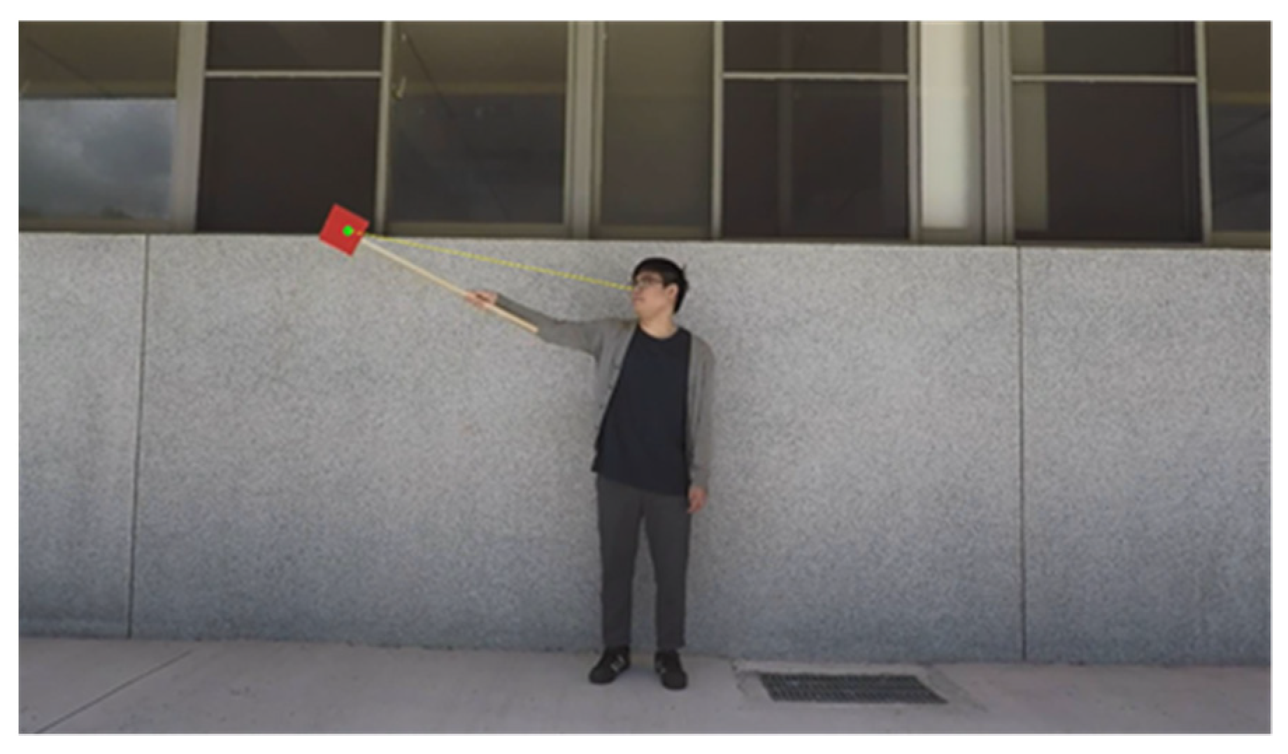
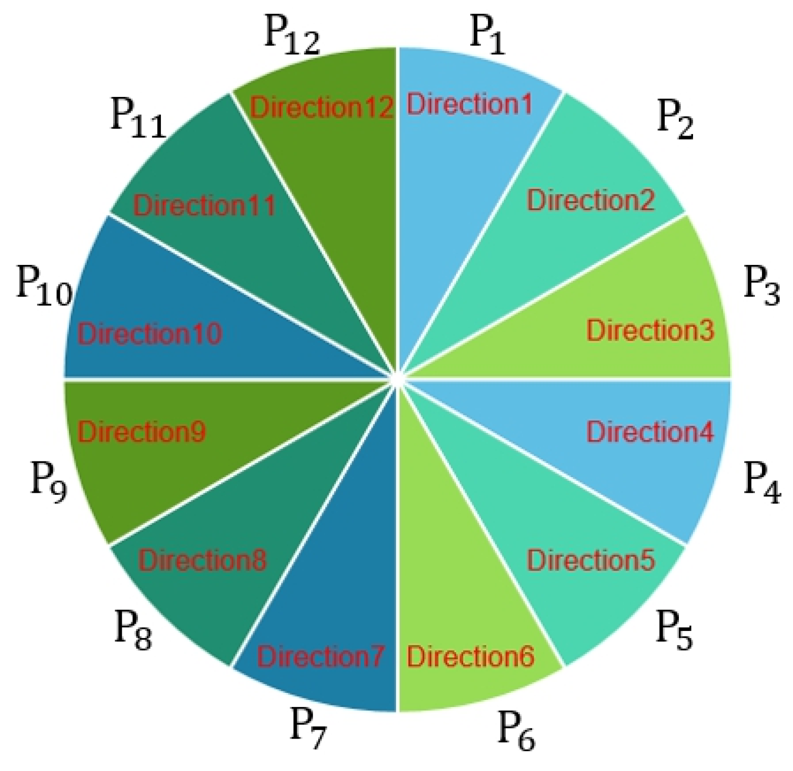
After using OpenPose to grab the face nodes, we used the Keras deep learning framework, built the neural network, and used Softmax classification at the end. We constructed the neural network to train the sight detection model with Input Layer Dimension = 70 and Output Layer Dimension = 12. There were nine hidden layers, where the first layer had a dimension of 140, and the other dimensions were 280. We labeled each as follows. We computed the center of the red paper gravity points to the nose node (Figure 4). We considered the straight-line slope (S) as P categories (Equation (3)) (Figure 5), where S was the radian. We then transformed the radian S into an angle and divided by the number of categories of P; is the label of each group of (Equation (4)).
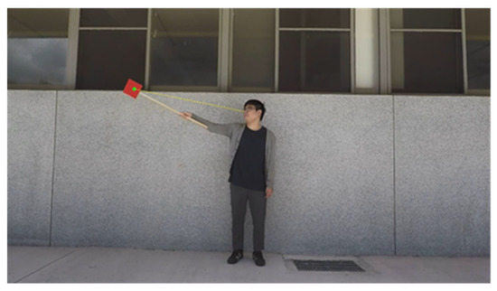
Figure 4.
The line from the nose node and the red paper center.
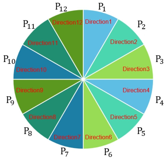
Figure 5.
Direction class.
After capturing the OpenPose face node, there are many parameters in the established neural network classifier that can be adjusted to achieve higher accuracy. This study will select Hinge Error and Cross-Entropy from the loss function for the experiment. Among them, Hinge Error is the maximum-margin method commonly used in Support Vector Machine (SVM) which is a kind of unilateral error and has no negative value (Equation (5)). Cross Entropy’s method is that the closer the actual value is to the predicted value of the model, the smaller the loss function, and conversely, the gap is enormous (Equation (6)).
The optimization function uses the Adam method. In the change of the learning rate, the Adam method will make the parameter update more stable, which is the most commonly used optimization function. We used AdaMax and Nadam for experiments. We used Relu as the activation function in the hidden layer since Relu has fast calculation speed and fast convergence speed. Because there is no complicated exponential operation, such as (Equation (7)), the activation function of the final output layer uses the Softmax (Equation (8)) for multi-classification.
Then, we used the line segments from the point () to the point () and from point () to point () to represent the viewing direction (Equation (9)).
Usually, it is hard to determine whether the person is in front of the object or the person’s back with only a single lens. Therefore, the character may be in front of the object, but the object is within the viewing direction. Consequently, we can use multiple lenses to shoot people, and after collecting the objects from various lenses, we can filter out the proper objects.
4. Experimental Results and Discussion
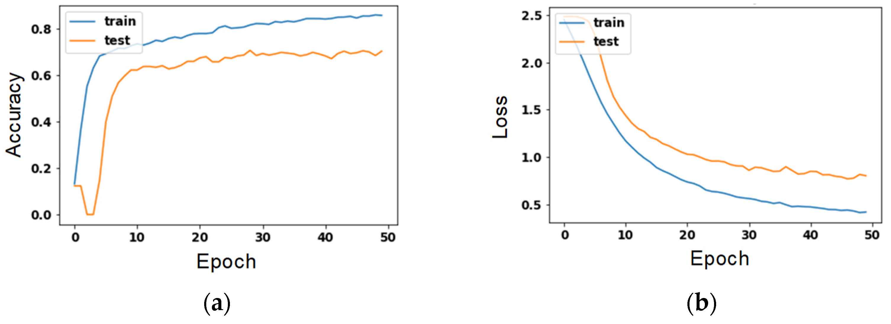
We conducted experiments for each step in the research method, tested the method’s ability, and analyzed the data after collating the data to improve the accuracy of the neural network and the model’s reliability. We used the experiment parameters and selected the Hinge Error and Cross-Entropy as the loss function. The optimization function is Adam, AdaMax, and Nadam. For experimental results, for example, the highest accuracy is the combination of the loss function Cross-Entropy and Adam’s optimization function (Table 1).

Table 1.
Accuracy for different parameters.
Figure 6 is a parameter diagram of the number of training times for the combination with the highest accuracy. The left axis shows the number of training times, and the Y-axis shows the accuracy rate. On the right, the X-axis is the number of training sessions, and the Y-axis is the loss.
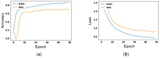
Figure 6.
Value of training times for the combination with the highest accuracy. (a) accuracy’s change to each epoch; (b) loss’s change to each epoch.
5. Testing of the Direction Detection Model
We had seven human bodies volunteer to test the model’s credibility after the neural network training, not for testing.
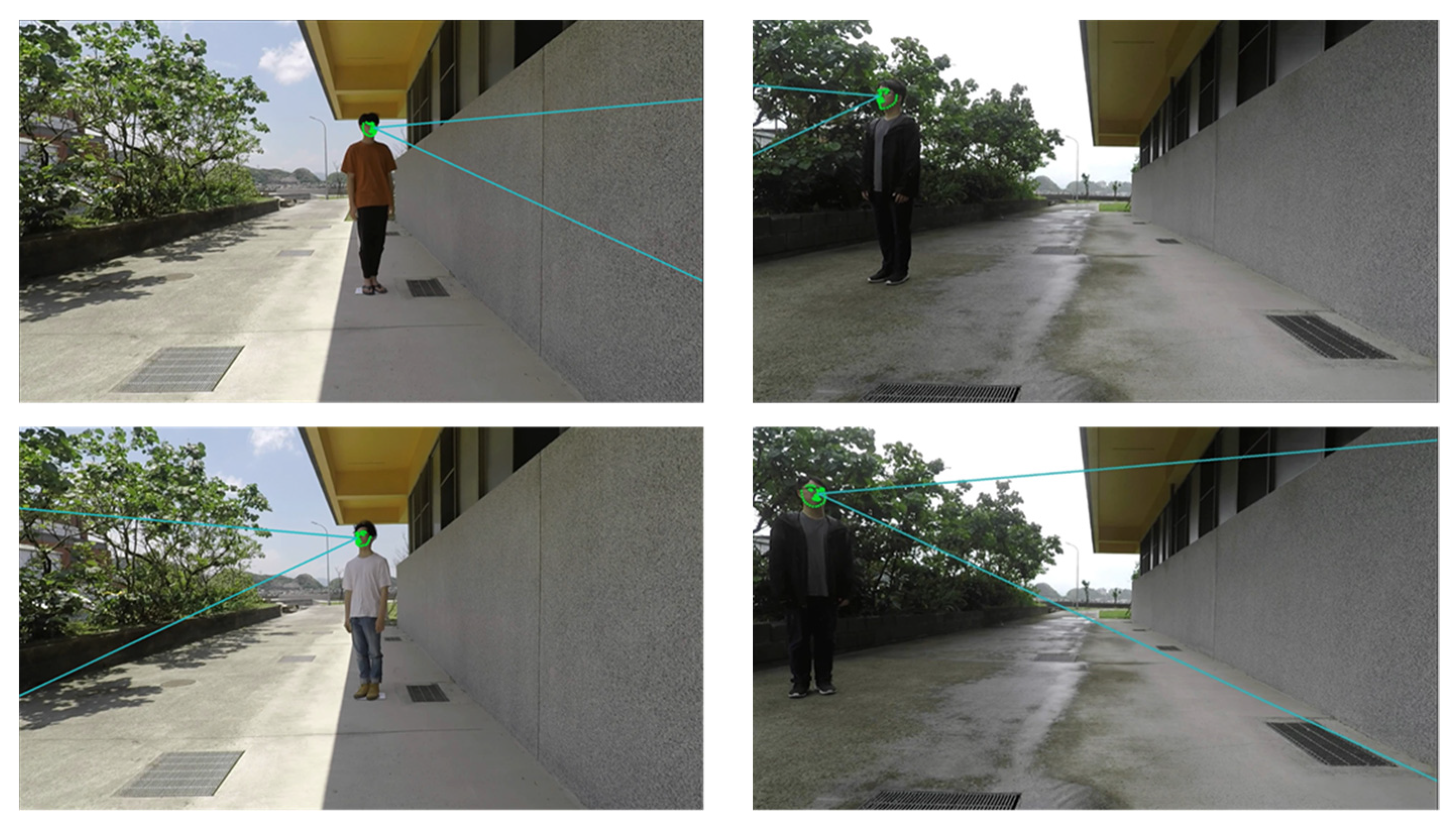
When the human body is in the center of the screen, we find that the visual direction detection model can also calculate the visual direction of different human bodies (Figure 7). The effective distance is greater than the previous visual direction detection methods. When the person is at the edge of the screen, the sharpness of the edge image decreases. However, when the face nodes are still valid, the direction detection model can also calculate the direction of the person’s view. Therefore, we believe that whether the person’s perspective can be successfully detected depends on whether the face image node is recognized. Since we have performed wide-angle distortion correction in the set direction of GoPro, even when the portrait is at the edge of the screen, the face nodes do not deform. Therefore, under the condition that the face nodes can be detected, the person’s perspective can be recognized at any screen position.
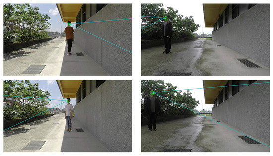
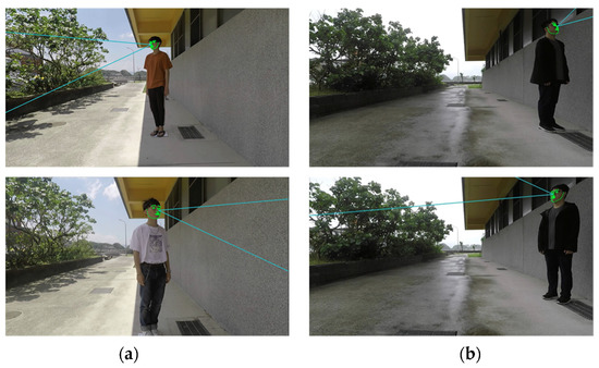
Figure 7.
Predicting the direction of the person’s viewing direction. (a) The human body is at the center of the screen; (b) the human body is at the edge of the screen.
5.1. OpenPose Detection Distance Test
The accuracy of the face nodes captured by OpenPose has the most significant impact on the factors that may affect the detection direction. Hence, we used OpenPose to capture face nodes and then used each point of the face midpoint vector of the nose. Finally, we used the normalized average value as the comparison value, and the results are as follows.
As shown in Figure 8, the X-axis is the distance (centimeter), and the Y-axis is the average value of each point of the face and the nose midpoint vector normalized. From the figure, we find that the displacement of the face nodes starts at about 6 m, which deviates from the actual face contour, and the deviation becomes more significant and more prominent after 6 m. Next, we look at the weights of face nodes (Figure 9), where the X-axis is the distance (cm), and the Y-axis is the average weight of all face nodes. Again, we can find that after 6 m, the decrease in weight increases significantly. In this experimental environment (1920 × 1080 pixels), the size of a face 6 m away from the lens is about 32 × 32 pixels. Therefore, we think that the resolution of the face may be too small, resulting in lower recognition of the face.
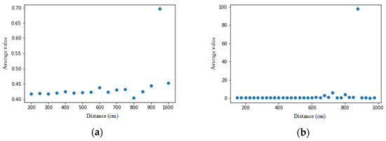
Figure 8.
Comparison of normalized face nodes for two persons. The X-axis is the distance from the camera, and the Y-axis is the average value for each face point to the nose vector after normalization on (a) person 1; (b) person 2.
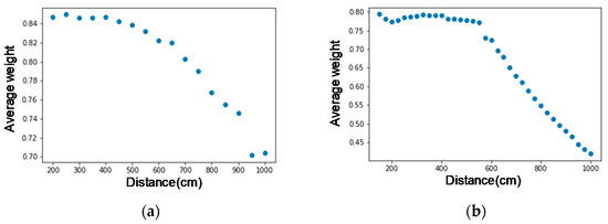
Figure 9.
Average node weights for two persons. The X-axis is the distance from the camera, and the Y-axis is the average weight of all face nodes on (a) person 1; (b) person 2.
In the application of object recognition, if the image of the object itself is too small, it will also resolve the object image too low and difficult to recognize. Therefore, we hope that the distance between the camera and the object is as far as possible considering gaze recognition. On the other hand, object recognition hopes that the object is as close as possible. The above two things are difficult to consider in the image, and they are also topics that we will study in the future.
5.2. OpenPose Detection Angle Test
This experiment tests whether OpenPose can accurately capture the face nodes under the condition of tilting the face. The larger the shooting angle, the more objects can appear on the screen, and we can screen out more accurately the objects in the viewing direction. The following are the tests from various angles.
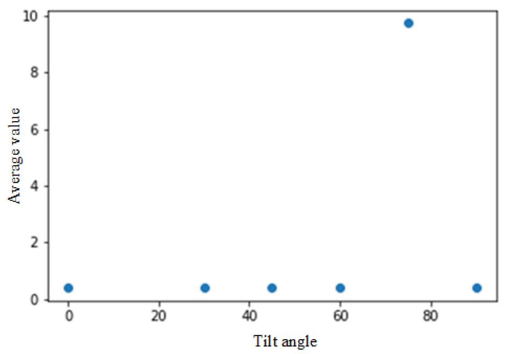
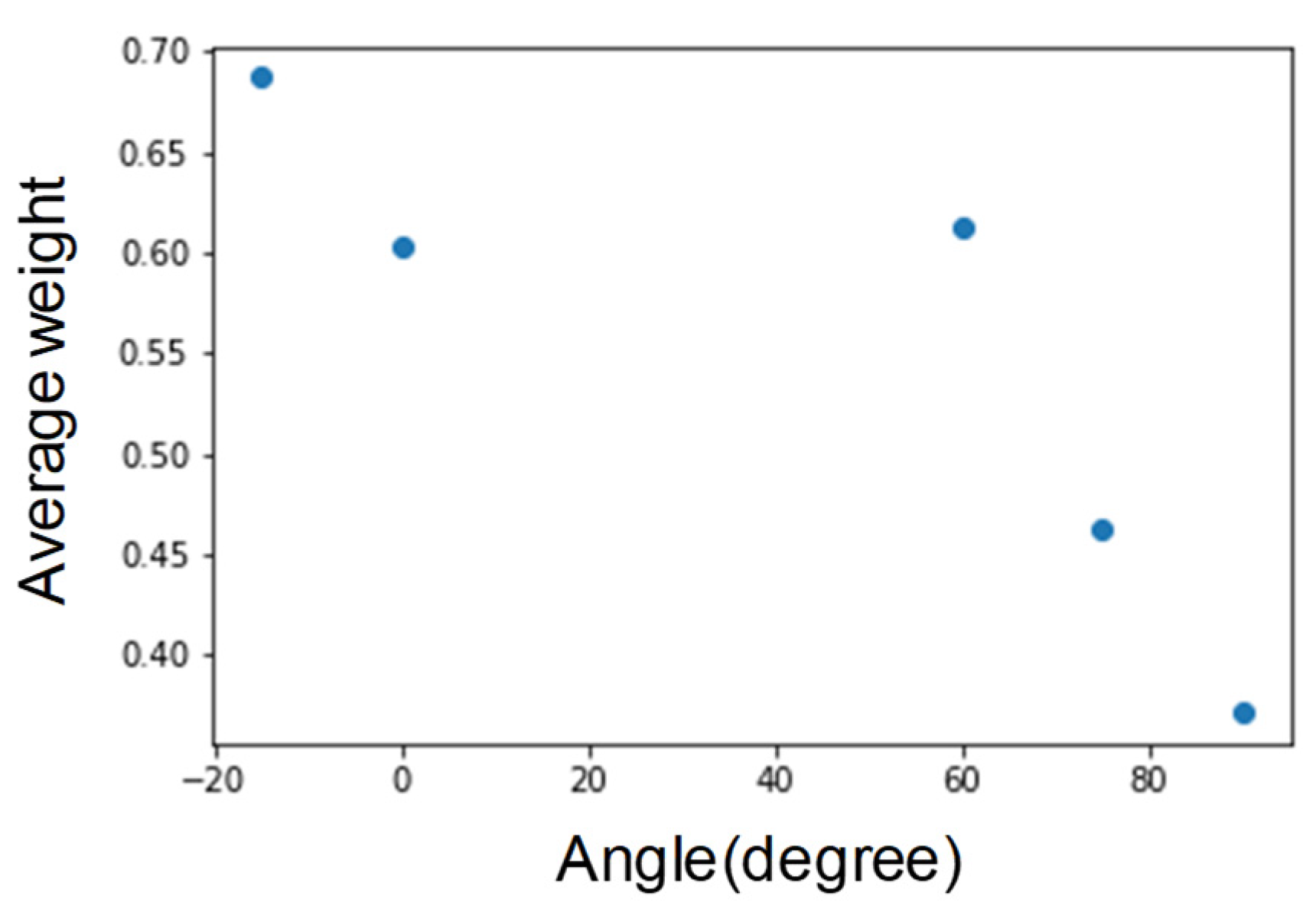
With testing the tilt of the face (Figure 10), although there is an offset at about 60 degrees, we can still grab the face nodes. However, under conditions more significant than 60 degrees, most of the face nodes disappear. As shown in Figure 11, an angle greater than 60 degrees has poor results. Therefore, the limit for judging the inclined face node is about 60 degrees.
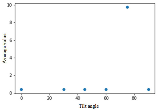
Figure 10.
Comparison of face nodes after normalization. The Y-axis is the average value of the normalized vectors from face points to nose.
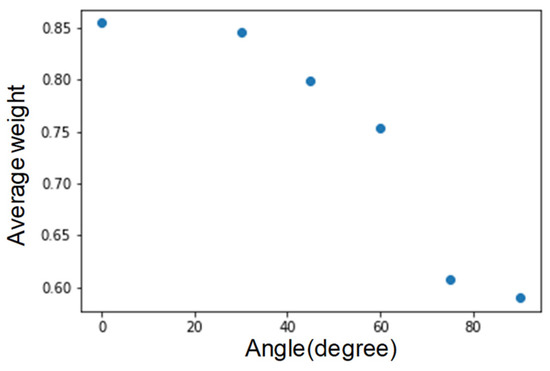
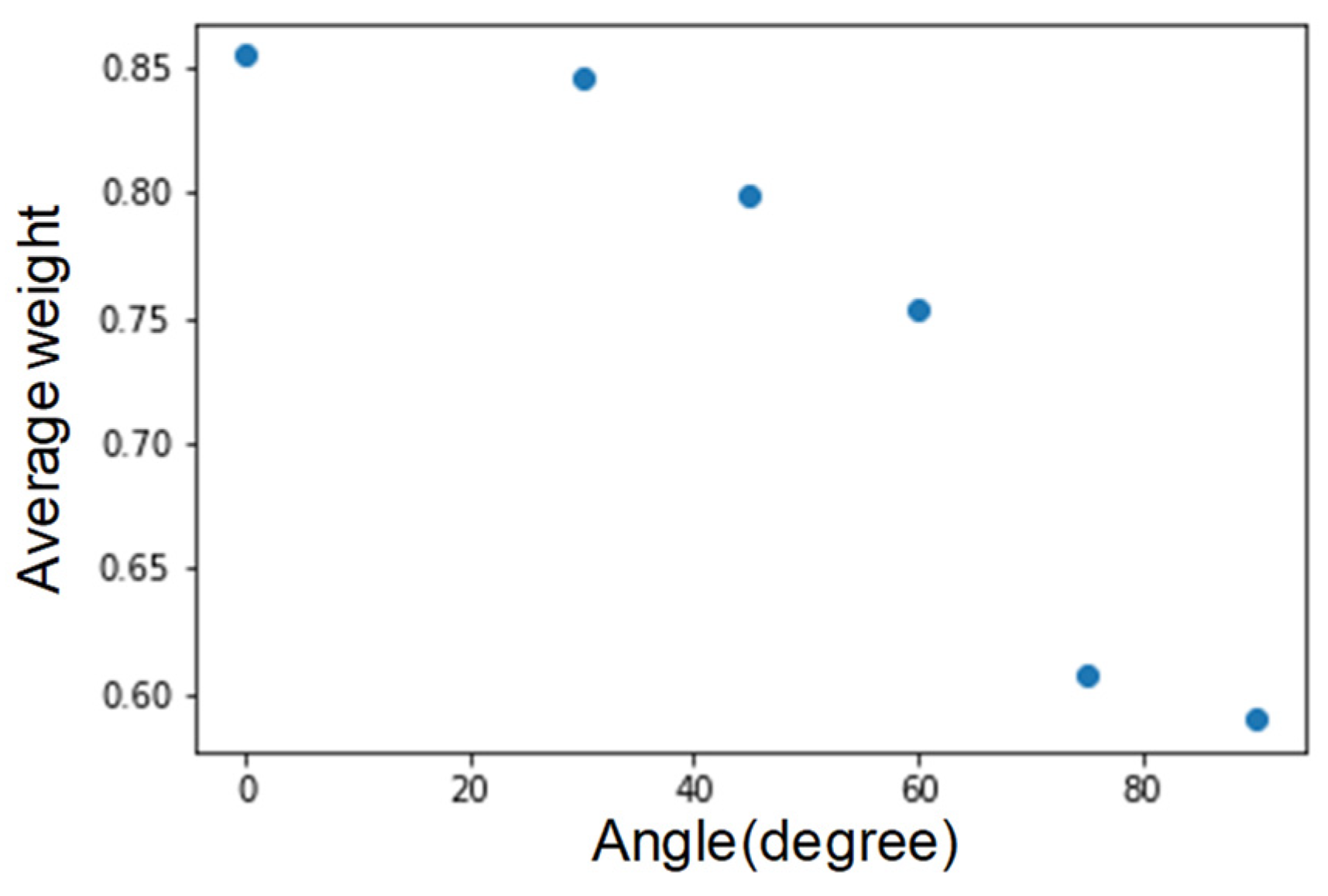
Figure 11.
Average graph of face node weights.
From Figure 12, we find that the vertical inclination angle is above 60 degrees. We infer that it is because the weight decreases and the face nodes cannot accurately capture. Hence, limiting the face nodes to capture the vertical inclination angle is approximately 60 degrees.
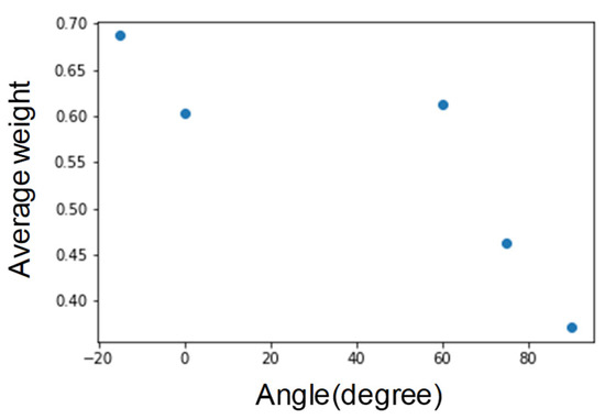
Figure 12.
Average weight vertical inclination.
Since the face rotates more than 60 degrees, it is difficult for the two eyes to appear in the image simultaneously. Therefore, in only half of the face, the detection error of the angle of view should also be more significant. On the other hand, the viewing angle range would also be a fan-shaped area on the rotation direction side with the eye as the center. However, when there are images of faces in different directions, it may be possible to obtain a more positive image with other cameras, thereby estimating the person’s gaze.
5.3. Viewing Direction Detection Model with Object Detection
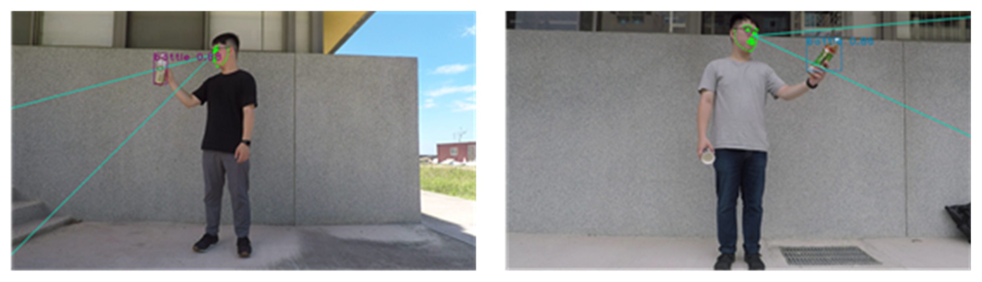
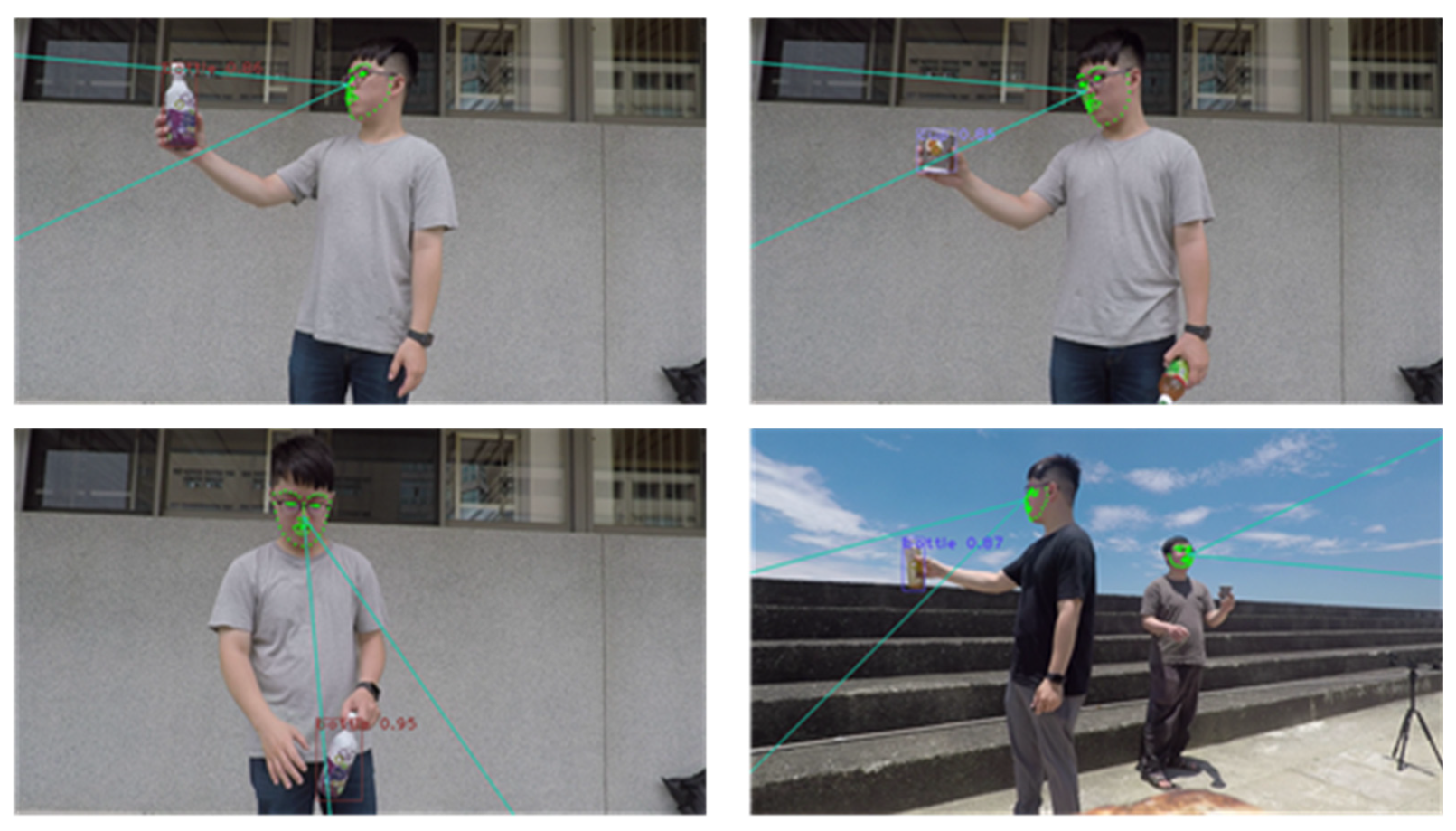
Next, combine the trained viewing direction detection model with the object detection model to filter out the objects that the person in the image is observing (Figure 13).


Figure 13.
Viewing object detection.
We can find that the estimated visual distance of the person, combined with the object detection model, can filter out objects that are not in the visible spectrum, leaving items in the visible distance, and it also applies to multiple people. The advantage of this study over traditional methods is that it can detect the line of sight at long distances. Measurement combined with viewing direction detection can infer what the human body is observing. It is also impossible to catch multiple people at the same time by traditional methods.
6. Conclusions
Recently, methods of viewing direction detection use eye trackers and lenses. Because the eye tracker can accurately determine the direction of the line of sight in the effective distance, head rotation cannot be affected. However, the effective detection distance is only about 50 to 80 cm. In this study, we used an image of a human head to estimate the direction of view, which differs from the previous method. This study uses the human skeleton node detection technology OpenPose, a visual detection model trained after grabbing face nodes so that the body nodes can have more room to play. It solves the problem of distance limitation of traditional viewing direction detection technology. Therefore, we can use it further and adapt to different environmental light sources. It is also lower in cost than previous technologies. Combining the viewing direction detection model and object detection technology can provide more helpful information from the image. According to the experiment results, we need to judge most of the face nodes in the direction of sight detection in terms of research limitations. Therefore, if the head can be rotated freely without degree limitation, it is crucial to capture the face nodes. In the future, it may be possible to add the direction of the body to screen for possible viewing directions.
Author Contributions
Formal analysis, Y.-S.T.; funding acquisition, S.-S.L.; methodology, Y.-S.T.; project administration, Y.-Z.H.; software, N.-C.C. All authors have read and agreed to the published version of the manuscript.
Funding
This research was funded by Ministry of Science and Technology, grant number MOST 110-2634-F-009-018-, MOST 109-2221-E-008-059-MY3, MOST 110-2221-E-019-052-MY3, MOST 108-2221-E-019-038-MY2, MOST 110-2218-E-002-032-MBK, MOST 110-2221-E-019 -051 -, MOST 109-2622-E-019 -010 -, MOST 109-2221-E-019 -057 -, MOST 110-2634-F-019 -001 -, MOST 110-2634-F-008 -005 -, MOST 110-2221-E-019-052-MY3, and MOST 108-2221-E-019-038-MY2.
Institutional Review Board Statement
Not applicable.
Informed Consent Statement
Not applicable.
Data Availability Statement
Not applicable.
Acknowledgments
Thanks for Pervasive Artificial Intelligence Research Labs (PAIR), National Yang Ming Chiao Tung University, Taiwan, support.
Conflicts of Interest
The authors declare no conflict of interest.
References
- Girshick, R.; Donahue, J.; Darrell, T.; Malik, J. Rich feature hierarchies for accurate object detection and semantic segmentation. In Proceedings of the IEEE Conference on Computer Vision and Pattern Recognition, Columbus, OH, USA, 23–28 June 2014; pp. 580–587. [Google Scholar]
- Girshick, R. Fast r-cnn. In Proceedings of the IEEE International Conference on Computer Vision, Santiago, Chile, 7–13 December 2015; pp. 1440–1448. [Google Scholar]
- Ren, S.; He, K.; Girshick, R.; Sun, J. Faster R-CNN: Towards real-time object detection with region proposal networks. In Proceedings of the Advances in Neural Information Processing Systems, Montreal, QC, Canada, 7–12 December 2015; pp. 91–99. [Google Scholar]
- Redmon, J.; Divvala, S.; Girshick, R.; Farhadi, A. You only look once: Unified, real-time object detection. In Proceedings of the IEEE Conference on Computer Vision and Pattern Recognition, Las Vegas, NV, USA, June 27–30 2016; pp. 779–788. [Google Scholar]
- Redmon, J.; Farhadi, A. YOLOv3: An incremental improvement (2018). arXiv 2018, arXiv:1804.02767. [Google Scholar]
- Liu, W.; Anguelov, D.; Erhan, D.; Szegedy, C.; Reed, S.; Fu, C.-Y.; Berg, A.C. Ssd: Single shot multibox detector. In Proceedings of the European Conference on Computer Vision, Amsterdam, The Netherlands, 8–16 October 2016; pp. 21–37. [Google Scholar]
- Noori, F.M.; Wallace, B.; Uddin, M.Z.; Torresen, J. A robust human activity recognition approach using openpose, motion features, and deep recurrent neural network. In Scandinavian Conference on Image Analysis; Springer: New York, NY, USA, 2019; pp. 299–310. [Google Scholar]
- Dollár, P.; Rabaud, V.; Cottrell, G.; Belongie, S. Behavior recognition via sparse spatio-temporal features. In Proceedings of the 2005 IEEE International Workshop on Visual Surveillance and Performance Evaluation of Tracking and Surveillance, Beijing, China, 15-16 October 2005; pp. 65–72. [Google Scholar]
- Ledezma, A.; Zamora, V.; Sipele, Ó.; Sesmero, M.P.; Sanchis, A. Implementing a Gaze Tracking Algorithm for Improving Advanced Driver Assistance Systems. Electronics 2021, 10, 1480. [Google Scholar] [CrossRef]
- Yoon, H.S.; Park, K.R. CycleGAN-Based Deblurring for Gaze Tracking in Vehicle Environments. IEEE Access 2020, 8, 137418–137437. [Google Scholar] [CrossRef]
- Syed, R.; Collins-Thompson, K.; Bennett, P.N.; Teng, M.; Williams, S.; Tay, D.W.W.; Iqbal, S. Improving learning outcomes with gaze tracking and automatic question generation. In Proceedings of the Web Conference 2020, Taipei Taiwan, 20–24 April 2020; pp. 1693–1703. [Google Scholar]
- Whitmire, E.; Trutoiu, L.; Cavin, R.; Perek, D.; Scally, B.; Phillips, J.; Patel, S. EyeContact: Scleral coil eye tracking for virtual reality. In Proceedings of the 2016 ACM International Symposium on Wearable Computers, Heidelberg, Germany, 12–16 September 2016; pp. 184–191. [Google Scholar]
- Punde, P.A.; Jadhav, M.E.; Manza, R.R. A study of eye tracking technology and its applications. In Proceedings of the 2017 1st International Conference on Intelligent Systems and Information Management (ICISIM), Maharashtra, India, 5–6 October 2017; pp. 86–90. [Google Scholar]
- Koposov, D.; Semenova, M.; Somov, A.; Lange, A.; Stepanov, A.; Burnaev, E. Analysis of the reaction time of esports players through the gaze tracking and personality trait. In Proceedings of the 2020 IEEE 29th International Symposium on Industrial Electronics (ISIE), Delft, The Netherlands, 17–19 June 2020; pp. 1560–1565. [Google Scholar]
- Jyotsna, C.; Amudha, J.; Rao, R.; Nayar, R. Intelligent gaze tracking approach for trail making test. J. Intell. Fuzzy Syst. 2020, 38, 6299–6310. [Google Scholar] [CrossRef]
- Kothari, R.S.; Chaudhary, A.K.; Bailey, R.J.; Pelz, J.B.; Diaz, G.J. EllSeg: An Ellipse Segmentation Framework for Robust Gaze Tracking. IEEE Trans. Vis. Comput. Graph. 2021, 27, 2757–2767. [Google Scholar] [CrossRef] [PubMed]
- Lee, K.-F.; Chen, Y.-L.; Yu, C.-W.; Chin, K.-Y.; Wu, C.-H. Gaze tracking and point estimation using low-cost head-mounted devices. Sensors 2020, 20, 1917. [Google Scholar] [CrossRef] [PubMed]
- Sewell, W.; Komogortsev, O. Real-time eye gaze tracking with an unmodified commodity webcam employing a neural network. In Proceedings of the CHI’10 Extended Abstracts on Human Factors in Computing Systems, Atlanta, GA, USA, 10–15 April 2010; pp. 3739–3744. [Google Scholar]
- Burova, A.; Mäkelä, J.; Hakulinen, J.; Keskinen, T.; Heinonen, H.; Siltanen, S.; Turunen, M. Utilizing VR and gaze tracking to develop AR solutions for industrial maintenance. In Proceedings of the 2020 CHI Conference on Human Factors in Computing Systems, Honolulu, HI, USA, 25–30 April 2020; pp. 1–13. [Google Scholar]
- Hennessey, C.; Noureddin, B.; Lawrence, P. A single camera eye-gaze tracking system with free head motion. In Proceedings of the 2006 Symposium on Eye tracking Research & Applications, San Diego, CA, USA, 27–29 March 2006; pp. 87–94. [Google Scholar]
- Bao, Y.; Cheng, Y.; Liu, Y.; Lu, F. Adaptive feature fusion network for gaze tracking in mobile tablets. In Proceedings of the 2020 25th International Conference on Pattern Recognition (ICPR), Milan, Italy, 10–15 January 2021; pp. 9936–9943. [Google Scholar]
- Liu, X.; Liang, W.; Wang, Y.; Li, S.; Pei, M. 3D head pose estimation with convolutional neural network trained on synthetic images. In Proceedings of the 2016 IEEE International Conference on Image Processing (ICIP), Phoenix, AZ, USA, 25–28 September 2016; pp. 1289–1293. [Google Scholar]
- Zhang, X.; Sugano, Y.; Fritz, M.; Bulling, A. Appearance-based gaze estimation in the wild. In Proceedings of the IEEE Conference on Computer Vision and Pattern Recognition, Boston, MA, USA, 7–12 June 2015; pp. 4511–4520. [Google Scholar]
- Cao, Z.; Hidalgo, G.; Simon, T.; Wei, S.-E.; Sheikh, Y. OpenPose: Realtime multi-person 2D pose estimation using Part Affinity Fields. IEEE Trans. Pattern Anal. Mach. Intell. 2019, 43, 172–186. [Google Scholar] [CrossRef] [PubMed] [Green Version]
- Wei, S.-E.; Ramakrishna, V.; Kanade, T.; Sheikh, Y. Convolutional pose machines. In Proceedings of the IEEE conference on Computer Vision and Pattern Recognition, Las Vegas, NV, USA, 27–30 June 2016; pp. 4724–4732. [Google Scholar]
- Cao, Z.; Simon, T.; Wei, S.-E.; Sheikh, Y. Realtime multi-person 2d pose estimation using part affinity fields. In Proceedings of the IEEE conference on computer vision and pattern recognition, Honolulu, HI, USA, 21–26 July 2017; pp. 7291–7299. [Google Scholar]
- Simon, T.; Joo, H.; Matthews, I.A.; Sheikh, Y. Hand Keypoint Detection in Single Images Using Multiview Bootstrapping. CVPR 2017, 1, 2. [Google Scholar]


Publisher’s Note: MDPI stays neutral with regard to jurisdictional claims in published maps and institutional affiliations. |
© 2021 by the authors. Licensee MDPI, Basel, Switzerland. This article is an open access article distributed under the terms and conditions of the Creative Commons Attribution (CC BY) license (https://creativecommons.org/licenses/by/4.0/).