Article

Development of a Magnetic Fluid Heating FEM Simulation Model with Coupled Steady State Magnetic and Transient Thermal Calculation

Faculty of Electrical Engineering and Computer Science, University of Maribor, Koroška Cesta 46, 2000 Maribor, Slovenia
*
Author to whom correspondence should be addressed.
Mathematics 2021, 9(20), 2561; https://doi.org/10.3390/math9202561
Submission received: 31 August 2021 / Revised: 8 October 2021 / Accepted: 11 October 2021 / Published: 13 October 2021
(This article belongs to the Section Mathematical Physics)

Abstract

:
Magnetic fluid hyperthermia has gained much attention in recent years due to its potential in cancer treatment. Magnetic fluid is a colloidal liquid made of nanoscale magnetic particles suspended in a carrier fluid. The properties of a commercial magnetic fluid consisting of maghemite (γ-Fe2O3) particles suspended in mineral oil were used in the scope of our research. The paper deals with a novel approach to the development of a magnetic fluid FEM model of a laboratory setup, with consideration of the electromagnetic steady state and thermal transient calculation soft coupling. Also, adjustment of the mathematical model was added in such a way that it enables a link between the magnetic and thermal calculations in commercial software. The effective anisotropy’s influence on the calculations is considered. The simulation was done for different magnetic field parameters. The initial temperature was also varied so that a direct comparison could be made between the simulation and the measurements. A good indicator of the accuracy of the simulation are the SAR values. The relative differences in SAR values were in the range from 4.2–24.9%. Such a model can be used for assessing the heating performance of a magnetic fluid with selected parameters. It can also be used to search for the optimal parameters required to design an optimal magnetic fluid.

1. Introduction

Magnetic fluid hyperthermia has gained much attention in recent years due to its potential in cancer treatment. Hyperthermia treatment should impair tumour cells without damaging the healthy surrounding tissue. In practice, the treatment involves heating the tumour region to the temperature range of 40–44 °C [1]. Therefore, it is essential to know the heating characteristics of the magnetic fluid. In addition to heating of the cells, it should be mentioned that there are other possible methods, like freezing the cells [2].
Magnetic fluid, also named ferrofluid, is a colloidal liquid made of nanoscale magnetic particles suspended in a carrier fluid. The particles are coated with a surfactant to prevent agglomeration. The properties of a commercial magnetic fluid consisting of maghemite (γ-Fe2O3) particles suspended in mineral oil were used in the scope of our research.
Experimentally, magnetic fluid heating characteristics are often measured using a method called the calorimetric method. There, the magnetic fluid is subjected to an alternating magnetic field, and the time dependence of the temperature is measured, as has been done in [3]. The heating characteristics of the magnetic fluids are usually represented with a parameter called the Specific Absorption Rate (SAR) in Watts per gram of magnetic nanoparticles (MNPs). The value of the SAR can be obtained directly from the time–temperature curve. The most straightforward approach in determining SAR is using the initial slope method, where the SAR is calculated from the initial slope of the time–temperature curve as:
SAR IS = c f ρ f m MNP Δ T Δ t i
Here, cf is the fluid’s specific heat, ρf is the density of the fluid, mMNP is the mass of the MNPs in the fluid and (ΔTt)i is the initial slope of the curve. This approach assumes that the heating process is adiabatic, or that cooling is negligible. It was used in the literature [1,4,5,6].
Due to the difficulties and time consumption in characterizing magnetic fluids experimentally, a numerical model was developed using the Finite Element Method (FEM). With this, it is possible to simulate the heating of the magnetic fluid in a calorimetric experiment environment and obtain results for magnetic fluids with different parameters much faster. It can also be used for the determination of magnetic fluid parameters for optimal heating.
Related work can be found in the literature. In the literature [7], the authors deal with the development of the analytical relationship and computations of power dissipation in magnetic fluid in an alternating magnetic field based on relaxation processes in the magnetic fluid. Similarly, article [8] presents a model based on relaxation processes to calculate magnetic losses and SAR based on the parameters of the magnetic fluid. The model was validated with the use of calorimetric measurements for different magnetic field amplitudes, frequencies and shapes. Article [9] deals with the determination of the temperature dependence of the heating power of the magnetic fluid. Temperature dependence was determined experimentally via magnetic measurements. The obtained curves were used in transient FEM analysis (using OPERA software) of the heating power. The results were compared with the measurements. Literature [10] deals with the development of a numerical model for estimating temperature distribution in a magnetic fluid system, validating it by analysis of the temperature distribution between experimental measurements and numerical analysis by FEM (using ABAQUS software, ABAQUS Inc., Palo Alto, CA, USA). Initially, experiments were conducted and the temperature increase was measured. For the obtained curves, Specific Loss Power (SLP) was determined and used for numerical modelling of the system. Many articles deal with numerical simulations calculating the heating of MNPs in cancer tissue using a heating model based on relaxation processes and Pennes bioheat equation [11,12,13,14,15,16]. Similarly, [17] deals with the numerical modelling of hypethermia using the Pennes model for heat transfer while using the Gaussian heat generation distribution proposed by [18]. In [19], heating of the MNPs was simulated using a stochastic Néel-Brown Langevin equation and Monte Carlo simulations. The results were compared with the calorimetric measurements results. In [20], a 2D axisymmetric model was developed in COMSOL using heat transfer equations and Navier-Stokes equations. For heating power, a temperature-dependent function was used, obtained via an optimization study. In [21], the efficiency of MNPs’ heating was investigated in the dependence of various magnetic fluid parameters, including particle size, shape, anisotropy, and the degree of aggregation or agglomeration of the particles. The aggregation of particles in magnetic fluids tends to be avoided, but can be useful in some treatment applications, like MRI-guided drug delivery, as demonstrated in [22,23,24]. While simulations of the heating of MNPs inside a tumour give important results, they do not, however, describe the intrinsic heating characteristic of the magnetic fluid. In the literature, mathematical models used to calculate the heating of the magnetic fluid are known. They are used to simulate heating of the MNPs in cancer tissue in [11,12,13,14,15,16]. For the laboratory setting, simulations in the literature use pre-measured heating results for heating power data, and simulate temperature distribution using the transient thermal calculations in [9,10], although to our knowledge, coupled magnetic and thermal simulations for the laboratory setting are missing. Therefore, our work focuses on the heating capabilities of a magnetic fluid in a laboratory setting using coupled steady state magnetic and transient thermal calculations for the simulation.
The main contributions of our work are:
  • Development of a magnetic fluid FEM model with consideration of electromagnetic and thermal soft coupling.
  • Adjustment of the mathematical model in such a way that it enables a link between the magnetic and thermal calculations in commercial software (Altair Flux3D).
  • Analysis of an effective anisotropy’s influence on the calculation results, and suggestions for correct setting of an effective anisotropy.
  • The correctness of the model and the correctness of the used parameters are confirmed with measurements.
The paper consists of seven Sections. The measurement system for measuring the heating characteristics of the magnetic fluid is described in Section 2. The mathematical model used for calculations is described in Section 3. The simulation model and simulation process are described in Section 4. The parameters for the mathematical model and material properties used in the simulation are described in Section 5 in Section 5.1 and Section 5.2, respectively. The results are gathered in Section 6, and conclusions are in Section 7.

2. Measurement System

The measurement system in our laboratory was used for the measuring (Laboratory for Applied Electromagnetics, Faculty of Electrical Engineering and Computer Science, University of Maribor). The measuring system is based on the calorimetric method for measuring magnetic fluids. It consists of a supply coil, a glass container with magnetic fluid, two field measuring coils and an optical temperature sensor. The supply coil is cooled with water. A function generator was used to generate the appropriate magnetic field, whose signal was then amplified with an amplifier. Additional capacitors were used to create an LC resonator with the supply coil. The setup is presented schematically in Figure 1.
The measurement procedure is as follows. First, a sinusoid signal is generated with the function generator. The signal is then amplified using a power amplifier. Beforehand, a suitable combination of capacitors is selected, to get the capacitance C that, combined with the supply coil’s inductance L, forms an LC resonator with the desired frequency f. This is the frequency set on the function generator. The supply coil generates an alternating magnetic field that heats the magnetic fluid positioned within the glass container inside the supply coil, as shown in Figure 1. The temperature is measured with an optical thermometer and the data are saved to the computer. Two measurement coils are used to measure the magnetic field in the magnetic fluid. The process of field measurement is described in [3] in more detail. From the obtained time–temperature curve at the measured magnetic field, SAR is calculated according to Equation (1).

3. Mathematical Model

To calculate the heating power of the magnetic fluid, a model based on the relaxation of magnetization was used, as described in [7,8]. There are two mechanisms of relaxation. One is relaxation by physical rotation of the MNP, known as Brownian relaxation. It is described by the relaxation time:
τ B = 3 V h η k B T   ,
where Vh is the hydrodynamic volume of the MNP, which takes into account the surfactant layer on top of the MNP, η is the viscosity of the carrier fluid, kB is the Boltzmann constant and T is the temperature in kelvin.
The other type of relaxation is the flipping of the magnetization of the MNP, known as Néelian relaxation. It is described by the relaxation time:
τ N = τ 0 e K eff V p k B T ,
where τ0 is the attempt time, Keff is the effective anisotropy constant of the MNP and Vp is the volume of the MNP. The effective relaxation time τ is given as:
1 τ = 1 τ N + 1 τ B .
Volumetric power dissipation in units of W/m3 is expressed as:
P = μ 0 π χ f H 2 ,
as was shown by Rosensweig in [7]. Here, µ0 is the permeability of free space, f frequency, H magnetic field strength amplitude and χ′′ the imaginary part of the complex susceptibility, expressed as:
χ = ω τ 1 + ω τ 2 χ 0 ,
where ω = 2πf is the angular frequency and χ0 is the equilibrium susceptibility:
χ 0 = χ i 3 α L α ,
with χi being initial susceptibility and L(α) the Langevin function and α the Langevin parameter. They are expressed as:
χ i = μ 0 ϕ M s 2 V p 3 k B T ,
L α = coth α 1 α ,
α = μ 0 M s H V p k B T ,
respectively. Ms represents the saturation magnetization of the bulk maghemite, and ϕ represents the volume fraction of MNPs.
To take into account the polydisperse nature of MNP sizes, the particles were divided into size groups. The heating power is the sum of the contributions of individual groups:
P = j = 1 M μ 0 π χ j f H 2 .
Here, index j represents the individual group and M is the number of groups. The size-dependent variables contained in χj are:
  • Volume fraction ϕj,
  • Particle diameter dj,
  • Particle volume Vpj and hydrodynamic volume Vhj,
  • Brown and Néel relaxation times τBj and τNj,
  • Langevin parameter αj.

4. Simulation

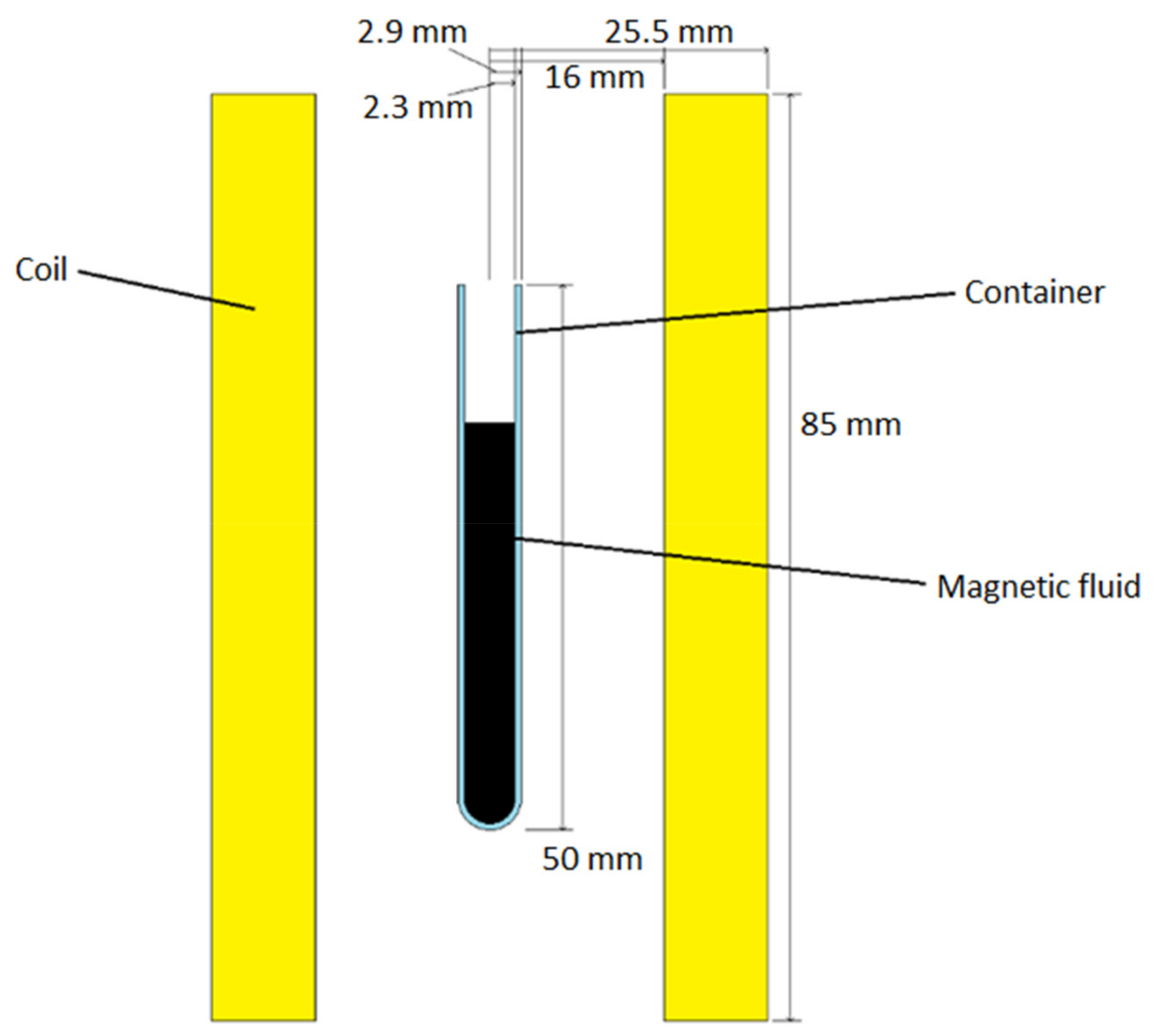
The Altair Flux 2018.1.2 software (Altair Engineering Inc., Troy, MI, USA) was used for the FEM simulation. The Flux3D was used for modelling, and Steady State AC Magnetic coupled with Transient Thermal option was used for solving, with the adjusted mathematical model used to couple them. The model that was built is presented schematically in Figure 2.
Coil information:
  • Length: l = 85 mm,
  • Inner diameter: di = 32 mm,
  • Outer diameter: do = 51 mm,
  • Number of turns: N = 36.
Magnetic fluid container information:
  • Length: le = 50 mm,
  • Outer diameter: de = 5.8 mm,
  • Glass thickness: dg = 0.6 mm.
For the simulation, based on previous information, a glass container was modelled with a marked height of the magnetic fluid.
A function offered by the Flux software named Infinite box was used for the boundary conditions. The technique uses a transformation to model an infinite domain. In our model, the infinite box was made by using two superimposed parallelepipeds. The faces of the outer parallelepiped represent the images of the infinity, where the magnetic field and its potential are equal to zero. The temperature at infinity is equal to the initial temperature of the problem. Afterwards, faces and volumes were built, and the problem was meshed. A circular non-meshed coil of a rectangular cross-section was used for the supply coil, with the dimensions shown in Figure 2.
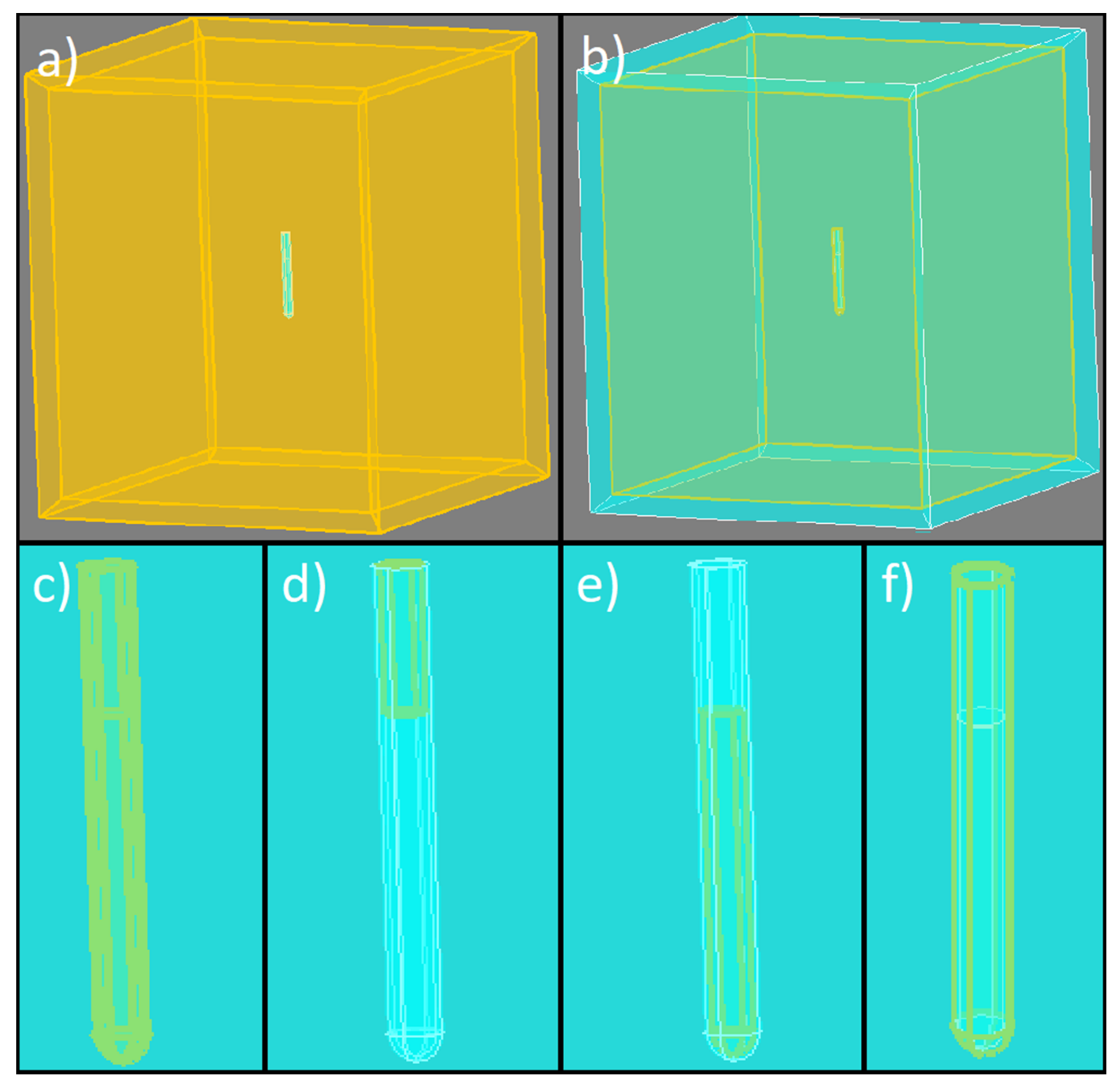
The regions were defined as the following: A non-active, or air region, in the infinity box region and the region between the infinity box and the container, glass for the container, magnetic fluid in the container below the magnetic fluid height marking, and air in the container above the marking. It is important to define the appropriate area for radiation and convection heat exchange to get correct results. For the presented problem, a face region with radiation and convection heat exchange was defined on the outer boundary of the container and on the upper face of the air inside the container. The regions are represented in Figure 3.
Equations (2)–(11) of the mathematical model were defined as spatial quantities in the scope of the Flux3D software environment. The model works as follows. The programme calculates the steady state magnetic conditions, and, after that, the heating power in the magnetic fluid, using Equations (2)–(11), initial temperature, magnetic field strength amplitude and frequency in the first time step. Based on the power, it calculates the temperature for the next time step. Then the process repeats for the new time step until the end of the simulation. The simulation flowchart is presented in Figure 4.
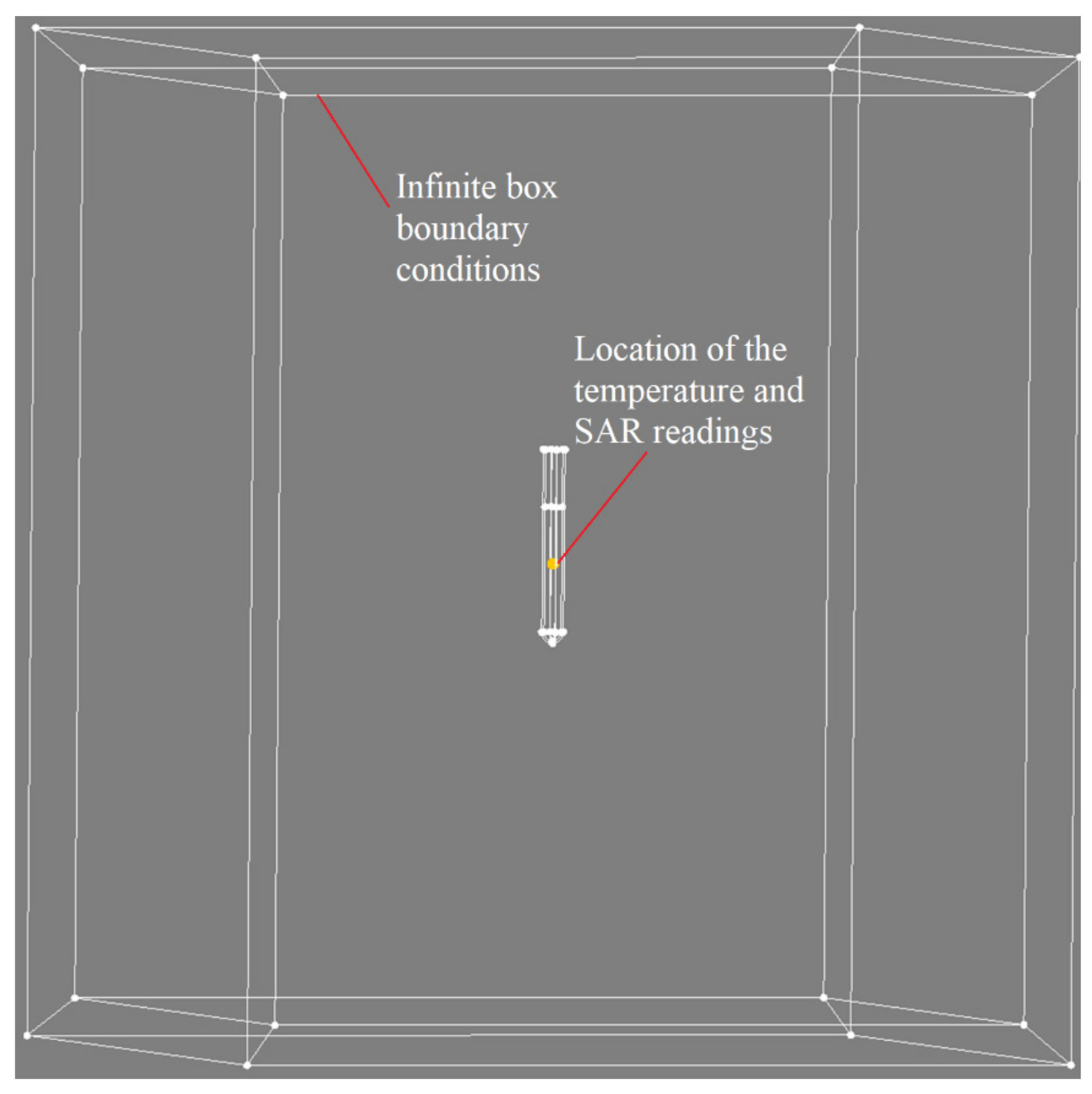
After the simulation ended, the average magnetic field strength amplitude in the whole magnetic fluid volume was calculated for each time step and the average value over time was taken. To get the temperature and SAR values, one point inside the magnetic fluid (the position of a temperature measuring sensor used in the case of measurement) was chosen to simulate the temperature measurement with a temperature probe. The location of the reading is shown in Figure 5, together with the Infinite box boundary conditions.
To get the value of SAR, we used equation [8]:
SAR = P ρ MNP .
Here, ρMNP represents the mass density of MNPs in the magnetic fluid, and is equal to ρMNP = ϕρm, where ρm = 4.9 g/cm3 is the density of the bulk maghemite. Equation (12) gives us a temperature-dependent function of SAR, the value of which at t = 0 s is directly comparable to the result of Equation (1).
The results given by this model were validated using the experimental measurement results obtained by the measurement system described in Section 2. It was done by comparing the time–temperature curves and initial SAR values from the simulations and measurements.

5. Selection of Parameters

In the modelling of the simulation, careful considerations must be made regarding parameters. Two types of parameters were present—the ones used in the mathematical model for the heating power calculation and the ones describing the magnetic and thermal properties of the materials.

5.1. Parameters Used for the Determination of the Software’s Spatial Quantities Determined with the Equations

In the mathematical model, the essential parameters are the volume fraction of MNPs ϕ with a corresponding size distribution, volumes Vp and Vh, the viscosity of carrier fluid η, attempt time τ0, effective anisotropy Keff and the magnetization of the bulk material Ms.

5.1.1. Volume Fraction ϕ

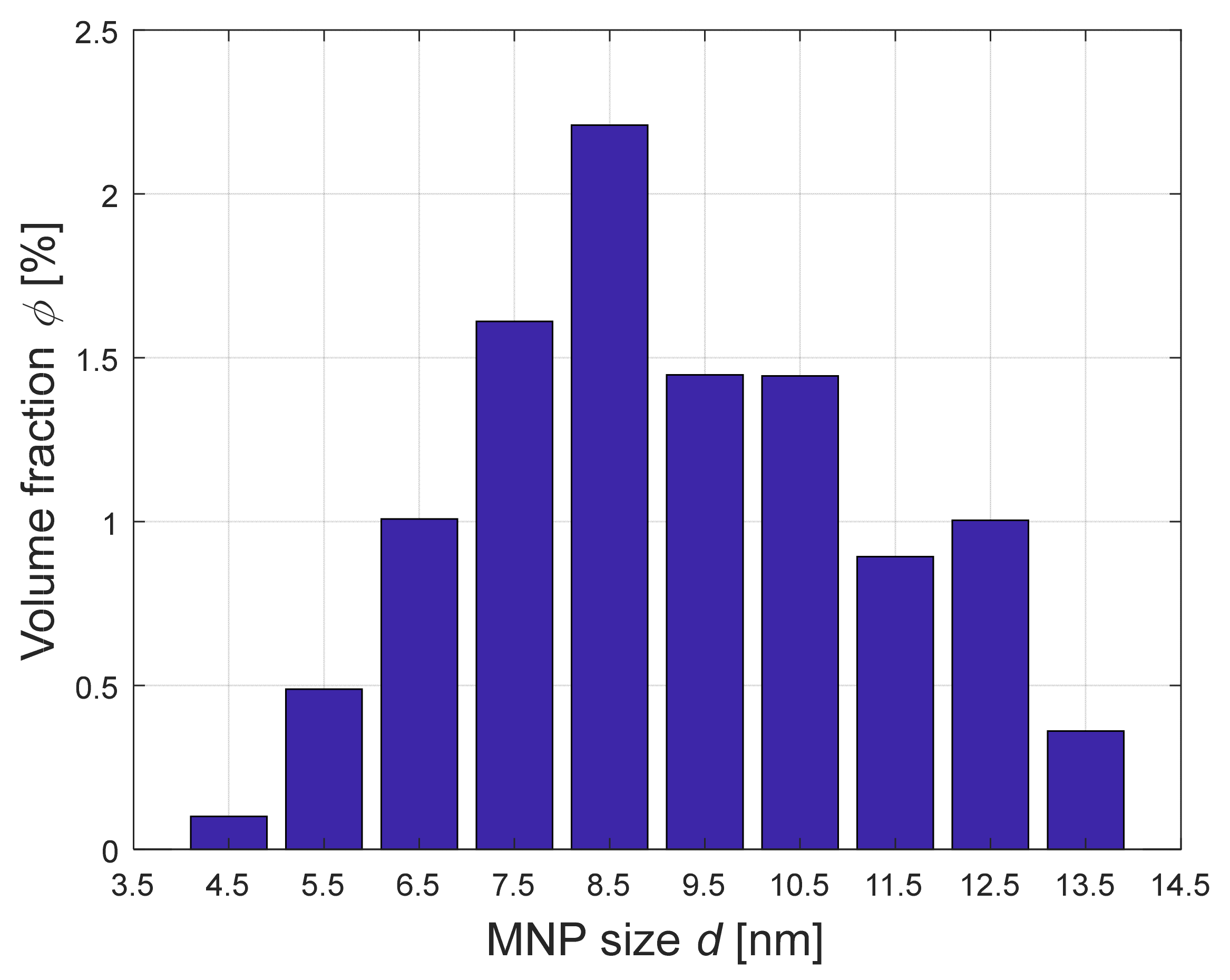
Volume fraction ϕ represents the content of MNPs in the magnetic fluid. For our sample of magnetic fluid, the volume fraction was measured at ϕ = 10.57%. Because the particles in the magnetic fluid are polydispersed, the particles were divided into ten groups of different sizes. The sizes and volume fractions are presented in Table 1 and Figure 6.

5.1.2. Volumes Vp and Vh

Volume Vp is the volume of one MNP. For the volume calculation, the particles were assumed to be spherical. Therefore, Vp can be estimated as Vp = π/6d3, where d is the diameter of the MNP. Volume Vh includes the surfactant layer s on the particle to the volume. The surfactant layer was estimated to be s = 1 nm, which adds 2 nm to the diameter of the particle.

5.1.3. Viscosity η

The following function was fitted to the data of temperature dependence of viscosity for mineral oil [26]:
η = A e B T + C .
Here, the fitting constants are: A = 3.4313 × 10⁻⁵ Pa s, B = 1248 K, C = −155.05 K.

5.1.4. Attempt Time τ0

The attempt time generally depends on the MNP material properties and, according to the literature [27], falls between 10−13 and 10−8 s. The value of 10−9 s was assumed, the same as in [8].

5.1.5. Effective Anisotropy Keff

This is one of the most critical parameters and one of the hardest to determine. Magnetic anisotropy describes the dependence of the magnetic properties of the material on the direction. It can be defined as the energy required to rotate the magnetization from the easy to the hard axis [28]. Anisotropy results from several contributions: Magnetocrystalline, shape and surface are some of them. The magnetic moment of the MNP generally coincides with the axis of the magnetic anisotropy [29]. Together with the MNP volume, the effective anisotropy coefficient describes the energy barrier the magnetization has to overcome to flip the direction (energy E = KeffV).
In the literature the measurements of maghemite MNPs effective anisotropy yielded different results in the range from 103 to 104 J/m3 [30,31,32]. To determine the value of Keff, the Stoner-Wolfarth model for shape anisotropy was used, described by equation (14) [33]. Using a Transmission Electron Microscope (TEM) picture, the aspect ratios r of the MNPs was determined to fall in the range between 1 and 2 for our sample, with the average being around 1.4.
K shape = 1 2 M s 2 N t N l .
Here, Nt and Nl are transverse and longitudinal demagnetizing factors, respectively. They are related by Nl + 2Nt = 2π. The longitudinal demagnetizing factor of a spheroid is calculated as:
N l = 2 π 1 ϵ 2 ϵ 3 ln 1 + ϵ 1 ϵ 2 ϵ ,
where ϵ = √(1 − 1/r2) is the eccentricity.
Combining shape anisotropy with magnetocrystalline anisotropy, which is 4.6 kJ/m3 for maghemite [7], the upper limit for the value of effective anisotropy becomes 17.3 kJ/m3, which was the value used in the simulation.

5.1.6. Saturation Magnetization of the Bulk Material Ms

As the name suggests, the parameter Ms represents the saturation magnetization of the bulk magnetic material. In our case, that was maghemite. The saturation magnetization of bulk maghemite is 400 kA/m [8].
The important parameters used for spatial quantities are collected in Table 2.

5.2. Basic Parameters Used in the Simulation Model for Material’s Properties’ Determination

The following material parameters were considered in the simulation model: Density, specific heat capacity, thermal conductivity or radiation and convection coefficients, and the magnetic permeability of glass for the container, air for the surrounding area, and magnetic fluid for the sample in the container. The parameters are:
For air:
  • Density [34]: ρ = 1.204 kg/m3,
  • Specific heat capacity [35] (Figure 7):
  • Relative magnetic permeability: μr = 1,
  • Thermal conductivity [36] (Figure 8):
For glass:
  • Density [37]: ρ = 2500 kg/m3,
  • Specific heat capacity [37]: c = 0.8 kJ/kgK,
  • Relative magnetic permeability: μr = 1,
  • Thermal conductivity [37]: λ = 0.8 W/mK,
For magnetic fluid:
  • Density: ρ = 1314.3 kg/m3,
  • Specific heat capacity: c = 1214.9 J/kgK,
  • For the magnetic permeability, the initial susceptibility was calculated using Equation (8) and converted into permeability using the equation:
    μ ri = 1 + χ i .
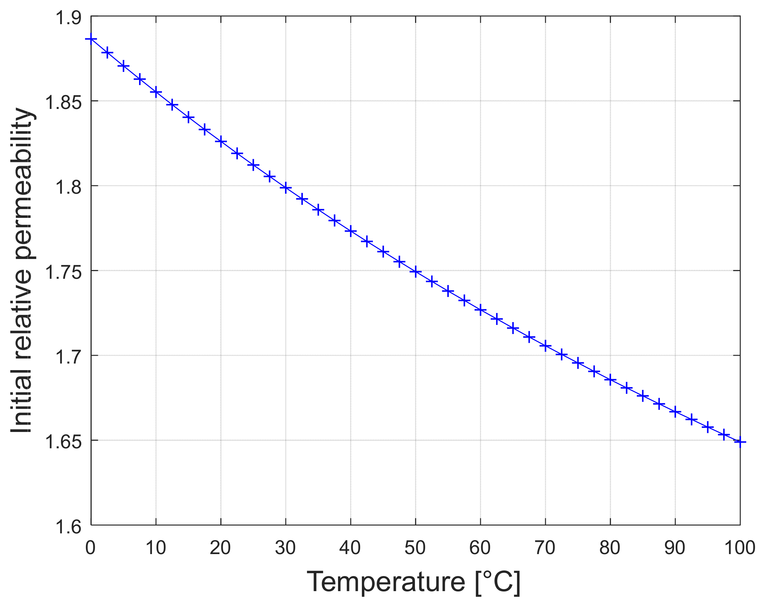
  • Initial magnetic permeability was then (Figure 9):
  • Saturation magnetization of the magnetic fluid: Mf = ϕMs = 42.3 kA/m,
  • The thermal conductivity was calculated with equation [38]:
    λ = λ f 1 + 2 β ϕ 1 β ϕ ,
    where λf is the thermal conductivity of the magnetic fluid, and β = (λpλf)/(λp + 2λf), with λp being the thermal conductivity of the MNP. For the thermal conductivity of the carrier fluid, the value of λf = 0.15 W/mK was estimated for mineral oil, taking literature [39] as a guide. For maghemite, the thermal conductivity falls in the range of 0.86–1.30 W/mK, according to [40]. For the value λp = 0.92 W/mK, using Equation (17), the magnetic fluid thermal conductivity was λ = 0.187 W/mK.
On the face region (Figure 3) around the container, the emissivity (value of 0.93) and absorption (value of 0.2) coefficients (for radiation), and convection coefficient (value of 10 W/m2K) were defined. These were used to simulate radiation and natural convection losses.

6. Results

The simulation was run for different magnetic field parameters (field strength and frequency). Also, the initial temperature was varied, so that a direct comparison could be done between the simulation results and the measurements.

6.1. Magnetic Field and Temperature Distribution

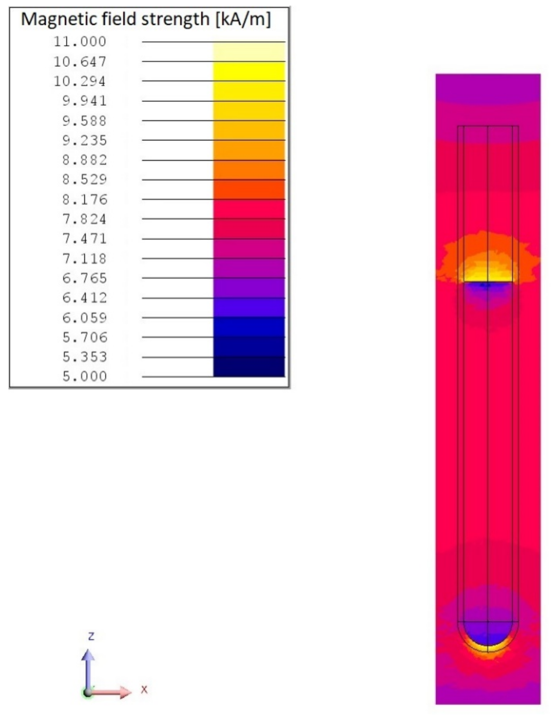
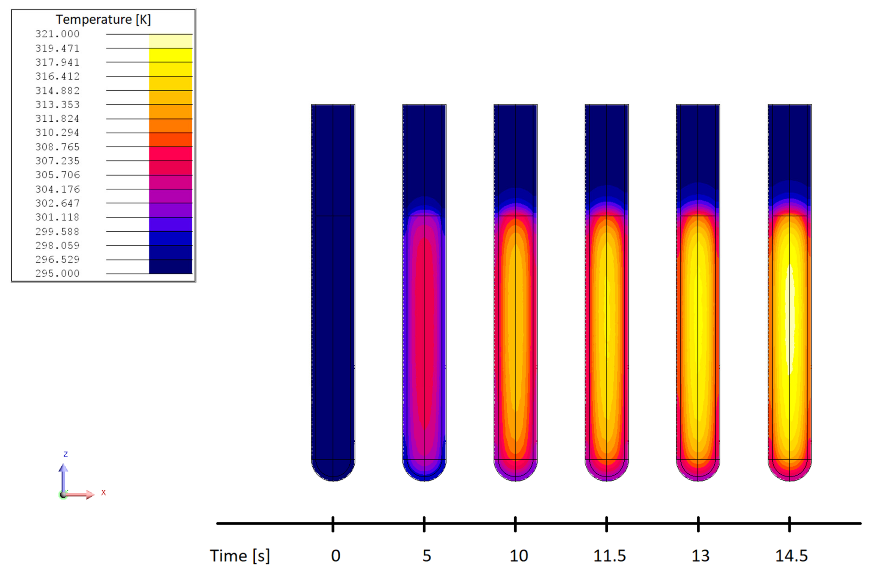
Figure 10 and Figure 11 show the magnetic field strength distribution and temperature distribution, respectively, at f = 281 kHz and H = 7.83 kA/m.

6.2. Mesh Dependency Test

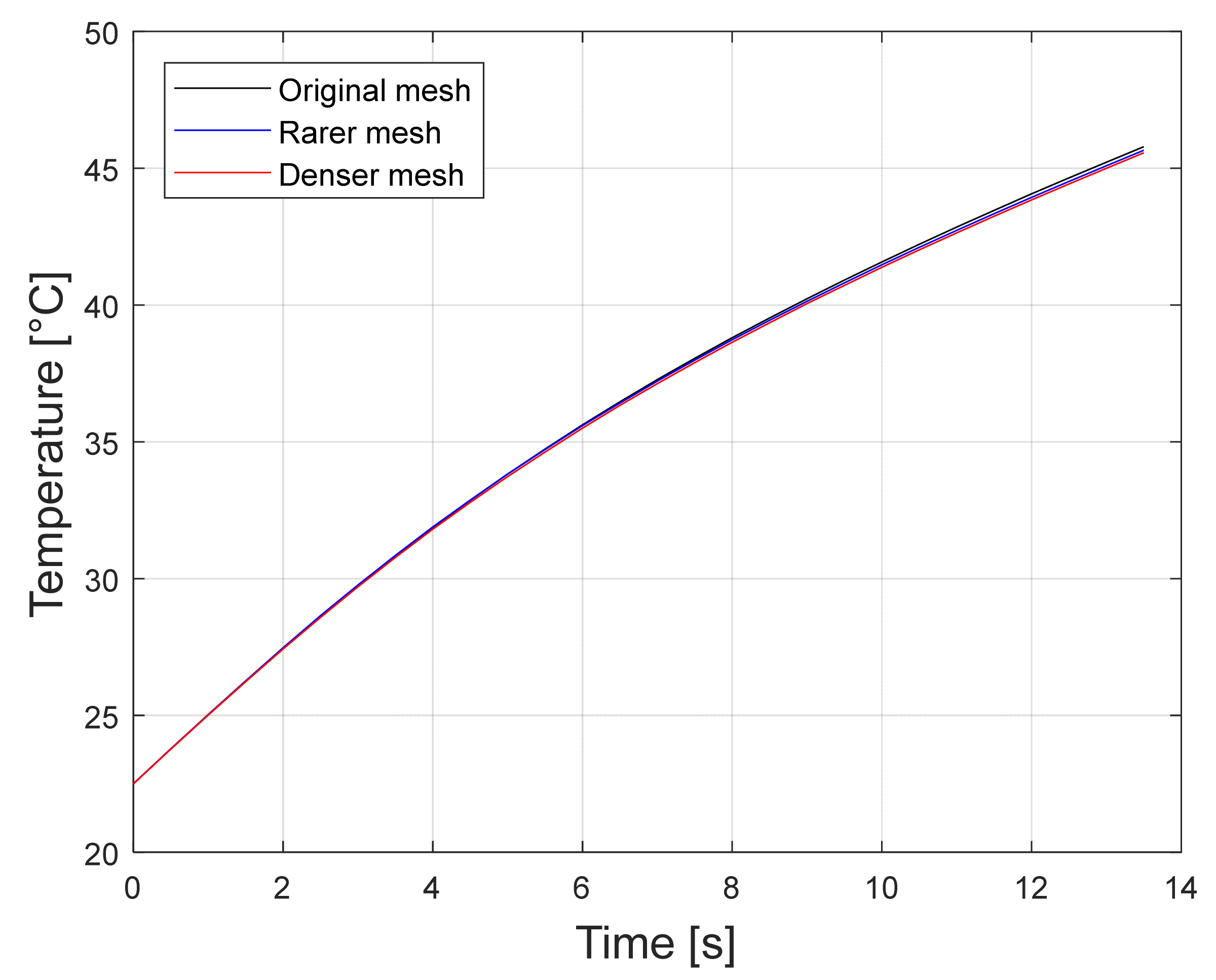
To test the mesh, a simulation was run for three different meshes at magnetic field parameters of H = 7.83 kHz and f = 281 kHz. Figure 12 shows the comparison of the results for these three meshes. The original mesh was the mesh used for all the other calculations, Rarer mesh has less elements than Original mesh, and Denser mesh has more elements.
The differences in the results with different mesh densities used were not significant (less than 0.5 %). The number of elements for used mesh densities are shown in Table 3.

6.3. Comparison with the Measurements

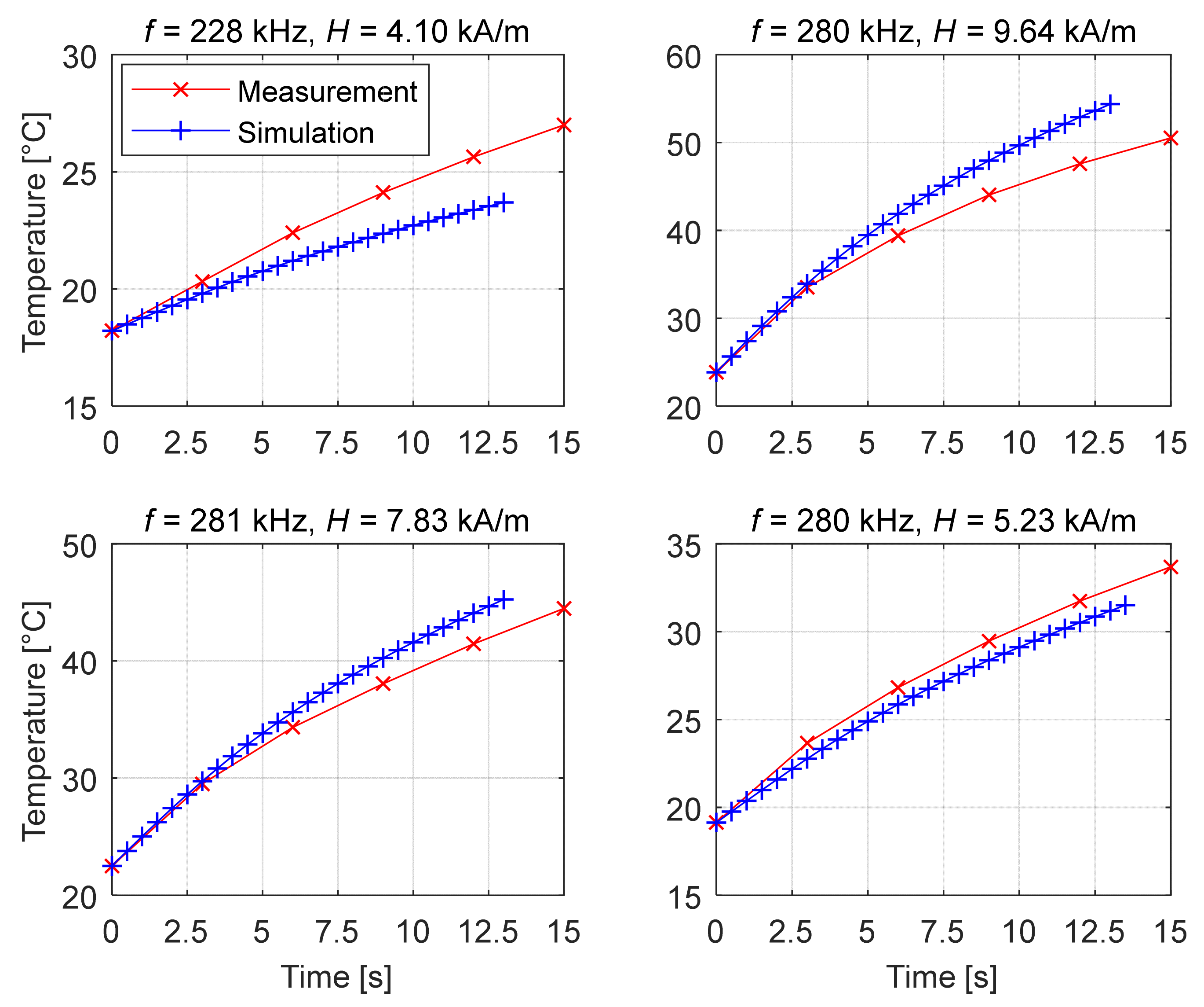
Figure 13, Figure 14 and Figure 15 represent the time evolution of temperature at different conditions (frequency, magnetic field amplitude). Since the sample volume was not the same in measurement and simulation due to the difficult exact determination of the magnetic fluid volume used for the measurement, a deviation in temperature between the two was expected. Although this was the case, the initial slope of both should be comparable and, with it, comparable SAR.
The temperature dependency on time, presented in Figure 13, Figure 14 and Figure 15, shows a similar dependency as shown in other works, like in the literature [10,16].
The SAR values obtained with Equation (1) for measurement and the initial SAR values obtained with Equation (12) for simulation were compared. The results are shown in Table 4.
The SAR values are a good indicator of the accuracy of the simulation. Relative differences in SAR values are in the range from 4.2–24.9%.

6.4. Effective Anisotropy’s Influence on the Simulation Results

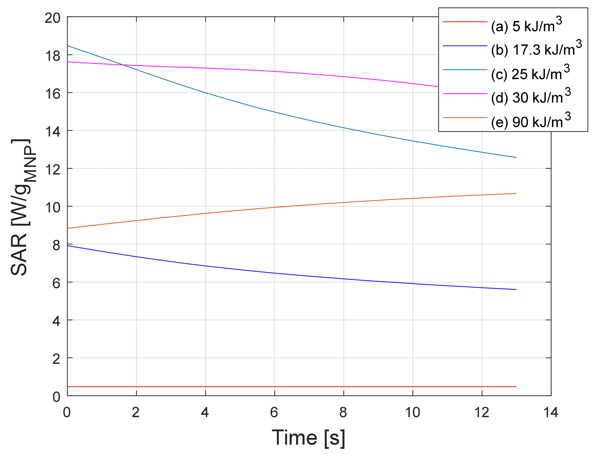
A comparison was made for the results of calculations for different values of Keff. The comparison of time–temperature curves and time–SAR curves is shown in Figure 16 and Figure 17, respectively.
In Figure 16, it can be seen that the temperature curves rise with the rising value of Keff to it being around 25 kJ/m3 and 30 kJ/m3 (curves (c) and (d) in Figure 16), for the magnetic field with parameters H = 7.83 kA/m and f = 281 kHz. At higher values of Keff, the temperature curves start falling. Looking at the time–SAR curves in Figure 17, it can be seen that time dependence changes with the changing of the Keff. For the given magnetic field, the SAR curves represented in Figure 17 are rising with Keff and falling with time for the examples (a)–(d), with examples (a)–(c) showing a similar time dependency. The time dependency changes above Keff = 25 kJ/m3. At higher values of Keff the initial SAR starts falling with Keff and rising with time (example (e)).
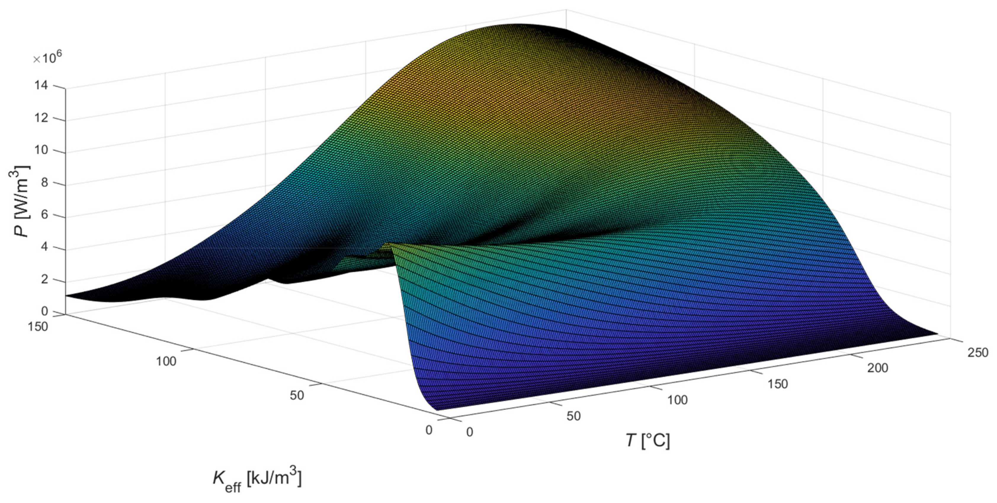
The reason for this behaviour comes down to the dependence of heating power P (SAR and P are linearly dependent) on temperature and Keff, based on Equation (11). This dependence is presented graphically in Figure 18 for the magnetic field parameters of f = 281 kHz and H = 7.83 kA/m. For lower Keff, the power output fell with the temperature increase. For higher values of Keff (around 45 kJ/m3 and up), the maximum of the power output appeared at a temperature of about 215 °C.
It can be seen that the results are heaviliy dependent on the effective anisotropy constant. In the literature [21] (Figure 5 in the literature [21]), it was shown that heating power reaches a maximum at different particle sizes for different anisotropy constants. This explains the local maximums seen in Figure 18 (heating power dependency on Keff) at low temperatures.

6.5. Magnetic Field Strength Amplitude’s Influence on the Simulation Results

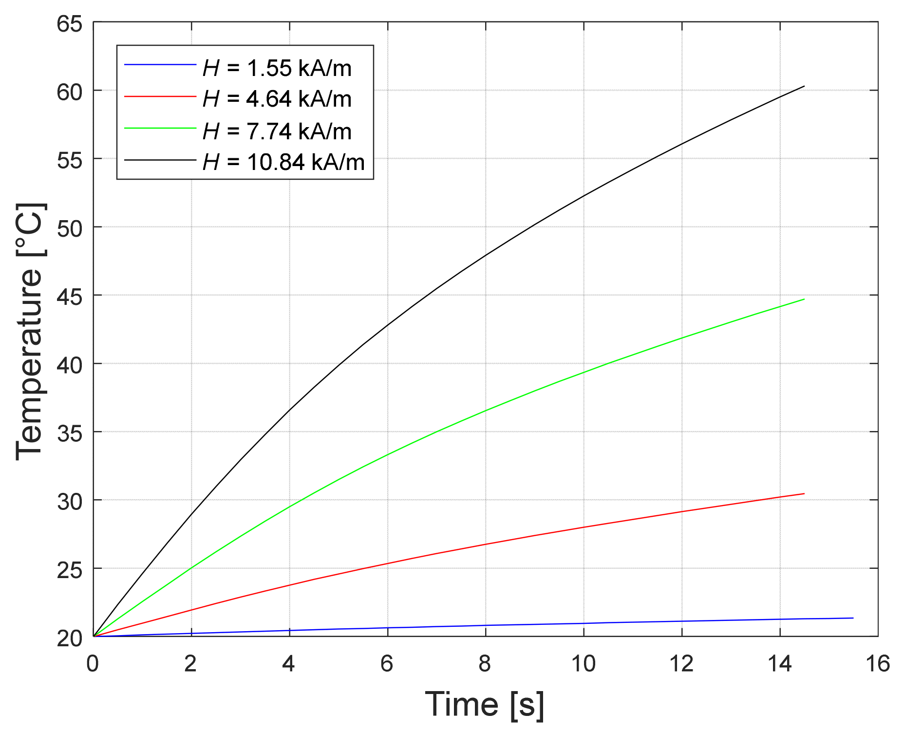
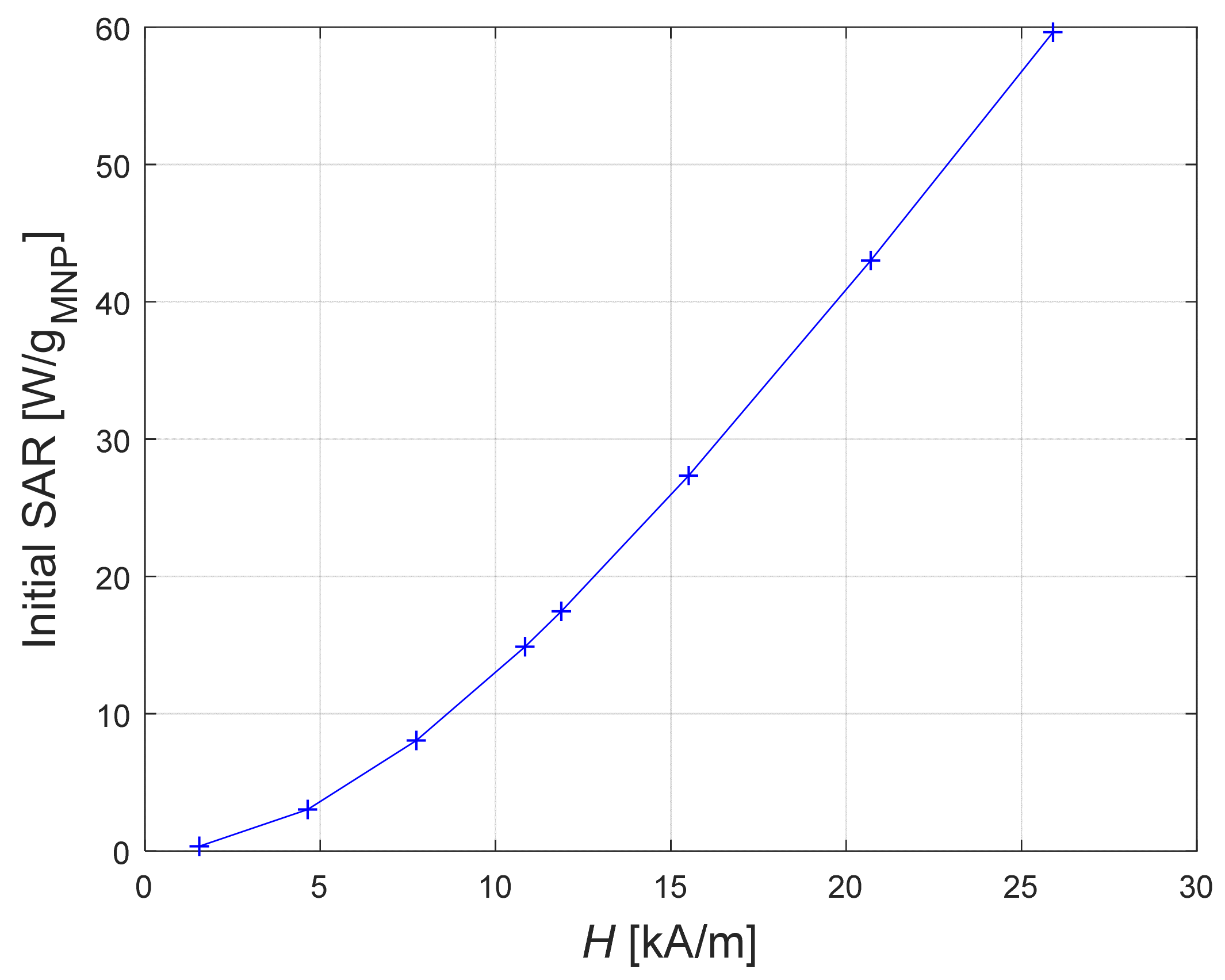
Time–temperature curves at different magnetic field strength amplitudes are represented on Figure 19.
It can be seen that, with the rising magnetic field strength amplitude, the curves rise, meaning that the heating is more intense at higher magnetic field strengths. This agrees with the findings in the literature [8,20]. Figure 20 shows the initial SAR dependence on magnetic field strength amplitude.
As seen in Figure 20, the calculated initial SAR is rising with the magnetic field strength amplitude. This agrees with the results in [8], where the results for alternating magnetic field show a similar SAR-H dependence.

6.6. Frequency’s Influence on the Simulation Results

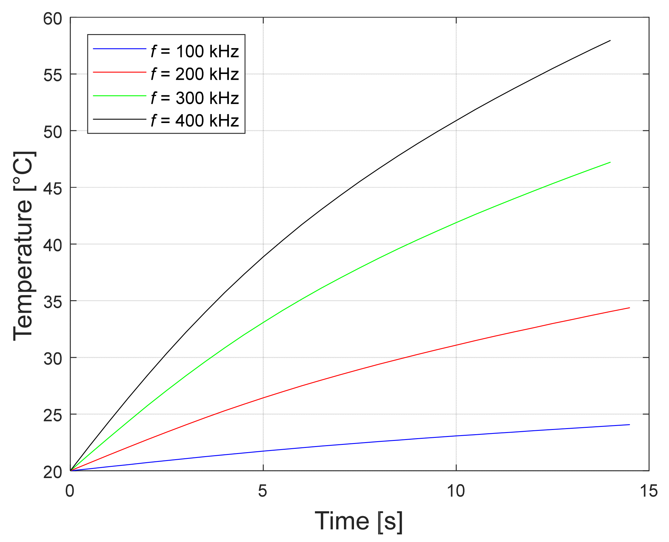
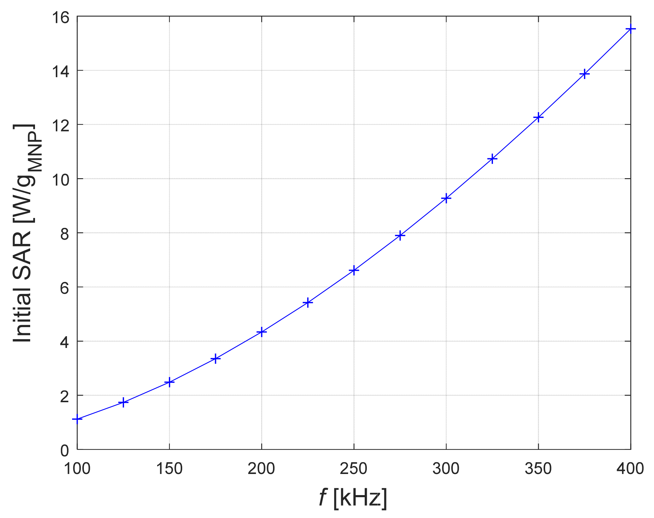
According to [8], the heating power should be increasing with the frequency. This is confirmed with Figure 21 which shows time–temperature curves calculated at different frequencies, and Figure 22 which shows how initial SAR rises with frequency.

6.7. Discussion of the Results’ Accuracy

The accuracy of the results is limited, as is seen from the simulation results deviations from the measurements (4.2–24.9%). Comparing these results with the results from studies that use measured heating power as a simulation input [9,10], the second ones are certainly more accurate. However, they are limited to one specific fluid, while our method could be expanded to magnetic fluids with different parameters. The studies simulating the heating of a tissue with embedded MNPs [11,12,13,14,15,16] give better understanding of the heating of such tissues. However, they do not give the representation of the heating of the magnetic fluid by itself.

7. Conclusions

A novel simulation model to simulate the heating of a magnetic fluid in an alternating magnetic field in a laboratory setting, considering the coupling between steady state magnetic and transient thermal calculations was built, and the quality of the model was proved with the presented tests. The main issue of the presented model was the appropriate determination of the parameters used for spatial quantities, determination of material’s properties, determination of the radiation and convection face regions, and adjustment of equations for coupling between the thermal calculations. All issues were solved. The model was validated with the measurement of a commercial magnetic fluid. The results show a 4.2–24.9% divergence between measurement and simulation in the SAR values.
An analysis of how changing Keff affects the simulation results shows that the accuracy of the calculations depends heavily on the accurate selection of the effective anisotropy constant. Therefore, it is essential how this constant is set. The calculation results show the increase in heating power with rising Keff up until a certain value, where it starts to fall again (Figure 16 and Figure 17). Additional analysis (Figure 18) shows that the heating power dependency on the Keff reaches a maximum at a certain value (around 30 kJ/m3 for the magnetic field parameters used in the analysis) at lower temperatures (0–180 °C). With higher Keff values the heating power starts falling, but it starts rising with temperature and reaches a maximum value at around 215 °C.
Magnetic field strength dependence (Figure 19) shows an increase in time–temperature curves with the increase of the magnetic field strength amplitude. The increase in heating power is more evident in Figure 20, where the initial SAR dependence on magnetic field strength amplitude is presented.
Frequency dependence (Figure 21) shows an increase in time–temperature with increasing frequency. The heating power increase with the frequency is shown in Figure 22.
Such a model can be used for assessing the heating performance of a magnetic fluid with selected parameters. It can also be used to search for the optimal parameters required to design an optimal magnetic fluid. A model like this has several advantages. It is simple, many simulations can be carried out in a relatively short amount of time, comparisons between fluids with different parameters can be made, and it gives the intrinsic heating properties of the magnetic fluid.
In future work, our research will focus on the development and use of another mathematical model for simulating the magnetic fluid heating process, or simulating another material heating using a similar approach and carrying out the corresponding measurements.

Author Contributions

Conceptualization, J.V., M.B., A.H. and M.J.; methodology, J.V.; software, J.V.; validation, J.V., M.B. and A.H.; formal analysis, A.H.; investigation, J.V.; resources, A.H.; writing—original draft preparation, J.V.; writing—review and editing, J.V., M.B., A.H. and M.J.; visualization, J.V.; supervision, M.J. and A.H. All authors have read and agreed to the published version of the manuscript.

Funding

This work was supported by the Slovenian Research Agency under Grant P2-0114.

Institutional Review Board Statement

Not applicable.

Informed Consent Statement

Not applicable.

Data Availability Statement

Not applicable.

Conflicts of Interest

The authors declare no conflict of interest.

References

  1. Lanier, O.; Korotych, O.I.; Monsalve, A.G.; Wable, D.; Savliwala, S.; Grooms, N.W.F.; Nacea, C.; Tuitt, O.R.; Dobson, J. Evaluation of magnetic nanoparticles for magnetic fluid hyperthermia. Int. J. Hyperth. 2019, 36, 687–701. [Google Scholar] [CrossRef]
  2. Smakulski, P.; Pietrowicz, S.; Ishimoto, J. The numerical modeling of cell freezing in binary solution under subcooling conditions. Int. J. Numer. Methods Heat Fluid Flow 2020, 30, 3005–3025. [Google Scholar] [CrossRef]
  3. Beković, M.; Hamler, A. Determination of the Heating Effect of Magnetic Fluid in Alternating Magnetic Field. IEEE Trans. Magn. 2010, 46, 552–555. [Google Scholar] [CrossRef]
  4. Kandasamy, G.; Sudame, A.; Bhati, P.; Chakrabarty, A.; Maity, D. Systematic investigations on heating effects of carboxyl-amine functionalized superparamagnetic iron oxide nanoparticles (SPIONs) based ferrofluids for in vitro cancer hyperthermia therapy. J. Mol. Liq. 2018, 256, 224–237. [Google Scholar] [CrossRef]
  5. Kandasamy, G.; Sudame, A.; Bhati, P.; Chakrabarty, A.; Kale, S.N.; Maity, D. Systematic magnetic fluid hyperthermia studies of carboxyl functionalized hydrophilic superparamagnetic iron oxide nanoparticles based ferrofluids. J. Colloid Interface Sci. 2018, 514, 534–543. [Google Scholar] [CrossRef]
  6. Khoramian, S.; Saeidifar, M.; Zamanian, A.; Saboury, A. Synthesis and characterization of biocompatible ferrofluid based on magnetite nanoparticles and its effect on immunoglobulin G as an immune protein. J. Mol. Liq. 2019, 273, 326–338. [Google Scholar] [CrossRef]
  7. Rosensweig, R. Heating magnetic fluid with alternating magnetic field. J. Magn. Magn. Mater. 2002, 252, 370–374. [Google Scholar] [CrossRef]
  8. Beković, M.; Trbušić, M.; Gyergyek, S.; Trlep, M.; Jesenik, M.; Szabo, P.S.B.; Hamler, A. Numerical Model for Determining the Magnetic Loss of Magnetic Fluids. Materials 2019, 12, 591. [Google Scholar] [CrossRef] [Green Version]
  9. Bekovic, M. FEM Thermal Calculation of the Warming of Magnetic Fluid Exposed to Alternating Magnetic Field. 2010. Available online: https://www.semanticscholar.org/paper/FEM-Thermal-Calculation-of-the-Warming-of-Magnetic-Bekovic/1097570d4e8b04dacbe9b66601653609970788d3 (accessed on 31 August 2021).
  10. Raouf, I.; Lee, J.; Kim, H.S.; Kim, M.-H. Parametric investigations of magnetic nanoparticles hyperthermia in ferrofluid using finite element analysis. Int. J. Therm. Sci. 2021, 159, 106604. [Google Scholar] [CrossRef]
  11. Rast, L.; Harrison, J.G. Computational Modeling of Electromagnetically Induced Heating of Magnetic Nanoparticle Materials for Hyperthermic Cancer Treatment. PIERS Online 2010, 6, 690–694. [Google Scholar] [CrossRef] [Green Version]
  12. Miaskowski, A.; Sawicki, B. Magnetic Fluid Hyperthermia Modeling Based on Phantom Measurements and Realistic Breast Model. IEEE Trans. Biomed. Eng. 2013, 60, 1806–1813. [Google Scholar] [CrossRef]
  13. Adhikary, K.; Banerjee, M. A Thermofluid Analysis of the Magnetic Nanoparticles Enhanced Heating Effects in Tissues Embedded with Large Blood Vessel during Magnetic Fluid Hyperthermia. J. Nanoparticles 2016, 2016, 6309231. [Google Scholar] [CrossRef] [Green Version]
  14. Candeo, A.; Dughiero, F. Numerical FEM Models for the Planning of Magnetic Induction Hyperthermia Treatments with Nanoparticles. IEEE Trans. Magn. 2009, 45, 1658–1661. [Google Scholar] [CrossRef]
  15. Li, J.; Yao, H.; Lei, Y.; Huang, W.; Wang, Z.; Yan, L. Numerical simulation of magnetic fluid hyperthermia based on multiphysics coupling and recommendation on preferable treatment conditions. Curr. Appl. Phys. 2019, 19, 1031–1039. [Google Scholar] [CrossRef]
  16. Xu, Y.; Wang, J.; Hou, H.; Shao, J. Simulation analysis of coupled magnetic-temperature fields in magnetic fluid hyperthermia. AIP Adv. 2019, 9, 105317. [Google Scholar] [CrossRef]
  17. Reis, R.F.; Loureiro, F.; Lobosco, M. 3D numerical simulations on GPUs of hyperthermia with nanoparticles by a nonlinear bioheat model. J. Comput. Appl. Math. 2016, 295, 35–47. [Google Scholar] [CrossRef]
  18. Salloum, M.; Ma, R.; Zhu, L. Anin-vivoexperimental study of temperature elevations in animal tissue during magnetic nanoparticle hyperthermia. Int. J. Hyperth. 2008, 24, 589–601. [Google Scholar] [CrossRef]
  19. Engelmann, U.M.; Shasha, C.; Teeman, E.; Slabu, I.; Krishnan, K.M. Predicting size-dependent heating efficiency of magnetic nanoparticles from experiment and stochastic Néel-Brown Langevin simulation. J. Magn. Magn. Mater. 2019, 471, 450–456. [Google Scholar] [CrossRef]
  20. Papadopoulos, C.; Efthimiadou, E.K.; Pissas, M.; Fuentes, D.; Boukos, N.; Psycharis, V.; Kordas, G.; Loukopoulos, V.C.; Kagadis, G.C. Magnetic fluid hyperthermia simulations in evaluation of SAR calculation methods. Phys. Med. 2020, 71, 39–52. [Google Scholar] [CrossRef]
  21. Deatsch, A.E.; Evans, B.A. Heating efficiency in magnetic nanoparticle hyperthermia. J. Magn. Magn. Mater. 2014, 354, 163–172. [Google Scholar] [CrossRef]
  22. Karvelas, E.; Lampropoulos, N.; Sarris, I. A numerical model for aggregations formation and magnetic driving of spherical particles based on OpenFOAM®. Comput. Methods Programs Biomed. 2017, 142, 21–30. [Google Scholar] [CrossRef]
  23. Vartholomeos, P.; Mavroidis, C. In Silico Studies of Magnetic Microparticle Aggregations in Fluid Environments for MRI-Guided Drug Delivery. IEEE Trans. Biomed. Eng. 2012, 59, 3028–3038. [Google Scholar] [CrossRef]
  24. Mathieu, J.-B.; Martel, S. Aggregation of magnetic microparticles in the context of targeted therapies actuated by a magnetic resonance imaging system. J. Appl. Phys. 2009, 106, 044904. [Google Scholar] [CrossRef]
  25. Beković, M.; Goričan, V.; Hamler, A. Materiali s Posebnimi Lastnostmi in Pojavi—Laboratorijske Vaje. 2019. Available online: https://www.um.si/studij/podiplomski-studij/Lists/Studijski%20progami%202stopnja/Attachments/3/U%C4%8Dni%20na%C4%8Drti.pdf (accessed on 31 August 2021).
  26. Viswanath, D.S.; Ghosh, T.K.; Prasad, D.H.L.; Dutt, N.V.K.; Rani, K.Y. (Eds.) Correlations and estimation of pure liquid viscosity. In Viscosity of Liquids: Theory, Estimation, Experiment, and Data; Springer: Dordrecht, The Netherland, 2007; pp. 135–405. ISBN 978-1-4020-5482-2. [Google Scholar]
  27. Berndt, T.; Muxworthy, A.R.; Paterson, G.A. Determining the magnetic attempt time τ 0, its temperature dependence, and the grain size distribution from magnetic viscosity measurements. J. Geophys. Res. Solid Earth 2015, 120, 7322–7336. [Google Scholar] [CrossRef] [Green Version]
  28. Cullity, B.D.; Graham, C.D. Magnetic Anisotropy. In Introduction to Magnetic Materials; John Wiley & Sons, Ltd.: Hoboken, NJ, USA, 2008; pp. 197–239. ISBN 978-0-470-38632-3. [Google Scholar]
  29. Carrey, J.; Mehdaoui, B.; Respaud, M. Simple models for dynamic hysteresis loop calculations of magnetic single-domain nanoparticles: Application to magnetic hyperthermia optimization. J. Appl. Phys. 2011, 109, 083921. [Google Scholar] [CrossRef]
  30. Komorida, Y.; Mito, M.; Deguchi, H.; Takagi, S.; Millán, A.; Silva, N.J.O.; Palacio, F. Surface and core magnetic anisotropy in maghemite nanoparticles determined by pressure experiments. Appl. Phys. Lett. 2009, 94, 202503. [Google Scholar] [CrossRef] [Green Version]
  31. Figueroa, A.; Bartolomé, J.; García, L.; Arauzo, A.; Millán, A.; Palacio, F. Magnetic Anisotropy of Maghemite Nanoparticles Probed by RF Transverse Susceptibility. Phys. Procedia 2015, 75, 1050–1057. [Google Scholar] [CrossRef] [Green Version]
  32. Pisane, K.L.; Singh, S.; Seehra, M.S. Unusual enhancement of effective magnetic anisotropy with decreasing particle size in maghemite nanoparticles. Appl. Phys. Lett. 2017, 110, 222409. [Google Scholar] [CrossRef] [Green Version]
  33. Usov, N.; Barandiarán, J.M. Magnetic nanoparticles with combined anisotropy. J. Appl. Phys. 2012, 112, 53915. [Google Scholar] [CrossRef]
  34. Engineering ToolBox. Air—Density, Specific Weight and Thermal Expansion Coefficient at Varying Temperature and Constant Pressures. Available online: https://www.engineeringtoolbox.com/air-density-specific-weight-d_600.html (accessed on 13 April 2021).
  35. Engineering ToolBox. Air—Specific Heat at Constant Pressure and Varying Temperature. Available online: https://www.engineeringtoolbox.com/air-specific-heat-capacity-d_705.html (accessed on 13 April 2021).
  36. Engineering ToolBox. Air—Thermal Conductivity. Available online: https://www.engineeringtoolbox.com/air-properties-viscosity-conductivity-heat-capacity-d_1509.html (accessed on 13 April 2021).
  37. Saint-Gobain Sekurit Glass Properties. Available online: https://www.saint-gobain-sekurit.com/global-excellence/our-production-processes/glossary (accessed on 3 May 2021).
  38. Genc, S. Heat Transfer of Ferrofluids. In Nanofluid Heat and Mass Transfer in Engineering Problems; Kandelousi, M.S., Ed.; InTechOpen: Rijeka, Croatia, 2017. [Google Scholar]
  39. Nadolny, Z.; Dombek, G.; Przybylek, P. Thermal Properties of a Mixture of Mineral Oil and Synthetic Ester in Terms of Its Application in the Transformer. In Proceedings of the 2016 IEEE Conference on Electrical Insulation and Dielectric Phenomena (CEIDP), Toronto, ON, Canada, 16–19 October 2016; pp. 857–860. [Google Scholar]
  40. Spencer, M.P.; Lee, W.; Alsaati, A.; Breznak, C.M.; Branco, R.B.N.; Dai, J.; Gomez, E.D.; Marconnet, A.; von Lockette, P.; Yamamoto, N. Cold sintering to form bulk maghemite for characterization beyond magnetic properties. Int. J. Ceram. Eng. Sci. 2019, 1, 119–124. [Google Scholar] [CrossRef] [Green Version]
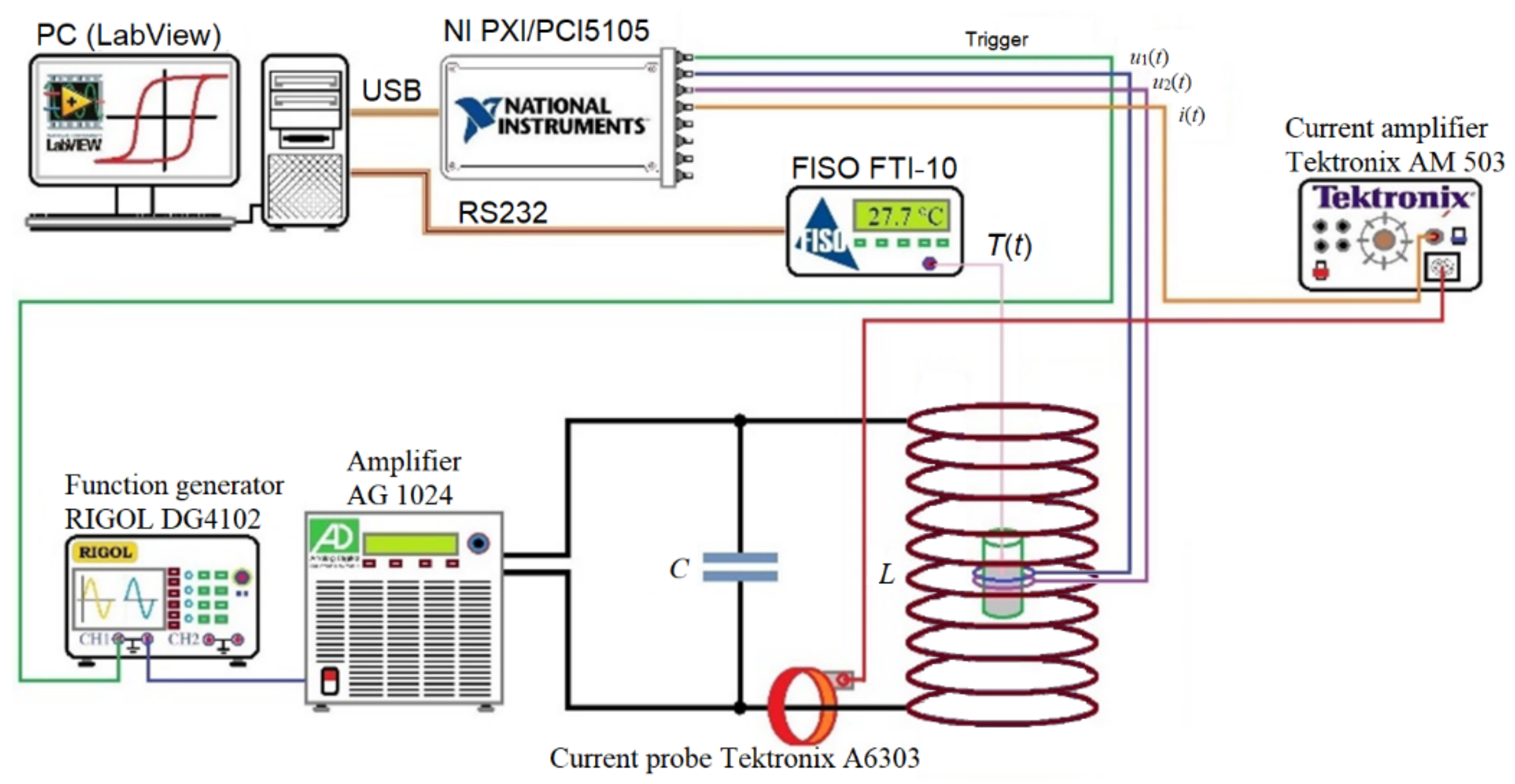
Figure 1. Schematic representation of the measurement system [25].
Mathematics 09 02561 g001
Figure 2. Schematic representation of the model’s cross-section.
Mathematics 09 02561 g002
Figure 3. Regions in the model. Regions are marked with yellow and are as follows: (a) Infinite box region, (b) Non-active air region, (c) Glass container region, (d) Air region inside the container, (e) Magnetic fluid region, and (f) Face region around the container with defined radiation emissivity, absorption, and convection coefficients.
Mathematics 09 02561 g003
Figure 4. Simulation flowchart.
Mathematics 09 02561 g004
Figure 5. Location of the temperature and Specific Absorption Rate (SAR) readings and Infinite box boundary conditions.
Mathematics 09 02561 g005
Figure 6. Size distribution of MNPs.
Mathematics 09 02561 g006
Figure 7. Temperature dependence of the specific heat capacity of air, using the data obtained from [35].
Mathematics 09 02561 g007
Figure 8. Temperature dependence of the thermal conductivity of air, using the data obtained from literature [36].
Mathematics 09 02561 g008
Figure 9. Temperature dependence of the initial relative permeability of the magnetic fluid.
Mathematics 09 02561 g009
Figure 10. Cross-section of the magnetic field distribution inside the container, at f = 281 kHz and H = 7.83 kA/m.
Mathematics 09 02561 g010
Figure 11. Cross-section view of the time dependence of temperature distribution inside the container, at f = 281 kHz and H = 7.83 kA/m.
Mathematics 09 02561 g011
Figure 12. Comparison of the results between different mesh densities at field parameters of H = 7.83 kA/m and f = 281 kHz.
Mathematics 09 02561 g012
Figure 13. Comparison of time–temperature of measurement and simulation at the selected point.
Mathematics 09 02561 g013
Figure 14. Comparison of time–temperature of measurement and simulation at the selected point.
Mathematics 09 02561 g014
Figure 15. Comparison of time–temperature of measurement and simulation at the selected point.
Mathematics 09 02561 g015
Figure 16. Comparison of time–temperature curves at different Keff. at magnetic field parameters being f = 281 kHz and H = 7.83 kA/m.
Mathematics 09 02561 g016
Figure 17. Comparison of time–SAR curves at different Keff. at magnetic field parameters being f = 281 kHz and H = 7.83 kA/m.
Mathematics 09 02561 g017
Figure 18. Heating power P dependence on temperature T, and anisotropy constant Keff of the magnetic fluid at field parameters f = 281 kHz and H = 7.83 kA/m.
Mathematics 09 02561 g018
Figure 19. Calculated time–temperature curves at different magnetic field strength amplitudes with frequency being f = 281 kHz.
Mathematics 09 02561 g019
Figure 20. Initial SAR dependence on magnetic field strength amplitude at frequency being f = 281 kHz.
Mathematics 09 02561 g020
Figure 21. Calculated time–temperature curves at different frequencies with magnetic field strength amplitude being H = 7.83 kA/m.
Mathematics 09 02561 g021
Figure 22. Initial SAR dependence on frequency at the magnetic field strength amplitude being H = 7.83 kA/m.
Mathematics 09 02561 g022
Table 1. Groups of different sized magnetic nanoparticles (MNPs) with corresponding volume fractions.
MNP Size [nm]Volume Fraction ϕ [%]
4.50.1004
5.50.4887
6.51.0080
7.51.6110
8.52.2100
9.51.4480
10.51.4450
11.50.8935
12.51.0040
13.50.3613
Table 2. Values of parameters (for spatial quantities) used in the simulation.
ParameterValue
Attempt time τ010−9 s
Effective anisotropy Keff17.3 kJ/m3
Saturation magnetization of the bulk material Ms400 kA/m
Table 3. Number of nodes, line elements, surface elements and volume elements for the three meshes used in the comparison.
Type of ElementNumber of Elements (Original Mesh)Number of Elements (Rarer Mesh)Number of Elements (Denser Mesh)
Node29,83916,71834,921
Line element212610652646
Surface element30,40815,79436,674
Volume element168,53795,482195,612
Table 4. Comparison of measured and calculated SAR values at given magnetic field frequency and amplitude.
Field Frequency f [kHz]Field Strength Amplitude H [kA/m]Measured SAR [W/gFe]Calculated SAR [W/gFe]Deviation from Measurement [%]
10113.503.3303.0628.05
10011.682.6922.29514.75
1009.752.2401.68324.87
2297.804.2964.90814.25
2284.102.1581.65923.12
2809.649.92711.28813.71
2817.837.1947.92010.09
2805.234.6453.84917.14
2793.051.7881.34624.72
2791.550.3700.3505.41
3976.4810.64610.1974.22
Publisher’s Note: MDPI stays neutral with regard to jurisdictional claims in published maps and institutional affiliations.