Article

Steric Effects on Electroosmotic Nano-Thrusters under High Zeta Potentials

School of Mathematical Science, Inner Mongolia University, Hohhot 010021, China
*
Author to whom correspondence should be addressed.
Mathematics 2021, 9(24), 3222; https://doi.org/10.3390/math9243222
Submission received: 9 November 2021 / Revised: 8 December 2021 / Accepted: 11 December 2021 / Published: 13 December 2021

Abstract

:
Here, space electroosmotic thrusters in a rigid nanochannel with high wall zeta potentials are investigated numerically, for the first time, considering the effect of finite size of the ionic species. The effect, which is called a steric effect, is often neglected in research about micro/nano thrusters. However, it has vital influences on the electric potential and flow velocity in electric double layers, so that the thruster performances generated by the fluid motion are further affected. These performances, including thrust, specific impulse, thruster efficiency, and the thrust-to-power ratio, are described by using numerical algorithms, after obtaining the electric potential and velocity distributions under high wall zeta potentials ranging from −25.7 mV to −128.5 mV. As expected, the zeta potential can promote the development of thruster performances so as to satisfy the requirement of space missions. Moreover, for real situation with consideration of the steric effect, the thruster thrust and efficiency significantly decrease to 5–30 micro Newtons and 80–90%, respectively, but the thrust-to-power ratio is opposite, and expends a short specific impulse of about 50–110 s.

1. Introduction

In the programing of many space missions, building a platform that can deliver generated performances of a spacecraft and minimize its weight, as well as power consumption, is critical so as to satisfy the requirements of small mass, high efficiency, and low cost thrusters [1,2]. Hence, micro/nano thrusters or small spacecraft have become a major focus in aerospace engineering, owing to their capability to perform high-resolution measurements and complex and multi-purpose tasks, while also enhancing mission efficiency and reducing launch costs [3,4,5,6,7]. Compared with the conventional propulsion methodologies, electric propulsion (EP) technology [8,9,10] based on the electrokinetic electroosmosis principle has presented better advantages for controlling fluids and promoting device performance. The characteristics of electroosmosis have been extensively studied and employed in micro/nano fluid designs [11,12,13,14,15,16,17,18]. Rice and Whitehead [19] analyzed the electroosmosis flow (EOF) in a capillary tube under the Debye–Huckel approximation with consideration of small zeta potentials on the walls, and further predicted the maximum for the electroviscous effect. Mala et al. [20] investigated the influences of electric double layer (EDL) on EOF between two parallel plates, experimentally and theoretically. Moreover, transient EOF of Maxwell fluids was developed by Escandón et al. [21] in a microchannel with asymmetric zeta potentials by solving the Cauchy momentum equation and the Poisson equation.
Based on the above mentioned research work, many results and methods have been obtained regarding the basic theory of electrokinetic electroosmotic transport, so that they are able to be introduced appropriately to the space propulsion system [22]. For instance, Huang and Huang [23] recently studied two-liquid electroosmotic thrusters with nanochannels and achieved a short specific impulse and high thruster efficiency, of about 246.9 s and 82%, respectively. The performances of electroosmotic thrusters in soft nanochannels were further considered by Zheng and Jian [24,25], who obtained up to 90% efficiency, as well as a few micro Newtons of thrust. These works pertaining to electroosmotic thrusters were carried out under the condition of a small electric potential, so, in the present paper, we firstly tried to investigate thruster performances in a rigid nanochannel considering the effects of a high zeta potential on the walls. Under such a zeta potential case, many studies regarding EOF have been conducted by experts and scholars [26,27,28]. Kang et al. [29] achieved analytical solutions of the electric potential and the electroosmosis velocity through an annulus with two cylindrical walls carrying high zeta potentials and found a linear increasing relationship between the zeta potential and flow velocity. Nekoubin [30] numerically presented the distribution of electroosmotic flow of non-Newtonian fluids in a curved rectangular microchannel with a high zeta potential and found that the increase in zeta potential could significantly increase the volumetric flow rate. Furthermore, the combined electroosmotic and pressure-driven flow in a microchannel was designed by Mondal et al. [31] with a wall zeta potential from 77 mV to 120 mV, which had a great effect on EOF when the pressure was very low.
It is noted, however, that the ions in these studies were regarded as point charges and their volumes were neglected. In fact, the finite size ion has significant influences on EDL and EOF, which is further added to the present paper about electroosmotic nano-thrusters with high wall zeta potentials. The ionic size effect and steric effect are determined by the steric factor ν, which is the mean volume of each ion, taken as ν = a3n0 [32]. Here, a is the effective ionic size and n0 is the ionic concentration of the bulk solution under neutral conditions. When the steric factor is equal to zero, these ions are thought of as point charges without consideration of their steric effect. The influences of the steric effect on the mixed electroosmotic and pressure driven flows are presented by Dey et al. [33], considering the thermal transport process. They obtained the result that the flow velocity decreased with the steric factor when the electrokinetic width was small. The influence of the steric effect was first added by Zheng et al. [34] in space electroosmotic thrusters with soft nanochannels. They found that the thruster efficiency was only 30–70% and the peak values of the thrust-to-power ratio faded away, but they did not consider the high wall zeta potential. Under a high zeta potential, Jimenez et al. [35,36] numerically investigated the EOF with consideration of the combined viscoelectric and steric effects in micro/nano channels, and observed that the electroosmotic speed increased with the wall zeta potential. Yeh et al. [37] further explored the ion size effect on the electrokinetic energy conversion (EKEC) in nanofluidic devices using a modified Poisson–Boltzmann equation. Moreover, various geometries and fluids were prescribed to accurately address the influence of the finite ionic size on the electrokinetic features [38,39,40,41,42,43].
In fact, some related works about micro/nano electrokinetic thrusters have been performed by us, such as [24,25,34], but the influence of a high zeta potential on the wall was not considered. Hence, in this article, we numerically investigated the ion-size (steric) effect on the performances of elelctroosmotic thrusters in a rigid nanochannel with high wall zeta potentials ranging from −25.7 mV to −128.5 mV for the first time. Our main purpose was not only to be close to the reality that there were ions of finite size in the electrolyte solution, but also to promote the development of thruster performances via enhancing the wall zeta potential. Numerical solutions of the electric potential and velocity field were obtained by solving the modified Poisson–Boltzmann equation and Navier–Stokes equation in the finite different method. So, the thruster thrust, specific impulse, efficiency, and the thrust-to-power ratio were calculated using the composite trapezoid rule. Their variations with regard to the zeta potential and the steric factor are discussed in detail.

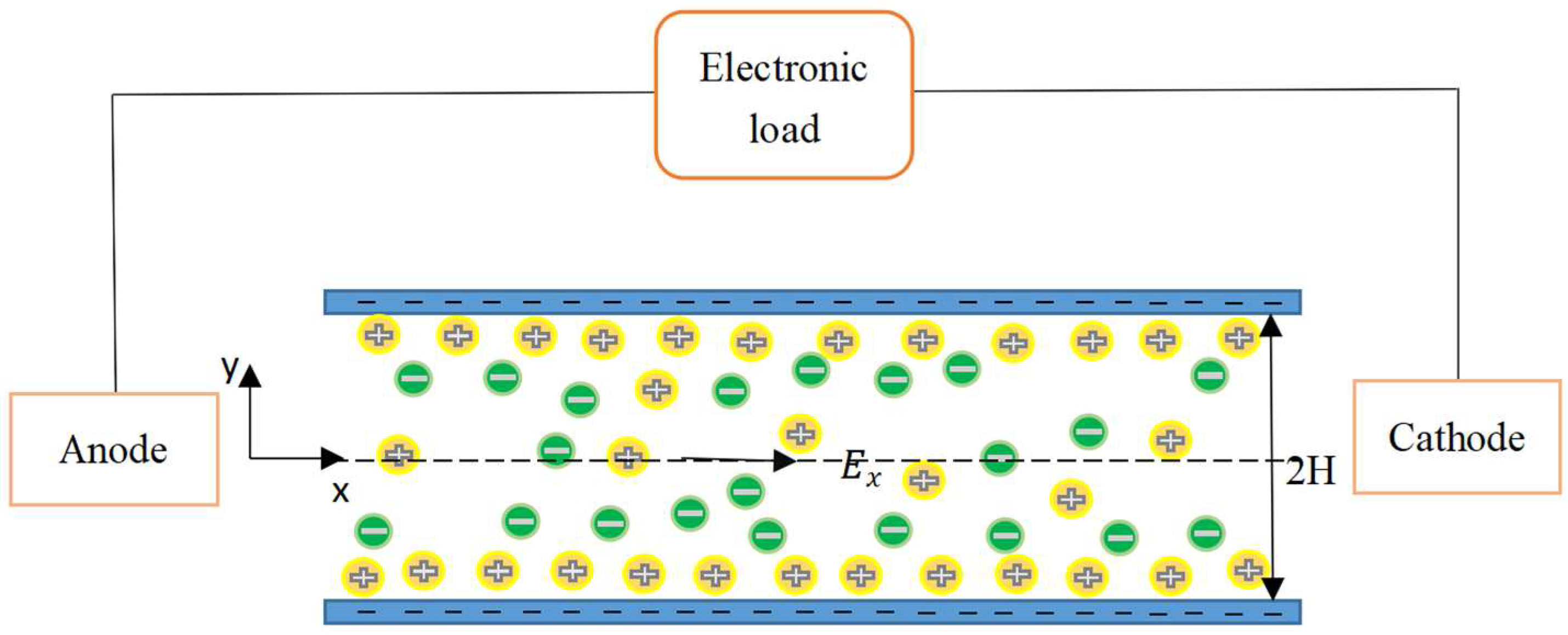
2. Mathematical Model Analysis

We considered the thruster model problem of electroosmotic-driven flows through a nanochannel with a high wall zeta potentials under the steric effect. The nanochannel in electroosmotic thrusters is showed in Figure 1, whose length, width, and height were set as L, W, and 2H, respectively. It was assumed that the nanochannel length and depth were both much larger than the height, i.e., L >> H, W >> H, so that the flow field was between two infinite parallel plates and was simplified as unidirectional and inertia-free [20,23,24,25,27,28,36,44]. For convenience, the Cartesian coordinates were chosen, and its origin was on the center of the channel. In addition, it was supposed that the liquid in the channel was an ideal solution of completely dissociated salt with respect to the x-axis symmetry, and the variation in temperature at the cross section of the channel was ignored. Our analysis was based on the simplest situation where the zeta potentials were the same as on the bottom and upper walls of this channel. The fluid motion was created by an applied electroosmotic body force of an external electric field of magnitude Ex along the direction of the main flows. We considred that the fluid squirts from the outlet of channel, meanwhile it acted as a propellant of the thruster to produce the required thrust or energy [23,24,25].

2.1. Electric Potential Distribution

Based on the symmetry condition, mathematical modeling equations were formulated in the upper half region of the nanochannel, 0 ≤ yH. For the purpose of studying the electroosmotic thruster performances generated by the fluid motion, we firstly considered that the Poisson–Boltzmann equation for electrical potential is expressed as follows [41]:
d 2 ψ d y 2 = e z ( n + n ) ε r ε 0 ,   0 < y < H ,
where ψ(y) is the electrical potential of the fluid, z is the valence number of ions, e is the elementary electric charge, εr is the relative permittivity, ε0 is the permittivity of a vacuum, and n± are number densities of the electrolyte cations and anions, respectively. Taking the steric effect into account, the ion distribution is given by the following the modified Boltzmann equation, as follows [35]:
n ± = n 0 1 + 4 v sinh 2 ( z e ψ k B T a v ) exp ( z e ψ k B T a v ) ,
where ν is the steric factor, n0 is the nominal ionic concentration in the bulk electrolyte reservoir, Tav is the average temperature, and kB is the Boltzmann constant. Substituting Equation (2) into Equation (1) leads to the following:
d 2 ψ d y 2 = 1 λ 2 sinh ( z e ψ k B T a v ) 1 + 4 v sinh 2 ( z e ψ k B T a v ) ,   0 < y < H ,
The above relationship for the electric potential within the EDL is subject to the following boundary conditions [44]:
d ψ d y | y = 0 = 0 ,
ψ | y = H = ζ .
in which ζ represents the high zeta potentials on the walls (|ζ| ≥ 25 mV), so that the electric potential in EDL is too high to use the Debye–Hückel linearization approximation. Equation (4) represents the symmetry of the electrolyte solution in the nanochannels. Furthermore, the present mathematical model is normalized by introducing the following dimensionless variables:
y * = y H ,   ψ * = e z ψ k B T a v ,   λ * = λ H ,   ζ * = e z ζ k B T a v ,
where λ = ε k B T a v / 2 n 0 e 2 z 2 is the EDL thickness. Equations (3)–(5) in non-dimension forms can be rewritten as follows:
d 2 ψ * d y * 2 = 1 λ * 2 sinh ( ψ * ) 1 + 4 v sinh 2 ( ψ * ) ,   0 < y * < 1 ,
which is subject to the following dimensionless boundary conditions:
d ψ * d y * | y = 0 = 0 ,
ψ * | y = 1 = ζ * .

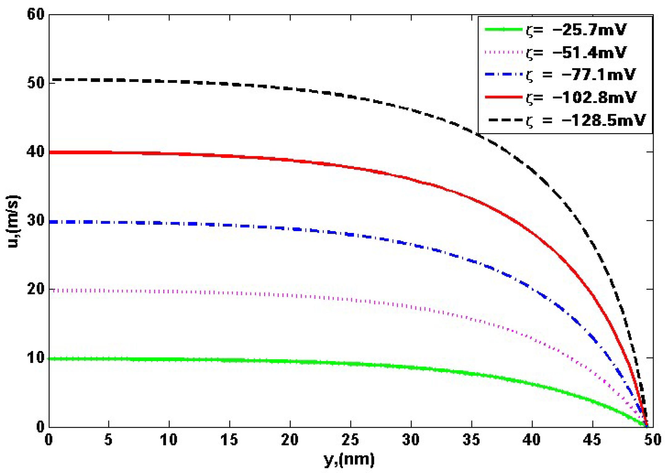
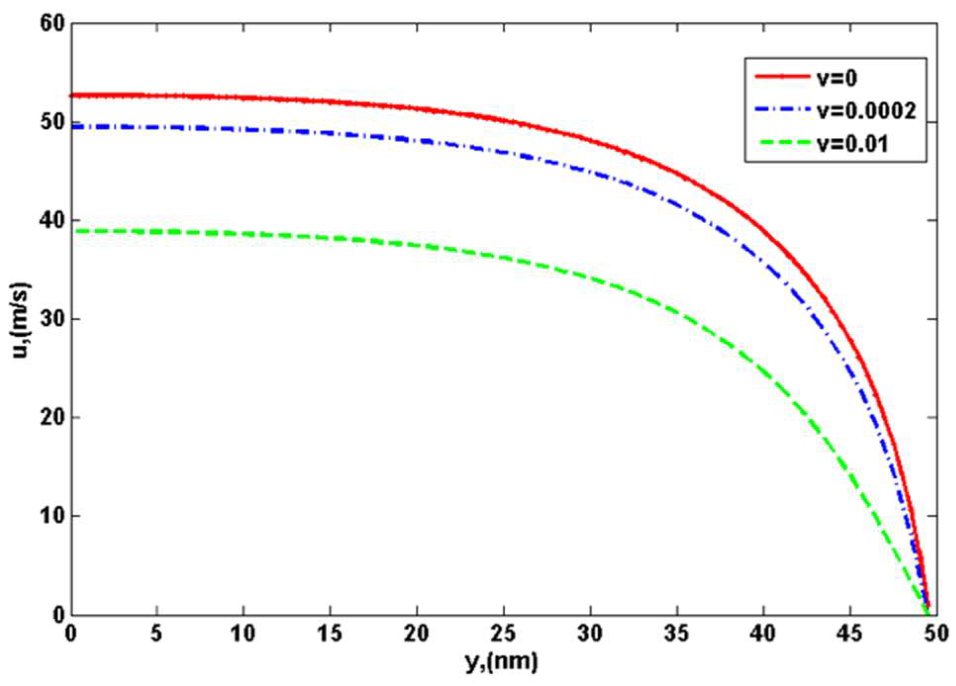
2.2. Velocity Distribution

To determine the velocity field of the electroosmotic flow, we assumed a steady, laminar, and fully developed flow, and the pressure gradient or the subsequent pressure driven flow effect was negligible in the electroosmotic thruster. First of all, theoretically, it is not difficult to consider the unsteady flow, which needs to have a time derivative term added on the left side of Equation (10). The revised equation can be numerically simulated by the finite difference method. However, the computations of the thruster performances are based on a steady velocity. Thus, we only considered steady and fully developed flow. Additionally, micro or nanoscale flows generally have a small Reynolds number flow, so the flow is laminar and is described by the Navier–Stokes equation. Therefore, the modified Navier–Stokes equation is given by [41]
μ d 2 u d y 2 = e z ( n + n ) E x ,   0 < y < H ,
it can be seen that the following boundary conditions are satisfied:
d u d y | y = 0 = 0 ,
u | y = H = γ d u d y | y = H .
Here, Ex, a uniform axial electric field, is applied between two ends of the nanochannel; μ represents dynamic viscosity of the solution; and γ implies coefficient of the slip boundary on the wall. Next, we introduced the following dimensionless variables to consider this problem simply.
u * = u u H S ,   γ * = γ H ,   u H S = ε r ε 0 k B T a v E x e z μ .
Using dimensionless variables, Equations (7) and (8) are transformed into the following non-dimension forms:
d 2 u * d y * 2 = sinh ( ψ * ) λ * 2 [ 1 + 4 v sinh 2 ( ψ * ) ] , 0 < y * < 1 ,
d u * d y * | y = 0 = 0 ,
u * | y * = 1 = γ * d u * d y * | y * = 1 .

3. Thruster Performance Analysis

To understand the features of nano electroosmotic thrusters, the standardized key performances are defined, namely the specific impulse (Isp), thrust (Th), thruster efficiency (ηt), and thrust-to-power ratio (ξ). Numerical solutions for the above electric potential and flow velocity are obtained by finite difference methods so that these performances are derived via using numerical calculation.

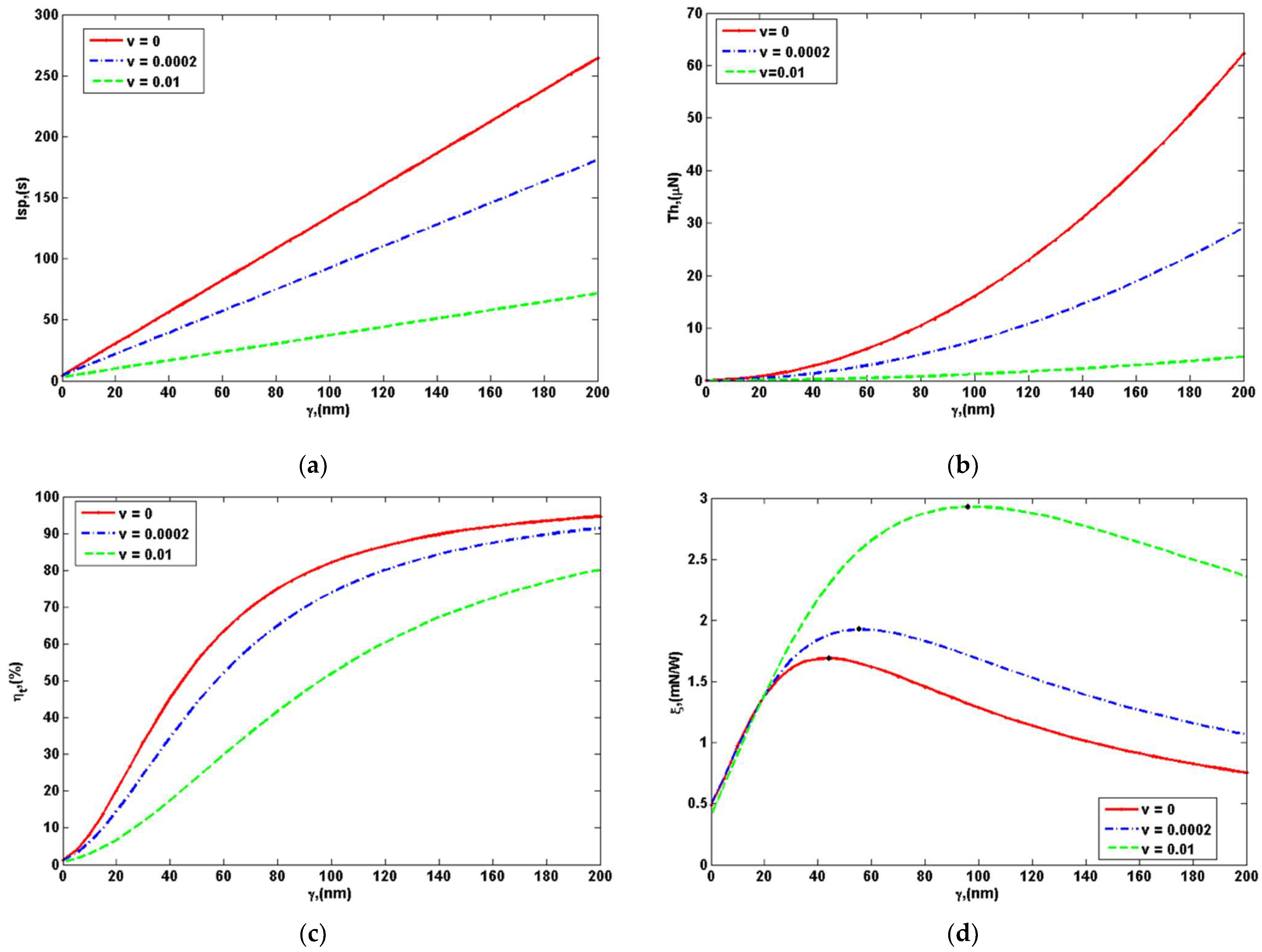
3.1. Specific Impulse

The specific impulse of the thrusters is defined as the impulse produced per unit mass of propellant in the engine, and the impulse is a process quantity that refers to the product of a force and its time of action. So, the specific impulse of thrusters is expressed as the propellant exhaust velocity divided by the gravitational acceleration constant [45,46]. It describes the utilization efficiency of a propellant and its unit is in seconds. The higher the specific impulse, the more efficient it is, the more momentum it can generate with the same mass of propellant. The specific impulse directly affects the effective load of the thrusters. Hence, it is an important performance to measure the characteristics of the thrusters. It is assumed that the propellant exhaust velocity is the average flow velocity, and the specific impulse is written as follows [23,24,25]:
I s p = 1 g 0 H 0 H u ( y ) d y ,
which can be rewritten in the non-dimensional form as
I s p * = 0 1 u * ( y * ) d y * ,
where Isp* = Ispg0/uHS with the gravitational constant g0 = 9.806 m/s2.

3.2. Thrust

Thrust, Th, is defined as the mean flow velocity multiplied by the mass flow rate of the fluid [45,46], namely, Th = mvm, where m = ρvmHW. Thus, the thrust is written as follows:
T h = 2 W 0 H ρ u 2 ( y ) d y ,
where ρ represents the density of the electrolyte, and the non-dimensional thrust is given as follows
T h * = 0 1 u * 2 ( y * ) d y *
with Th = Th*/(2WHρuHS2).

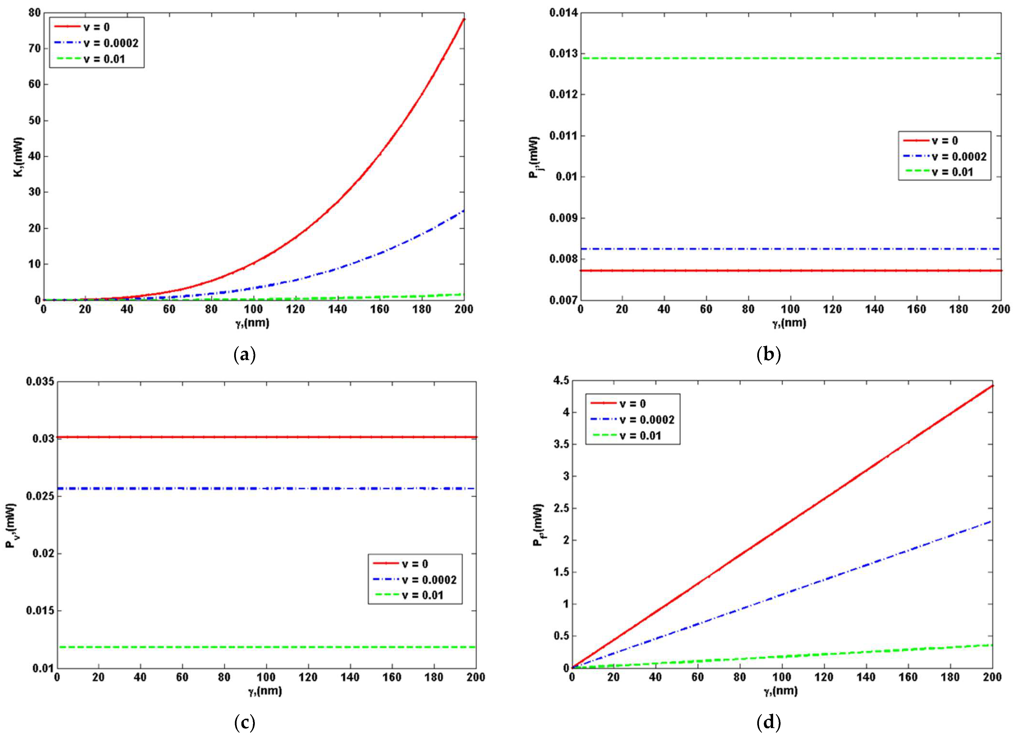
3.3. Thruster Efficiency

The total power input Pin provided by the electroosmotic thruster in the nanochannel is evaluated by investigating the total energy requirement. Under no pressure gradient or pumping pressure situations, Pin is transformed into kinetic energy of the electrolyte propellant, K; Joule heating effect, Pj; viscous dissipation, Pv; and frictional heating, Pf. Substituting the electric potential and the flow velocity into following expressions, the total power input is expressed as follows:
P i n = K + P j + P v + P f ,
with
K = A o u t 1 2 ρ u 3 d A o u t ,
P j = V σ E x 2 d V = V E x 2 σ 0 cosh ( e z ψ k B T a v ) d V ,
P v = V μ ( d u d y ) 2 d V ,
where Aout denotes the cross-sectional area of the channel, V denotes the total channel volume, and Awall represents the surface area of the wall. σ is the electrical conductivity of fluid and is subject to the following:
σ = σ 0 cosh ( e z ψ k B T a v ) ,
where σ0 is the electrical conductivity of the neutral liquid. We introduce the following dimensionless forms:
( P i n * , K * , P j * , P v * , P f * ) = ( P i n , K , P j , P v , P f ) / ( 2 W H ρ u H S 3 ) .
Non-dimensional forms of Equations (21)–(25) can be expressed as follows:
P i n * = K * + P j * + P v * + P f * ,
K * = 0 1 1 2 u * 3 d y * ,
P j * = β 0 1 cosh ( ψ * ) d y * ,
P v * = δ 0 1 ( d u * d y * ) 2 d y * ,
P f * = δ [ u * | y = 1 d u * d y * | y = 1 ] ,
where β and δ are the characteristic parameters for Joule heating and viscous frictional heating, respectively, defined as follows:
β = E x 2 σ 0 L ρ u H S 3 ,   δ = L μ H 2 ρ u H S .
So, the thruster efficiency ηt is obtained by dividing the kinetic energy by the total input power:
η t = K * P i n * = K P i n .

3.4. Thrust-to-Power Ratio

Finally, the thrust-to-power ratio, which is another significant parameter of the space thrusters, can be acquired:
ξ = T h P i n ,
the non-dimension form of the above equation is
ξ * = u H S ξ = T h * P i n * = T h * K * + P j * + P v * + P f * ,
it is worth noting that the thrust-to-power ratio is connected with the thruster efficiency and flow velocity [45,46,47], i.e.,
ξ = T h P i n ~ ρ H W v m 2 E K / η t = η t ρ H W v m 2 ρ H W v m 3 / 2 = 2 η t v m .
in which vm is the averaged velocity. This ratio strongly impacts major space mission’s characteristics such as the duration of thrust, system cost, and payload capability.

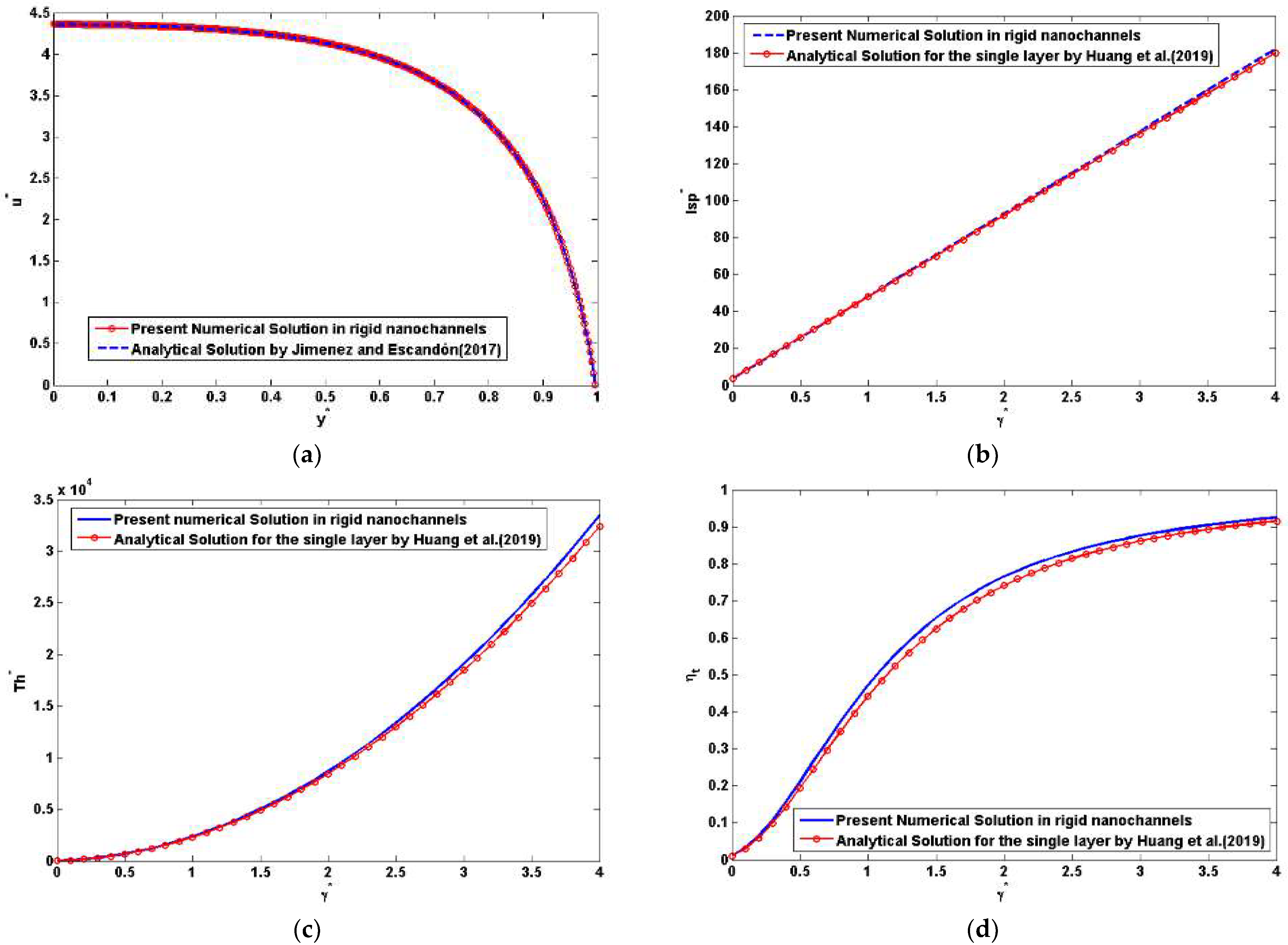
4. Numerical Algorithm

In this paper, differential Equations (7) and (14) are solved using the finite different. Because of the symmetry condition, we consider domain y to be within the interval [0, 1]. Taking the electric potential for example, Equation (7) can be discretized as follows:
ψ i + 1 2 ψ i + ψ i 1 h 2 = 1 λ 0 2 sinh ( ψ i ) 1 + 4 v sinh 2 ( ψ i ) ,   i = 2 , , n 1 ,
where the electric potential ψ at point yi is denoted as ψi = ψi(yi) (1 ≤ in), and yi is regarded as the discrete grid points and the step size is h = 1/n. Combined with the boundary conditions, we know that
2 ψ 2 2 ψ 1 h 2 = 1 λ 0 2 sinh ( ψ 1 ) 1 + 4 v sinh 2 ( ψ 1 ) ,   i = 1 ,
ψ n ζ = 0 , i = n .
We solved these discretized nonlinear differential equation groups by using the multivariate Newton’s iteration method. The function F(ψ) is written as
F ( ψ ) = [ f 1 ( ψ 1 , ψ 2 , , ψ n ) f 2 ( ψ 1 , ψ 2 , , ψ n ) f N ( ψ 1 , ψ 2 , , ψ n ) f n 1 ( ψ 1 , ψ 2 , , ψ n ) f n ( ψ 1 , ψ 2 , , ψ n ) ] = [ 2 ψ 2 2 ψ 1 h 2 sinh ( ψ 1 ) λ 2 ( 1 + 4 v sinh 2 ( ψ 1 ) ) ψ 3 2 ψ 2 + ψ 1 h 2 sinh ( ψ 2 ) λ 2 ( 1 + 4 v sinh 2 ( ψ 2 ) ) ψ N + 1 2 ψ N + ψ N 1 h 2 sinh ( ψ N ) λ 2 ( 1 + 4 v sinh 2 ( ψ N ) ) ψ n 2 ψ n 1 + ψ n 2 h 2 sinh ( ψ n 1 ) λ 2 ( 1 + 4 v sinh 2 ( ψ n 1 ) ) ζ ψ n ]
The Jacobian DF(ψ) of F(ψ) can be provided by
D F ( ψ ) = [ A 2 h 2 0 0 1 h 2 A 1 h 2 0 0 1 h 2 A 1 h 2 0 0 1 h 2 A 1 h 2 0 0 0 1 ]
where A = −2/h2 − cosh(ψi)[1 − 4vsinh2(ψi)]/[λ2(1 + 4vsinh2(ψi))]. The ψ(k+1) = ψ(k) − [DF(ψ(k))]−1F(ψ(k)) is iterated by Newton’s method, where k is the iteration number. Table 1 shows the convergence data of the program iteration. In this paper, the error is 10−14. According to Table 1, k = 10 is enough. Moreover, the local convergence theorem of the Newton iterative method can also explain the convergence and stability of the solution method.
After obtaining the potential and velocity of the fluid, the thruster thrust, specific impulse, total input power, thruster efficiency, and thrust-to-power ratio are computed, based on the composite trapezoid rule:
0 1 f ( x ) d x = h 2 ( y 0 + y m + 2 i = 1 m 1 y i ) .

5. Results and Discussion

To examine the various performances of electroosmotic nano-thrusters with high wall zeta potentials under the steric effect, parametric studies were performed based on the numerical solutions obtained in Section 4. In the following discussion, geometric dimensions of the thruster and material properties of the fluid in the nanochannel can be taken as follows: L = 1 μm, W = 100 nm, H = 50 nm, Tav = 298 K, z = 1, εr = 78.36 F/m, ε0 = 8.854 × 10⁻¹² F/m, μ = 0.8545 × 10⁻³ Pa s, ρ = 103 kg/m3, and Ex = 5 × 10⁸ V/m [23,24,25,48]. In addition, ranges of the main operating parameters in the study are selected, which include steric factor ν being set to 0–0.4 [42], slip parameters γ as 0–200 nm [23,24,25], and the zeta potentials on the walls ζ set to −25.7 mV to −128.5 mV [43].
Firstly, to verify the availability of the present numerical solutions, we compared the numerical velocity and thruster performances with the analytical solutions of Jimenez et al. [35] and Huang et al. [23] under high zeta potentials, seperately. Figure 2 shows the comparisons of dimensionless results, as their analytical solutions are presented via non-dimensional forms. In Figure 2a, our numerical speed is obviously consistent with the speed profile of Jimenez and Escandón [35] for ignoring their viscoelectric effect, when the steric factor is equal to zero. The present thruster performances in Figure 2b–d, namely, the dimensionless specific impulse, dimensionless thrust, and thruster efficiency, show a good agreement with the results for the single layer obtained by Huang and Huang [23], which show the validity of the present numerical method. Furthermore, we neglected the comparison of the thrust-to-power ratio in the part as the velocity and thruster efficiency can determine the thrust-to-power ratio according to Equation (37).
Figure 3 presents the numerical velocity distribution in nano electroosmotic thrusters for different wall zeta potentials without consideration of the steric effect. As is expected, the electroosmotic velocity through a nanochannel increases with the zeta potential on the walls owing to the enhancement of the electric potential in EDL. Hence, it is hopeful that the thruster performances generated by the flow motion may be changed or improved via considering the high zeta potential on the walls, although the Debye–Hückel linearization assumption is invalid in the study.
In Figure 4, the performance distributions of the (a) specific impulse Isp, (b) thrust Th, (c) efficiency ηt, and (d) thurst-to-power ratio ξ are shown via the numerical algorithm with regard to the slip length γ for the different wall zeta potentials, from small values to high values. Compared with a small zeta potential, like −25.7 mV, the specific impulse and the thruster thrust are significantly enhanced for other values with a high zeta potential, and even the thruster efficiency is up to 95% in a rigid nanochannel, as presented in Figure 4a–c. The reason for this is that the specific impulse, thrust, and kinetic energy K that have a dominant role in the thruster efficiency have positive correlations with the flow velocity according to Equations (17), (19) and (22), while the electroosmotic velocity increases with the zeta potential on the walls. In Figure 4d, however, the variation of the thrust-to-power ratio regarding the zeta potential is opposite to the three other performances. Moreover, their distributions regarding the slip length are in agreement with the existing analytical results given by Zheng and Jian [24] for a low wall zeta potential, which has been neglected in the discussion.
Figure 5 gives the influence of the steric effects on the distributions of the EOF velocity in the nanochannels, showing that the increase in the steric factor ν leads to a decrease in the numerical velocity in nanochannels with a high wall zeta potential. This result is the same as the obtained results of Dey and Ghonge [33] regarding the steric effect. This is attributed to the fact that the large size of hydrated ions contributes to forming a thicker EDL, dramatically reducing the electroosmotic velocity in channels. Furthermore, with considering the finite ionic sizes, the magnitudes of the steric factor are increased, which means the bulk volume fraction of ions is progressively increased so that the flow velocity reduces.
Figure 6 shows that the distributions of (a) specific impulse Isp, (b) thrust Th, (c) thruster efficiency ηt, and (d) thrust-to-power ratio ξ are plotted with respect to the slip length for different the steric factors ν. Considering the finite ionic sizes, the specific impulse, thrust, and thruster efficiency decrease with the steric factor in Figure 6a–c after the slip length is set. Based on the reduction of the electroosmotic velocity with the steric factor, the changes in the specific impulse and the thrust are reasonable and available. To further consider the thruster efficiency, we added Figure 7.
In Figure 7, we plot various energy variations in (a) kinetic energy, K; (b) Joule heating effect, Pj; (c) viscous dissipation, Pv; and (d) frictional heating, Pf, with respect to the slip length for different values of the steric factor. As the orders of magnitude of the Joule heating and viscous dissipation are too small compared with those of the kinetic energy and the frictional heating, we can ignore the influence of the Joule heating and viscous dissipation, namely ηt = K/(K + Pf). Although both the kinetic energy and the frictional heating decrease with the steric factor for a fixed slip length (as shown in Figure 7a,d), the thruster efficiency also decreases with the parameter (Figure 6c) owing to the larger variation in the kinetic energy. The cause is explained in detail as follows. We firstly set a value for the slip length, for instance γ = 200 nm, and then the magnitude of the kinetic energy was much larger than that of the frictional heating when the steric factor is equal to zero, so that the thruster efficiency is close to 100%. As the steric factor increases to 0.002, the magnitudes of the kinetic energy and frictional heating decreasing with the steric parameter are not that far apart, so the thruster efficiency reduces.
In the last part of Figure 6, the effect of the steric factor on the thrust-to-power ratio ξ is given. Different from the three other performances of Isp, Th, and ηt, the thrust-to-power ratio increases with the steric factor. We can explain it according to Equation (37), where the denominator, the flow velocity, is decreasing faster than the numerator, the thruster efficiency, as the steric factor increases (Figure 5 and Figure 6c).

6. Conclusions

The present paper clearly delineates, for the first time, developments and investigations of space electroosmotic thrusters in a rigid nanochannel under the steric effect. The aforementioned effect appears when high value zeta potentials on the walls are assumed. In this study, the following important results are obtained:
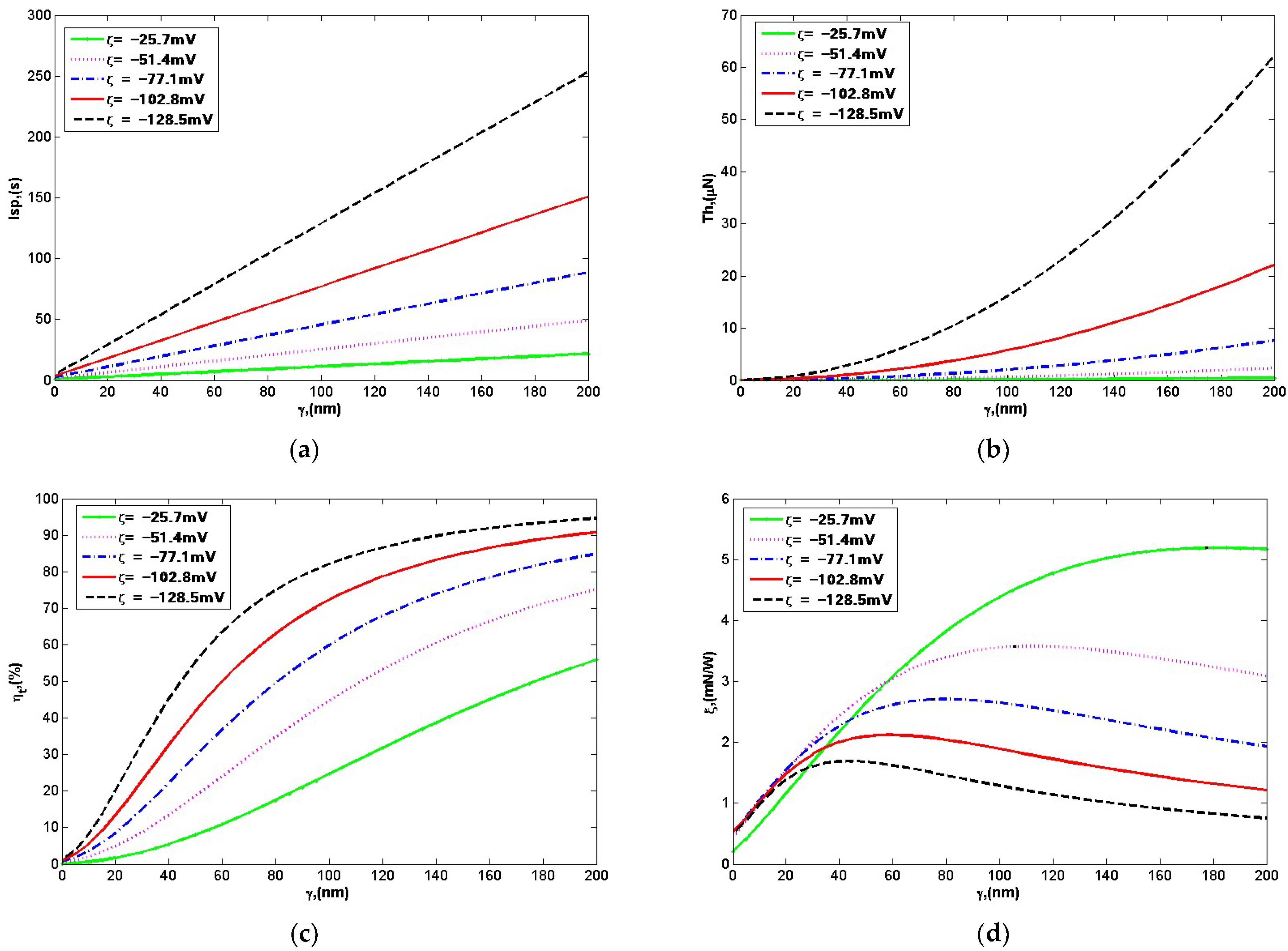
  • The high zeta potentials on the walls significantly promote the development of thruster thrust, specific impulse, and efficiency, but the thruster efficiency has the opposite effect.
  • For the real situation with the steric effect, thruster thrust and efficiency decrease to 5–30 micro Newtons and 80–90%, respectively, which takes a short specific impulse about 50–110 s.
  • The thrust-to-power ratio increases with the steric factor.
We are hopeful that these new conclusions obtained in the article can further provide a more theoretical basis for the space propulsion of micro/nano electrokinetic thrusters. However, various geometry and fluid environments present many challenges to thruster propulsion research, such as rectangular channels, and asymmetric and unsteady electric potential, which are worth being explored and surveyed in the future.

Author Contributions

Conceptualization, Y.J., J.Z. and S.A.; methodology, Y.J.; software, S.A.; validation, Y.J.; writing—original draft preparation, J.Z. and S.A.; writing—review and editing, Y.J., J.Z. and S.A.; supervision, Y.J. All authors have read and agreed to the published version of the manuscript.

Funding

This research was funded by the National Natural Science Foundation of China (grant No. 11772162), the Natural Science Foundation of Inner Mongolia Autonomous Region of China (grant No. 2021MS01007), and the Inner Mongolia Grassland Talent (grant No. 12000-12102408).

Acknowledgments

All authors are grateful to the reviewers for their constructive criticism, which helped to improve the paper tremendously.

Conflicts of Interest

The authors declare no conflict of interest.

Nomenclature

LLength of the channel, μm
WWidth of the channel, nm
HHeight of the channel, nm
eElementary electric charge, C
zValence number of ions, -
kBBoltzmann constant, J/K
n±Number densities of the electrolyte cations and anions, m−3
ExUniform axial electric field, V/m
TavAverage temperature, K
uStreamwise velocity along x-axis direction, m/s
n0Nominal ionic concentration in the bulk electrolyte reservoir, mol/L
g0The gravitational constant, m/s2
IspSpecific impluse of thrusters, s
ThThrust of thrusters, μN
Greek symbols
εrRelative permittivity, F/m
ε0Permittivity of the vacuum, F/m
νSteric factor, -
ζZeta potentials on the walls, mV
λThe EDL thickness, nm
μDynamic viscosity of the solution, Pa s
γThe coefficient of the slip boundary on the wall, nm
ρDensity of electrolyte, kg/m3
σElectrical conductivity of fluid, S/m
βCharacteristic parameter of the Joule heating, -
δCharacteristic parameter of the viscous frictional heating, -
ψElectric potential of fluid, V
ηtThruster efficiency, %
ξThrust-to-power ratio of thrusters, mN/W

References

  1. Wertz, J.R.; Larson, W.J. Reducing Space Mission Cost; Microcosm Press: El Segundo, CA, USA, 1992. [Google Scholar]
  2. Larson, W.J.; Wertz, J.R. Space Mission Analysis and Design; Microcosm Press: El Segundo, CA, USA, 1992. [Google Scholar]
  3. Mueller, J.; Chakraborty, I.; Bame, D.; Tang, W. Vaporizing liquid microthruster concept: Preliminary results of initial feasibility studies. In Micropropulsion for Small Spacecraft; AIAA: Reston, VA, USA, 2000; pp. 215–230. [Google Scholar]
  4. Wright, W.P.; Ferrer, P. Electric micropropulsion systems. Prog. Aerosp. Sci. 2015, 74, 48–61. [Google Scholar] [CrossRef]
  5. De Groot, W.A. Propulsion options for primary thrust and attitude control of microspacecraft, in Microsatellites as Research Tools. In COSPAR Colloquia Series Volume 10; Hsiao, F.-B., Ed.; Pergamon Press: Oxford, UK, 1999; pp. 200–209. [Google Scholar]
  6. Mueller, J. Thruster options for microspacecraft: A review and evaluation of existing hardware and emerging technologies. AIAA Paper 1997, 97, 3058. [Google Scholar]
  7. Krejci, D.; Lozano, P. Space Propulsion Technology for Small Spacecraft. IEEE Xplore 2018, 106, 362–376. [Google Scholar] [CrossRef] [Green Version]
  8. Martinez-Sanchez, M.; Pollard, J.E. Spacecraft electric propulsion—An overview. J. Propuls. Power 1998, 14, 688–699. [Google Scholar] [CrossRef] [Green Version]
  9. Filliben, J.D. Electric Thruster Systems; No. CPTR 97-65; Chemical Propulsion Information Agency: Columbia, MD, USA, 1997. [Google Scholar]
  10. Kramer, A.; Bangert, P.; Schilling, K. UWE-4: First Electric Propulsion on a 1U CubeSat—In-Orbit Experiments and Characterization. Aerospace 2020, 7, 98. [Google Scholar] [CrossRef]
  11. Levchenko, I.; Xu, S.; Teel, G.; Mariotti, D.; Walker, M.L.R.; Keidar, M. Recent Progress and perspectives of space electric propulsion systems based on smart nanomaterials. Nat. Commun. 2018, 9, 1–10. [Google Scholar] [CrossRef]
  12. Fujii, T. PDMS-based microfluidic devices for biomedical applications. Microelectron. Eng. 2002, 61–62, 907–914. [Google Scholar] [CrossRef]
  13. Wu, W.I.; Sask, K.N.; Brash, J.L.; Selvaganapathy, P.R. Polyurethane-based microfluidic devices for blood contacting applications. RSC. Lab Chip 2012, 12, 960–970. [Google Scholar] [CrossRef] [PubMed]
  14. McClain, M.A.; Culbertson, C.T.; Jacobson, S.C.; Allbritton, N.L.; Sims, C.E.; Ramsey, J.M. Microfluidic Devices for the High-Throughput Chemical Analysis of Cells. Am. Chem. Soc. Anal. Chem. 2003, 75, 5646–5655. [Google Scholar] [CrossRef] [PubMed]
  15. Stone, H.A.; Stroock, A.D.; Ajdari, A. Engineering flows in small devices: Microfluidics toward a lab-on-a- chip. Ann. Rev. Fluid. Mech. 2004, 36, 381–411. [Google Scholar] [CrossRef] [Green Version]
  16. Su, J.; Jian, Y.J.; Chang, L. Thermally fully developed electroosmotic flow through a rectangular microchannel. Int. J. Heat Mass Transf. 2012, 55, 6285–6290. [Google Scholar] [CrossRef]
  17. Miller, A.; Villegas, A.; Diez, F.J. Characterization of the startup transient electrokinetic flow in rectangular channels of arbitrary dimensions, zeta potential distribution, and time-varying pressure gradient. Electrophoresis 2015, 36, 692–702. [Google Scholar] [CrossRef] [PubMed]
  18. Yang, C.; Marcos; Wong, T.N.; Ooi, K.T. Dynamic aspects of electroosmotic flow in rectangular microchannels. Int. J. Eng. Sci. 2004, 42, 1459–1481. [Google Scholar]
  19. Rice, C.L.; Whitehead, R. Electrokinetic flow in a narrow cylindrical capillary. J. Phys. Chem. 1965, 69, 4017–4024. [Google Scholar] [CrossRef]
  20. Mala, G.M.; Li, D.; Werner, C.; Jacobasch, H.-J.; Ning, Y.B. Flow characteristics of water through a microchannel between two parallel plates with electrokinetic effects. Int. J. Heat Fluid Flow 1997, 18, 489–496. [Google Scholar] [CrossRef]
  21. Escandón, J.; Jiménez, E.; Hernández, C.; Bautista, O.; Méndez, F. Transient electroosmotic flow of Maxwell fluids in a slit microchannel with asymmetric zeta potentials. Eur. J. Mech. B Fluid 2015, 53, 180–189. [Google Scholar] [CrossRef]
  22. Levchenko, I.; Xu, S.; Mazouffre, S.; Lev, D.; Pedrini, D.; Goebel, D.; Garrigues, L.; Taccogna, F.; Bazaka, K. Perspectives, frontiers, and new horizons for plasma-based space electric propulsion. Phys. Plasmas 2020, 27, 1–18. [Google Scholar] [CrossRef] [Green Version]
  23. Huang, K.H.; Huang, H.-F. Two-liquid electroosmotic thrusters for micro propulsion applications. Phys. Fluids 2019, 31, 122003. [Google Scholar]
  24. Zheng, J.X.; Jian, Y.J. Electroosmotic thrusters in soft nanochannels for space propulsion. Phys. Fluids 2020, 32, 122005. [Google Scholar] [CrossRef]
  25. Zheng, J.X.; Jian, Y.J. Space Electroosmotic Thrusters in Ion Partitioning Soft Nanochannels. Micromachines 2021, 12, 777. [Google Scholar] [CrossRef] [PubMed]
  26. Banerjee, A.; Nayak, A.K. Influence of varying zeta potential on non-Newtonian flow mixing in a wavy patterned microchannel. J. Non-Newton. Fluid Mech. 2019, 269, 17–27. [Google Scholar] [CrossRef]
  27. Abdulhameed, M.; Muhammad, M.M.; Gital, A.Y.; Yakubu, D.G.; Khan, I. Effect of fractional derivatives on transient MHD flow and radiative heat transfer in a micro-parallel channel at high zeta potentials. Physica A 2019, 519, 42–71. [Google Scholar] [CrossRef]
  28. Peralta, M.; Arcos, J.; Méndez, F.; Bautista, O. Oscillatory electroosmotic flow in a parallel plate microchannel under asymmetric zeta potentials. Fluid Dyn. Res. 2017, 49, 035514. [Google Scholar] [CrossRef]
  29. Kang, Y.; Yang, C.; Huang, X. Electroosmotic flow in a capillary annulus with high zeta potentials. J. Colloid Interface Sci. 2002, 253, 285–294. [Google Scholar] [CrossRef] [PubMed]
  30. Nader Nekoubin; Electroosmotic flow of power-law fluids in curved rectangular microchannel with high zeta potentials. J. Non-Newton. Fluid Mech. 2018, 260, 54–68. [CrossRef]
  31. Mondal, M.; Misra, R.P.; De, S. Combined electroosmotic and pressure driven flow in a microchannel at high zeta potential and overlapping electrical double layer. Int. J. Therm. Sci. 2014, 86, 48–59. [Google Scholar] [CrossRef]
  32. Kilic, M.S.; Bazant, M.Z.; Ajdari, A. Steric effects in the dynamics of electrolytes at large applied voltages. I. Double-layer charging. Phys Rev. E 2007, 75, 021502. [Google Scholar] [CrossRef] [PubMed] [Green Version]
  33. Dey, R.; Ghonge, T.; Chakraborty, S. Steric-effect-induced alteration of thermal transport phenomenon for mixed electroosmotic and pressure driven flows through narrow confinements. Int. J. Heat Mass Transf. 2013, 56, 251–262. [Google Scholar] [CrossRef]
  34. Zheng, J.; Jia, B.; Jian, Y. Steric Effects on Space Electroosmotic Thrusters in Soft Nanochannels. Mathematics 2021, 9, 1916. [Google Scholar] [CrossRef]
  35. Jimenez, E.; Escandón, J.; Méndez, F.; Bautista, O. Combined viscoelectric and steric effects on the electroosmotic flow in nano/microchannels with heterogeneous zeta potentials. Colloids Surf. A 2019, 577, 347–359. [Google Scholar] [CrossRef]
  36. Jimenez, E.; Escandón, J.; Méndez, F.; Bautista, O. Combined viscoelectric and steric effects on the electroosmotic flow in a microchannel under induced high zeta potentials. Colloids Surf. A 2017, 531, 221–233. [Google Scholar] [CrossRef]
  37. Yeh, H.-C.; Chang, C.-C.; Yang, R.-J. Ion-size effect on electrokinetic energy conversion in nanofluidic channels. Int. J. Green Energy 2016, 13, 1050–1058. [Google Scholar] [CrossRef]
  38. Wicke, M.; Eigen, E.Z. The effect of space requirements of ions in aqueous solution on their distribution in the electric field and their activity coefficients. Electrochemistry 1952, 56, 551–561. [Google Scholar]
  39. Borukhov, I.; Andelman, D.; Orland, H. Adsorption of large ions from an electrolyte solution: A modified Poisson–Boltzmann equation. Electrochim. Acta 2000, 46, 221–229. [Google Scholar] [CrossRef] [Green Version]
  40. Khair, A.S.; Squires, T.M. Ion steric effects on electrophoresis of a colloidal particle. J. Fluid Mech. 2009, 640, 343–356. [Google Scholar] [CrossRef]
  41. Xing, J.N.; Jian, Y.J. Steric effects on electroosmotic flow in soft nanochannels. Meccanica 2018, 53, 135–144. [Google Scholar] [CrossRef]
  42. Andrews, J.; Das, S. Effect of finite ion sizes in electric double layer mediated interaction force between two soft charged plates. RSC Adv. 2015, 5, 46873–46880. [Google Scholar] [CrossRef]
  43. Sin, J.-S.; Kim, N.-H.; Kim, C.-H.; Jang, Y.-M. Influence of solvent polarization and non-uniform ionic size on electrokinetic transport in a nanochannel. Microfluid. Nanofluid. 2018, 22, 111. [Google Scholar] [CrossRef]
  44. Li, S.X.; Jian, Y.J.; Xie, Z.Y.; Liu, Q.S.; Li, F.Q. Rotating electro-osmotic flow of third grade fluids between two micro parallel plates. Colloids Surf. A Physicochem. Eng. Asp. 2015, 470, 240–247. [Google Scholar] [CrossRef]
  45. Goebel, D.M.; Katz, I. Fundamentals of Electric Propulsion: Ion and Hall Thrusters; John Wiley & Sons: Hoboken, NJ, USA, 2008. [Google Scholar]
  46. Hey, F.G. Micro Newton Thruster Development; Springer: Berlin/Heidelberg, Germany, 2017. [Google Scholar]
  47. Burgreen, D. Electrokinetic Flow in Capillary Elements; (Tech. Rep. AD0607212); United Nuclear Corporation: White Plains, NY, USA, 1963. [Google Scholar]
  48. Joseph, S.; Aluru, N.R. Hierarchical multiscale simulation of electrokinetic transport in silica nanochannels at the point of zero charge. Langmuir 2006, 22, 9041–9051. [Google Scholar] [CrossRef] [PubMed]
Figure 1. Schematic of a nanochannel in electroosmotic thrusters.
Mathematics 09 03222 g001
Figure 2. (a) The comparison of the dimensionless analytical velocity distribution of Jimenez and Escandón [35] and the present numerical velocity solution by setting dimensionless parameters: λ* = 0.2, γ* = 0, ζ* = −4.4, and ν = 0. The comparisons of (b) dimensionless specific impulse Isp*, (c) dimensionless thrust Th*, and (d) efficiency ηt of Huang and Huang [23] for the single layer and the present study results in the nanochannels with a high zeta potential and without steric effect.
Mathematics 09 03222 g002
Figure 3. The numerical velocity distribution of electroosmotic thrusters in nanochannels subjected to the wall zeta potential ζ with fixed parameters λ = 10 nm, γ = 0 nm, and ν = 0.
Mathematics 09 03222 g003
Figure 4. The numerical performance variations of (a) specific impulse Isp, (b) thrust Th, (c) efficiency ηt, and (d) thurst-to-power ratio ξ in nano electroosmotic thrusters with respect to the slip length γ for different wall zeta potentials ζ with fixed parameters for λ = 10 nm and ν = 0.
Mathematics 09 03222 g004
Figure 5. The numerical velocity distribution of the electroosmotic thrusters in the nanochannels subjected to the steric factor ν with fixed parameters for λ = 10 nm, γ = 0 nm, and ζ = −128.5 mV.
Mathematics 09 03222 g005
Figure 6. The numerical performance variations of (a) specific impulse Isp, (b) thrust Th, (c) efficiency ηt, and (d) thurst-to-power ratio ξ in nano electroosmotic thrusters with respect to the slip length γ for different the steric factors ν with fixed parameters λ = 10 nm and ζ = −128.5 mV.
Mathematics 09 03222 g006
Figure 7. The numerical variations of various energy items including (a) kinetic energy K, (b) Joule heating effect Pj, (c) viscous dissipation Pv, and (d) frictional heating Pf in nano electroosmotic thrusters with respect to the slip length γ for different the steric factors ν with fixed parameters λ = 10 nm and ζ = −128.5 mV.
Mathematics 09 03222 g007
Table 1. The convergence data of the program iteration regarding the electrical potential.
k351050
y
0.1−0.143872805826229−0.145417532697251−0.145417532791971−0.145417532791971
0.2−0.196629932339883−0.198721998552877−0.198721998680450−0.198721998680450
0.3−0.299074640117779−0.302203723477136−0.302203723666025−0.302203723666025
0.4−0.476051595345173−0.480856988922912−0.480856989207039−0.480856989207039
0.5−0.767108112561274−0.774180603445317−0.774180603844290−0.774180603844290
0.6−1.222541146714874−1.231394557318113−1.231394557776597−1.231394557776597
0.7−1.871662373169378−1.879650380343748−1.879650380736569−1.879650380736569
0.8−2.676684153937341−2.682026872785918−2.682026873052451−2.682026873052451
0.9−3.566560111123089−3.569107105193507−3.569107105321307−3.569107105321307
Publisher’s Note: MDPI stays neutral with regard to jurisdictional claims in published maps and institutional affiliations.

