Article

Mathematical Analysis of the Process Forces Effect on Collet Chuck Holders

Departamento de Ingeniería Mecánica, Universidad Carlos III de Madrid, Avda. de la Universidad, 30, 28911 Leganés-Madrid, Spain
*
Author to whom correspondence should be addressed.
Mathematics 2021, 9(5), 492; https://doi.org/10.3390/math9050492
Submission received: 15 January 2021 / Revised: 17 February 2021 / Accepted: 22 February 2021 / Published: 27 February 2021

Abstract

:
Chuck holders are widely used for jobs with high precision. A chuck holder consists of a nut with a tapered surface and a thin-slotted clamping sleeve typically made of hardened steel and named a collet. Chuck holders are, essentially, wedge mechanisms. In this paper, we investigated the reactions and strains due to the forces during the chip removal process in the contact elements or jaws of the collet by means of mathematical analysis. Deflections in the jaws of the collet arise with a high influence from the precision of the workpieces. The cutting or process forces cause an axial force, a radial force, a torsional moment, and a bending moment on the chuck collet, and, consequently, displacements and inclinations of the clamping system are caused. Therefore, the proposed analytical models are based on elasticity and contact theories. The mathematical model for determining the deflections of the clamping system force was developed and implemented using MATLAB. The results showed that the variation in the clamping force during rotation in a collet chuck holder mainly depends on the stiffness of the collet chuck holder and the stiffness of the workpiece. The results indicated that the collet should be vulcanized to minimize the deformations that affect the final product. The deflections of a collet chuck holder due to process forces depend strongly on the clearances, wedge angle, and stiffness of the collet.

1. Introduction

Collet chuck holders make it possible to clamp workpieces and tools uniformly. Generally, collet chuck holders attached to a machine tool are used to perform operations with close tolerances. As the spindle rotational speed of machine tools has been steadily increased due to the application of high-speed cutting technology, collet chuck holders must achieve high rotational speeds while maintaining good rotational accuracy. The majority of collet chuck holders use solid, thin-slotted clamping sleeves (collets) made of hardened steel and ground to a high degree of accuracy on their internal tapered and external cylindrical surfaces [1]. The clearance errors in the transmission systems of collet chuck holders due to the effectiveness of roughness and functional tolerances have been widely studied [2,3].
In the models proposed in the literature for jaw chucks [1,4,5,6,7] and collet chucks [3,8] based on rigid solid mechanics, the loss in clamping force is equal to the total centrifugal force at each one of the contact elements. However, the elastic strains in the contact elements make it possible that not all centrifugal force will reduce the clamping force, and even that part of centrifugal force may deform the clamping system [9,10,11,12]. Recently, authors have proposed analytical solutions and mathematical models to study the behavior of components and engineering elements [13,14,15,16,17].
In 1990, Fadyushin et al. [18], calculated the angular deflection caused by the torsional moment generated by the cutting forces in a Weldon system. In 1998, Rotberg et al. [19] carried out stiffness measurements in several Weldon systems. By using carbide rods of 12.7 mm diameter and 90 mm cantilever, they concluded that the stiffness of a Weldon system with two clamping bolts was approximately 15% lower than the stiffness of a fixed-fit tie-down system, whereas a Weldon with one clamping bolt had approximately 60% lower stiffness.
In 1999, Elderfeld and Hall [20] proposed a modified Weldon design for tool diameters between 6 and 12 mm based on the wedge effect, which achieved a higher clamping force than with traditional Weldon systems and, consequently, a more uniform pressure distribution. Fitz-Rite [21], in 2000, introduced a Weldon system, called “stub-length”, for end mills, in which the handle of the tool enters inside the conical part of the tool holder and is clamped by two screws, thus, reducing the overhang of the tool and increasing its rigidity.
Fadyushin et al. [18], and later Rotberg et al. [19], determined that the static stiffness of collet chuck holders was quite high, only 5% lower than monolithic fits; however, small changes in design and manufacture can translate into significant changes in stiffness. When it is necessary to achieve a high clamping force with collet chuck holders, the operating nut will cause a misalignment that will negatively affect the concentricity and distribution of clamping forces (see Figure 1). This effect is solved by collect chuck holders actuated pneumatically or hydraulically, which can be actuated by pulling or pushing [8,22] as shown in Figure 2.
The imbalance, due to the noncoincidence of the rotation axes of the workpiece and the collet contact elements with the main axis of inertia, strongly depends on the rotational speed and the eccentricity in the workpiece, which varies with the centering capacity of the collet chuck holder and with the displacement and inclination of the workpiece due to the action of the cutting force.
However, this approach has not been previously studied in the literature. This paper proposes a suitable, novel, mathematical model to determine the deformations of collet chuck holders and the contact elements of clamping collets due to the cutting forces during the chip removal process. In addition, the mathematical model is implemented in MATLAB.
The structure of the paper is as follows: first, we determine the loads on the collect contacts elements. Then, we determine the strains due to the radial forces and bending moments in Section 3 and Section 4, respectively. In Section 5, we summarize the results of the mathematical model. Finally, our conclusions are presented.

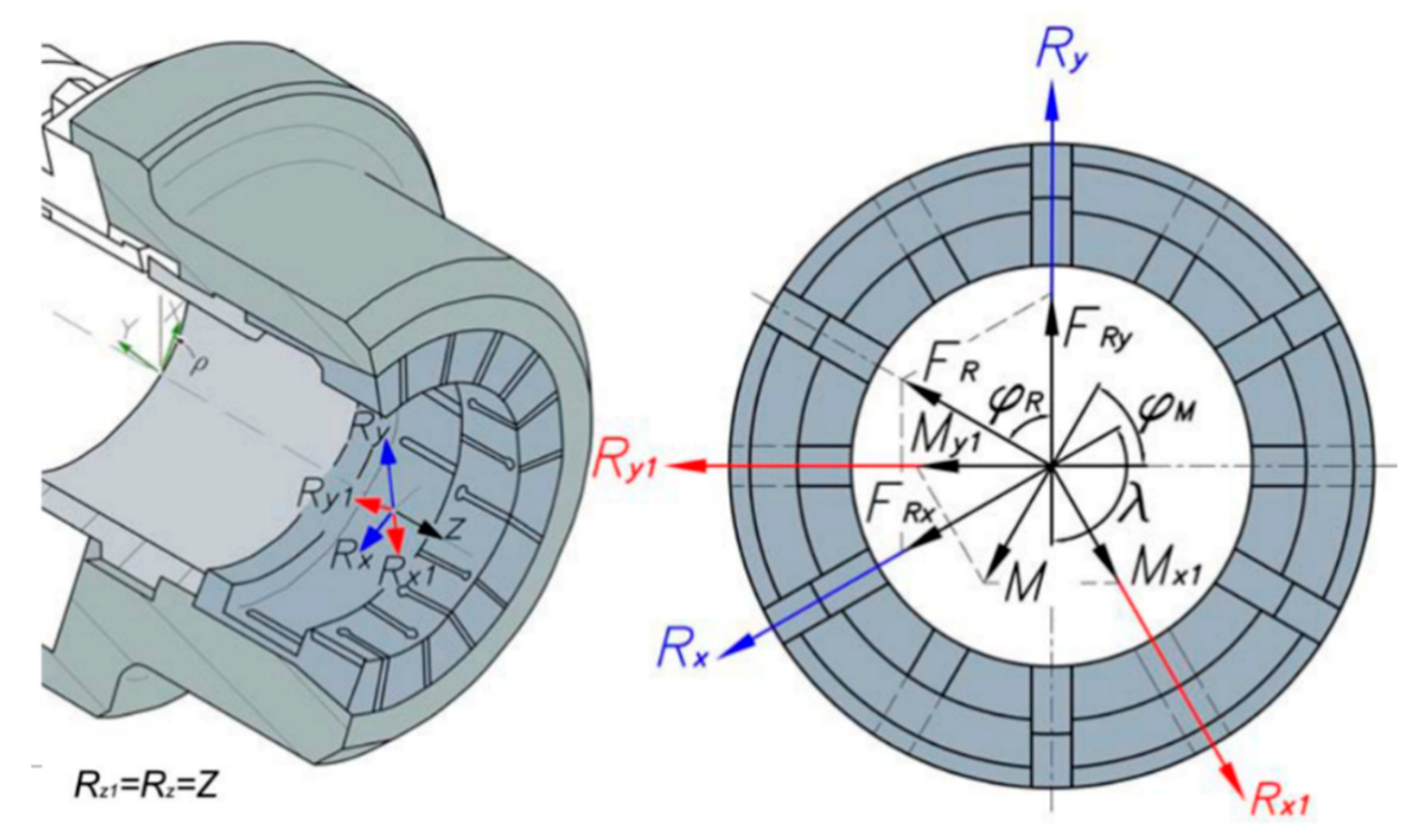
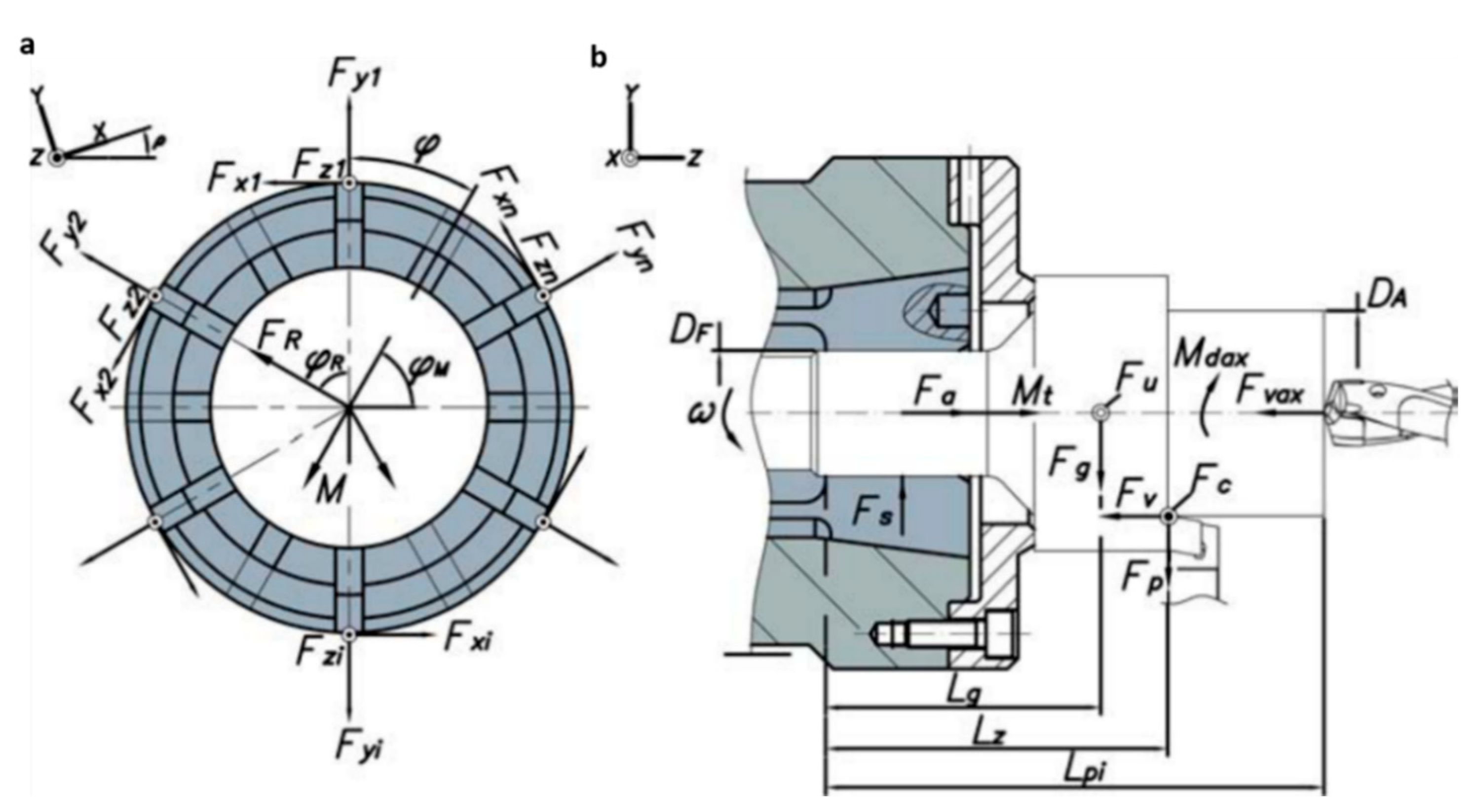
2. Determination of the Loads on the Collet Contact Elements

Cutting or process forces cause axial forces, radial forces, torsional moments, and bending moments on the collet chuck holders, and as a consequence, displacements and inclinations of the clamping systems are produced [12,23,24].
To represent the reactions at the collet contact elements, a global coordinate system (X, Y, Z) is defined, located in the spindle nose of the machine-tool and inclined by an angle, given by the inclination of the machine-tool bed. To represent the resultants of the combined loads acting on the workpiece, two coordinate systems are defined, (Rx, Ry, Rz) for the resultants in the radial direction, and (Rx1, Ry1, Rz1) for the moment components. For greater ease, the first coordinate system must be chosen taking advantage of the symmetries, while the second will be rotated 90° with respect to the first, as shown in Figure 3. We assumed that the axial loads are supported by the top of the collet chuck holder.
In Figure 3, FR is the resultant of the radial forces acting on the collet chuck holder, with FRx and FRy being its components according to the coordinate system, Rx, Ry, Rz as previously defined, where λ represents the angle between the chosen axes, and ρR is the angle that the resultant of the radial forces forms with the axis Ry. The components of the resultant of forces in the radial direction are expressed in Equation (1).
( F R x F R y )   =   ( F R ( cos ρ R + cos λ sin ρ R ) F R sin λ sin ρ R )
After rotating the coordinate system, (Rx, Ry, Rz) 90° counterclockwise (Figure 3), the components of the resultant of the bending moments, Mx1 and My1, caused by the radial force, FR, are represented in Equation (2), where ρM is the angle that the resultant of the bending moments forms with the axis Ry1.
( M x 1 M x 2 )   =   ( M ( cos ρ M + cos λ sin ρ M ) M sin λ sin ρ M )
To represent the reactions and strains, due to the forces during the chip removal process, in the contact elements or jaws of the collet, the local coordinate systems represented in Figure 4 are defined, where nc is the number of contacts or jaws of the collet. The stiffnesses of each of the contact elements of the collet in the direction of the local coordinate systems are kx, ky, and kz, which are obtained from the combination of the rigidity of the collet chuck holder kr1, kt1, and ka1 and from the radial stiffness of the workpiece kpi2, in Equations (3)–(5), where the workpiece has been assumed to be infinitely rigid in the tangential, kt1, and axial, ka1, directions.
k x   =   k t 1
k y   =   ( 1 k r 1 + 1 k p i 2 ) 1
k z   =   k a 1
In Figure 5b, the forces and moments acting on the workpiece are represented as well as in Figure 5a, the reaction forces and moments that appear on each contact surface at the contact elements or collet jaws, Fxi, Fyi, and Fzi. The values of the reactions with respect to the machine coordinate system, (X, Y, Z), where ρ represents the bed machine inclination, as shown in Figure 5a, are calculated by means of Equations (6)–(8).
F a   =   F v F v a x
M t   =   F c D A 2 + M d a x
F R   =   F R x 2 + F R y 2 + F u .
In Equations (6)–(8), Fa is the reaction in the machine due to the axial forces Fv and Fvax, which represent the feed forces of turning and drilling, respectively. Mt is the reaction in the spindle nose of the machine due to torsional moments caused by the main cutting force Fc and the drilling torque Mdax. FR is the reaction in the machine due to the radial forces considered, as shown in Figure 5, which are calculated using Equations (9) and (10), and the angle of rotation ωF, due to the rotation speed ω of the collet chuck holder, which is obtained by Equation (11), where φF0 is given by equation In Equations (9) and (10), Fg is the weight of the workpiece, χH is the position angle of the cutting tool and is given by the machine bed, Fc and Fp are the main and passive cutting forces, respectively, and ω is the rotation angle of the collet jaw.
F R x   =   F g cos ( ρ χ H ) ± F c
F R y   =   F p + F g sin ( ρ χ H )
φ F   =   φ F 0 φ ( π   φ π )
φ F 0   =   a r c t a n ( F R x F R y )
The reaction in the machine due to the bending moment M (Figure 5a), is calculated analytically using Equation (13), where the components Mx and My are obtained from Equations (14) and (15), respectively. The angle of rotation ωM, due to the rotation speed of the collet chuck holder is obtained by Equation (16), where the value of the initial angle ρM0 is calculated by means of Equation (17).
M   =   M x 2 + M y 2 + F u L g
M x   =   F g L g cos ( ρ χ H ) ± F c L z
M y   =   F p L z + F g L g sin ( ρ χ H )
φ M   =   φ M 0 φ ( π   φ π )
φ M 0   =   a r c t a n ( M x M y )
Before calculating the reactions at the collet jaws, the strains produced by the resultant of the radial forces, FR and the bending moments, M, in the directions represented in Figure 5a, must be calculated. The strains and, therefore, the reactions due to the resultant of the torsional moments are neglected, and the effect of the torsional moments produces workpiece unclamping. This has been widely studied [1,12]. Therefore, the torsional moment effects are very small with respect to those caused by the radial resultant and by the bending moments. The reactions in the axial direction are also not considered, since the resultant, Fa, is assumed by the top of the collet chuck holder.

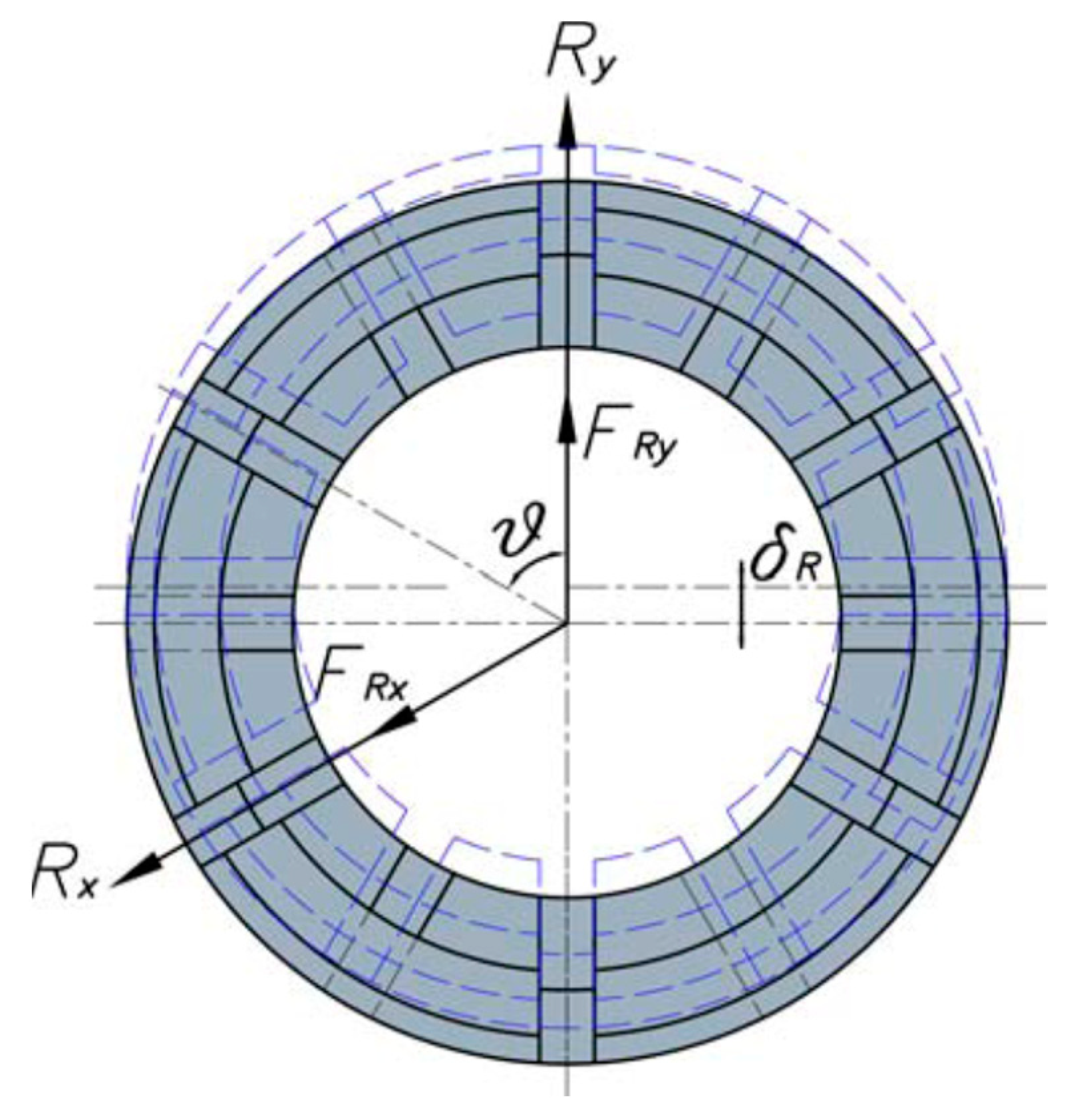
3. Strains by Radial Forces

The resultant radial component FRy causes a displacement δR in the direction of the axis Ry (Figure 6), which in turn causes reaction forces at the collet jaws (Figure 5a).
The balance of the forces condition is expressed by Equation (18), when it comes to collets with odd numbers of contacts or collet jaws, and expressed by Equation (19), when it comes to collets with even numbers of contacts or collet jaws. In the previous equations, nc is the number of collet jaws; kx and ky are the stiffness of each collet jaw, as shown in Figure 4; ϑ is the angle formed by the contact element or collet jaw with the axis Ry (see Figure 6).
F R y   =   δ R k y + ( n c 1 ) δ R k y cos 2 ϑ + ( n c 1 ) δ R k R sin 2 ϑ
F R y   =   2 δ R k y + ( n c 2 ) δ R k y cos 2 ϑ + ( n c 2 ) δ R k R sin 2 ϑ .
Therefore, the radial strain, δR, for odd numbers of collet jaws is given by Equation (20) and, for even number of contacts, it is given by Equation (21).
δ R   =   F R y 1 + ( n c 1 ) ( cos 2 ϑ + C sin 2 ϑ )   =   F R y k i 1
δ R   =   F R y 2 + ( n c 2 ) ( cos 2 ϑ + C sin 2 ϑ )   =   F R y k p 1
In Equations (20) and (21), C = kx/ky, ki, and kp are the result of grouping the denominators, respectively. Therefore, the reactions in the contact elements or collet jaws, represented in Figure 5, are obtained by Equation (22), for the case of collets with an even number of jaws, and by Equation (23), for collets with an odd number of jaws.
( F x 1 , F R y F y 1 , F R y F z 1 , F R y F x 2 , F R y F y 2 , F R y F z 2 , F R y F x i , F R y F y i , F R y F z i , F R y F x n c , F R y F y n c , F R y F z n c , F R y )   =   F R y ( 0 k p 1 0 k p 2 1 k p 2 1 0 0 k p ( n c 2 ) 1 0 k p ( n c 2 + 1 ) 1 k p ( n c 2 + 1 ) 1 0 k p n c 1 k p n c 1 0 )
( F x 1 , F R y F y 1 , F R y F z 1 , F R y F x 2 , F R y F y 2 , F R y F z 2 , F R y F x i , F R y F y i , F R y F z i , F R y F x n c , F R y F y n c , F R y F z n c , F R y )   =   F R y ( 0 k i 1 0 k i 2 1 k i 2 1 0 k i i 1 k i i 1 0 k i n c 1 k i n c 1 0 )
For the radial component, FRx in the direction of the Rx axis (Figure 5), is obtained by the same reasoning, Equations (24) and (25), for an even and odd number of jaws, respectively.
( F x 1 , F R x F y 1 , F R x F z 1 , F R x F x 2 , F R x F y 2 , F R x F z 2 , F R x F x i , F R x F y i , F R x F z i , F R x F x n c , F R x F y n c , F R x F z n c , F R x )   =   F R x ( k p 1 k p 1 0 k p 2 1 k p 2 1 0 k p i 1 0 0 k p ( i + 1 ) 1 k p ( i + 1 ) 1 0 k p n c 1 k p n c 1 0 )
( F x 1 , F R x F y 1 , F R x F z 1 , F R x F x 2 , F R x F y 2 , F R x F z 2 , F R x F x i , F R x F y i , F R x F z i , F R x F x n c , F R x F y n c , F R x F z n c , F R x )   =   F R x ( k i 1 k i 1 0 k i 2 1 k i 2 1 0 k i i 1 0 0 k i ( i + 1 ) 1 k i ( i + 1 ) 1 0 k i ( i + n c 2 ) 1 0 0 k i ( n c 2 + 1 ) 1 k i ( n c 2 + 1 ) 1 0 k i n c 1 k i n c 1 0 )

4. Strains by Bending Moments
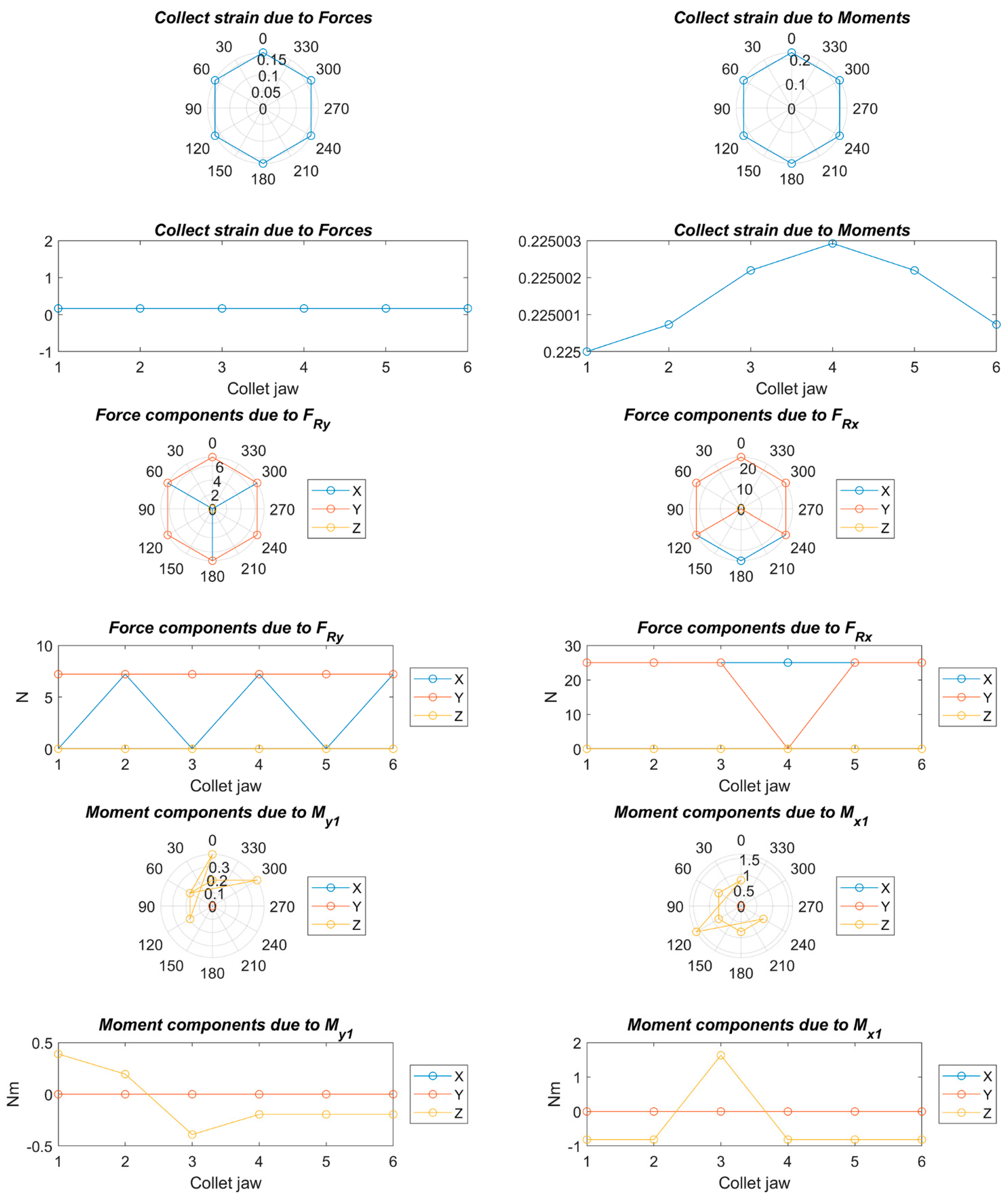
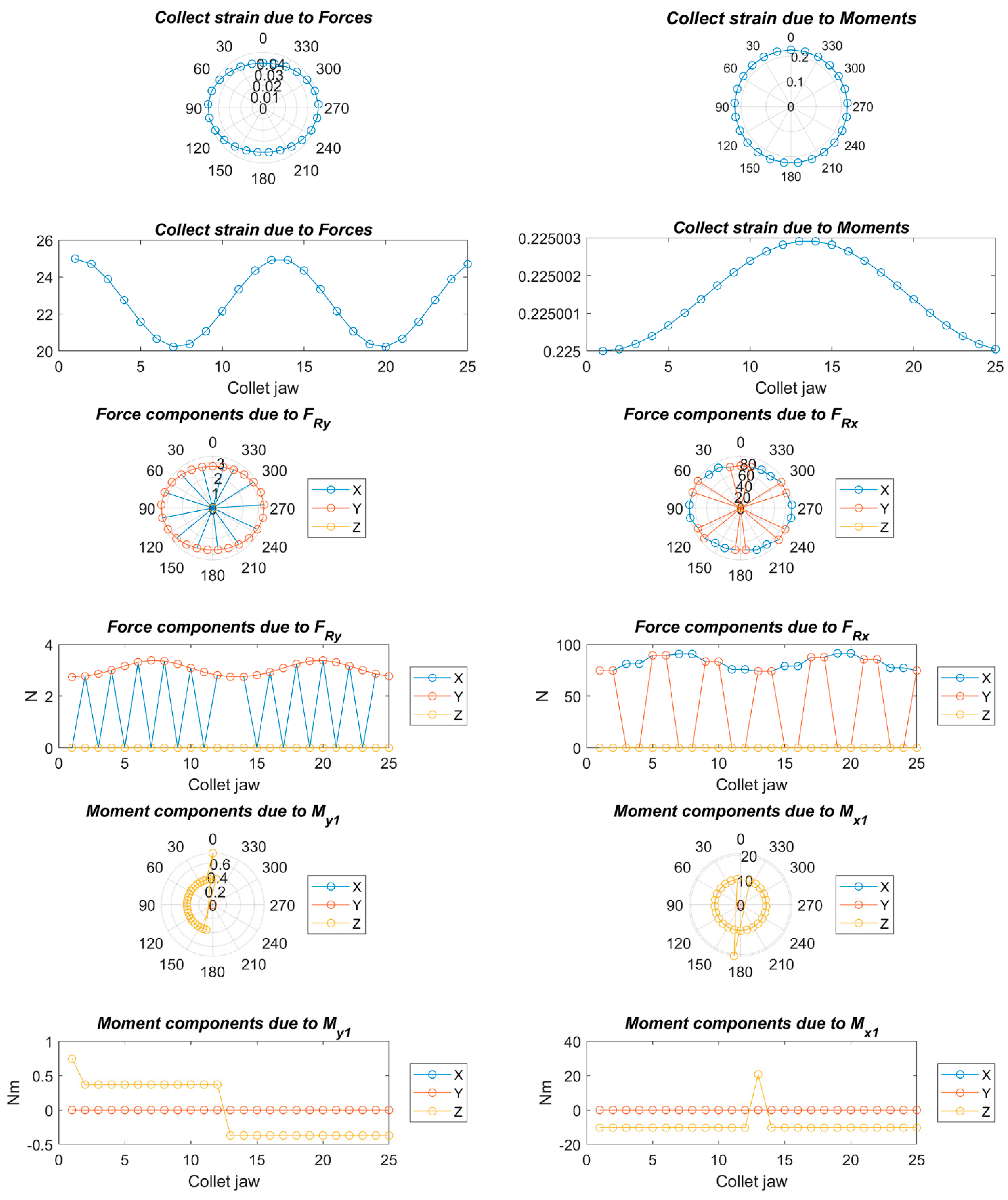
The components My1 and Mx1 of the resulting bending moment M, according to the Ry1 and Rx1 coordinate system, cause inclinations in the workpiece. These inclinations, in turn, produce a static friction force Fk on the contact elements or collet jaws (see Figure 7).
The relative displacement δF, between the different contact elements or claws of the clamp (Figure 7), is calculated using Equation (26), where kz is the stiffness of the contact elements or collet jaws in Z direction (see Figure 4).
δ F   =   F k k z + F k 2 k z   =   3 F k 2 k z   =   d i D F Ω .
The friction force Fk, is calculated with Equation (27).
F k   =   3 D F Ω k z 2
The inclination of the workpiece produces a spacing in the axial direction Δl1i (Figure 7) between the collet jaws. This spacing comes from the variation in the length of each collet jaw Δl. The angle of inclination in each of the collet jaws, Ωi, will be equal to the angle of inclination due to the workpiece, Ω, affected by the stiffness of the collet chuck holder, kr,T, due to the clamping force Fs, [1,8,12,22,23], in Equations (28)–(30), and In Equations (28) and (29), collets that do not have a symmetric contact element or jaw are above the symmetry axis of the collet. For the opposite case, Equations (30) and (31) must be used. These equations have not considered the variation that the elongation, Δli, causes in the stiffness of the collet chuck, kr,T.
Ω i   =   Ω
Ω i   =   F s Δ l i k r , T
Ω i ( n c i )   =   Ω 2
Ω i ( n c i )   =   F s Δ l i ( n c i ) k r , T
By means of Equations (32) and (33), elongation values are obtained for collets without symmetrical contact elements or jaws and with symmetric contact elements or jaws, respectively.
Δ l i   =   k r , T Ω F s
Δ l i ( n c i )   =   3 k r , T Ω 2 F s
Therefore, the elongation, Δl1i, between the two jaws of the collet is calculated by Equation (34).
Δ l 1 i   =   Δ l 1 + Δ l i ( n c i )   =   3 2 k r , T F s
Therefore, the component along the Ry1 axis of the resulting bending moment, M (Figure 7), is obtained by Equation (35).
M y 1   =   F s Δ l 1 i + F k d i D F
Therefore, substituting the angle of inclination of the workpiece Ω in Equation (35) is obtained in Equation (36).
Ω   =   2 M y 1 3 k r , T + 2 k z d i D F 2
The reactions in the collet jaws due to the component My1 of the resulting bending moment M, represented in Figure 7, are obtained by means of Equation (37), for collets with an odd number of jaws, and by means of Equation (38), for collets with an even number of jaws. In Equations (37) and (38), ζ, the grouping of terms from Equation (36) is in Equation (39).
( F x 1 , M y 1 F y 1 , M y 1 F z 1 , M y 1 F x 2 , M y 1 F y 2 , M y 1 F z 2 , M y 1 F x i , M y 1 F y i , M y 1 F z i , M y 1 F x n c , M y 1 F y n c , M y 1 F z n c , M y 1 )   =   M y 1 ( 0 0 2 ς i 1 1 0 0 ς i 2 1 0 0 2 ς i i 1 0 0 ς i n c 1 )
( F x 1 , M y 1 F y 1 , M y 1 F z 1 , M y 1 F x 2 , M y 1 F y 2 , M y 1 F z 2 , M y 1 F x i , M y 1 F y i , M y 1 F z i , M y 1 F x n c , M y 1 F y n c , M y 1 F z n c , M y 1 )   =   M y 1 ( 0 0 2 ς p 1 1 0 0 ς p 2 1 0 0 2 ς p i 1 0 0 ς p n c 1 )
ζ   =   2 3 k r , T + 2 k z d i D F 2
By the same reasoning previously exposed, reactions in the contact elements or collet jaws due to the component Mx1 are obtained with Equations (40) and (41), for the cases of odd and even jaws, respectively.
( F x 1 , M x 1 F y 1 , M x 1 F z 1 , M x 1 F x 2 , M x 1 F y 2 , M x 1 F z 2 , M x 1 F x i , M x 1 F y i , M x 1 F z i , M x 1 F x n c , M x 1 F y n c , M x 1 F z n c , M x 1 )   =   M x 1 ( 0 0 ς i 1 1 0 0 ς i 2 1 0 0 2 ς i i 1 0 0 ς i n c 1 )
( F x 1 , M x 1 F y 1 , M x 1 F z 1 , M x 1 F x 2 , M x 1 F y 2 , M x 1 F z 2 , M x 1 F x i , M x 1 F y i , M x 1 F z i , M x 1 F x n c , M x 1 F y n c , M x 1 F z n c , M x 1 )   =   M x 1 ( 0 0 ς p 1 1 0 0 ς p 2 1 0 0 2 ς p i 1 0 0 ς p n c 1 )

5. Results

In the analytical model presented, the strains due to torsional moments were not regarded, since their effect was considered negligible compared to the effects of the bending moments.
The cutting forces were taken, for an orthogonal cutting process, from Criado et al. [25] and, for an oblique cutting, from Moufki et al. and Sutter et al. [26,27]. The used values are shown in Table 1. The collet diameter, DF, is 0.03 m, the chuck holder and collet stiffness, kr,T and kz, respectively, are taken from Namazi et al. [23] as 0.15 and 0.065 N/m. The radial reactions and moments are summarized in Table 2.

5.1. Strains Due to Radial Forces

The strains due to the radial forces in each contact element or collet jaw were analytically determined by means of Equations (20) and the reaction forces in the radial direction were analytically calculated using Equations (18) and The contact stiffness between the collet jaws and workpiece, in the radial and axial directions, was determined using the finite element model widely described by Soriano et al. [12] and Namazi et al. [23]. The rest of the parameters were obtained from the geometry of the tested clamping collet.
The radial process forces are the cutting force (FC) and the weight (Fg) as is shown in Figure 5b. The values of these forces are introduced in Equations (18) and (19) to obtain the reactions in the case of odd and even numbers of jaws, respectively. As it was mentioned above, the axial forces (Fa) are supported by the collet chuck holder. The previous model was implemented in MATLAB, as shown in Figure 8, Figure 9, Figure 10, Figure 11, Figure 12, Figure 13, Figure 14 and Figure 15.

5.2. Strains due to Bending Moments

The relative strains in the contact elements or collet jaws of the collet chuck due to the bending moments caused by the process forces were analytically determined by means of Equation (26), and the parameters that intervene in the mentioned equation were calculated by means of the Equations (28)–(36).The total stiffness of the system, krT, was determined as in the case of the influence of the centrifugal force [9,12,23,24], while the axial stiffness, kz, was determined using the finite element model widely described [3,8,12,22,23]. This model was also implemented in MATLAB, as shown in Figure 8, Figure 9, Figure 10, Figure 11, Figure 12, Figure 13, Figure 14 and Figure 15.

5.3. Total Strains

Figure 8, Figure 9, Figure 10, Figure 11, Figure 12, Figure 13, Figure 14 and Figure 15 show the deformation due to the bending moments and radial forces of the collet caused by the forces during the chip removal process. The deviation of the center of the collet depends on chuck holder stiffness: the higher the stiffness of the collet chuck holder the lower the deviation due to the high load and high turning speed. This center variation has a decisive influence on the centering capacity of the system and, consequently, on the concentricity in the final product.
On the other hand, a strong deformation was observed at the upper and lateral sides of the collet, which will cause a decrease in the clamping force at the upper side and an increase in the clamping force at the lateral side. This will greatly affect the cylindricity in the final product.

6. Conclusions

In this work, an analytical model was presented to determine the process forces effect on collet chuck holders, in which the process forces depend strongly on the clearances, wedge angle, and collet stiffness.
The different effects on the variation of the clamping force due to the process forces that act on the drive system and collet jaws were modeled with different stiffness factors.
The results showed that the variation in the clamping force during rotation in a collet chuck holder depended on:
  • The stiffness of the collet chuck holder, and thus the equipment that presents a lower structural rigidity will reduce the variations in the clamping force due to the centrifugal forces caused by a high rotational speed.
  • The stiffness of the workpiece is always satisfied when the workpiece is more rigid than the contact elements or collet jaws, which is fulfilled in the case of metal workpieces. In less common cases, in which the workpiece is less rigid than the contact elements or collet jaws, the rotational speed has no influence.
  • It is important that the collet stiffness is uniform to minimize the deformations that affect the final product. For this reason, it is very common to use vulcanized collets.
The results of this work could be implemented in future collet chuck holders that compensate for the jaw deformations to manufacture a better quality product.

Author Contributions

Individual contributions are as follows: introduction, methodology, visualization, and original draft preparation: E.S.-H., H.R., and A.B.; review, editing, validation, and formal analysis: E.S.-H., H.R., and C.C.; supervision: C.C. All authors have read and agreed to the published version of the manuscript.

Funding

This research received no external funding.

Institutional Review Board Statement

Not applicable.

Informed Consent Statement

Not applicable.

Data Availability Statement

Not applicable.

Conflicts of Interest

The authors declare no conflict of interest.

References

  1. VDI-Fachbereich Produktionstechnik und Fertigungsverfahren VDI 3106: Determination of permissible speed (rpm) of lathe chucks (jaw chucks). In VDI manual Production Technology and Manufacturing Methods—Volume 3: Production Equipment; VDI-Gesellschaft Produktion und Logistik: Düsseldorf, Germany, 2004.
  2. Anselmetti, B. Generation of functional tolerancing based on positioning features. Comput. Des. 2006, 38, 902–919. [Google Scholar] [CrossRef]
  3. Soriano, E.; Rubio, H.; García-Prada, J.C. Analysis of the clamping mechanisms of collet chucks holders for turning. In New Trends in Mechanism and Machine Science; Springer: Dordrecht, The Netherlands, 2013; Volume 7, pp. 391–398. [Google Scholar] [CrossRef]
  4. Nyamekye, K.; Mudiam, S.S. A model for predicting the initial static gripping force in lathe chucks. Int. J. Adv. Manuf. Technol. 1992, 7, 286–291. [Google Scholar] [CrossRef]
  5. Rahman, M.; Tsutsumi, M. Effect of spindle speed on clamping force in turning. J. Mater. Process. Technol. 1993, 38, 407–415. [Google Scholar] [CrossRef]
  6. Ema, S.; Marui, E. Chucking Performance of a Wedge-Type Power Chuck. Trans. ASME J. Eng. Ind. 1994, 116, 70–77. [Google Scholar] [CrossRef]
  7. Rivin, E.I.; Agapiou, J.; Brecher, C.; Clewett, M.; Erickson, R.; Huston, F.; Kadowaki, Y.; Lenz, E.; Moriwaki, T.; Pitsker, A.; et al. Tooling Structure: Interface between Cutting Edge and Machine Tool. CIRP Ann. 2000, 49, 591–634. [Google Scholar] [CrossRef]
  8. Soriano, E.; Rubio, H.; García-Prada, J.C. Models for Determining the Static Stiffness of Collet Sleeves. In New Advances in Mechanisms, Transmissions and Applications; Springer: Dordrecht, The Netherlands, 2014; Volume 17, pp. 375–383. [Google Scholar]
  9. Xu, C.; Zhang, J.; Wu, Z.; Yu, D.; Feng, P. Dynamic modeling and parameters identification of a spindle–holder taper joint. Int. J. Adv. Manuf. Technol. 2013, 67, 1517–1525. [Google Scholar] [CrossRef]
  10. Xu, C.; Zhang, J.; Feng, P.; Yu, D.; Wu, Z. Characteristics of stiffness and contact stress distribution of a spindle–holder taper joint under clamping and centrifugal forces. Int. J. Mach. Tools Manuf. 2014, 82–83, 21–28. [Google Scholar] [CrossRef]
  11. Liu, G.; Hong, J.; Wu, W.; Sun, Y. Investigation on the influence of interference fit on the static and dynamic characteristics of spindle system. Int. J. Adv. Manuf. Technol. 2018, 99, 1953–1966. [Google Scholar] [CrossRef]
  12. Heras, E.S.; Rubio, H.; Bustos, A.; García Prada, J.C. Automatic Expanding Mandrel with Air Sensing Device: Design and Analysis. Appl. Sci. 2020, 10, 2551. [Google Scholar] [CrossRef] [Green Version]
  13. Mai, T.D.; Ryu, J. Effects of Leading-Edge Modification in Damaged Rotor Blades on Aerodynamic Characteristics of High-Pressure Gas Turbine. Mathematics 2020, 8, 2191. [Google Scholar] [CrossRef]
  14. Liang, Z.; Cui, C.; Meng, K.; Xin, Y.; Pei, H.; Li, H. New Analytical Solutions for Longitudinal Vibration of a Floating Pile in Layered Soils with Radial Heterogeneity. Mathematics 2020, 8, 1294. [Google Scholar] [CrossRef]
  15. Fetecau, C.; Ellahi, R.; Sait, S.M. Mathematical Analysis of Maxwell Fluid Flow through a Porous Plate Channel Induced by a Constantly Accelerating or Oscillating Wall. Mathematics 2021, 9, 90. [Google Scholar] [CrossRef]
  16. Rezvani, S.; Kim, C.-J.; Park, S.S.; Lee, J. Simultaneous Clamping and Cutting Force Measurements with Built-In Sensors. Sensors 2020, 20, 3736. [Google Scholar] [CrossRef]
  17. Santos, E.; Richter, H. Design and Analysis of Novel Actuation Mechanism with Controllable Stiffness. Actuators 2019, 8, 12. [Google Scholar] [CrossRef] [Green Version]
  18. Fadyushin, I.L.; Musykant, Y.A.; Messheryakov, A.I. Tooling for cnc machine tool. Mashinostorenie Publ. 1990. [Google Scholar]
  19. Rotberg, J.; Lenz, E.; Levin, M. Drill and clamping interface in high-performance drilling. Int. J. Adv. Manuf. Technol. 1998, 14, 229–238. [Google Scholar] [CrossRef]
  20. X-tra Long Tool Holders, Elderfield & Hall: Knoxville, TN, USA, 1999.
  21. V-Flange Holders, Fitz-Rite Products, Inc.: Troy, MI, USA, 2000.
  22. Soriano, E.; Ramirez, M.B.; Rubio, H. Model for determining the clamping force in expanding mandrels for high-speed turning. Int. Rev. Mech. Eng. 2012, 6, 384–389. [Google Scholar]
  23. Namazi, M.; Altintas, Y.; Abe, T.; Rajapakse, N. Modeling and identification of tool holder–spindle interface dynamics. Int. J. Mach. Tools Manuf. 2007, 47, 1333–1341. [Google Scholar] [CrossRef]
  24. Xu, C.; Zhang, J.; Yu, D.; Wu, Z.; Feng, P. Dynamics prediction of spindle system using joint models of spindle tool holder and bearings. Proc. Inst. Mech. Eng. Part C J. Mech. Eng. Sci. 2015, 229, 3084–3095. [Google Scholar] [CrossRef]
  25. Criado, V.; Feito, N.; Cantero Guisández, J.L.; Díaz-Álvarez, J. A New Cutting Device Design to Study the Orthogonal Cutting of CFRP Laminates at Different Cutting Speeds. Materials (Basel) 2019, 12, 4074. [Google Scholar] [CrossRef] [Green Version]
  26. Moufki, A.; Devillez, A.; Dudzinski, D.; Molinari, A. Thermomechanical modelling of oblique cutting and experimental validation. Int. J. Mach. Tools Manuf. 2004, 44, 971–989. [Google Scholar] [CrossRef]
  27. Sutter, G.; Molinari, A. Analysis of the Cutting Force Components and Friction in High Speed Machining. J. Manuf. Sci. Eng. 2005, 127, 245–250. [Google Scholar] [CrossRef]
Figure 1. Manual collet chucking system.
Mathematics 09 00492 g001
Figure 2. Automatic collet chucking systems. (a) Acting by pushing. (b) Acting by pulling.
Mathematics 09 00492 g002
Figure 3. Coordinate systems and the resultants of the forces and moments.
Mathematics 09 00492 g003
Figure 4. Coordinate systems and jaw stiffnesses.
Mathematics 09 00492 g004
Figure 5. (a) Reaction forces at the collet jaws. (b) Forces and moments generated at the collet jaws.
Mathematics 09 00492 g005
Figure 6. Radial deformation.
Mathematics 09 00492 g006
Figure 7. Bending moment deformation and friction forces.
Mathematics 09 00492 g007
Figure 8. Strains, forces, and moments; Fa = 90 N, Fc = 125 N, Fp = 0 N, nc = 5, and C = 1.
Mathematics 09 00492 g008
Figure 9. Strains, forces, and moments; Fa = 90 N, Fc = 125 N, Fp = 0 N, nc = 6, and C = 1.
Mathematics 09 00492 g009
Figure 10. Strains, forces, and moments; Fa = 90 N, Fc = 125 N, Fp = 0 N, nc = 25, and C = 0.8.
Mathematics 09 00492 g010
Figure 11. Strains, forces, and moments; Fa = 90 N, Fc = 125 N, Fp = 0 N, nc = 30, and C = 1.2.
Mathematics 09 00492 g011
Figure 12. Strains, forces, and moments; Fa = 1042 N, Fc = 1800 N, Fp = 56 N, nc = 5, and C = 1.
Mathematics 09 00492 g012
Figure 13. Strains, forces, and moments; Fa = 1042 N, Fc = 1800 N, Fp = 56 N, nc = 6, and C = 1.
Mathematics 09 00492 g013
Figure 14. Strains, forces, and moments; Fa = 1042 N, Fc = 1800 N, Fp = 56 N, nc = 27, and C = 0.8.
Mathematics 09 00492 g014
Figure 15. Strains, forces, and moments; Fa = 1042 N, Fc = 1800 N, Fp = 56 N, nc = 30, and C = 1.2.
Mathematics 09 00492 g015
Table 1. The process forces and collet parameters.
ProcessFa(N)
Feed Force
Fc = Fu(N)
Cutting Force
Fp(N)
Thrust Force
Fg
(N)
Weight
Mdax (Nm)
Drilling Torque
χH
Machine Bed Angle
nc
Collet Jaws
ρ = ϑ
Collet Jaws Angle
C = kx/ky
Stiffness Relation
Lg(m)
Gravity Center
Lz(m)
Application Point
MinMaxMinMaxMinMaxMinMax
Orthogonal90440125205005000057210.020.025
90440125205005000066010.020.025
9044012520500500002514.400.80.020.025
90440125205005000030121.20.020.025
Oblique5031042758180017565000057210.020.025
5031042758180017565000066010.020.025
503104275818001756500002514.400.80.020.025
5031042758180017565000030121.20.020.025
Table 2. The reactions and moments.
ProcessFRx (N)FRy (N)Mx1 (Nm)My1 (Nm)
MinMaxMinMaxMinMaxMinMax
Orthogonal140.45220.4547.5547.553.435.430.950.95
15023043.3043.303.635.630.870.87
173.43253.6512.4311.534.096.100.250.23
173.91253.9110.4010.404.106.100.210.21
Oblique773.451815.4564.55103.5519.2645.311.382.35
783182560.3099.3019.4545.51.292.27
806.651848.425.5368.4319.9245.970.661.65
806.911848.927.4066.4019.9345.980.631.61
Publisher’s Note: MDPI stays neutral with regard to jurisdictional claims in published maps and institutional affiliations.

