

Surface Plasmon Electrochemistry: Tutorial and Review
1
Department of Physics, University of Ottawa, 150 Louis Pasteur, Ottawa, ON K1N 6N5, Canada
2
NEXQT Institute, University of Ottawa, 25 Templeton St., Ottawa, ON K1N 6N5, Canada
3
School of Electrical Engineering and Computer Science, University of Ottawa, 25 Templeton St., Ottawa, ON K1N 6N5, Canada
*
Author to whom correspondence should be addressed.
Chemosensors 2023, 11(3), 196; https://doi.org/10.3390/chemosensors11030196
Submission received: 9 February 2023
/
Revised: 13 March 2023
/
Accepted: 16 March 2023
/
Published: 19 March 2023
(This article belongs to the Special Issue Recent Developments in Electrochemical Sensing)
Abstract
:Surface plasmon polaritons (SPPs) are optical surface waves propagating along a metal surface. They exhibit attributes such as field enhancement and sub-wavelength localization, which make them attractive for surface sensing, as they are heavily exploited in surface plasmon biosensors. Electrochemistry also occurs on metal surfaces, and electrochemical techniques are also commonly applied in biosensors. As metal surfaces are integral in both, it is natural to combine these techniques into a single platform. Motivations include: (i) realising a multimodal biosensor (electrochemical and optical), (ii) using SPPs to probe the electrochemical double layer or to probe electrochemical activity, thus revealing complementary information on redox reactions, or (iii) using SPPs to pump electrochemical reactions by creating non-equilibrium energetic electrons and holes in a working electrode through the absorption of SPPs thereon. The latter is of interest as it may yield novel redox reaction pathways (i.e., plasmonic electrocatalysis).
1. Introduction
Analyzing biomolecules is required in many fields, ranging from food safety inspection to medical diagnostics [1,2,3]. Many labelled detection methods have been used to detect biomolecules. These labeled detection techniques include enzyme-linked immunosorbent assay (ELISA) [4,5], colorimetric and fluorescence detection [6,7,8], polymerase chain reaction (PCR) [9,10], radioactive isotopes (radio-immunoassays) [11], vibrational spectroscopy (e.g., infrared and Raman spectroscopy) [12], and some other techniques [13,14]. Labelled techniques generally create problems due to the use of labels, e.g., the interference of fluorophores with binding kinetics, or changes in fluorescence dynamics due to dye–protein interactions [15]. Problems such as these do not exist in label-free methods to detect biomolecules, such as mass spectrometry (MS) [16], quartz crystal microbalance (QCM) techniques [17], surface plasmon resonance (SPR) [18] or localized surface plasmon resonance (LSPR) [19] techniques, and methods based on long-range surface plasmon polaritons (LRSPPs) [20] or the anomalous reflection from gold [21].
A biosensor is a transduction device that is used to measure biological or biochemical reactions by generating quantitative signals (electrical, thermal, optical) proportional to the concentration of an analyte [2,22,23]. A biosensor has a recognition element (e.g., enzymes, nucleic acids, cells, and micro-organisms or antibodies) to selectively capture the analyte of interest in a sample. Depending on the underlying transducer technology, one can identify several types of biosensors: electrochemical [24,25], piezoelectric [26,27], thermal [28], and optical [29].
The most common type of biosensor is electrochemical [30,31,32,33]. Electrodes have an essential role as solid support for the immobilization of biomolecules and electron transfer to/from the redox species. As a result of certain electroactive species undergoing a redox reaction in the system, a voltage or a current is generated. One of the critical aspects of an electrochemical biosensor is the use of enzymes as predominant recognition elements due to their specific binding capabilities and biocatalytic activity [31,32]. In this sensing method, different electrochemical detection techniques such as amperometric, potentiometric, and conductometric techniques are used [33].
QCM biosensors exploit the piezoelectric effect and are the most widespread example of a piezoelectric sensor [34]. In such biosensors, changes in accumulated surface mass density change the resonant frequency, which is monitored in real time, while sensing in gaseous or fluidic environments [35].
Thermometric biosensors use thermometry (measurement of temperature) to monitor biochemical interactions, using, for instance, a thermometer [28] or sensitive thermistors [36], as heat-producing biochemical absorption takes place. Thermometry has also been integrated with ELISA in a new method known as thermometric ELISA (TELISA) [37,38].
Optical biosensors measure an optical parameter such as absorption or refractive index associated with surface mass loading resulting from biomolecular interaction, optical emission such as fluorescence emitted by a label, or Raman scattering specific to a molecular species [39,40,41]. Optical biosensors can provide highly sensitive, direct, real-time, and label-free detection of many biological and chemical substances [42]. Optical biosensors operate in label-based or label-free mode [42]. In label-based sensors, a fluorescent label is used, and the optical emission produced (or quenched) by a biochemical reaction is monitored. In label-free devices, the detected signal is generated directly by the interaction of the analyte with recognition elements immobilized on the transducer surface [42]. There are different varieties of optical biosensors, such as optrode fibre optics, evanescent-wave waveguides, flow immunosensors, and SPR.
Surface plasmon polaritons (SPPs) are optical surface waves propagating at the interface between a metal and a dielectric. Biosensors based on SPPs are among the most studied and used because of the large overlap of SPPs with an adlayer forming on the metal, and their large surface fields [43]. These features make SPPs very sensitive to changes in the refractive index near the metallic surface. However, propagation losses associated with the absorption of light in the metal is a limitation. This problem can be addressed using symmetric structures based on a thin metal layer to support long-range SPPs (LRSPPs) [44]. LRSPPs require that the top and bottom claddings have a similar index of refraction. Biosensing occurs in an aqueous environment, which limits the choice of materials for the bottom cladding to, for example, low-index polymers such as Teflon or Cytop [20]. The use of such polymers imposes limitations during the fabrication of devices, particularly with regards to thermal processing. An alternative approach consists of using a one-dimensional photonic crystal (1DPC) [43]. A 1DPC can be used on one of the sides of a thin metal layer and can mimic the optical properties of the medium on the other side over a limited wavelength range. The modes supported in such a structure are called Bloch LRSPPs.
A trend in (bio)chemical sensor research is to combine electrochemical techniques with surface plasmons. This combination is natural because both techniques involve reactions occurring on a metal surface. In such systems, surface plasmons can be used to probe the electrochemical double layer or to influence electrochemical reactions by involving energetic carriers that are naturally generated in the working electrode as surface plasmons are absorbed therein [30]. In this paper, we introduce concepts related to optical sensing using SPPs and concepts related to electrochemical sensing in a tutorial-like fashion. We then review some representative literature on the integration of both techniques, aiming to realize multimodal sensors, or to investigate fundamentals by optically probing electrochemical activity or uncovering electrochemical effects due to optical absorption (pumping) of working electrodes. Section 2 introduces concepts of importance to SPPs on planar structures. Section 3 introduces concepts related to electrochemistry, and it non-exhaustively but representatively reviews some of the literature on the integration of electrochemical techniques with surface plasmons. Section 4 then provides a brief conclusion.
2. Surface Plasmons
2.1. Optics of Metals
Metals are traditionally used for circuitry and guiding microwaves or far-infrared EM waves. Metals are often modelled as perfect electric conductors (PECs) in these low-frequency applications because the conduction electrons cancel out the external field, effectively preventing wave propagation through the metal. Field penetration increases as the frequency increases into the near-infrared and visible regions of the electromagnetic spectrum, which increases absorption and dissipation. Metals exhibit complex, frequency-dependent dielectric functions in this region of the spectrum. The metal permittivity can be described by various models. In the following, two well-known models, the Drude-Sommerfeld and Drude-Lorentz models, are briefly explained.
The permittivity of metals at optical frequencies can be modelled simply as a plasma (free electron gas). Optical waves induce electron oscillations relative to the lattice of positive ions. An oscillation can be described by its frequency and interaction with the lattice by the relaxation time, which is inversely proportional to the collision frequency of the free electrons. The expression for the dielectric function of a (non-magnetized) plasma is given by the Drude-Sommerfeld equation [45]:
where is the plasma frequency, is the collision frequency that is proportional to the inverse of the relaxation time of the electrons () [46], and is the relative permittivity. The plasma frequency is given by:
In the above, is the electronic charge, is electron density, is the effective electron mass in the metal, and is the permittivity of free space. The plasma frequency occurs in the visible range for most metals.
The frequency dependent dielectric function of plasma has real and imaginary components:
The plasma (free electron gas) is metallic if and ω , as the permittivity is mostly real and negative.
For , corresponding to short visible wavelengths and the ultraviolet region for most metals, the plasma is dielectric as the real part of permittivity becomes positive. In this region, too, the free electron gas model typically does not match the measured permittivity due to the onset of vertical (inter-band) electron transitions in the metal, which dramatically increase the imaginary part of the permittivity [45]. In this case, the Drude-Sommerfeld model is improved by adding terms [47,48]:
where is the high-frequency relative permittivity, and is a fitted relative permittivity that models inter-band transitions:
In the above, is similar to of the Drude-Sommerfeld model. The corrected model (5) and (6) is termed the Drude-Lorentz model.
The optical permittivity is usually modelled from experimental data [48,49]. Figure 1 shows the relative permittivity of Au given by the Drude-Sommerfeld and Drude-Lorentz formulas, along with experimental data [50]. The Drude-Sommerfeld equation fits the experimental data only at long wavelengths, λ0 > 700 nm, whereas the Drude-Lorentz model captures the measurements accurately for λ0 > 500 nm on the long-wavelength side of the absorption peak caused by inter-band transitions. Thus, Au behaves as a good optical metal at wavelengths longer than the absorption edge, λ0 > 700 nm, into the infra-red, approaching a perfect electric conductor at long wavelengths beyond about 10 µm.
2.2. Surface Plasmon Polaritons (SPPs)
Electromagnetic (EM) waves in the visible and near-infrared ranges can couple, under the right circumstances, to electron oscillations on the surface of a metal. The resulting excitation is termed a surface plasmon polariton (SPP), and it propagates as a surface wave along the metal-dielectric interface with fields that are maximum at the interface and decay exponentially (evanescently) away [45,50,51,52,53]. The two main types of SPPs include localized SPPs, which exist as resonant modes on nanostructures, such as metal nanoparticles, and propagating SPPs, which exist on a plane metal surface bounded by a dielectric, as sketched in Figure 2.
As depicted in Figure 2, the coupled excitation involves EM fields that induce a coherent oscillation of surface charges indicated by the “+” and “−” signs. The curved arrows indicate the associated electric fields. The SPP will propagate along the interface in the x-direction with a complex propagation constant , implying an exponential decay with propagation distance due to absorption.
The electric displacement () must be continuous across the boundary, i.e., , where is the relative permittivity of the metal, is the relative permittivity of the dielectric, and is the normal electrical field in both regions. Since , there is a discontinuity at the surface in the electric field, resulting in surface charges at the interface. The real permittivity of a metal at optical frequencies is negative, while the permittivity of dielectrics is positive, resulting in a change in direction of the normal electric field across the interface, which enables the existence of an optical surface wave, in this case the SPP. TE (transverse-electric) polarized waves (s-polarized) have no electric field component perpendicular to the surface, so they cannot induce a polarization. Only TM (transverse-magnetic) polarized waves (p-polarized) can propagate.
Solving the vector wave equations for a planar interface between optically semi-infinite metal and dielectric regions (i.e., a single interface) yields the dispersion equation for propagating SPPs as follows [54]:
in which is the optical angular frequency, and is the speed of light in free space. Based on the Drude-Sommerfeld model, can be expressed as Equation (3). For visible and near-infrared light, , Equation (3) is often simplified to:
The dispersion curve of the propagating SPP can be obtained by inserting Equation (8) in Equation (7), yielding Figure 3. SPPs behave like free-space photons at low frequencies, but their dispersion curves move increasingly to the right of the light line as frequency increases. At , reaches an asymptotic limit. SPPs have greater momentum than incident light at the same frequency, so the dispersion curve bends to the right of the light line, which means that SPPs cannot be excited directly by light. A grating or a prism coupler can be used to increase the momentum of the incident light. Such approaches compensate the momentum mismatch, allowing light to couple into propagating SPPs travelling along the metal-dielectric interface.
Figure 4a sketches the real part of the normal electric field profile of the single-interface SPP on a metal of relative permittivity bound by a dielectric of relative permittivity [47]. The field is observed to peak at the interface and decay exponentially on each side. A single-interface SPP propagates along the surface until its energy is dissipated via absorption in the metal or scattered. This leads to a propagation length typically of the order of 10 to 100 µm at visible and near-infrared wavelengths. The metals most useful to support SPPs over this wavelength range are Al and Ag, with Au and Cu being limited primarily to the near-infrared [55,56].
Figure 4b illustrates a metal slab of finite thickness bound by dielectrics on both sides. The SPPs supported by the top and bottom interfaces couple through the metal to become coupled modes (supermodes). They are described by symmetric () or asymmetric () transverse electric field profiles, as sketched in Figure 4b.
An interesting condition that occurs for the modes on the metal slab if the permittivity of the bounding dielectrics is lossless (lower-cladding and upper-cladding) is that they are equal () [44]. The attenuation of the symmetric mode drops as the metal thickness decreases and as the fields therein are expelled. Conversely, the attenuation of the asymmetric mode increases as the metal thickness decreases because confinement to the metal increases. On a thin metal slab, the symmetric mode is termed the long-range surface plasmon polariton (LRSPP) as they have a lower attenuation (10× to 100× lower) than the asymmetric mode and the corresponding single-interface SPP. A lower attenuation allows for longer optical interaction lengths with the analyte in sensor applications.
The metal slab sketched in Figure 4b can be limited to a width w, forming a metal stripe, as depicted in Figure 5, which introduces lateral (horizontal) confinement. This limitation dramatically changes the modal solutions, adding modes to the system that are symmetric or asymmetric about the z-axis. This leads to four fundamental modes, including one that is symmetric about both the x and z axes, referred to as the mode [57]. If the permittivity of the lower cladding equals that of the upper cladding, the mode exhibits vanishing attenuation as the metal stripe vanishes (w, t → 0) and is referred to as the LRSPP mode of the metal stripe waveguide [57]. Furthermore, the symmetric LRSPP profile is amenable to efficient end-fire excitation by an incident Gaussian beam or by butt-coupling to an optical fibre [44]. The metal stripe waveguide enables integrated optical structures such as straight waveguides, bends, splitters, and Mach-Zehnder interferometers, useful for sensing applications [58,59,60].
The lateral confinement changes the modal solutions dramatically, and modal analysis requires the use of numerical methods. Numerical methods for modal calculations include the method of lines (MoL) [61,62], the finite element method (FEM) [62], or the finite difference method (FDM) [63].
For the waveguide structures shown in Figure 4 and Figure 5, the SPP mode propagates along y following an e−γy dependence, where is the complex propagation constant, Kspp is the phase constant, and α is the attenuation constant (e+jωt time harmonic form implied). The mode power attenuation (MPA) [dB/m], computed from , is [46]:
The mode power is reduced by a factor of 1/e at a distance from the launch point defined as the propagation length of the mode () [46]:
2.3. Excitation of Surface Plasmon Polaritons
To excite SPPs, both energy and momentum (phase matching) conservation must be fulfilled. Phase matching requires that the propagation constant of the input light (k = ω/c) be equal to the phase constant of the SPP (). Figure 3 shows that is always larger than k for single-interface SPPs, so the direct excitation of SPPs by light is not possible.
The most common technique to excite single-interface SPPs is via prism coupling, where the attenuated total reflection (ATR) condition is indicative of SPP excitation at the metal dielectric interface. The Otto configuration, sketched in Figure 6a, is one prism-coupling method used to excite SPPs [64,65], where a dielectric gap exists between the prism and the metal surface. The Kretschmann–Raether configuration, sketched in Figure 6b, is another technique for exciting SPPs, and is more convenient as the metal film is deposited directly onto the base of the prism [66,67]. A prism-coupled system based on the Kretschmann–Raether configuration is the most common method of exciting SPPs in SPR sensors [68,69,70].
In the Kretschmann geometry, the momentum matching condition for the excitation of SPPs on the metal film is described as:
where is the in-plane wavenumber of the incident light at incident angle that can couple into SPPs, is the refractive index of the prism, and λ is the free-space wavelength.
Prism coupling has been employed extensively to excite SPPs at a metal liquid interface, where SPPs were used to address a large number of biodetection problems, e.g., bulk refractive index sensing [71], biosensing of pesticides in environmental applications [72], sensing the effects of toxins on cells [73], sensing involving two parameters [74], biosensing proteins [75], monitoring cellular motion within fibroblast cells [76], detecting E. coli bacteria [77], detecting pathogens in food [78], and for sensing Bovine Serum Albumin (BSA) [79], cardiac troponin [80], Benzo[a]pyrene (BaP) [81], and pituitary hormones [82].
LRSPP excitation can be performed either by a prism coupled system based on attenuated total reflection (ATR), or, as discussed in the previous sub-section, in an end-fire coupling scheme using a TM-polarized Gaussian beam or a polarization-maintaining single mode fibre (PM-SMF) (butt-coupling) [83,84]. In a prism-coupled system, the incident angle can be changed beyond the critical angle and the reflected power is monitored using a photodetector as shown in Figure 7.
The in-plane wavenumber of the incident beam is equal to the wavenumber of the propagating LRSPP mode at a certain angle, and a drop in the reflected power is observed (similar to the Kretschmann–Raether configuration for single-interface SPPs). In this configuration, a thin metal slab is bound by two dielectric (insulator) layers, forming an insulator-metal-insulator (IMI) structure that can support LRSPPs. For sensing applications, the dielectric layer separating the metal film from the prism should have a relative permittivity of matching that of the aqueous sensing fluid on the other side of the film.
Another method of exciting SPPs and LRSPPs is with grating couplers. Figure 8 shows a grating, formed of periodic bumps of period . Grating couplers are designed and realized to satisfy momentum conservation:
where is the refractive index of the medium of incidence, λ is the free-space wavelength, m (integer) is the order of the grating, is the angle of incidence, and is the average effective index of the SPP propagating along the waveguide bearing the grating.
Figure 8 illustrates a metal grating, but the grating can be patterned in another material such as a dielectric. Grating couplers operate by scattering incoming light of wavenumber at the angle of incidence into SPPs of phase constant . Using Equation (12), the phase matching condition (momentum conservation) is written:
Grating couplers are easy to align and excite but the coupling efficiency is limited due to the nature of the structure. This approach has been applied to metal stripes embedded in Cytop [85], and to metal stripes on a truncated photonic crystal [43,86]. As an alternative to raised metal bumps, nanoholes can be milled into the metal film and used for similar purposes, or support resonances therein [87,88].
As mentioned previously, end-fire coupling is a particularly apt scheme for exciting LRSPPs on the metal stripe waveguide (cf. Figure 5) because the mode fields of the LRSPP, Figure 5, overlap very well with those of a PM-SMF or with an incident Gaussian beam [44]. In such an excitation scheme, the coupling efficiency can be obtained by estimating the overlap factor C of the LRSPP mode with the source field:
which is computed from the spatial distribution of the main transverse electric field component of the LRSPP, , and of the source field, . The mode power coupling efficiency is given by if there is no discontinuity in the materials at the coupling plane. The mode power coupling loss () is expressed in dB:
Butt coupling to a PM-SMF can produce coupling efficiencies to LRSPPs on a metal stripe greater than 90%, and has been heavily used to excite biosensors based on such waveguides [20].
2.4. Bloch Long-Range Surface Plasmon Polaritons (Bloch LRSPPs)
In biosensing applications based on metal stripe waveguides (Figure 5), the lower cladding material must be selected in such a way that its refractive index is close to that of the sensing fluid, which also acts as the upper cladding. This is needed to ensure that the LRSPP is supported, because a symmetric dielectric environment is required near the metal stripe, and to ensure that any microfluidic channels etched into the cladding to define the sensing region are non-invasive optically once they are filled with sensing fluid. Sensing fluids in biosensors are generally aqueous, e.g., high-purity buffer-carrying analyte, or a patient sample such as urine or blood diluted in the buffer. The material used for the cladding should have a refractive index close to that of water, e.g., Cytop [20,89] or Teflon [90].
An alternative approach consists of using a truncated one-dimensional photonic crystal (1DPC) as a substrate [43]. This approach has the advantage of material flexibility because several inorganic materials can be used to implement the stack. A 1DPC can be used as a lower cladding because it can be designed to mimic the optical properties of the medium on the other side of the metal stripe or slab over a range of wavenumber and wavelength. A mode supported in this structure is termed a Bloch LRSPP.
Figure 9a shows such a structure. The 1DPC is formed on a Si substrate and covered by an optically semi-infinite Cytop layer or by the sensing medium. The 1DPC depicted was formed as a multilayer stack, designed to tailor the field decay into the stack and minimize losses from light tunnelling into the Si substrate [43].
The distribution of the squared magnitude of the perpendicular electric field component of the LRSPP in the corresponding Cytop embedded structure is shown on the left panels of Figure 9b, and of the Bloch LRSPP on the truncated 1DPC on the right panels of Figure 9b. The field distributions extend similarly into the claddings, with the exception that the Bloch LRSPP has an oscillatory character as it decays into the IDPC. Both modes present essentially the same surface sensitivities as they overlap similarly with a thin adlayer on the metal stripe [91,92].
Figure 10 illustrates schematically an excitation scheme for Bloch LRSPPs consisting of exciting an Au grating coupler on a Au stripe with a p-polarized Gaussian beam launched using an aligned PM-SMF. Such an excitation scheme has the advantage of not requiring a high-quality input facet as well as simpler optical alignments in comparison to butt-coupling. However, typically, the coupling efficiency is lower than end-fire coupling in such a scheme. The grating consists of rectangular ridges of width W and height H defined over the period Λ. The grating was modeled with the 2D FEM in the frequency domain using commercial software, and the coupling efficiency was calculated by computing the power carried by the Bloch LRSPP and normalising it to the incident power, as described in [93]. A coupling efficiency of 16% was deduced at 1310 nm over about 70 nm of optical bandwidth [43].
2.5. Optical Interrogation of Surface Plasmon Biosensors
Four primary optical interrogation methods can be applied to a surface plasmon sensor [94], depending in part on the excitation scheme used—prism, grating, or end-fire coupling. Firstly, phase interrogation, where a phase shift in the collected light is measured indicating a change in refractive index, with the wavelength and excitation conditions remaining constant—this scheme must be incorporated into an interferometer to convert phase changes to changes in intensity. Secondly, angular interrogation, where a single wavelength (monochromatic) laser is used and the shift in angle of SPP coupling is measured indicating refractive index changes—this scheme, commonly termed SPR, requires a prism or grating, and, fundamentally, also interrogates phase, albeit by varying the coupling conditions. Thirdly, spectral interrogation uses a broadband source with a spectrograph or a tunable laser with a power sensor, measuring a shift in the resonant or coupling wavelength in reflection or transmission to examine the change in refractive index—this scheme is broadly applicable using prism, grating, or end-fire coupling. Fourthly, intensity interrogation measures the change in transmitted or reflected light intensity, while keeping other excitation conditions constant.
Structures for sensing applications can be characterized by the surface sensitivity, the bulk sensitivity, and the figure of merit (FOM). The bulk sensitivity is defined as a change in measurand, e.g., a coupling or resonant wavelength vs. the change in the refractive of the bounding medium (e.g., ). By changing the refractive index of the bounding medium from a nominal value to another, step by step, one can determine the bulk sensitivity.
The metal surface in a biosensor is functionalized chemically with a receptor chemistry to react selectively with the target analyte, which is in contact with the sensing solution, also operating as the optical bounding medium (cladding). As analyte binds to the receptors, an adlayer of refractive index higher than the sensing solution forms, causing the measurand to change. The surface sensitivity is defined as the change in measurand, e.g., a resonance wavelength , as a function of adlayer thickness a forming at the metallic/solution interface (e.g., ).
Conventional SPR biosensors based on the Kretschmann–Raether configuration use a glass prism to excite SPPs. An immobilized bio-recognition element is coated on the metal surface as shown in Figure 11. Plasmon excitation occurs at a specific angle, termed the SPR angle. At this angle, the incident light is coupled to SPPs, which leads to a decrease in the intensity of the reflected beam. The refractive index of the sensing solution and the presence of an adlayer at the metal/solution interface determine the SPR angle. Biochemical reactions change the thickness of the adlayer, which changes the SPR angle required to maintain excitation of SPPs. Changing the refractive index of the dielectric medium on the other side of the metal film, or forming an adlayer thereon, will result in significant changes in the SPP coupling angle (Equation (11), as is altered). Plotting the intensity vs. the incidence angle over time produces a sensorgram from which binding kinetics can be extracted by tracking features in the angular response, such as the coupling angle (minimum reflected intensity), as shown on the left panel of Figure 11 [68,69].
Wavelength interrogation is also possible, where the excitation of SPPs is manifested by the appearance of a dip in the reflectance spectrum at a fixed angle of incidence. The full width at half-maximum (FWHM) of such a dip is typically ~50 nm [70]. The reflected field near the dip also undergoes a phase change. SPR biosensors conventionally exploit single-interface SPPs, which have a high attenuation and broad resonance conditions.
3. Electrochemical Surface Plasmon Sensors
A recent trend in (bio)chemical sensors is to combine electrochemical techniques with surface plasmon sensors. Such a merger is natural because both techniques exploit reactions occurring on a metal surface, often Au due to its inertness, in both types of system. In such systems, surface plasmons can be used to probe the electrochemical double layer or to influence electrochemical reactions by involving energetic carriers that are naturally generated in the working electrode as surface plasmons are absorbed therein. For instance, electrochemical surface plasmon resonance (EC-SPR) probes faradaic processes by monitoring the change in refractive index that happens with the change in redox state at the electrode surface in electrochemical Kretschmann SPR systems [95]. EC-SPR is an important application of SPR to study local electrochemical reactions on the surface of the electrode. We briefly discuss cyclic voltammetry before reviewing the literature on such systems.
3.1. Cyclic Voltammetry
Cyclic voltammetry (CV) is an electrochemical technique that probes the reduction and oxidation reactions of a redox species [96]. Figure 12 shows cyclic voltammograms resulting from the application of this technique [97]. Here, the x-axis corresponds to the potential applied to the system (V), and the y-axis represents the response (measurand), which is the resulting current (C). CV data are commonly reported using two conventions, but the sign convention used to obtain and plot the data is rarely stated. As shown in Figure 12, the potential axis clarifies the convention.
During a CV experiment, the potential is varied linearly at a rate of a few millivolts per second. This parameter is called the scan rate and it is one of the most important parameters in cyclic voltammetry. Figure 13a shows the relation between time and applied potential, with the potential plotted on the x-axis, commensurate with the corresponding voltage voltammogram of Figure 13b. In Figure 13a, the potential is swept in the positive direction during the forward scan, from the initial potential E1 to the switching potential E2, forming the anodic portion of the trace. The scan direction is then reversed in such a way that the potential is swept in the negative direction to E1, forming the cathodic portion of the trace.
The Nernst equation holds at equilibrium between the oxidized and reduced species [97]:
The Nernst equation relates the relative concentrations of the oxidized and reduced species in the system at equilibrium to the standard potential of the redox species () and the potential of the electrochemical cell (E). [Red] and [Ox] are the concentration of the reduced and oxidized species, T is the temperature, R is the universal gas constant, F is Faraday’s constant, and n is the number of electrons transferred in the reaction.
The formal potential is specific to the experimental conditions and is often determined by E1/2, the average of potentials f and c on Figure 13b. The Nernst equation predicts how a system will respond to a change in concentration of the redox species or a change in electrode potential. For E = E° = E1/2, the Nernst equation predicts that the oxidized species will be reduced until the concentration of the oxidized and reduced species are equal at equilibrium. The concentration of the species near the electrode changes following the Nernst equation as the potential is varied during a CV experiment.
Reduction locally at the electrode occurs when a solution of oxidized species is scanned to negative potentials (cathodic direction) from the rightmost point in Figure 13b, resulting in a current and in depletion of the oxidized species at the electrode surface. At potential f shown on Figure 13b, where the maximum cathodic current () is observed, the current is limited by the diffusion of additional oxidized species from the bulk solution. During the scan, the diffusion layer continues to grow at the surface of the electrode containing the reduced species. As a result, mass transport of the oxidized species slows. Therefore, upon scanning to more negative potentials, the diffusion of oxidized species from the bulk to the electrode surface slows, thereby decreasing the current.
When the minimum potential is reached, the scanning direction is reversed to scan the potential in the positive (anodic) direction. At the electrode surface, the concentration of reduced species then decreases while the concentration of oxidized species increases, satisfying the Nernst equation. Following the Nernst equation, at E = E1/2, the concentrations of reduced and oxidized species at the electrode’s surface are equal. These concentrations occur at the two points corresponding to the potential between the two peaks, oxidation—c and reduction—f, from which is estimated for a reversible 1-electron transfer reaction. The two peaks are separated (not coincident) due to diffusion of the redox species to and from the electrode.
When the reaction on the electrode is limited by diffusion, a plot of the peak currents (anodic or cathodic), , vs. the square root of the scan rate (ϑ), satisfies the Randle–Sevcik equation [83]:
where A is the electrode area, D is the diffusion coefficient, ip is the peak current, ϑ is the scan rate, and C is the concentration of the redox species.
3.2. Electrochemical Surface Plasmon Resonance (EC-SPR)
An interesting study of SPR to probe electrochemical reactions was reported by Wang et al. [98]. In this work, EC-SPR led to a new way to measure convolution voltammetry directly without the need for numerical integration of the electrochemical current response. With convolutional voltammetry, it is possible to determine diffusion constants, bulk concentrations, and the number of electrons transferred between electroactive species.
In EC-SPR, the output optical signal is proportional to the time convolution of the electrochemical current density [98]:
where measures the changes in SPR resonance (coupling) angle. ) is the SPR angle at and and are the diffusion coefficients of the redox species. The constant is the bulk sensitivity given by the change in SPR angle relative to the change in the bulk refractive index, and can be determined for a particular SPR system and redox species.
The experiments reported used a prism-based SPR imaging setup as illustrated in Figure 14A. This experiment utilized a BK7 prism and a red collimated LED (wavelength 670 nm) as the light source, with a high-speed CCD camera for detection. An Au-coated microscope slide was used as the SPR sensing surface, placed on the prism using intervening index matching fluid. A Pt wire counter electrode and a Ag/AgCl reference electrode were inserted into the electrolyte through an opening in the electrochemical cell.
In Figure 15A, the cyclic voltammograms are plotted for three scan rates, 0.01, 0.1, and 1.0 V/s, indicating that the peak current increases by 10× when the scan rate is increased from 0.01 to 1.0 V/s. The SPR voltammograms recorded simultaneously at different scan rates, plotted in Figure 15B, show that the SPR response is not strongly dependent on the scan rate, as expected from the theory (cf. Equation (18)). Figure 15C plots the computed SPR voltammograms using the measured current responses of Figure 15A, yielding reasonable agreement with the directly measured SPR voltammograms plotted in Figure 15B.
Another study involving EC-SPR investigated how electrochemical reactions affect the metal/liquid interface to shift the reflection minimum. A prism coated with a Ag film was used in an EC-SPR configuration with halide and perchlorate electrolytes to probe optically the electrochemical reactions [99]. As the electrode potential becomes increasingly positive, the resonance shifts to a smaller wavevector at a fixed wavelength, as shown in Figure 16. Changes in ion adsorption, in the optical properties of the ionic double layer, and in electron density at the metal surface are some of the factors contributing to this shift.
EC-SPR was also demonstrated to be a highly effective tool for detecting and measuring intermediates, and it is being explored as a potential tool for studying reaction kinetics [100,101,102]. The semiquinone radical anion was detected in the hydroquinone-benzoquinone ion system by producing a large negative shift in a flow-through EC-SPR system, as shown in Figure 17 [100]. This study shows that flow-through EC-SPR can be used to monitor chemical reactions in solution in addition to surface interactions.
During potentiostatic oxydoreduction, an EC-SPR biosensor with an absorptive redox mediator film, was used to detect reversible refractive index changes in the film [101]. Using the organic dye Methylene Blue (MB) as an electroactive label, this work examined the theoretical and experimental foundations of EC-SPR sensing. Electrochemical influence on the SPR response is dependent on the local MB concentration and can be used to design highly selective and sensitive biosensing systems [101].
3.3. Energetic (Hot) Charge Carriers in EC-SPR
Energetic (hot) charge carriers refer to either photoexcited holes or electrons that exist in non-equilibrium high-kinetic-energy states in photoactive materials, e.g., metals and semiconductors, after being exposed to photons [103,104]. Photoexcited, non-equilibrium hot carriers in metallic structures could lead to bandgap-free photodetection and selective photocatalysis [105]. However, hot carrier devices must be significantly improved to meet practical application requirements. A promising pathway to increase the efficiency of these systems is to involve the excitation of SPPs [105].
The energy in an SPP is dissipated as free-space radiation (radiative loss) through scattering, or as absorption (nonradiative decay) in the metal. The absorption of SPPs produces energetic carriers—electrons and holes—in the metal that are not in thermal equilibrium with the lattice. These non-equilibrium hot carriers enable energy-harvesting applications in photovoltaics, photodetection, photon up-conversion, and photocatalysis [103,104,105,106,107,108].
Recent attention has focused on studying energetic carriers created from SPP absorption and their role in electrochemical reactions [30]. Plasmonic electrocatalysis could improve the efficiency of chemical processes, or could enable reaction pathways that are not accessible or difficult to access thermally. However, the details of hot carrier transfer in photochemical processes are nebulous, specifically in processes where hot holes are involved. Using photoelectrochemistry, hot holes and hot electrons can be localized on photoanodes and photocathodes, allowing the investigation of hole-transfer and electron-transfer dynamics in oxidation and reduction reactions separately.
Electrodes in electrochemical setups are classified as anodes on which oxidation reactions occur, and as cathodes on which reduction reactions occur, both of which can be used as plasmonic photoelectrodes. The working principles and structures used for photoanodes (metal or metal/n-type semiconductor) and photocathodes (metal or metal/p-type semiconductor) are briefly discussed given their prevalence in the literature [106,107].
Heterostructures as a metal on an n-type semiconductor have been extensively investigated as photoanodes in plasmonic photocatalysis. The Fermi level is near the conduction band in an n-type semiconductor. When semiconductors come into contact with metals, they donate electrons to the metal to equalize Fermi levels. An upward band bending occurs at metal/semiconductor interface (called a “Schottky barrier”). When hot electrons created in the metal have sufficient energy, they can overcome the Schottky barrier to reach the conduction band of the semiconductor, as depicted in Figure 18a [106]. However, due to upward band bending, they are rapidly swept from the interface into the semiconductor. Such heterostructures are useful as a means of extending the lifetime of energetic electrons, which is longer in a semiconductor than in a metal. Electrons are then carried by the external circuit to the counter electrode, as shown in Figure 18a, where they participate in reduction reactions, e.g., H2O reduction. Hot holes on the metal surface drive oxidation reactions, e.g., H2O oxidation, as shown in Figure 18a, producing an anodic photocurrent on the working electrode.
Plasmonic photocathodes, which consist of a heterostructures formed of a metal on a p-type semiconductor, as sketched in Figure 19a, have also been reported [107]. Plasmon-generated hot electrons are extracted from the metal to drive reduction reactions thereon, but plasmon-generated hot holes in the metal are captured by the p-type semiconductors. Theoretically, photoexcited holes above the interband edge in Au are considerably hotter than their photoexcited electron counterparts, which suggests a greater collection efficiency for hot holes compared to hot electrons, given similar Schottky barriers. However, due to the comparatively short mean free path of hot holes in a metal and the lack of p-type semiconductors with wide bandgaps, harvesting hot holes from plasmonic metals is a challenge. p-GaN has recently been used as the semiconductor in plasmonic photocathodes, as sketched in Figure 19a. In Au/p-GaN heterostructures, excited holes in the Au nanoparticles transfer into the valence band of p-GaN. During plasmon-driven reduction, electrons trapped in the Au nanoparticles contribute to the cathodic photocurrent, as shown in Figure 19b.
Creating energetic carriers through SPP absorption on metals increases the local temperature and heat diffuses into the adjacent reaction volume. Due to the temperature dependence of electrochemical reactions, isolating the roles of temperature and energetic carriers is essential to provide an understanding of results [108,109,110,111,112,113].
An analytical and experimental investigation of thermal effects on the electrochemical response of working electrodes bearing plasmonic nanostructures was reported in [113]. The time-dependent temperature profiles near illuminated electrodes was computed by considering heat flow via conduction, away from the interface between a planar electrode and the solution, yielding expressions for the temperature distribution in the system, for the corresponding increase in electrochemical reaction rate due to enhanced diffusion [113].
Figure 20 gives the distribution of velocity (left) and temperature (right) near a cylindrical glassy carbon electrode embedded in an insulating sheath dipped in an electrochemical cell filled with an electrolyte, assuming an input power of 10 dissipated by the electrode over 10 s [113]. Heating the electrode surface produces significant solution flow in the vertical direction along the electrode surface and away from its end. Such convection has the effect of lowering the temperature at the electrode surface by a factor of 2, serving as a mechanism for transferring heat away from the electrode surface.
Increasing local temperatures affects electrochemical reaction rates through enhancements in mass transfer due to convection and by altering the diffusion coefficients of the redox species. Furthermore, heterogeneous electron transfer rates and redox potentials are temperature dependent. As predicted by the theoretical analyses of heat transfer by conduction and convection, optical absorption on electrodes would produce a temperature increase resulting in solution flow. The enhancement of mass transfer alone would produce significant current increases in any electrochemical reaction in the system concerned.
Models of diffusion, convection, and mass transport predict that redox currents increase approximately linearly with heating power rather than exponentially (as might be expected from the Arrhenius law), and that the current rises due to convection within 10 s of heating (e.g., [113]). Thus, temperature trends are not evident, implying that electrochemical cells should be stabilized and electrode temperatures monitored. Furthermore, independent thermal control experiments should be carried out and optical parameters other than intensity should be varied to isolate the effects of energetic carriers from those due to temperature.
Most plasmonic catalysis research has involved arrangements of colloidal Au nanoparticles excited by visible light. This scenario, however, poses certain challenges. The temperature near nanoparticles can be difficult to measure or predict due to collective effects [110], and carriers excited at visible photon energies above the interband threshold of Au (hυ~2 eV) have short lifetimes due to electron-electron scattering at high carrier energies [114]. Nanoparticles arranged lithographically on a substrate can alleviate the former challenge––for instance, arrangements supporting surface lattice resonances [115], which can also be used in catalysis [116].
Alternatively, electrochemistry can be carried out with lithographically-defined and evaporated Au microelectrodes on a substrate [117,118,119], provided the electrodes are annealed prior to use [117]. Such electrodes were shaped as a stripe and used simultaneously as a surface plasmon waveguide supporting Bloch LRSPPs at infrared wavelengths excited by grating couplers, as sketched in Figure 21 [43,118,119]. The use of infrared wavelengths ensures that energetic carriers created in the stripe by LRSPP absorption are long lived. Counter electrodes can also be defined on chip, enabling an integrated plasmonic/electrochemical sensing chip.
The chip bearing an Au stripe waveguide also serving as a working electrode and a Pt counter electrode was integrated into a three-electrode electrochemical cell using an external reference electrode, and cyclic voltammograms were obtained while varying the incident optical power and wavelength, as shown in Figure 22A [118]. By studying oxidation and reduction reactions separately, energetic hole processes were separated from energetic electron processes. Excitation of LRSPPs increased the redox current density by 10×, as shown in Figure 22A. The reduction, oxidation, and equilibrium potentials dropped by about 2×, and they split following the photon energy beyond a clearly observed threshold with SPP power, as shown in Figure 22C. Electrochemical impedance spectroscopy measurements showed that under LRSPP excitation, the charge transfer resistance was reduced by a factor of almost 2. During LRSPP excitation, the working electrode temperature was monitored in situ and in real time. Chronoamperometry measurements obtained as the LRSPPs are on-off modulated at 600 Hz to yield a current response modulated at the same frequency, which excludes thermally-enhanced mass transfer. The opening of non-equilibrium redox channels due to the transfer of energetic carriers to the redox species was invoked to explain these observations [118].
The optical power output from a waveguide working electrode that supports propagating Bloch LRSPPs is proportional to the time-convolution of the electrochemical current density, which enables real-time convolutional electrochemistry [119]. The optical response of a waveguide working electrode was formulated theoretically, and then verified experimentally via cyclic voltammetry and chronoamperometry measurements for different concentrations of potassium ferricyanide in potassium nitrate used as the electrolyte [119]. By increasing the optical power, the LRSPP no longer acts solely as a probe of electrochemical activity, but also as a pump creating hot (energetic) electrons and holes, leading to significantly enhanced currents in this regime (cf. Figure 22). The output optical power remains proportional to the time-convolution of the current density in this high-power regime, even when energetic carriers are responsible for the redox reactions [119].
4. Conclusions
We introduced in a tutorial-like fashion basic electrochemical concepts and concepts pertaining to SPPs on planar structures, and we reviewed representative literature on their integration in the same structure. Integration is motivated by the prospect of multimodal biosensors where the strengths of both techniques can be leveraged. Other motivating factors include the use of SPPs to probe electrochemical activity, leading naturally to real-time convolutional voltammetry by monitoring the output optical signal, or the use of SPPs as a “pump” affecting electrochemical reactions. Pumping occurs through SPP absorption in the working electrode, leading to the creation of energetic (hot) electrons and holes that can transfer more readily to the redox species. Enhanced carrier transfer can lead to enhanced electrochemical currents or may open new redox channels (pathways).
Integration challenges remain on several fronts. For instance, clearly differentiating thermal effects from the effects of energetic carriers in plasmonic hot carrier electrochemistry and developing robust fabrication methods that integrate on-chip sealed microfluidic channels with optical (plasmonic) working and counter electrodes. Non-trivially, three types of interface must be simultaneously integrated on-chip: (i) sealed fluidic interfaces to couple microfluidic channels to external tubing, (ii) optical structures to couple incident light to plasmonic working electrodes and extract output light therefrom, and (iii) integrating isolated electrical contacts to connect to working and counter electrodes. These motivating factors and challenges, and the promise of new and exciting applications, are driving a vigorous global expansion of the field of surface plasmon electrochemistry.
Author Contributions
Writing—original draft preparation, Z.H.; writing—review and editing, P.B. All authors have read and agreed to the published version of the manuscript.
Funding
This research received no external funding.
Institutional Review Board Statement
Not applicable.
Informed Consent Statement
Not applicable.
Data Availability Statement
No new data were created or analyzed in this study. Data sharing is not applicable to this article.
Conflicts of Interest
The authors declare no conflict of interest.
References
- Jia, M.; Li, S.; Zang, L.; Lu, X.; Zhang, H. Analysis of Biomolecules Based on the Surface Enhanced Raman Spectroscopy. J. Nanomater. 2018, 8, 730. [Google Scholar] [CrossRef] [Green Version]
- Bhalla, N.; Jolly, P.; Formisano, N.; Estrela, N.P. Introduction to biosensors. Essays Biochem. 2016, 60, 1–8. [Google Scholar] [PubMed] [Green Version]
- Cooper, M.A. Optical biosensors in drug discovery. Nat. Rev. Drug Discov. 2002, 1, 515–528. [Google Scholar] [CrossRef] [PubMed]
- Lequin, R.M. Enzyme Immunoassay (EIA)/Enzyme-Linked Immunosorbent Assay (ELISA). Clin. Chem. 2005, 51, 2415–2418. [Google Scholar] [CrossRef] [Green Version]
- Sun, Z.; Lv, J.; Liu, X.; Tang, Z.; Wang, X.; Xu, Y.; Hammock, B.D. Development of a Nanobody-Avi Tag Fusion Protein and Its Application in a Streptavidin-Biotin-Amplified Enzyme-Linked Immunosorbent Assay for Ochratoxin A in Cereal. Anal. Chem. 2018, 90, 10628–10634. [Google Scholar] [CrossRef] [PubMed]
- Endo, T.; Okuyama, A.; Matsubara, Y.; Nishi, K.; Kobayashi, M.; Yamamura, S.; Morita, Y.; Takamura, Y.; Mizukami, H.; Tamiya, E. Fluorescence-based assay with enzyme amplification on a micro-flow immunosensor chip for monitoring coplanar polychlorinated biphenyls. Anal. Chim. Acta 2005, 531, 7–13. [Google Scholar] [CrossRef]
- Yuan, F.; Chen, M.; Leng, B.Y.; Wang, B.S. An efficient autofluorescence method for screening limonium bicolor mutants for abnormal salt gland density and salt secretion. S. Afr. J. Bot. 2013, 88, 110–117. [Google Scholar] [CrossRef]
- Deng, Y.; Feng, Z.; Yuan, F.; Guo, J.; Suo, S.; Wang, B. Identification and functional analysis of the autofluorescent substance in limonium bicolor salt glands. J. Plant Physiol. 2015, 97, 20–27. [Google Scholar] [CrossRef]
- Harris, E. A Low-Cost Approach to PCR: Appropriate Transfer of Biomolecular Techniques; Oxford University Press: Oxford, UK, 1998. [Google Scholar]
- Chang, L.; Li, J.; Wang, L. Immuno-PCR: An ultrasensitive immunoassay for biomolecular Detection. Anal. Chem. Acta 2016, 910, 12–24. [Google Scholar] [CrossRef]
- Chard, T. Introduction to Radioimmunoassay and Related Techniques, 5th ed.; Elsevier: Amsterdam, The Netherlands, 1995. [Google Scholar]
- Liu, R.; Xiong, Y.; Tang, W.; Guo, Y.; Yan, X.; Si, M. Near-infrared surface-enhanced Raman spectroscopy (NIR-SERS) studies on oxyheamoglobin (OxyHb) of liver cancer based on PVA-Ag nanofilm. J. Raman Spectrosc. 2013, 44, 362–369. [Google Scholar] [CrossRef]
- Munch, M.; Nielsen, L.P.; Handberg, K.J.; Ørgensen, P.H. Detection and subtyping (H5 and H7) of avian type A influenza virus by reverse transcription-PCR and PCR-ELISA. Arch. Virol. 2001, 146, 87–97. [Google Scholar] [CrossRef] [PubMed]
- Daly, P.; Collier, T.; Doyle, S. PCR-ELISA detection of Escherichia coli in milk. Lett. Appl. Microbiol. 2002, 34, 222–226. [Google Scholar] [CrossRef] [PubMed] [Green Version]
- Medintz, I.L.; Clapp, A.R.; Melinger, J.S.; Deschamps, J.R.; Mattoussi, H. A reagentless biosensing assembly based on quantum dot-donor Forster resonance energy transfer. Adv. Mater. 2005, 17, 2450–2455. [Google Scholar] [CrossRef]
- Nedelkov, D.; Nelson, R.W. Practical considerations in BIA/MS: Optimizing the biosensor-mass spectrometry interface. J. Mol. Recognit. 2000, 13, 140–145. [Google Scholar] [CrossRef]
- Yao, C.; Zhu, T.; Qi, Y.; Zhao, Y.; Xia, H.; Fu, W. Development of a quartz crystal microbalance biosensor with aptamers as bio-recognition element. Sensors 2010, 10, 5859–5871. [Google Scholar] [CrossRef] [Green Version]
- Dostálek, J.; Čtyroký, J.; Homola, J.; Brynda, E.; Skalský, M.; Nekvindová, P.; Špirková, J.; Škvor, J.; Schröfel, J. Surface plasmon resonance biosensor based on integrated optical waveguide. Sens. Actuators B Chem. 2001, 76, 8–12. [Google Scholar] [CrossRef]
- Haes, A.J.; Van Duyne, R.P. A unified view of propagating and localized surface plasmon resonance biosensors. Anal. Bioanal. Chem. 2004, 379, 920–930. [Google Scholar] [CrossRef]
- Krupin, O.; Asiri, H.; Wang, C.; Tait, R.N.; Berini, P. Biosensing using straight long-range surface plasmon waveguides. Opt. Express 2013, 21, 698–709. [Google Scholar] [CrossRef]
- Watanabe, M.; Kajikawa, K. An optical fiber biosensor based on anomalous reflection of gold. Sens. Actuators B Chem. 2003, 89, 126–130. [Google Scholar] [CrossRef]
- Yoon, J.; Shin, M.; Lee, T.; Choi, J.W. Highly sensitive biosensors based on biomolecules and functional nanomaterials depending on the types of nanomaterials: A perspective review. Materials 2020, 13, 299. [Google Scholar] [CrossRef] [Green Version]
- Homola, J. Surface plasmon resonance sensors for detection of chemical and biological Species. Chem. Rev. 2008, 108, 462–493. [Google Scholar] [CrossRef] [PubMed]
- Tang, D.; Yuan, R.; Chai, Y.; Liu, Y.; Dai, J.J.; Zhong, X. Novel potentiometric immunosensor for determination of diphtheria antigen based on compound nanoparticles and bilayer two-dimensional sol-gel as matrices. Anal. Bioanal. Chem. 2005, 381, 674–680. [Google Scholar] [CrossRef] [PubMed]
- Darain, F.; Park, S.U.; Shim, Y.B. Disposable amperometric immunosensor system for rabbit IgG using a conducting polymer modified screen-printed electrode. Biosens. Bioelectr. 2003, 18, 773–780. [Google Scholar] [CrossRef] [PubMed]
- Miura, N.; Higobashi, H.; Sakai, G.; Takeyasu, A.; Uda, T.; Yamazoe, N. Piezoelectric crystal immunosensor for sensitive detection of methamphetamine (stimulant drug) in human urine. Sens. Actuators B Chem. 1993, 13, 188–191. [Google Scholar] [CrossRef]
- Zhang, B.; Mao, Q.; Zhang, X.; Jiang, T.; Chen, M.; Yu, F.; Fu, W. A novel piezoelectric quartz micro-array immunosensor based on self-assembled monolayer for determination of human chorionic gonadotropin. Biosens. Bioelectr. 2004, 19, 711–720. [Google Scholar] [CrossRef]
- Ramanathan, K.; Danielsson, B. Principles and applications of thermal biosensors. Biosens. Bioelectr. 2001, 16, 417–423. [Google Scholar] [CrossRef]
- Kumbhat, S.; Sharma, K.; Gehlot, R.; Solanki, A.; Joshi, V. Surface plasmon resonance based immunosensor for serological diagnosis of dengue virus infection. J. Pharm. Biomed. Anal. 2010, 52, 255–259. [Google Scholar] [CrossRef]
- Wang, J. Towards Genoelectronics: Electrochemical Biosensing of DNA Hybridization. Chem-Eur. J. 1999, 5, 1681–1685. [Google Scholar] [CrossRef]
- Cho, I.H.; Kim, D.H.; Park, S. Electrochemical biosensors: Perspective on functional nanomaterials for on-site analysis. Biomater. Res. 2020, 24, 6. [Google Scholar] [CrossRef] [Green Version]
- Zhu, C.; Yang, G.; Li, H.; Du, D.; Lin, Y. Electrochemical sensors and biosensors based on nanomaterials and nanostructures. Anal. Chem. 2015, 87, 230–249. [Google Scholar] [CrossRef]
- Grieshaber, D.; MacKenzie, R.; Vörös, J.; Reimhult, E. Electrochemical Biosensors—Sensor Principles and Architectures. Sensors 2008, 8, 1400–1458. [Google Scholar] [CrossRef] [PubMed]
- Dertien, E.; Regtien, P.P. Sensors for Mechatronics; Elsevier: Amsterdam, The Netherlands, 2018. [Google Scholar]
- Yao, C.; Qi, Y.; Zhao, Y.; Xiang, Y.; Chen, Q.; Fu, W. Aptamer-based piezoelectric quartz crystal microbalance biosensor array for the quantification of IgE. Biosens. Bioelectr. 2009, 24, 2499–2503. [Google Scholar] [CrossRef]
- Danielsson, B.; Mattiasson, B.; Mosbach, K. Enzyme thermistor devices and their analytical applications. Appl. Biochem. 1981, 3, 97–143. [Google Scholar]
- Mattiasson, B.; Borrebaeck, C.; Sanfridson, B.; Mosbach, K. Thermometric enzyme linked immunosorbent assay: TELISA. Biochim. Biophys. Acta 1977, 483, 221–227. [Google Scholar] [CrossRef] [PubMed]
- Kazura, E.; Mernaugh, R.; Baudenbacher, F. A capillary-perfused, nanocalorimeter platform for thermometric enzyme-linked immunosorbent assay with femtomole sensitivity. Biosensors 2020, 10, 71. [Google Scholar] [CrossRef] [PubMed]
- Sawant, S.N. Development of biosensors from biopolymer composites. In Biopolymer Composites in Electronics; Elsevier: Amsterdam, The Netherlands, 2017; pp. 353–383. [Google Scholar]
- Long, F.; Zhu, A.; Shi, H. Recent advances in optical biosensors for environmental monitoring and early warning. Sensors 2013, 13, 13928–13948. [Google Scholar] [CrossRef] [Green Version]
- Mol, N.J.; Fischer, M.J.E. Surface Plasmon Resonance: Methods and Protocols; Springer: Berlin/Heidelberg, Germany, 2010. [Google Scholar]
- Damborský, P.; Švitel, J.; Katrlík, J. Optical biosensors. Essays Biochem. 2016, 60, 91–100. [Google Scholar]
- Fong, N.R.; Menotti, M.; Lisicka-Skrzek, E.; Northfield, H.; Olivieri, A.; Tait, N.; Liscidini, M.; Berini, P. Bloch long range surface plasmon polaritons on metal stripe waveguides on a multilayer substrate. ACS Photonics 2017, 4, 593–599. [Google Scholar] [CrossRef]
- Berini, P. Long-range surface plasmon polaritons. Adv. Opt. Photonics 2009, 1, 484–588. [Google Scholar] [CrossRef]
- Maier, S.A. Plasmonics: Fundamentals and Applications; Springer: Berlin/Heidelberg, Germany, 2007. [Google Scholar]
- Berini, P. Plasmon polariton waves guided by thin lossy metal films of finite width: Bound modes of symmetric structures. Phys. Rev. B 2000, 61, 10484–10503. [Google Scholar] [CrossRef]
- Vargas, W.E. Optical and electrical properties of hydrided palladium thin films studied by an inversion approach from transmittance measurements. Thin Solid Films 2006, 496, 189–196. [Google Scholar] [CrossRef]
- Rakić, A.D. Optical properties of metallic films for vertical-cavity optoelectronic devices. Appl. Opt. 1998, 37, 5271–5283. [Google Scholar] [CrossRef]
- Johnson, P.B.; Christy, R.W. Optical constants of the noble metals. Phys. Rev. B 1972, 6, 4370. [Google Scholar] [CrossRef]
- Giannini, V.; Fernández-Domínguez, A.I.; Heck, S.C.; Maier, S.A. Plasmonic nanoantennas: Fundamentals and their use in controlling the radiative properties of nanoemitters. Chem. Rev. 2011, 111, 3888–3912. [Google Scholar] [CrossRef]
- Boardman, A.D.; Paranjape, B.V. The optical surface modes of metal spheres. J. Phys. F 1977, 7, 1935–1945. [Google Scholar] [CrossRef]
- Schmidt, F.P.; Ditlbacher, H.; Hohenester, U.; Hohenau, A.; Hofer, F.; Krenn, J.R. Universal dispersion of surface plasmons in flat nanostructures. Nat. Commun. 2014, 5, 3604. [Google Scholar] [CrossRef] [Green Version]
- Benson, O. Assembly of hybrid photonic architectures from nanophotonic Constituents. Nature 2011, 480, 193–199. [Google Scholar] [CrossRef] [PubMed]
- Homola, J. Electromagnetic Theory of Surface Plasmons. Springer Ser. Chem. Sens. Biosens. 2006, 4, 3–44. [Google Scholar]
- McPeak, K.M.; Jayanti, S.V.; Kress, S.J.P.; Meyer, S.; Iotti, S.; Rossinelli, A.; Norris, D.J. Plasmonic Films Can Easily Be Better: Rules and Recipes. ACS Photonics 2015, 2, 326–333. [Google Scholar] [CrossRef]
- West, P.R.; Ishii, S.; Naik, G.V.; Emani, N.K.; Shalaev, V.M.; Boltasseva, A. Searching for better plasmonic materials. Lasers Phot. Rev. 2010, 4, 795–808. [Google Scholar] [CrossRef] [Green Version]
- Berini, P. Plasmon-polariton waves guided by thin lossy metal films of finite width: Bound modes of asymmetric structures. Phys. Rev. B 2001, 63, 125417. [Google Scholar] [CrossRef]
- Boltasseva, A.; Nikolajsen, T.; Leosson, K.; Kjaer, K.; Larsen, M.S.; Bozhevolnyi, S.I. Integrated optical components utilizing long-range surface plasmon polaritons. J. Light. Technol. 2005, 23, 413–422. [Google Scholar] [CrossRef] [Green Version]
- Charbonneau, R.; Scales, C.; Breukelaar, I.; Fafard, S.; Lahoud, N.; Mattiussi, G.; Berini, P. Passive integrated optics elements based on long-range surface plasmon polaritons. J. Light. Technol. 2006, 24, 477–494. [Google Scholar] [CrossRef]
- Ebbesen, T.W.; Genet, C.; Bozhevolnyi, S.I. Surface plasmon circuitry. Phys. Today 2008, 61, 44. [Google Scholar] [CrossRef] [Green Version]
- Minh, T.; Tanaka, K.; Tanaka, M. Complex propagation constants of surface plasmon polariton rectangular waveguide by method of lines. Opt. Express 2008, 16, 9378–9390. [Google Scholar] [CrossRef]
- Berini, P.; Buckley, R. On the convergence and accuracy of numerical mode computations of surface plasmon waveguides. J. Comput. Theor. Nanosci. 2009, 6, 2040–2053. [Google Scholar] [CrossRef]
- Veronis, G.; Kocaba, S.; Miller, D.A.B.; Fan, S. Modeling of Plasmonic Waveguide Components and Networks. J. Comput. Theor. Nanosci. 2009, 6, 1808–1826. [Google Scholar] [CrossRef]
- Otto, A. Excitation of nonradiative surface plasma waves in silver by the method of frustrated total reflection. Z. Für Phys. A 1968, 216, 398–410. [Google Scholar] [CrossRef]
- Otto, A. Excitation by light of ω+ and ω- surface plasma waves in thin metal layers. Z. Für Phys. A 1969, 219, 227–233. [Google Scholar] [CrossRef]
- Kretschmann, E. Die Bestimmung optischer Konstanten von Metallen durch Anregung von Oberfl¨achenplasmaschwingungen. Z. Für Phys. A 1971, 241, 313–324. [Google Scholar] [CrossRef]
- Novotny, L.; Hecht, B. Principles of Nano-Optics; Cambridge University Press: Cambridge, UK, 2012. [Google Scholar]
- Fischer, M.J.E. Surface Plasmon Resonance; Springer: Berlin/Heidelberg, Germany, 2010. [Google Scholar]
- Shankaran, D.R.; Gobi, V.; Miura, N. Recent advancements in surface plasmon resonance immunosensors for detection of small molecules of biomedical, food and environmental interest. Sens. Actuators B Chem. 2007, 121, 158–177. [Google Scholar] [CrossRef]
- Cooper, M.A. Label-Free Biosensors: Techniques and Applications; Cambridge University Press: Cambridge, UK, 2009. [Google Scholar]
- Slavik, R.; Homola, J. Ultrahigh resolution long range surface plasmon-based sensor. Sens. Actuators B Chem. 2007, 123, 10–12. [Google Scholar] [CrossRef]
- Mauriz, E.; Calle, A.; Manclus, J.J.; Montoya, A.; Lechuga, L.M. Multi-analyte SPR immunoassays for environmental biosensing of pesticides. Anal. Bioanal. Chem. 2007, 387, 1449–1458. [Google Scholar] [CrossRef]
- Chabot, V.; Miron, Y.; Grandbois, M.; Charette, P.G. Long range surface plasmon resonance for increased sensitivity in living cell biosensing through greater probing depth. Sens. Actuators B Chem. 2012, 174, 94–101. [Google Scholar] [CrossRef]
- Monzon Hernandez, D.; Velazquez-Gonzalez, J.S.; Luna-Moreno, D.; Torres-Cisneros, M.; Hernandez-Romano, I. Prism-Based Surface Plasmon Resonance for Dual-Parameter Sensing. IEEE Sens. J. 2018, 18, 4030–4037. [Google Scholar] [CrossRef]
- Boruah, R.; Mohanta, D.; Choudhury, A.; Nath, P.; Ahmed, G.A. Surface Plasmon Resonance-Based Protein Bio-Sensing Using a Kretschmann Configured Double Prism Arrangement. IEEE Sens. J. 2015, 15, 6791–6796. [Google Scholar] [CrossRef]
- Yang, C.-T.; Mejard, R.; Griesser, H.J.; Bagnaninchi, P.O.; Thierry, B. Cellular Micromotion Monitored by Long-Range Surface Plasmon Resonance with Optical Fluctuation Analysis. Anal. Chem. 2015, 87, 1456–1461. [Google Scholar] [CrossRef]
- Vala, M.; Etheridge, S.; Roach, J.; Homola, J. Long-range surface plasmons for sensitive detection of bacterial analytes. Sens. Actuators B Chem. 2009, 139, 59–63. [Google Scholar] [CrossRef]
- Koubova, A.V.; Brynda, E.; Karasova, L.; Homola, J.; Dostalek, J.; Tobiska, P.; Rosicky, J. Detection of foodborne pathogens using surface plasmon resonance biosensors. Sens. Actuators B Chem. 2001, 74, 100–105. [Google Scholar] [CrossRef]
- Lee, W.; Lee, D.-B.; Oh, B.-K.; Lee, W.H.; Choi, J.-W. Nanoscale fabrication of protein A on self-assembled monolayer and its application to surface plasmon resonance immunosensor. Enzyme Microb. Technol. 2004, 35, 678–682. [Google Scholar] [CrossRef]
- Wei, J.; Mu, Y.; Song, D.; Fang, X.; Liu, X.; Bu, L.; Zhang, H.; Zhang, G.; Ding, J.; Wang, W.; et al. A novel sandwich immunosensing method for measuring cardiac troponin I in sera. Anal. Biochem. 2003, 321, 209–216. [Google Scholar] [CrossRef] [PubMed]
- Gobi, K.V.; Kataoka, C.; Miura, N. Surface plasmon resonance detection of endocrine disruptors using immunoprobes based on self assembled monolayers. Sens. Actuators B Chem. 2005, 108, 784–790. [Google Scholar] [CrossRef]
- Trevino, J.; Calle, A.; Rodriguez-Frade, J.M.; Mellado, M.; Lechuga, L.M. Surface plasmon resonance immunoassay analysis of pituitary hormones in urine and serum samples. Clin. Chim. Acta 2009, 403, 56–62. [Google Scholar] [CrossRef] [PubMed]
- Dostalek, J.; Kasry, A.; Knoll, W. Long range surface plasmons for observation of biomolecular binding events at metallic surfaces. Plasmonics 2007, 2, 97–106. [Google Scholar] [CrossRef]
- Degiron, A.; Cho, S.Y.; Tyler, T.; Jokerst, N.; Smith, D.R. Directional coupling between dielectric and long-range plasmon waveguides. New J. Phys. 2009, 11, 015002. [Google Scholar] [CrossRef]
- Hirbodvash, Z.; Khodami, M.; Fong, N.R.; Lisicka-Skrzek, E.; Olivieri, A.; Northfield, H.; Tait, R.N.; Berini, P. Grating couplers fabricated by e-beam lithography for long range surface plasmon waveguides embedded in a fluoropolymer. Appl. Opt. 2019, 58, 2994–3002. [Google Scholar] [CrossRef]
- Khodami, M.; Hirbodvash, Z.; Krupin, O.; Wong, W.R.; Lisicka-Skrzek, E.; Northfield, H.; Hahn, C.; Berini, P. Fabrication of Bloch Long Range Surface Plasmon Waveguides Integrating Counter Electrodes and Microfluidic Channels for Multimodal Biosensing. J. Microelectromech. Syst. 2021, 30, 686–695. [Google Scholar] [CrossRef]
- Tellez, G.A.C.; Hassan, S.; Tait, R.N.; Berini, P.; Gordon, R. Atomically flat symmetric elliptical nanohole arrays in a gold film for ultrasensitive refractive index sensing. Lab A Chip 2013, 13, 2541–2546. [Google Scholar] [CrossRef]
- Hajebifard, A.; Berini, P. Fano resonances in plasmonic heptamer nano-hole arrays. Opt. Express 2017, 25, 18566–18580. [Google Scholar] [CrossRef] [Green Version]
- Asahi Glass Company. Cytop Technical Brochure. 2009. Available online: http://www.agc.com (accessed on 8 February 2023).
- Dupont. “Teflon AF Properties”. Available online: www.dupont.com (accessed on 8 February 2023).
- Berini, P. Bulk and surface sensitivities of surface plasmon waveguides. New J. Phys. 2008, 10, 105010. [Google Scholar] [CrossRef]
- Krupin, O.; Wong, W.R.; Béland, P.; Adikan, F.R.M.; Berini, P. Long-Range Surface Plasmon-Polariton Waveguide Biosensors for Disease Detection. J. Light. Technol. 2016, 34, 4673–4681. [Google Scholar] [CrossRef]
- Chen, C.; Berini, P. Grating couplers for broadside input and output coupling of long-range surface plasmons. Opt. Express 2010, 18, 8006–8018. [Google Scholar] [CrossRef] [PubMed]
- Homola, J. Surface Plasmon Resonance Based Sensors; Springer: Berlin/Heidelberg, Germany, 2006. [Google Scholar]
- Golden, J.; Yates, M.D.; Halsted, M.; Tender, L. Application of electrochemical surface plasmon resonance (ESPR) to the study of electroactive microbial biofilms. Phys. Chem. Chem. Phys. 2018, 20, 25648–25656. [Google Scholar] [CrossRef] [PubMed]
- Rusling, J.F. Biomolecular Films: Design, Function, and Applications; CRC Press: Boca Raton, FL, USA, 2003. [Google Scholar]
- Elgrishi, N.; Rountree, K.J.; McCarthy, B.D.; Rountree, E.S.; Eisenhart, T.T.; Dempsey, J.L. A practical beginner’s guide to cyclic voltammetry. J. Chem. Educ. 2018, 95, 197–206. [Google Scholar] [CrossRef]
- Wang, S.; Huang, X.; Shan, X.; Foley, K.J.; Tao, N. Electrochemical surface plasmon resonance: Basic formalism and experimental validation. Anal. Chem. 2010, 82, 935–941. [Google Scholar] [CrossRef]
- Gordon, J.G.; Ernest, S. Surface plasmons as a probe of the electrochemical interface. Surf. Sci. 1980, 101, 499–506. [Google Scholar] [CrossRef]
- Huang, X.; Wang, S.; Shan, X.; Chang, X.; Tao, N. Flow-through electrochemical surface plasmon resonance: Detection of intermediate reaction products. J. Electroanal. Chem. 2010, 649, 37–41. [Google Scholar] [CrossRef]
- Patskovsky, S.; Dallaire, A.M.; Meunier, M. Electrochemical surface plasmon resonance sensing with absorptive redox mediator film. Sens. Actuators B Chem. 2016, 222, 71–77. [Google Scholar] [CrossRef]
- Sannomia, T.; Dermutz, H.; Hafner, C.; Voros, J.; Dahilin, A.B. Electrochemistry on a localized surface plasmon sensor. Langmuir 2010, 26, 7619–7626. [Google Scholar] [CrossRef]
- Ahmed, I.; Shi, L.; Pasanen, H.; Vivo, P.; Maity, P.; Hatamvand, M.; Zhan, Y. There is plenty of room at the top: Generation of hot charge carriers and their applications in perovskite and other semiconductor-based optoelectronic devices. Light Sci. Appl. 2021, 10, 174. [Google Scholar] [CrossRef]
- Reddy, H.; Shalaev, V.M. Plasmonic hot-carriers and their applications: Opinion. Opt. Mater. Express 2021, 11, 3827–3832. [Google Scholar] [CrossRef]
- Tagliabue, G.; Jermyn, A.S.; Sundararaman, R.; Welch, A.J.; DuChene, J.S.; Pala, R.; Davoyan, A.R.; Narang, P.; Atwater, H.A. Quantifying the role of surface plasmon excitation and hot carrier transport in plasmonic devices. Nat. Commun. 2018, 9, 3394. [Google Scholar] [CrossRef] [Green Version]
- Lee, J.; Mubeen, S.; Ji, X.; Stucky, G.D.; Moskovits, M. Plasmonic Photoanodes for Solar Water Splitting with Visible Light. Nano Lett. 2012, 12, 5014–5019. [Google Scholar] [CrossRef]
- DuChene, J.S.; Tagliabue, G.; Welch, A.J.; Cheng, W.; Atwater, H.A. Hot hole collection and photoelectrochemical CO2 reduction with plasmonic Au/p-GaN photocathodes. Nano Lett. 2018, 18, 2545–2550. [Google Scholar] [CrossRef] [Green Version]
- Zhou, L.; Swearer, D.L.; Zhang, C.; Robatjazi, H.; Zhao, H.; Henderson, L.; Dong, L.; Christopher, P.; Carter, E.A.; Nordlander, P.; et al. Quantifying hot carrier and thermal contributions in plasmonic photocatalysis. Science 2018, 362, 69–72. [Google Scholar] [CrossRef] [Green Version]
- Jain, P.K. Taking the Heat Off of Plasmonic Chemistry. J. Phys. Chem. C 2019, 123, 24347–24351. [Google Scholar] [CrossRef] [Green Version]
- Baffou, G.; Bordacchini, I.; Baldi, A.; Quidant, R. Simple experimental procedures to distinguish photothermal from hot-carrier processes in plasmonics. Light Sci. Appl. 2020, 9, 108. [Google Scholar] [CrossRef] [PubMed]
- Cortés, E.; Besteiro, L.V.; Alabastri, A.; Baldi, A.; Tagliabue, A.; Demetriadou, A.; Narang, P. Challenges in Plasmonic Catalysis. ACS Nano 2020, 14, 16202–16219. [Google Scholar] [CrossRef] [PubMed]
- Dubi, Y.; Un, I.W.; Sivan, Y. Thermal effects—An alternative mechanism for plasmon-assisted photocatalysis. Chem. Sci. 2020, 11, 5017–5027. [Google Scholar] [CrossRef] [Green Version]
- Maley, M.; Hill, J.W.; Saha, P.; Walmsley, J.D.; Hill, C.M. The role of heating in the electrochemical response of plasmonic nanostructures under illumination. J. Phys. Chem. C 2019, 123, 12390–12399. [Google Scholar] [CrossRef]
- Bauer, M.; Marienfeld, A.; Aeschlimann, M. Hot electron lifetimes in metals probed by time-resolved two-photon photoemission. Prog. Surf. Sci. 2015, 90, 319–376. [Google Scholar] [CrossRef]
- Kravets, V.G.; Kabashin, A.V.; Barnes, W.L.; Grigorenko, A.N. Plasmonic surface lattice resonances: A review of properties and applications. Chem. Rev. 2018, 118, 5912–5951. [Google Scholar] [CrossRef]
- Deng, S.; Zhang, B.; Choo, P.; Smeets, P.J.M.; Odom, T.W. Plasmonic Photoelectrocatalysis in Copper–Platinum Core–Shell Nanoparticle Lattices. Nano Lett. 2021, 21, 1523–1529. [Google Scholar] [CrossRef] [PubMed]
- Hirbodvash, Z.; Houache, M.S.E.; Krupin, O.; Khodami, M.; Northfield, H.; Olivieri, A.; Baranova, E.A.; Berini, P. Electrochemical Performance of Lithographically-Defined Micro-Electrodes for Integration and Device Applications. Chemosensors 2021, 9, 277. [Google Scholar] [CrossRef]
- Hirbodvash, Z.; Krupin, O.; Northfield, H.; Olivieri, A.; Baranova, E.A.; Berini, P. Infrared surface plasmons on a Au waveguide electrode open new redox channels associated with the transfer of energetic carriers. Sci. Adv. 2022, 8, eabm9303. [Google Scholar] [CrossRef] [PubMed]
- Hirbodvash, Z.; Baranova, E.A.; Berini, P. Real-time convolutional voltammetry enhanced by energetic (hot) electrons and holes on a surface plasmon waveguide electrode. Anal. Chem. 2022, 94, 13145–13152. [Google Scholar] [CrossRef] [PubMed]
Figure 1.
(a) Real and (b) imaginary parts of the permittivity at optical wavelengths. Black dots correspond to experimental data. The red and blue curves are fitted to the Drude-Sommerfeld and Drude-Lorentz formulas. Reprinted with permission from [50]. Copyright 2011 American Chemical Society.
Figure 1.
(a) Real and (b) imaginary parts of the permittivity at optical wavelengths. Black dots correspond to experimental data. The red and blue curves are fitted to the Drude-Sommerfeld and Drude-Lorentz formulas. Reprinted with permission from [50]. Copyright 2011 American Chemical Society.
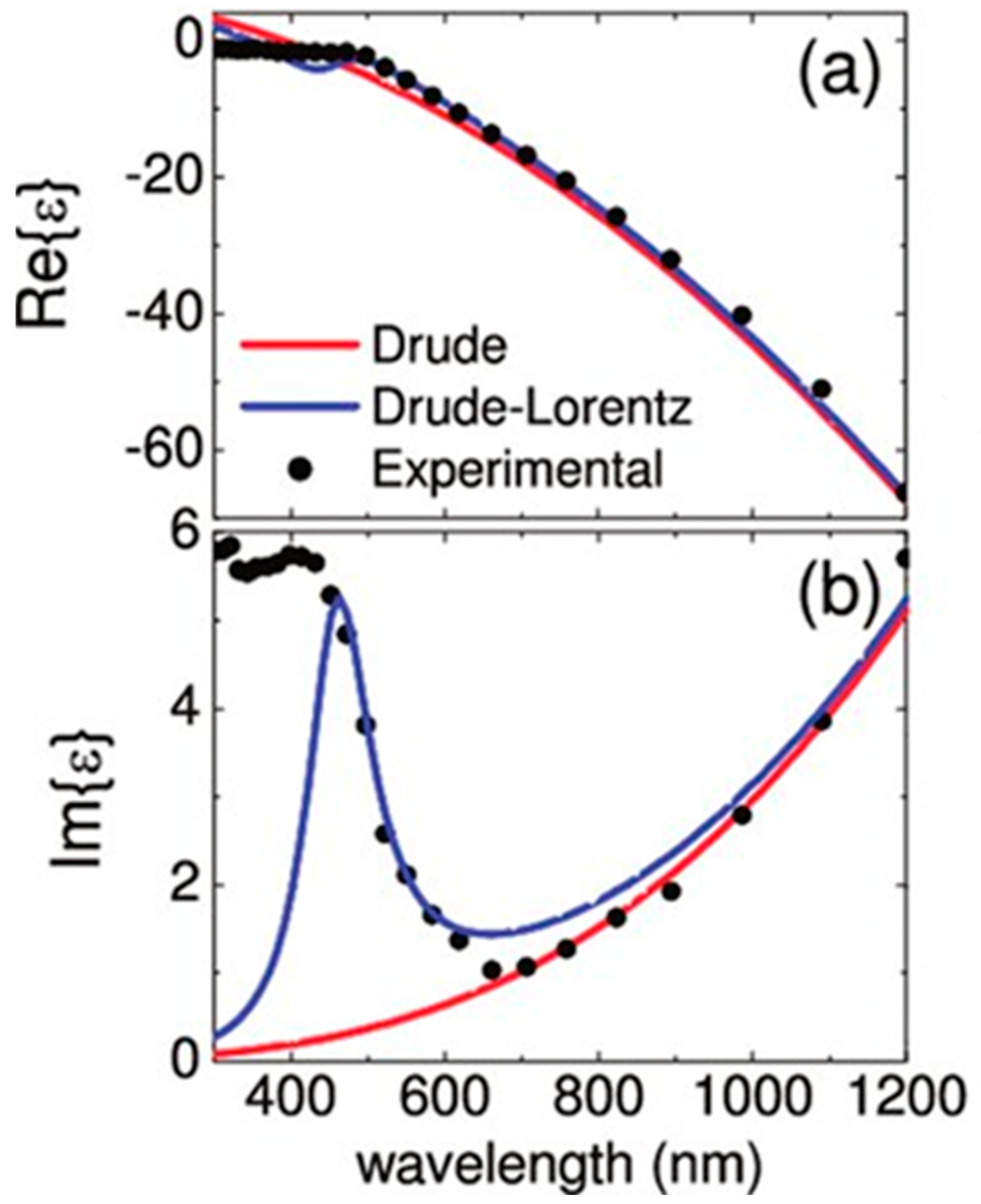
Figure 2.
Coupled excitation involving EM fields (curves) and an electron surface charge density wave (+ and −) forming a propagating SPP along a metal-dielectric interface.
Figure 2.
Coupled excitation involving EM fields (curves) and an electron surface charge density wave (+ and −) forming a propagating SPP along a metal-dielectric interface.

Figure 3.
Dispersion plot of a propagating SPP showing the problem of momentum mismatch between illuminating light (blue line) and the SPP (orange curve). It is necessary to overcome momentum mismatch in order to couple the incident light to the SPP, because the SPP is on the right side of the light line, having higher momentum () than a free space photon () of the same frequency. In order to provide additional momentum, one can use evanescent wave coupling in total internal reflection from a prism, = (red line).

Figure 4.
Sketch of 1D normal electric field profiles (real part), Re{Ez(z)}, for (a) the single-interface SPP, and (b) two coupled SPP modes on a thin metal film, ab and sb. The propagation direction may be taken along the y axis.
Figure 4.
Sketch of 1D normal electric field profiles (real part), Re{Ez(z)}, for (a) the single-interface SPP, and (b) two coupled SPP modes on a thin metal film, ab and sb. The propagation direction may be taken along the y axis.

Figure 5.
Metal stripe of thickness t and width w bound by dielectrics. The substrate and cladding are generally not the same, but is required for LRSPP propagation. The propagation direction is along the y axis.
Figure 5.
Metal stripe of thickness t and width w bound by dielectrics. The substrate and cladding are generally not the same, but is required for LRSPP propagation. The propagation direction is along the y axis.
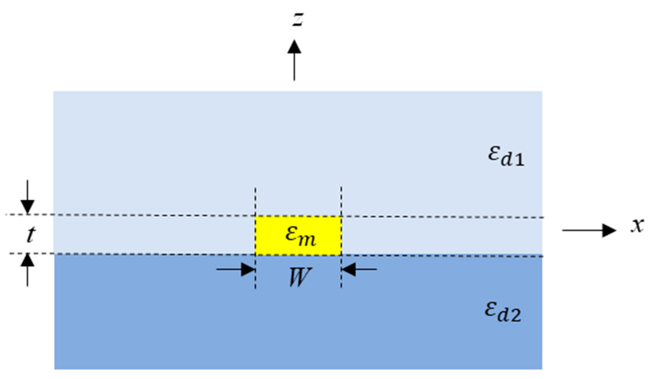
Figure 6.
Excitation of SPPs using (a) Otto and (b) Kretschmann–Raether configurations.

Figure 7.
Prism coupling technique for exciting LRSPPs; εp is the relative permittivity of the prism (=np2) and is the relative permittivity of the dielectrics bounding the metal, the outer one being the sensing solution.
Figure 7.
Prism coupling technique for exciting LRSPPs; εp is the relative permittivity of the prism (=np2) and is the relative permittivity of the dielectrics bounding the metal, the outer one being the sensing solution.

Figure 8.
Geometry of a grating coupler for SPPs as a step-in-height metal pattern.

Figure 9.
(a) Au stripe on a truncated 1DPC covered by Cytop, supporting Bloch LRSPPs. (b) Profiles of the squared magnitude of the perpendicular electric field of the LRSPP on a Au stripe buried in Cytop (left panels), and of the Bloch LRSPP on a Au stripe on a truncated 1DPC covered in Cytop (right panels). Reprinted with permission from [43]. Copyright 2017 American Chemical Society.
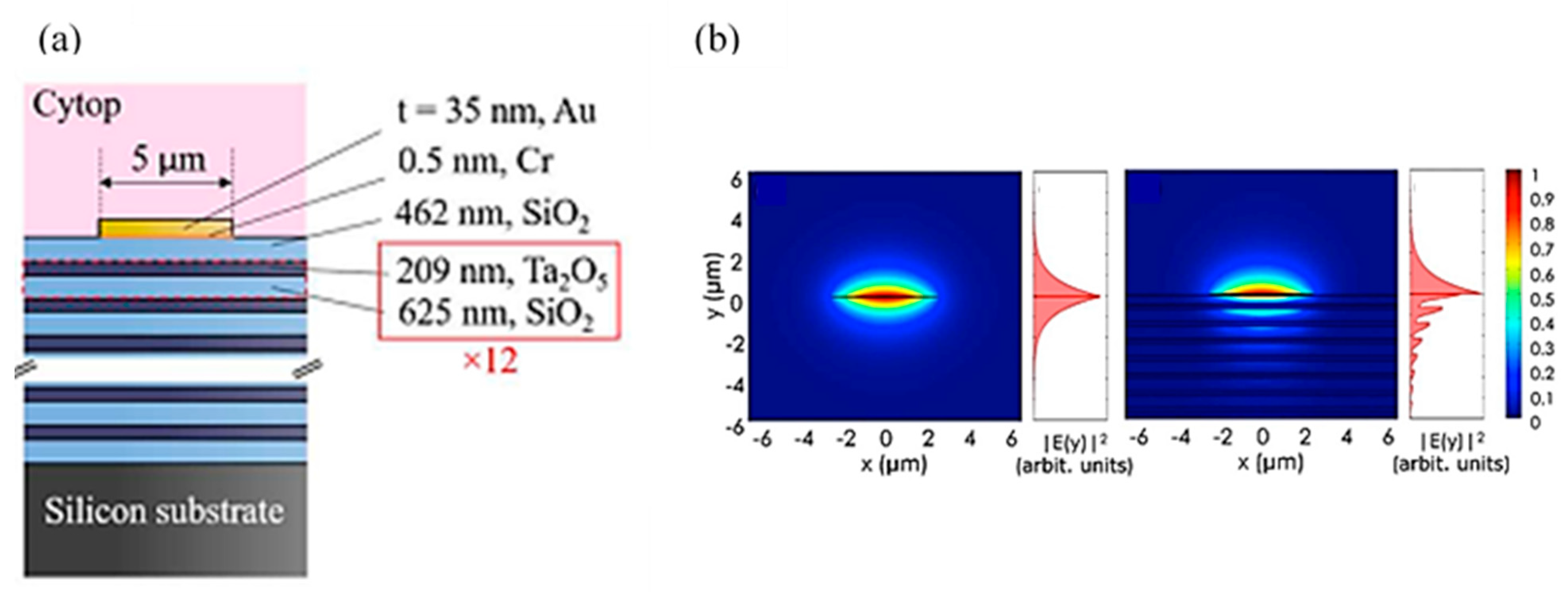
Figure 10.
Isometric sketch of a metal stripe waveguide with a grating coupler on a 1DPC, illustrating an excitation arrangement involving a polarisation-maintaining single-mode fibre. Reprinted with permission from [43]. Copyright 2017 American Chemical Society.
Figure 10.
Isometric sketch of a metal stripe waveguide with a grating coupler on a 1DPC, illustrating an excitation arrangement involving a polarisation-maintaining single-mode fibre. Reprinted with permission from [43]. Copyright 2017 American Chemical Society.

Figure 11.
Schematic illustrating the SPR immunoassay technique. Adapted with permission from [69]. Copyright 2007 Elsevier.
Figure 11.
Schematic illustrating the SPR immunoassay technique. Adapted with permission from [69]. Copyright 2007 Elsevier.
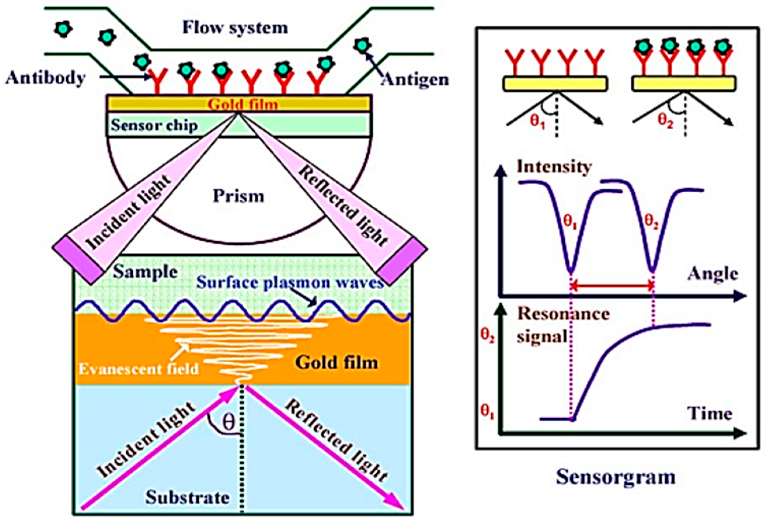
Figure 12.
Schematic voltammograms. To report CV data, US and IUPAC conventions are commonly used. The data reported in the two conventions appear rotated by . Reprinted with permission from [97]. Copyright 2018 American Chemical Society.
Figure 12.
Schematic voltammograms. To report CV data, US and IUPAC conventions are commonly used. The data reported in the two conventions appear rotated by . Reprinted with permission from [97]. Copyright 2018 American Chemical Society.
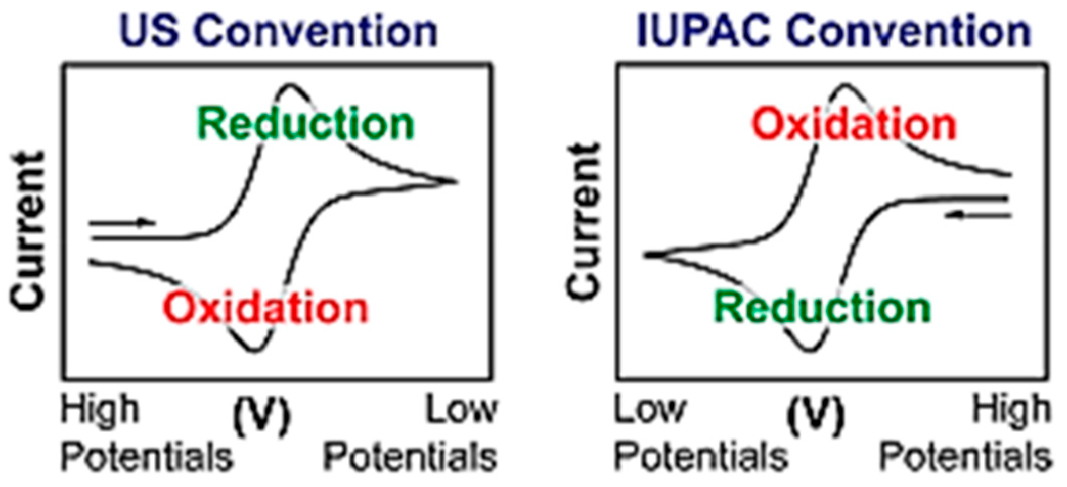
Figure 13.
(a) Applied potential vs. time in a cyclic voltammetry experiment, with the starting, switching, and ending potentials identified. (b) Voltammogram of a reversible reaction (IUPAC convention). Reprinted with permission from [97]. Copyright 2018 American Chemical Society.
Figure 13.
(a) Applied potential vs. time in a cyclic voltammetry experiment, with the starting, switching, and ending potentials identified. (b) Voltammogram of a reversible reaction (IUPAC convention). Reprinted with permission from [97]. Copyright 2018 American Chemical Society.
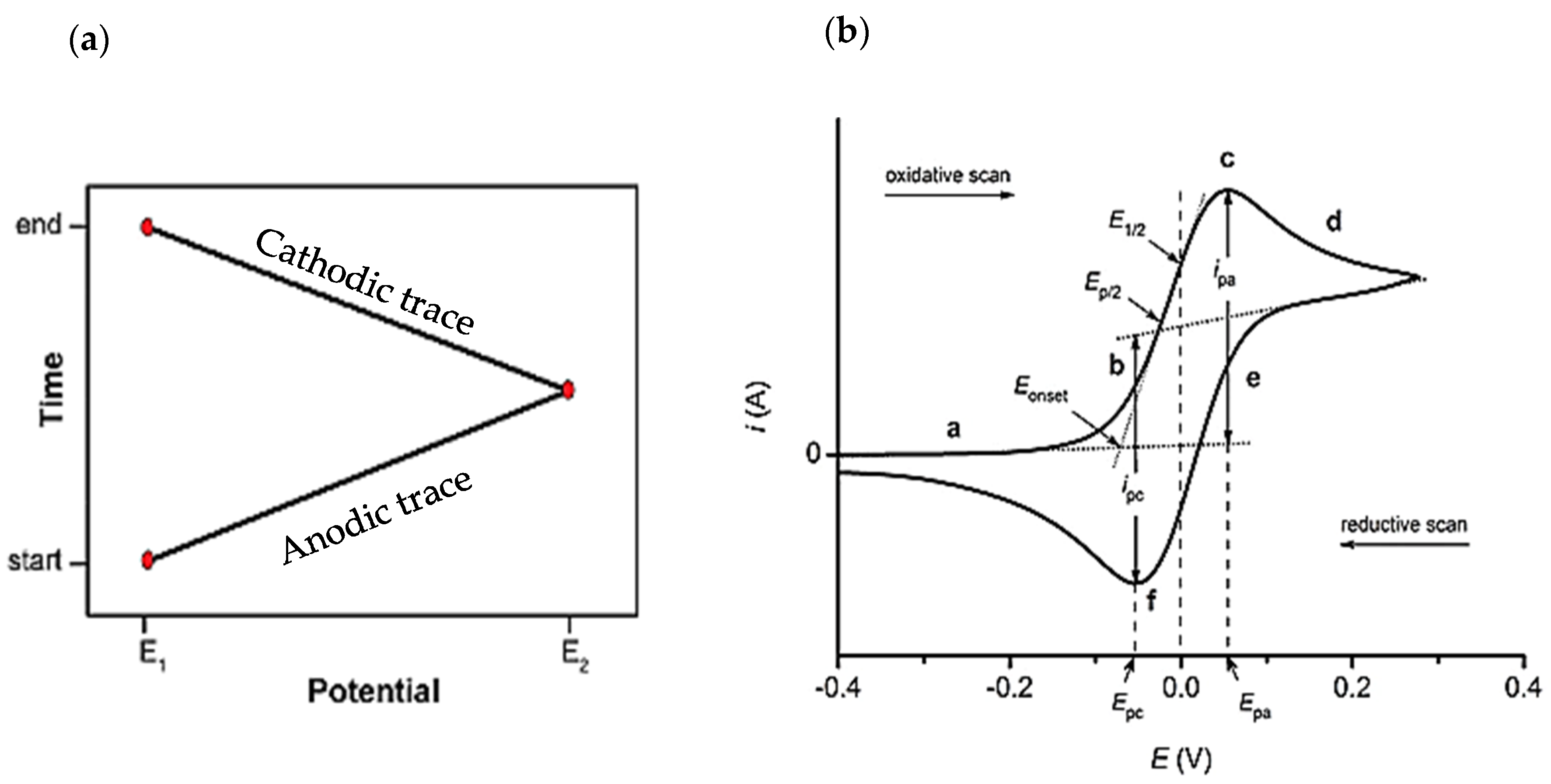
Figure 14.
(A) Sketch of the SPR setup. (B) SPR images in 11.78 mM dissolved in phosphate buffer (0.5 M pH 7), at potentials of −0.1 and −0.3 V (vs. Ag/AgCl), and their difference. The Au (bare) and SAM-coated regions used for data extraction and processing are highlighted by yellow squares. Reprinted with permission from [98]. Copyright 2010 American Chemical Society.
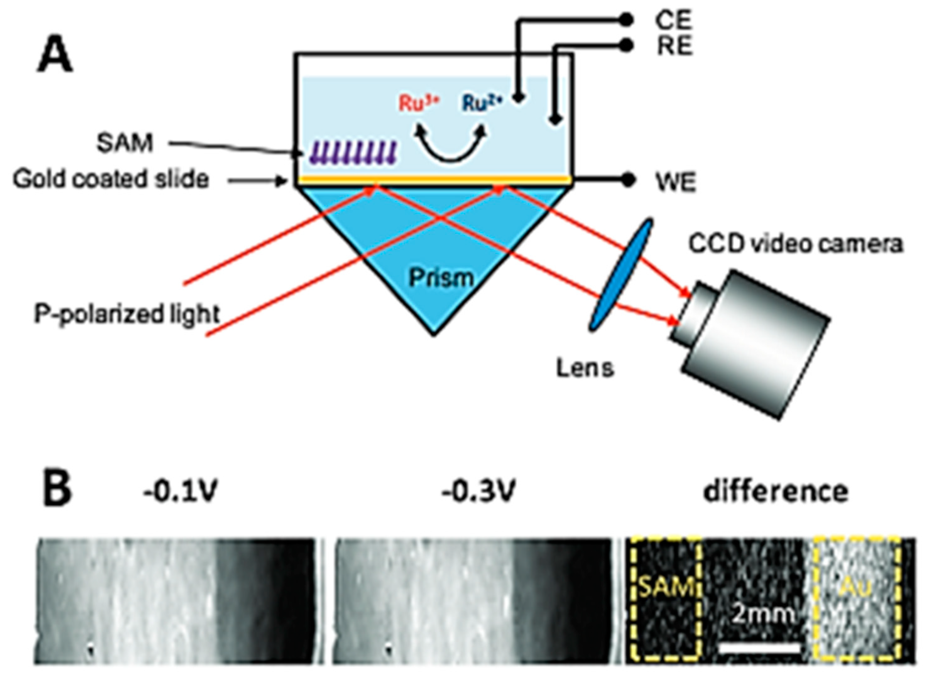
Figure 15.
(A) Measured current voltammograms. (B) Measured SPR voltammograms. (C) SPR voltammograms calculated using Equation (18) and the results of panel (A) as inputs. The electrolyte was 3 mM in phosphate buffer and the electrode/SPR surface was bare gold. Reprinted with permission from [98]. Copyright 2010 American Chemical Society.
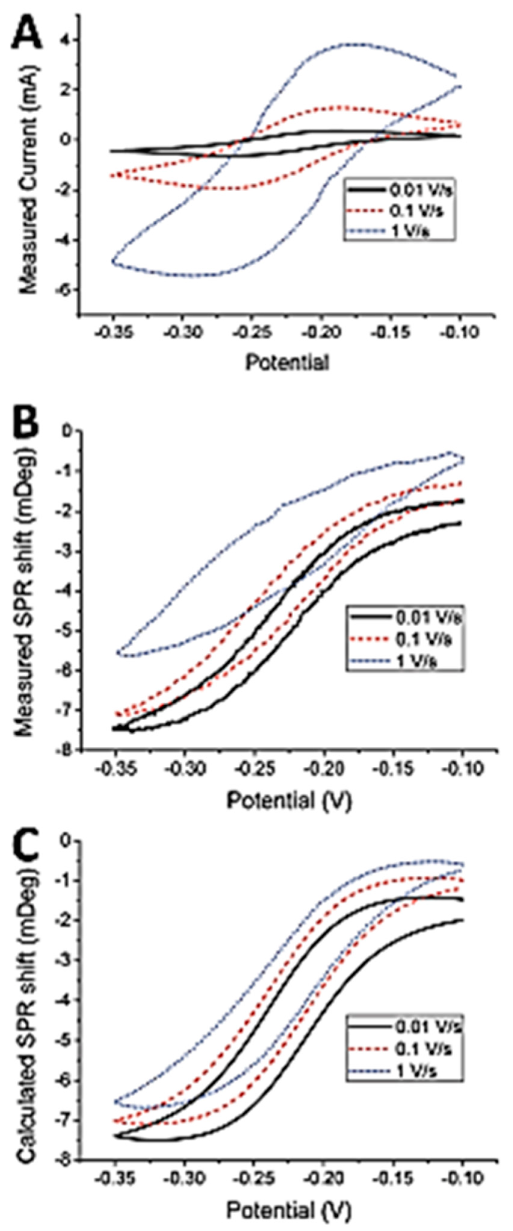
Figure 16.
Shift in SPR peak position and width vs. potential for a silver coated prism in 0.1 M NaF and 0.1 M NaClO4. The shifts are relative to the position and width at −0.76 V [99]. Reprinted with permission from [99]. Copyright 1980 Elsevier.
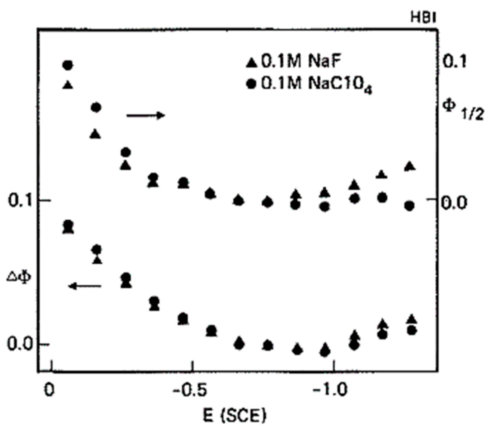
Figure 17.
(Left panel): Top-view sketch of a Au-coated sensing chip with two flow channels connected in a U-shape and the electrodes. The width, height and length of each channel are, respectively, 2.0, 0.5, and 5 mm. The working electrode (WE) is connected to the sensing chip by a contact pin. The counter electrode (CE) and reference electrode (RE) are in the flow channel at the locations indicated. The solution is injected into the cell via channel 1 and emerges from channel 2. Position 1 is on the WE, and positions 2 and 3 are downstream. It takes 0.1 and 5 s for the solution to flow from position 1 to positions 2 and 3, for a flow rate of 100 μL/min. (Right panel): Characterization of BQ•− by CV-SPR at positions 1, 2, and 3. (a) Current of the HQ–BQ and of the solvent (0.1 M Bu4NPF6 in acetonitrile), and of HQ–BQ over a non-reactive potential window. (b) SPR signal of the HQ–BQ and of the solvent (0.1 M Bu4NPF6 in acetonitrile), and of HQ–BQ in a non-reactive potential window at position 1. (c) SPR signal of the HQ–BQ at position 2. (d) SPR signal of the HQ–BQ at position 3. Flow rate: 100 μL/min. Potential scan rate: 0.1 V/s. Reprinted with permission from [100]. Copyright 2010 Elsevier.
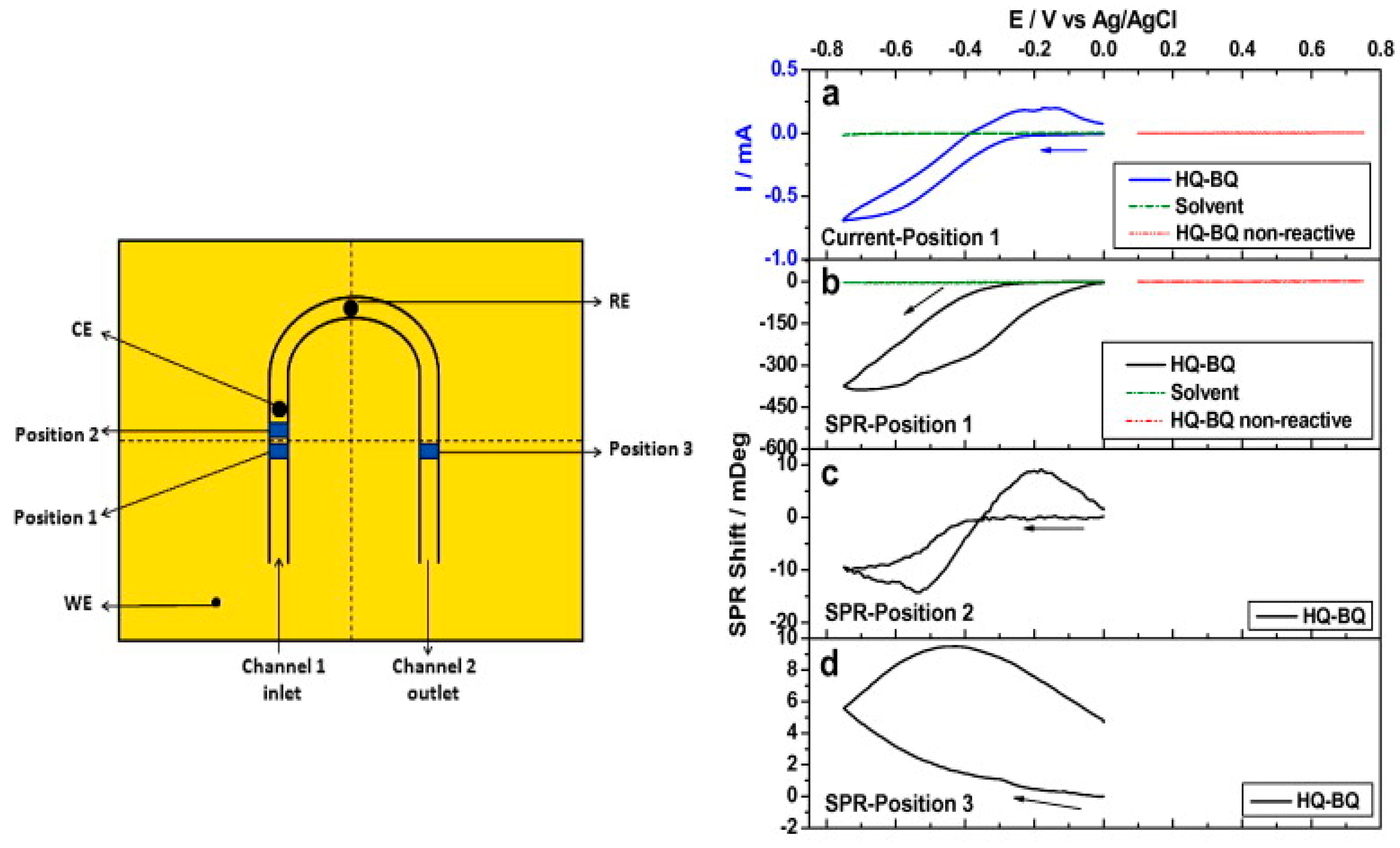
Figure 18.
Plasmonic metal/n-type semiconductor photoanode working electrode for redox of water. (a) Energy band diagram of a Au/ photoanode. Absorption of visible light in Au generates energetic electron-hole pairs therein. Hot electrons emitted from Au into enable water reduction on the counter electrode (acting as cathode), and hot holes in Au are extracted by a Co-based oxygen evolution catalyst (Co-OEC) on Au to enable water oxidation. Current vs. time for Au/ (b) with Co-OEC, and (c) without Co-OEC. Reprinted with permission from [106]. Copyright 2012 American Chemical Society.
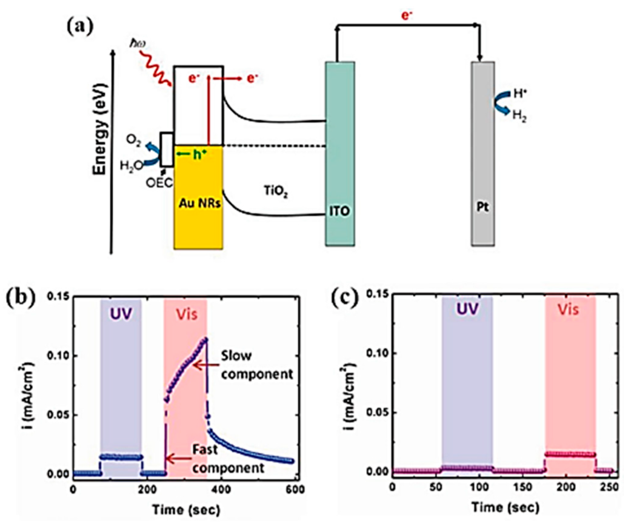
Figure 19.
Plasmonic photocathode comprised of a metal on a p-type semiconductor and reduction of CO2. (a) Energy band diagram of a Au/p-GaN photocathode, illustrating the conduction band edge , the valence band edge , the Fermi level energy , the bandgap energy and the Schottky barrier potential . Plasmon absorption creates hot electrons (red) and hot holes (blue) above and below EF, respectively. Hot holes with energies larger than can overcome the Schottky barrier to populate available valence band levels in p-GaN. (b) Linear sweep voltammetry of Au/p-GaN (red) and bare p-GaN (blue) photocathodes. Reprinted with permission from [107]. Copyright 2018 American Chemical Society.
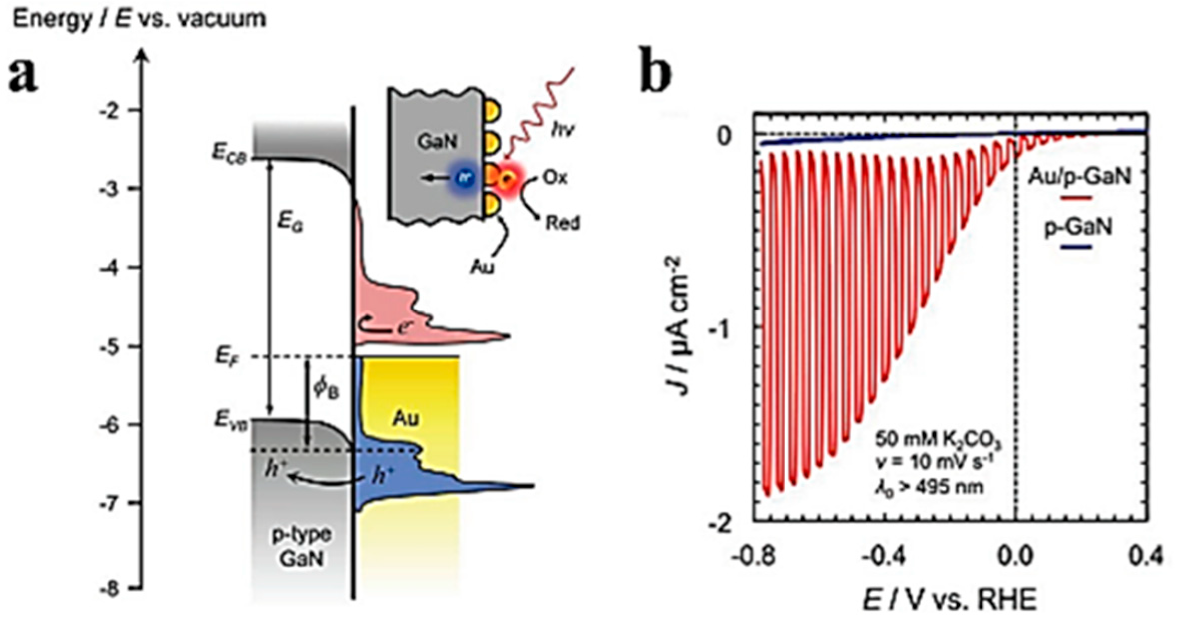
Figure 20.
(Top left): velocity and (top right): temperature distributions of the electrolyte near a glassy carbon electrode (1.5 mm radius) embedded in an insulating sheath (white rectangle) in an electrochemical cell, obtained via FEM modelling of heat transfer including conduction and convection in electrolyte for 10 heat input at the surface. The magnitude of the velocity and the temperature are shown on their respective color bars 10 s after the onset of heating. The (bottom panels) give the corresponding vertical distributions of the z-component of the velocity, vz, and of the temperature. The red curve on the bottom right panel gives the temperature profile computed using a simple 1D model neglecting convection. Reprinted with permission from [113]. Copyright 2019 American Chemical Society.
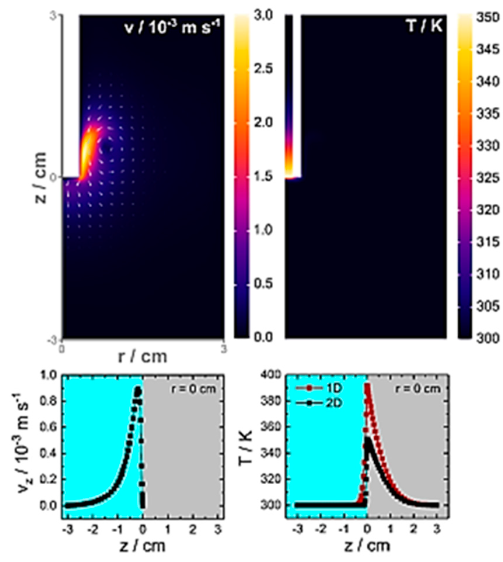
Figure 21.
Schematic in top view of the sensing chip. The thickness of the Au working electrode (WE, yellow) and of the Pt counter electrode (CE, gray) is t = 35 nm and their dimensions are: l1 = 29 μm, l2 = 2600 μm, l3 = 1850 μm, l4 = 250 μm, lchip = 3000 μm, wc = 100 μm, w = 5 μm, ls = 40 μm. The Bloch LRSPPs propagating along the WE are excited using an optical beam normally incident on an input grating coupler. The output grating coupler produces a normally emerging output optical beam that can be monitored. Reprinted with permission from [119]. Copyright 2022 American Chemical Society.
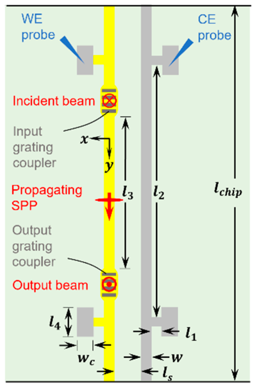
Figure 22.
Cyclic voltammetry under optical illumination. (A) CV curves obtained at a scan rate of 100 mV/s, on a Au WE in 0.5 mM K3[Fe(CN)6] + 100 mM KNO3 electrolyte, as the optical power at λ0 = 1350 nm increases (legend—the output power was monitored). The incident optical power ranged from 0 to 6.3 mW. The black dots plot the reference CV curve (laser off). (B) Redox current peaks, and (C) potentials vs. output optical power, from CV curves measured at λ0 = 1330, 1350 and 1370 nm. The blue dashed lines on Parts (B,C) plot the linear thermal trends measured independently, ruling out thermal effects. Reprinted with permission from [118]. Copyright 2022 The Authors, licensed under a Creative Commons Attribution (CC BY) license.

Disclaimer/Publisher’s Note: The statements, opinions and data contained in all publications are solely those of the individual author(s) and contributor(s) and not of MDPI and/or the editor(s). MDPI and/or the editor(s) disclaim responsibility for any injury to people or property resulting from any ideas, methods, instructions or products referred to in the content. |
© 2023 by the authors. Licensee MDPI, Basel, Switzerland. This article is an open access article distributed under the terms and conditions of the Creative Commons Attribution (CC BY) license (https://creativecommons.org/licenses/by/4.0/).
Share and Cite
MDPI and ACS Style
Hirbodvash, Z.; Berini, P. Surface Plasmon Electrochemistry: Tutorial and Review. Chemosensors 2023, 11, 196. https://doi.org/10.3390/chemosensors11030196
AMA Style
Hirbodvash Z, Berini P. Surface Plasmon Electrochemistry: Tutorial and Review. Chemosensors. 2023; 11(3):196. https://doi.org/10.3390/chemosensors11030196
Chicago/Turabian StyleHirbodvash, Zohreh, and Pierre Berini. 2023. "Surface Plasmon Electrochemistry: Tutorial and Review" Chemosensors 11, no. 3: 196. https://doi.org/10.3390/chemosensors11030196
Note that from the first issue of 2016, this journal uses article numbers instead of page numbers. See further details here.