Article

Wavelength-Stable Metal Grating Distributed Feedback Quantum Cascade Laser Emitting at λ ~ 7.2 μm

1
Key Laboratory of Optoelectronic Materials Chemistry and Physics, Fujian Institute of Research on the Structure of Matter, Chinese Academy of Sciences, Fuzhou 350002, China
2
University of Chinese Academy of Sciences, Beijing 100049, China
3
Key Laboratory of Semiconductor Materials Science, Institute of Semiconductors, Chinese Academy of Sciences, Beijing 100083, China
4
School of Physics, University of Electronic Science and Technology of China, Chengdu 611731, China
*
Author to whom correspondence should be addressed.
Chemosensors 2024, 12(1), 2; https://doi.org/10.3390/chemosensors12010002
Submission received: 24 October 2023 / Revised: 20 December 2023 / Accepted: 22 December 2023 / Published: 26 December 2023
(This article belongs to the Special Issue Advances in Optoelectronic Materials-Based Sensors and Devices)

Abstract

:
In this research, we demonstrate a wavelength-stable continuous wave (CW) distributed feedback (DFB) quantum cascade laser (QCL) emitting at 7.2 μm using a surface metal grating approach without epitaxial regrowth. The deep metal grating provides an appropriate DFB coupling coefficient and enhanced thermal extraction, resulting in improved lasing performance and the realization of impressive wavelength stability. Quantitatively, the temperature tuning coefficient of the single-mode emission is only 0.54 nm/°C from 20 °C to 70 °C, and the current tuning coefficient of the single-mode emission is 3.2 nm/A from 1.0 A to 1.6 A. A DFB-QCL with a 2 mm cavity length exhibits a low threshold current of 0.6 A and a power of 1.1 W with a slope efficiency of 1 W/A in the CW mode at 300 K. A single-mode operation with a side mode suppression ratio of 33 dB and a single-lobed far-field without beam steering is obtained in the working temperature range of 20–70 °C The improved wavelength stability using a deep surface metal grating approach promises simplified fabrication, which is meaningful for the commercial applications of QCLs.

1. Introduction

Mid-infrared optoelectronic devices, such as lasers and detectors, are in high demand owing to applications involving the imaging and remote sensing of trace pollutants and industrial chemicals, where lasers with wavelengths in the range of 3 to 12 μm are crucial [1,2,3,4,5]. A wavelength-tunable and stable quantum cascade laser (QCL) stands out as the preferred choice. The QCL, a semiconductor laser based on intersubband transitions, provides a devisable lasing wavelength across the entire mid-infrared range [6,7]. Moreover, the QCL exhibits the unique advantages of compact, high-power, and flexible emission wavelengths [8,9,10]. Considering several important gases, including CH4, N2H4, and SO2, which have characteristic absorption peaks at around 7 μm, QCLs operating at around 7 μm with single-mode, high-performance, ideal beam coherence, as well as superior wavelength stability, have become imperative demands [11,12,13,14].
The distributed feedback (DFB) laser is regarded as an effective technology for achieving single-mode lasing and ideal beam quality with a mature fabrication process [11,15]. So far, DFB QCLs with buried grating have demonstrated impressive lasing properties in the mid-infrared spectral range [16,17]. For instance, watt-level output power is achieved in continuous-wave (CW) mode at room temperature within the wavelength range of 4.6–7.0 μm. The highest operation temperature reaches over 100 °C, and the side-mode suppression ratio (SMSR) exceeds 30 dB [18,19,20,21]. Compared with the buried gratings utilized in DFB laser devices, the surface metal gratings offer the advantages of avoiding waveguide regrowth and simplifying the manufacturing process [22,23,24,25]. Due to the benefits of a simple fabrication process and low facility requirements [26], various surface metal grating DFB lasers have been explored in recent years [27,28,29,30,31]. Since the investigation of the surface metal grating DFB QCL in 2006 [22], the performance of DFB QCL devices with metal gratings has shown continuous improvement [32]. A record high output power single-mode QCL with a 30 dB SMSR emitting at λ ~ 4.8 μm has been realized [23,24]. The progress in metal grating DFB QCL shows the potential of approaching reliable single-mode mid-infrared lasing with a brief process. However, metal grating DFB QCLs have a weakness: the unstable wavelength. Specifically, due to the thick cladding waveguide of mid-infrared QCLs, the surface metal grating is positioned far from the active region, resulting in a weak coupling coefficient (κ) for metal grating QCLs. Consequently, general metal grating DFB QCLs require a long cavity length to achieve sufficient coupling strength κL [24,33]. However, the long cavity length of the DFB laser not only induces spectral distortion, such as photon hole burning, but also enhances thermal accumulation in the laser cavity, leading to diminished performance and a significant wavelength shift [32,34]. At present, for surface metal grating DFB QCLs, the reported temperature tuning coefficient of single-mode emissions could reach 0.9 nm/°C, and the current tuning coefficient of single-mode emission is 11.8 nm/A in CW mode [24,25]. Nevertheless, in the practical operation of mid-infrared sensing, avoiding wavelength shifts is crucial. This is because a wavelength shift can cause a mismatch between the accurate lasing wavelength and the fingerprint-like absorption peaks of target gases, leading to distorted sensing results [35]. Consequently, the reported metal grating DFB QCLs fail to meet the demands of commercial trace gas sensing. Hence, improving the wavelength stability of metal grating DFB QCLs is imperative.
In this work, deep surface grating with thick capping metal is put forward to increase the coupling coefficient and improve thermal extraction. The grating depth is etched to approximately 500 nm, and the innovative fabrication process of the deep surface grating achieves a coupling strength of 2.6 with a 2 mm device cavity length. Herein, we present a high-performance metal grating DFB QCL emitting at λ ~ 7.2 μm at room temperature in CW mode. The watt-level output power device shows improved single-mode stability within the temperature range of 20–70 °C and a current range of 1.0–1.8 A. The realizations of wavelength-stable metal grating DFB QCL with outstanding lasing properties open up new possibilities for mid-infrared lasers.

2. Material Growth and Device Fabrication

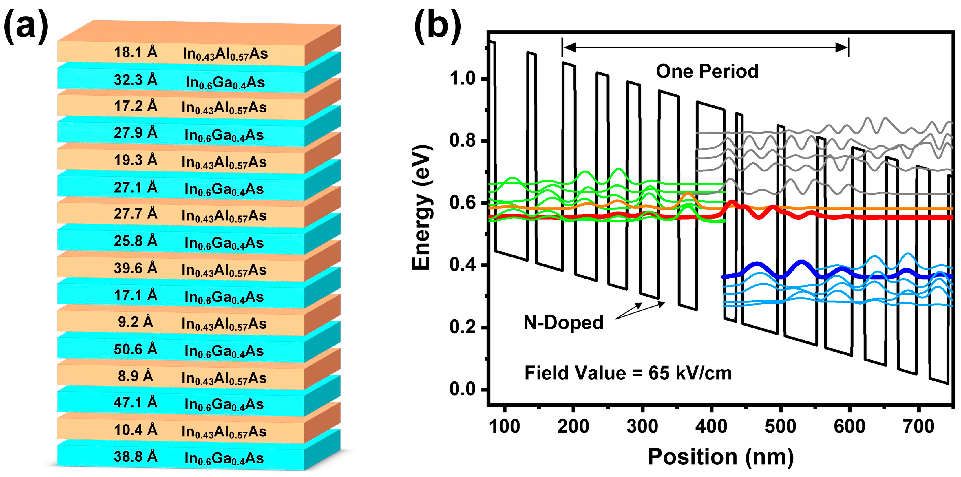
2.1. Material Epitaxy of QCL

The QCL wafer utilized in this work is grown on an n-InP (Si-doped, 1 × 1017 cm−3) substrate, with the active region, serving as the core of the whole laser structure, sandwiched between two n-doping InP cladding layers. The active structure follows a bound-to-continuum design, comprising 50 repetitions of periodic multi-epitaxial layer groups grown by molecular beam epitaxy (MBE) with strain-balanced In0.43Al0.57As/In0.6Ga0.4As material compositions (see Figure 1a). The layer sequence for one period, in angstroms, starting from one In0.43Al0.57As barrier, is 18.1/32.3/17.2/27.9/19.3/27.1/27.7/25.8/39.6/17.1/9.2/50.6/8.9/47.1/10.4/38.8, where the In0.43Al0.57As barrier layers are in bold, In0.6Ga0.4As well layers are in regular font, and two n-doped layers (1.5 × 1017 cm−3) are underlined. Based on this active region structure design, the calculated wavefunctions of relevant energy levels in the conduction band are plotted in Figure 1b. The QCL operating mechanism is based on an optical transition design, where the photon is generated from the carrier transition between the upper energy level (red) and the lower energy level (blue, and Cambridge blue). According to the simulation result, the transition energy is calculated as 178 meV, corresponding to a lasing wavelength of 7.2 μm. During the MBE growth of the active region, optimized growth parameters were employed. InAlAs tend to grow better at high substrate temperatures (510–535 °C) and a low V/III ratio, while InGaAs grow better at low substrate temperatures (480–515 °C) and a high V/III ratio. A compromise was reached by using the same substrate temperature and arsenic overpressure for both materials. Thus, the substrate temperature of 510 °C and the V/III ratio of 15–19 in growth were selected. The growth rate used was approximately 0.7 μm/h and 0.98 μm/h for In0.6Ga0.4As and In0.43Al0.57As, respectively. The temperature stability of group III effusion cells should be calibrated better than 0.2 °C. The group III flux stability was adjusted to better than 1.5%. Due to the sensitivity of the InGaAs layer to the substrate temperature, the operation stability of the substrate heater at the growth temperature was confirmed to be better than 0.3 °C.
The growth of thick InP performed run to run every day using solid source MBE with a valved cracking phosphorus effusion cell will lead to the inevitable residual of white phosphorus in the growth chamber. Because of the limited cracking efficiency of P4 to P2, the unintentional release of P4 is unavoidable. The naturally enhanced vapor pressure of white phosphorus may introduce potential “pollution” during the growth of the InAlAs/InGaAs active region. To mitigate this issue, the InP cladding layers were grown using low-pressure (100 mbar) metal-organic chemical vapor deposition (MOCVD). The precursors were trimethyl indium and purified phosphine. A growth temperature of 600–650 °C and a growth rate of 0.3–0.8 nm/s were used. The lower cladding consists of a 4.3 μm-thick n-InP layer [graded Si doping, (3 − 0.3) × 1017 cm−3)]. The upper cladding is composed of a 4 μm-thick n-InP layer [graded Si doping, (0.3 − 3) × 1017 cm−3)] and a 1 μm-thick n+-InGaAs capping layer (Si doping, 5 × 1018 cm−3).

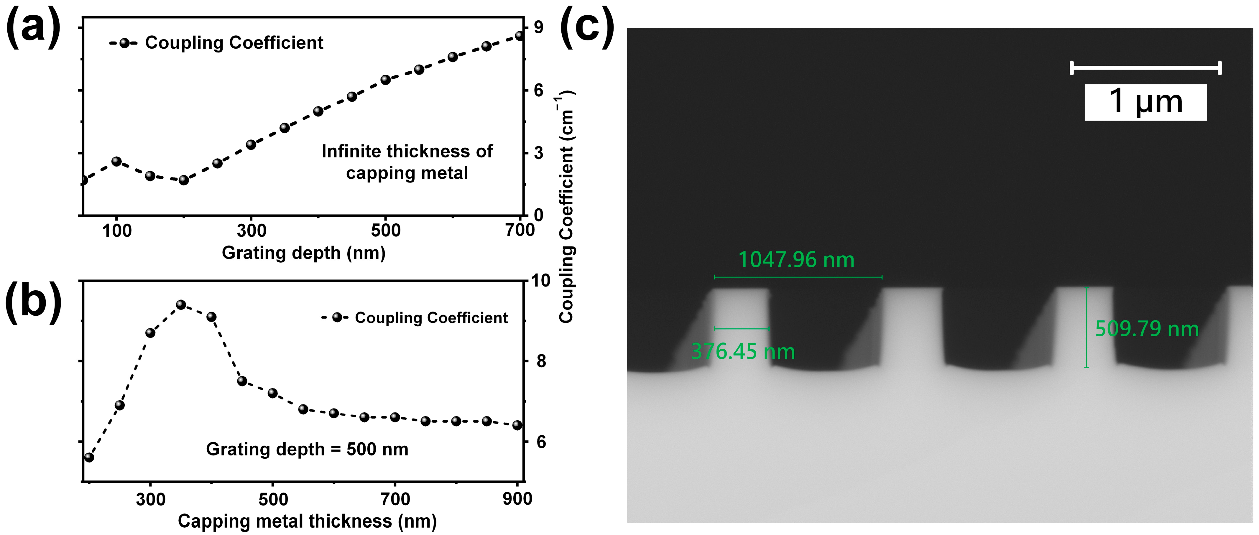
2.2. Design and Fabrication of Surface Metal Grating

In this work, a standard periodic distributed feedback (DFB) type with anti-reflection (AR) coating deposited on the front facet was employed to achieve single-mode lasing. Due to the need for a systematic grating simulation to obtain an optimal optical field distribution and a suitable coupling coefficient value, a surface–plasmon coupling mechanism-based simulation was explored for the grating structure design. The preliminary fabrication process (holographic exposure and inductively coupled plasma dry etching) yielded an ideal grating shape with a 35% duty cycle and a 1050 nm period width. These parameters were retained in the simulation process, with attention focused on enhancing the coupling coefficient by adjusting the grating depth and capping the metal thickness. Under the condition of infinite capping metal thickness, the relationship between the coupling coefficient and grating depth is displayed in Figure 2a. With the rise of grating depth, the coupling coefficient steadily increases when grating is deeper than 200 nm. This shows that increasing the grating depth is an effective method to enhance the coupling coefficient. Therefore, a grating depth of 500 nm was determined, as it was capable of providing a high coupling coefficient. Next, the influence of the capping metal thickness was considered, and the simulated curve of the coupling coefficient value κ versus capping metal thickness is presented in Figure 2b. The coupling coefficient κ reaches its peak when the capping metal thickness is increased to 350 nm, and then decreases with further thickness increase. Finally, the coupling coefficient κ gradually stabilizes around 6.5 cm−1 once the metal thickness exceeds 550 nm. Given that the capping metal used in this work is deposited by micron-order gold (Aurum, Au) with a metal thickness exceeding 550 nm, the expected value of coupling coefficient κ in this research is 6.5 cm−1. Meanwhile, as the cavity length (L) of the laser devices is cleaved to 2 mm, and the back facet of the devices is coated with high-reflectivity (HR) coating, the simulated value of the designed coupling strength κL is calculated as 2.6.
Afterward, holographic lithography combined with standard inductively coupled plasma (ICP) dry etching was employed to produce the DFB grating on the highly doped capping InGaAs layer situated on top of the wafer. ICP dry etching of high-depth gratings poses challenges due to the instability of the gas etching rate with increasing depth, making it difficult to guarantee the morphology of the deep grating. To achieve deep grating with ideal morphology, the fabrication processes of holographic lithography and ICP dry etching were optimized. In holographic lithography, a high-precision and highly photosensitive coupling photoresist (S1805) was adopted to achieve the flatness of the SiO2 hard mask, reducing the serrated morphology of the grating sidewall after dry etching of InGaAs. During the ICP dry etching process, the etching temperature was elevated to 240 °C; the aim was to use high-temperature dry etching to prevent the accumulation of etching products on the surface of the grating. Simultaneously, optimized menus and parameters were applied in the ICP etching process, with the etching gas adopting the chlorine gas to argon gas ratio of 1.5:40, and the power settings for the ICP RF and Table RF corresponding to 300 W and 100 W, respectively. The optimized ICP process aims to ensure the etched grating sidewall is vertical and the bottom is flat.
The actual morphology of the DFB grating can be observed through scanning electron microscope (SEM) pictures, as shown in Figure 2c. The period width and etching depth of the grating are measured at 1047.97 nm and 509.79 nm, respectively, resulting in a calculated grating duty cycle of approximately 36%. The actual shape of the DFB grating after processing closely aligns with the expected structure design, featuring a 1050 nm period width, 500 nm grating depth, and 35% duty cycle. Therefore, the actual coupling strength κL is expected to be close to the simulated value of 2.6, indicating a slightly over-coupled state. As a strong coupling strength contributes to confining the laser to the center of devices and facilitates the production of single-mode operation, the structure of the grating and the design of the corresponding coupling strength are anticipated to achieve a high-performance single-mode mid-infrared lasing operation.

2.3. Fabrication of QCL Devices

After finishing the fabrication of metal grating on the surface, the wafer was transformed into metal grating DFB QCL devices with a double-channel ridge waveguide. The double-channel ridge waveguide, with a 10 μm core active region width, was created through ICP dry etching. Subsequently, wet etching was employed to refine the roughness induced by the uneven dry etching hard mask formed by the DFB grating on the top of the waveguide, resulting in a stripe-like rough sidewall. Following the deposition of the standard insulation layer (SiO2) and window opening, 30 nm Ti and 120 nm Au were deposited and annealed to establish ohmic contact metallization. A micron-order thick Au metal layer was then plated on the surface to fill and flatten the DFB grating and channel. The fabricated sample was cleaved into independent devices with a 2 mm cavity length and optical coating. The back facet of the devices received a high-reflecting (HR) coating consisting of 165 nm Al2O3/20 nm Ti/50 nm Au/25 nm Ti/120 nm Al2O3, while the front facet was coated with an anti-reflective (AR) coating comprising periodic 135 nm Al2O3/45 nm Ge. The measured reflectivity values for HR and AR coatings are 98.8% and 0.3%, respectively. Finally, the lasers were flip-chip mounted epi-side down on diamond heat sinks with indium solder, and then subsequently bonded to copper heat sinks. The fabrication process of QCL devices in this research adheres to the standard fabrication and packaging procedures for semiconductor optoelectronic devices, ensuring repeatability and verifiability.

3. Results and Discussion

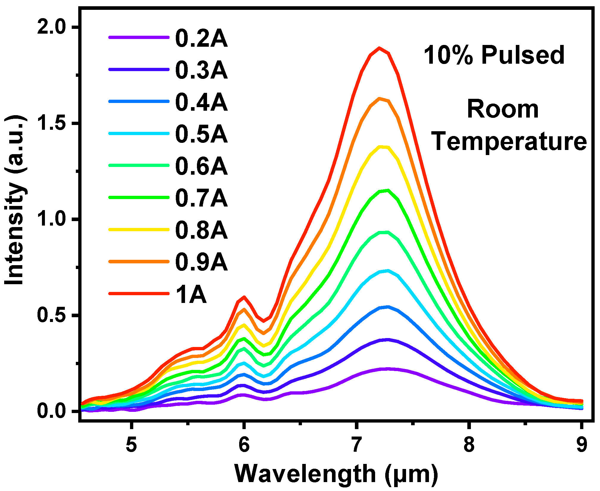
3.1. Electroluminescence Spectra of QCL

In order to acquire the internal energy level information from the epitaxial laser material, the majority of the grown QCL wafer was processed into surface metal grating DFB QCL devices. Additionally, a portion of the sample was fabricated into a Fabry–Perot (FP) laser to obtain electroluminescence (EL) spectra. The spectrum of the 20-μm-wide/3-mm-long FP device was subsequently measured using Fourier-transform infrared (FTIR) and a mercury cadmium telluride (MCT) detector under room temperature, using different current levels in the pulsed injection mode (5 μs pulse width, 20 kHz repetition rate, 10% duty cycle). As shown in Figure 3, with the resolution of 0.5 cm−1 in FTIR rapid scan mode, the EL results of the QCL device were obtained with the progressively pumped current ranging from 0.2 A to 1 A. The main emission peak consistently appeared at around 7.2 μm, which is consistent with the calculated value derived from band structure simulation. A weaker peak at around 6 μm arose from the carrier transmission from a higher parasitic energy level to a low energy level, as indicated by the orange color in the simulation result (Figure 1b). The EL peak exhibited a behavior akin to being “current-pinned,” wherein a fivefold increase in the driving current resulted in minimal change in the peak. Consequently, it is conceivable that the lasing spectrum of the QCL device is also insensitive to changes in the driving current. This characteristic suggests a promising avenue for achieving substantial wavelength stability in these QCL devices.

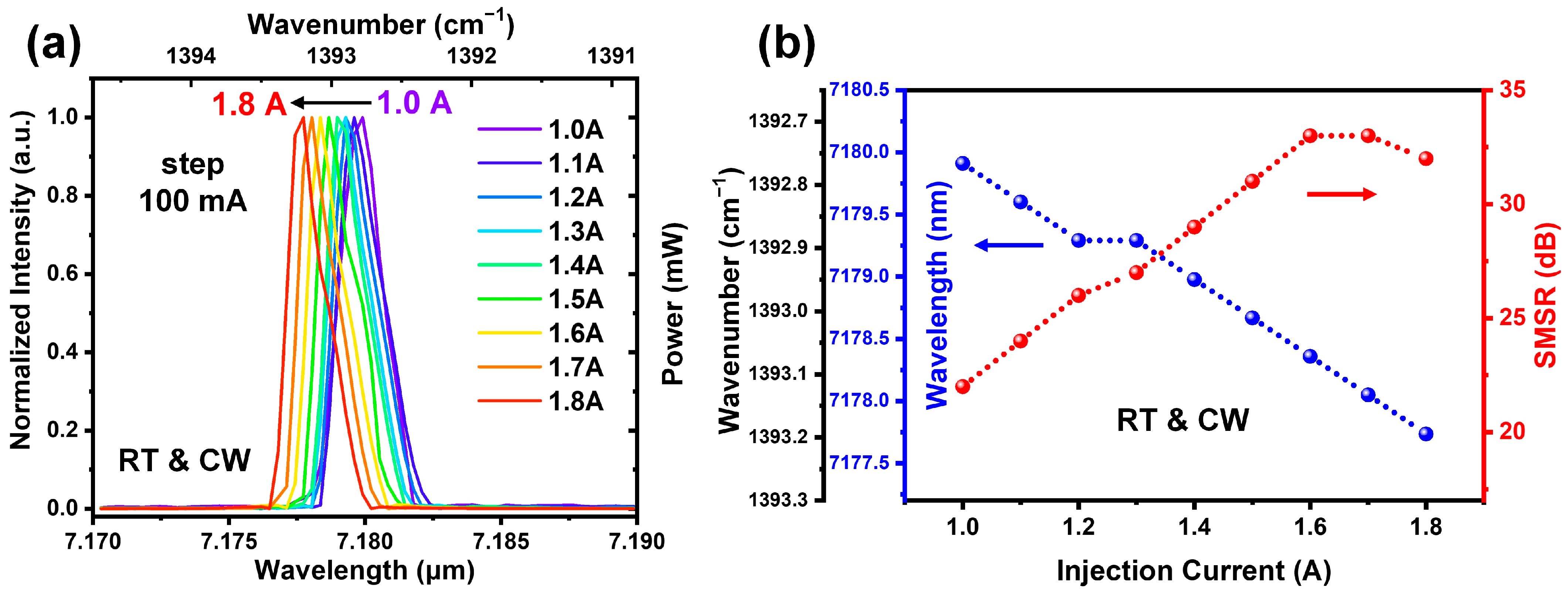
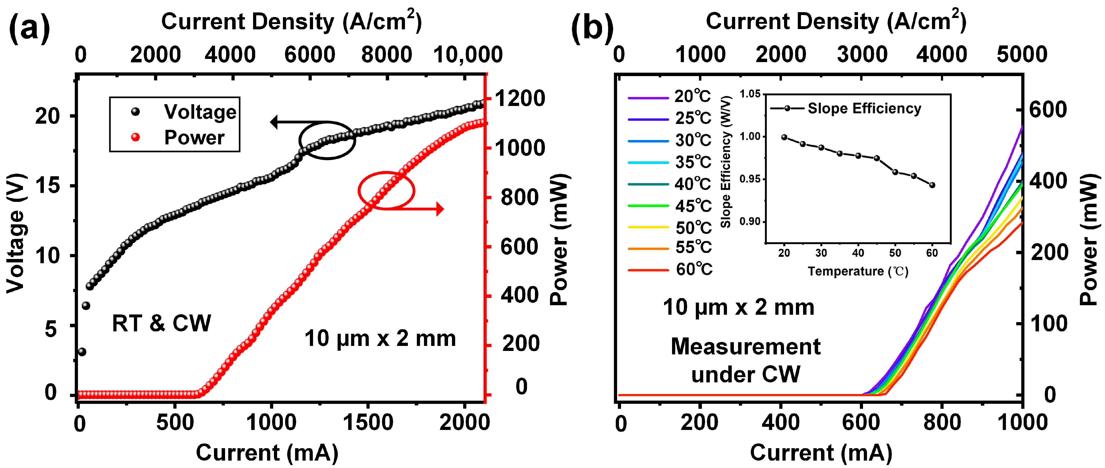
3.2. Lasing Performance of Metal Grating DFB QCL

Upon completing the wafer epitaxy and laser device fabrication, measurements were conducted to comprehensively evaluate the performance of QCL devices featuring a 2 mm cavity length and a 10 µm ridge width. The typical light current–voltage (LIV) results, obtained under room temperature conditions (300 K) with the continuous wave (CW) mode injection current, are presented in Figure 4a. The laser device shows excellent operational characteristics, boasting a 600 mA threshold current and a high slope efficiency of 1 W/A. As the injection current increases, the output power could surpass 1.1 W.
Subsequently, employing a thermoelectric cooler (TEC) for temperature control, the temperature-dependent output power of the QCL was measured across the range of 20 °C to 60 °C, with the results shown in Figure 4b. With the increasing operating temperature, the slope efficiency and threshold current of the laser exhibit slight changes under continuous wave driving, while the threshold current increases marginally from 600 mA to 665 mA, and the calculated slope efficiency decreases to approximately 0.94 W/A from 1 W/A. Thus, the QCL device in this research demonstrates not only an impressive slope efficiency but also remarkable thermal stability of output power.

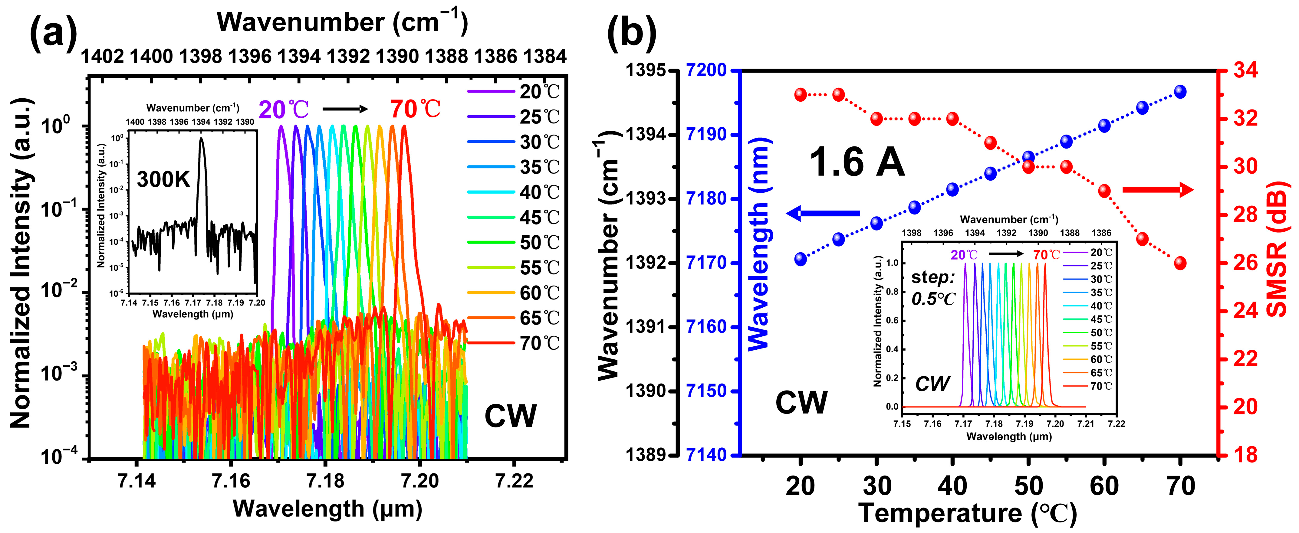
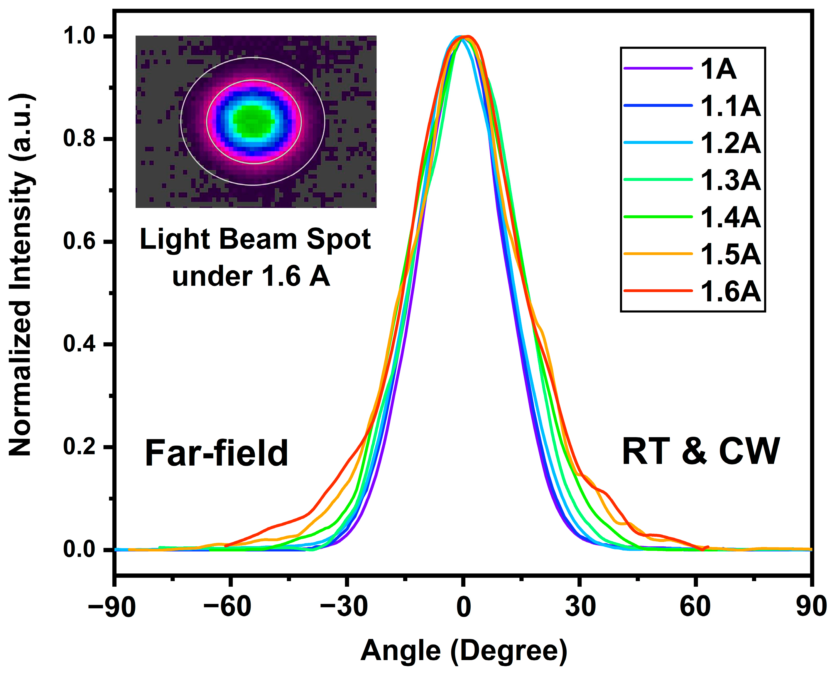
3.3. Wavelength-Stable Metal Grating DFB QCL

As mentioned in the preceding section of this paper, wavelength stability stands as a crucial criterion for DFB laser devices, and the imperative need for the low wavelength shift in DFB QCLs becomes apparent for practical applications. Therefore, the lasing spectrum of the devices was measured by Fourier-transform infrared (FTIR) and a deuterated triglycine sulfate (DGTS) detector, with a resolution of 0.06 cm−1. The wavelength shift was then calculated from the obtained spectrum results.
The spectrum results, representing the variation in injection current, are illustrated in Figure 5a. In this depiction, the 2 mm × 10 μm QCL device is driven by the CW mode current ranging from 1.0 A to 1.8 A under room temperature. The peak of the emission spectrum only experiences a minute increase of 0.5 cm−1 in wavenumber, transitioning from 1392.7 cm−1 (1.0 A) to 1393.2 cm−1 (1.8 A). Consequently, the calculated wavelength shift is only 2.58 nm. The alterations in the side-mode suppression ratio (SMSR) and lasing wavelength under varying injection currents are plotted in Figure 5b. As the injection current increases from 1.0 A to 1.6 A, the SMSR exhibits an ascending trend, reaching its peak value of 33 dB before gradually declining as the current continues to increase. Moreover, the wavelength shift is clearly observed in Figure 5b, with the shift ratio under current modulation measuring only around 3.2 nm/A in the range of 1.0 A to 1.8 A, and notably, no mode hopping is observed.
The subsequent measurement in this work aimed to assess the lasing wavelength stability of the DFB laser device under varying operational temperatures. The temperature range was set from 20 °C to 70 °C with a 10 °C temperature step, and the measurement was conducted at a constant injection current of 1.6 A in continuous wave (CW) mode. The temperature-dependent lasing spectrum is shown in Figure 6a, revealing the conventional red shift of the operational wavelength with increasing temperature. No observed mode hopping occurred during this process. In detail, at a 20 °C operation temperature, the lasing wavelength of the QCL device was 7.17 μm (1394.7 cm−1 wavenumber), and it changed to 7.197 μm (1389.5 cm−1 wavenumber) when the temperature increased to 70 °C. Throughout this measurement, the normalized intensity of the side mode remained below 10−2, signifying that the side-mode suppression ratio (SMSR) remained higher than 20 dB.
In Figure 6b, the spectrum measured under room temperature (300 K) and the CW mode is presented inset as an individual figure, demonstrating the SMSR exceeding 30 dB (33 dB) under the given measurement conditions. Further analysis of the temperature-dependent results is presented in Figure 6b. The QCL lasing wavelength uniformly increased with the increasing operational temperature, achieving a remarkable wavelength shift ratio of only 0.54 nm/°C in the temperature range of 20 °C to 70 °C. Additionally, despite the decreasing trend in the SMSR value with the increasing temperature, the DFB laser continued to operate with a 26 dB SMSR under 70 °C. The temperature-dependent measurement manifested the impressive high-temperature stability of the DFB QCL device reported in this work.
In addition to lasing properties, such as output power and wavelength, the quality of the light beam is a meaningful evaluation of laser devices, influencing beam coherence and transmission loss in practical applications. The beam quality of the QCL device was assessed through far-field profile measurements along the ridge-width direction in this work. Figure 7 shows the divergence angle measured by the far-field profile with varying continuous wave (CW) injection currents under room temperature.
In the current range of 1.0 A to 1.6 A, the increase in current does not alter the single-lobe distribution of the divergence angle. The full-width half-maximum (FWHM) at 1.0 A is 28°, increasing to 36° with a 1.6 A injection current. The persistence of a single-lobe distribution and the low FWHM indicate the fundamental transverse mode and well-coupled light beam, standing for the high beam quality of the reported DFB QCL. The pyroelectric camera image of the light beam spot is attached in the top-left corner of Figure 7, showing a lasing spot shape close to a circle with an aspect ratio of around 5:4. This spot picture confirms that the lasing mode of DFB lasers is the fundamental transverse mode, emphasizing excellent light beam quality.

3.4. Discussion

The foundation of this research is the realization of the deep surface metal grating structure, and several challenges, such as the rough etched morphology, were addressed through the optimization of the grating fabrication process. The morphology of the SiO2 hard mask after holographic exposure and reactive ion etching was analyzed and improved to minimize the serrated shape of the fabricated grating. Furthermore, the optimization of gas flow and RF power in the ICP dry etching process was employed to achieve suitable roughness on the grating sidewall, even with a dry depth as high as 500 nm. In this work, the realization of a 500 nm depth surface metal grating structure resulted in a coupling coefficient as high as 6.5 cm−1. This achievement represents a significant improvement compared to previous works, where the reported results only reached a 200 nm depth and a coupling coefficient of 3.1 cm−1 [23,25]. The increased grating depth effectively enhances the coupling coefficient, offering more flexibility in the design of distributed feedback (DFB) structures and contributing to improved performance in DFB laser devices.
In the research domain of surface metal grating distributed feedback (DFB), a high coupling coefficient signifies the attainment of high surface coupling efficiency for the light field, leading to low-threshold single-mode lasing [36]. DFB lasers with shorter cavity lengths can achieve the necessary coupling intensity for single-mode light emission, mitigating the influences of thermal accumulation and space hole burning associated with longer cavity lengths [37]. Consequently, a high coupling coefficient is crucial for minimizing wavelength drift due to thermal effects and realizing high single-mode characteristics in DFB lasers. Therefore, the deep surface metal grating DFB quantum cascade laser (QCL) is anticipated to yield high-performance DFB QCL with excellent wavelength temperature stability.
The measurement results in this study align with theoretical expectations. As demonstrated by the experimental results, the DFB QCL device fabricated with a deep metal grating structure shows impressive lasing performance with a well-defined light beam. This outcome features the reasonable design of the DFB structure and the feasibility of DFB QCL with a surface metal grating. Furthermore, it is noteworthy that the DFB QCL in this research exhibits outstanding wavelength stability, characterized by an extremely low wavelength shift ratio and the absence of mode hopping under both current and temperature variations. The achievement of wavelength-stable metal grating DFB QCL is attributed to the utilization of a deep metal grating design and the successful implementation of the challenging fabrication process. With an increased coupling coefficient, the contractible cavity effectively alleviates the thermal challenges of metal grating DFB QCL.

4. Conclusions

In conclusion, this work reports on a DFB QCL that emits at around 7.2 μm, demonstrating a record wavelength stability. The wavelength shift ratio for the 2-mm-long/10-μm-width device is remarkably low, measuring only 3.2 nm/A under continuous wave (CW) injection current turning and 0.54 nm/°C during temperature variations. The device exhibits stable single-mode operation with a maintained signal-to-noise ratio (SMSR) of over 20 dB, without any occurrence of mode hopping, across the injection current range of 1.0 A to 1.6 A and temperature range of 20 °C to 70 °C. Furthermore, the DFB QCL achieves an output power of 1.1 W with a high slope efficiency of 1 W/A under room temperature and CW mode, accompanied by an SMSR value for the output lasing reaching 33 dB. The realization of a wavelength-stable DFB QCL with such high performance holds promise for applications in mid-infrared sensing, where a stable light source is crucial for precisely matching the absorption spectra of target substances.

Author Contributions

Conceptualization, Z.L., S.N. and J.Z.; methodology, Z.L., G.G., N.Z. and K.M.; validation, G.G. and H.L.; formal analysis, F.C., J.Z. and K.M.; investigation, H.L., P.Y. and F.C.; resources, G.G., S.N., N.Z. and P.Y.; software, P.Y.; data curation, K.M., Z.L., N.Z. and F.C.; writing—original draft preparation, Z.L., H.S.; writing—review and editing, K.M., J.Z., H.L. and H.X.; visualization, S.N., P.Y. and F.C.; supervision, J.Z.; project administration, H.X. and H.S.; funding acquisition, H.S. All authors have read and agreed to the published version of the manuscript.

Funding

This research was funded by the National Natural Science Foundation of China, grant nos. 11774103, 61991430, 62174158; the Self-deployment Project Research Program of Haixi Institutes, Chinese Academy of Sciences, grant no. CXZX-2022-GH09; Fujian Science & Technology Innovation Laboratory for Optoelectronic Information of China, grant no. 2021ZR114; the Natural Science Foundation of Sichuan Province, grant no. 2022NSFSC0516.

Institutional Review Board Statement

Not applicable.

Informed Consent Statement

Not applicable.

Data Availability Statement

The data presented in this study are available upon request from the corresponding author.

Acknowledgments

The authors would like to thank Ping Liang and Zhongxi Lin for their help with the device fabrication. Zizhuo Liu would like to thank Yunjing Zhang for her help with the version modification of this paper.

Conflicts of Interest

The authors declare no conflict of interest.

References

  1. Hugi, A.; Villares, G.; Blaser, S.; Liu, H.C.; Faist, J. Mid-infrared frequency comb based on a quantum cascade laser. Nature 2012, 492, 229. [Google Scholar] [CrossRef] [PubMed]
  2. Nguyen-Van, H.; Baranov, A.N.; Loghmari, Z.; Cerutti, L.; Rodriguez, J.-B.; Tournet, J.; Narcy, G.; Boissier, G.; Patriarche, G.; Bahriz, M.; et al. Quantum cascade lasers grown on silicon. Sci. Rep. 2008, 8, 7206. [Google Scholar] [CrossRef] [PubMed]
  3. Sun, F.; Li, J.; Tan, K.H.; Wicaksono, S.; Da Chua, Y.; Wang, C.; Dai, M.; Roth, V.; Fatt, Y.S.; Wang, Q. Beam combining of a broadly and continuously tunable quantum cascade laser. Opt. Express 2022, 30, 35999. [Google Scholar] [CrossRef] [PubMed]
  4. Wang, Q.J.; Pflügl, C.; Diehl, L.; Capasso, F.; Edamura, T.; Furuta, S.; Yamanishi, M.; Kan, H. High performance quantum cascade lasers based on three-phonon-resonance design. Appl. Phys. Lett. 2009, 94, 011103. [Google Scholar] [CrossRef]
  5. Yao, Y.; Hoffman, A.J.; Gmachl, C.F. Mid-infrared Quantum Cascade Lasers. Nat. Photonics 2012, 6, 432. [Google Scholar] [CrossRef]
  6. Faist, J.; Capasso, F.; Sivco, D.L.; Sirtori, C.; Hutchinson, A.L.; Cho, A.Y. Quantum Cascade Laser. Science 1994, 264, 553–556. [Google Scholar] [CrossRef]
  7. Tournié, E.; Baranov, A.N. Mid-Infrared Semiconductor Lasers: A Review. Adv. Semicond. Lasers 2012, 86, 183–226. [Google Scholar] [CrossRef]
  8. Wang, F.; Slivken, S.; Wu, D.H.; Razeghi, M. Room temperature quantum cascade lasers with 22% wall plug efficiency in continuous-wave operation. Opt. Express 2020, 28, 17532. [Google Scholar] [CrossRef]
  9. Lyakh, A.; Maulini, R.; Tsekoun, A.; Go, R.; Pflügl, C.; Diehl, L.; Wang, Q.J.; Capasso, F.; Patel, C.K.N. 3 W continuous-wave room temperature single-facet emission from quantum cascade lasers based on nonresonant extraction design approach. Appl. Phys. Lett. 2009, 95, 141113. [Google Scholar] [CrossRef]
  10. Vitiello, M.S.; Scalari, G.; Williams, B.; De Natale, P. Quantum cascade lasers: 20 years of challenges. Opt. Express 2015, 23, 5167. [Google Scholar] [CrossRef]
  11. Hashimoto, J.; Yoshinaga, H.; Mori, H.; Tsuji, Y.; Murata, M.; Kato, T.; Ekawa, M.; Iguchi, Y.; Katsuyama, T. Low power-consumption mid-infrared distributed feedback quantum cascade laser for gas-sensing application. Electron. Lett. 2017, 53, 549–551. [Google Scholar] [CrossRef]
  12. Bismuto, A.; Blaser, S.; Terazzi, R.; Gresch, T.; Muller, A. High performance, low dissipation quantum cascade lasers across the mid-IR range. Opt. Express 2015, 23, 5477–5484. [Google Scholar] [CrossRef] [PubMed]
  13. Maulini, R.; Lyakh, A.; Tsekoun, A.; Patel, C.K.N. λ~7.1 μm quantum cascade lasers with 19% wall-plug efficiency at room temperature. Opt. Express 2011, 19, 17203. [Google Scholar] [CrossRef] [PubMed]
  14. Kapsalidis, F.; Shahmohammadi, M.; Süess, M.J.; Wolf, J.M.; Gini, E.; Beck, M.; Hundt, M.; Tuzson, B.; Emmenegger, L.; Faist, J. Dual-wavelength DFB quantum cascade lasers: Sources for multi-species trace gas spectroscopy. Appl. Phys. B 2018, 124, 107. [Google Scholar] [CrossRef]
  15. Darvish, S.R.; Zhang, W.; Evans, A.; Yu, J.S.; Slivken, S.; Razeghi, M. High-power, continuous-wave operation of distributed-feedback quantum-cascade lasers at λ∼7.8 µm. Appl. Phys. Lett. 2006, 89, 251119. [Google Scholar] [CrossRef]
  16. Hinkov, B.; Hugi, A.; Beck, M.; Faist, J. RF-modulation of mid-infrared distributed feedback quantum Cascade Lasers. Opt. Express 2016, 24, 3294. [Google Scholar] [CrossRef]
  17. Darvish, S.R.; Slivken, S.; Evans, A.; Yu, J.S.; Razeghi, M. Room-temperature, high-power, and continuous-wave operation of distributed-feedback quantum-cascade lasers at λ∼9.6 μm. Appl. Phys. Lett. 2006, 88, 201114. [Google Scholar] [CrossRef]
  18. Ma, Y.; Lewicki, R.; Razeghi, M.; Tittel, F.K. QEPAS based ppb-level detection of CO and N2O using a high power CW DFB-QCL. Opt. Express 2013, 21, 1008. [Google Scholar] [CrossRef]
  19. Jia, Z.-W.; Wang, L.-J.; Zhang, J.-C.; Liu, F.-Q.; Zhou, Y.-H.; Wang, D.-B.; Jia, X.-F.; Zhuo, N.; Liu, J.-Q.; Zhai, S.-Q.; et al. High efficiency, low power-consumption DFB quantum cascade lasers without lateral regrowth. Nanoscale Res. Lett. 2017, 12, 281. [Google Scholar] [CrossRef]
  20. Wang, D.-B.; Zhang, J.-C.; Cheng, F.-M.; Zhao, Y.; Zhuo, N.; Zhai, S.-Q.; Wang, L.-J.; Liu, J.-Q.; Liu, S.-M.; Liu, F.-Q.; et al. Stable single-mode operation of distributed feedback quantum cascade laser by optimized reflectivity facet coatings. Nanoscale Res. Lett. 2018, 13, 37. [Google Scholar] [CrossRef]
  21. Cheng, F.; Zhang, J.; Sun, Y.; Zhuo, N.; Zhai, S.; Liu, J.; Wang, L.; Liu, S.; Liu, F. High performance distributed feedback quantum cascade laser emitting at λ∼6.12 μm. Opt. Express 2022, 30, 5848. [Google Scholar] [CrossRef]
  22. Carras, M.; De Rossi, A. Photonic modes of metallodielectric periodic waveguides in the midinfrared spectral range. Phys. Rev. B 2006, 74, 235120. [Google Scholar] [CrossRef]
  23. Lu, Q.Y.; Bai, Y.; Bandyopadhyay, N.; Slivken, S.; Razeghi, M. Room-temperature continuous wave operation of distributed feedback quantum cascade lasers with Watt-level power output. Appl. Phys. Lett. 2010, 97, 231119. [Google Scholar] [CrossRef]
  24. Lu, Q.Y.; Bai, Y.; Bandyopadhyay, N.; Slivken, S.; Razeghi, M. 2.4 W room temperature continuous wave operation of distributed feedback quantum Cascade Lasers. Appl. Phys. Lett. 2011, 98, 181106. [Google Scholar] [CrossRef]
  25. Yao, D.-Y.; Liu, F.-Q.; Zhang, J.-C.; Wang, L.-J.; Liu, J.-Q.; Wang, Z.-G. High Power Surface Metal Grating Distributed Feedback Quantum Cascade Lasers Emitting at λ∼8.3μm. Chin. Phys. Lett. 2012, 29, 094205. [Google Scholar] [CrossRef]
  26. Teng, Y.-Y.; Stern, E.A. Plasma radiation from metal grating surfaces. Phys. Rev. Lett. 1967, 19, 511–514. [Google Scholar] [CrossRef]
  27. Cao, Q.; Lalanne, P. Negative role of surface plasmons in the transmission of metallic gratings with very narrow slits. Phys. Rev. Lett. 2002, 88, 057403. [Google Scholar] [CrossRef]
  28. Han, Z.; Forsberg, E.; He, S. Surface Plasmon Bragg gratings formed in metal-insulator-metal waveguides. IEEE Photonics Technol. Lett. 2007, 19, 91–93. [Google Scholar] [CrossRef]
  29. Noll, R.; Macomber, S. Analysis of grating surface emitting lasers. IEEE J. Quantum Electron. 1990, 26, 456–466. [Google Scholar] [CrossRef]
  30. Shinada, S.; Hashizume, J.; Koyama, F. Surface plasmon resonance on microaperture vertical-cavity surface-emitting laser with metal grating. Appl. Phys. Lett. 2003, 83, 836–838. [Google Scholar] [CrossRef]
  31. Schröter, U.; Heitmann, D. Surface-plasmon-enhanced transmission through metallic gratings. Phys. Rev. B 1998, 58, 15419–15421. [Google Scholar] [CrossRef]
  32. Carras, M.; Garcia, M.; Marcadet, X.; Parillaud, O.; De Rossi, A.; Bansropun, S. Top grating index-coupled distributed feedback quantum Cascade Lasers. Appl. Phys. Lett. 2008, 93, 011109. [Google Scholar] [CrossRef]
  33. Carras, M.; Maisons, G.; Simozrag, B.; Garcia, M.; Parillaud, O.; Massies, J.; Marcadet, X. Room-temperature continuous-wave metal grating distributed feedback quantum Cascade Lasers. Appl. Phys. Lett. 2010, 96, 161105. [Google Scholar] [CrossRef]
  34. Kogelnik, H.; Shank, C.V. Coupled-wave theory of distributed feedback lasers. J. Appl. Phys. 1972, 43, 2327–2335. [Google Scholar] [CrossRef]
  35. Myers, T.L.; Williams, R.M.; Taubman, M.S.; Gmachl, C.; Capasso, F.; Sivco, D.L.; Baillargeon, J.N.; Cho, A.Y. Free-running frequency stability of mid-infrared quantum cascade lasers. Opt. Lett. 2002, 27, 170–172. [Google Scholar] [CrossRef]
  36. Finger, N.; Schrenk, W.; Gornik, E. Analysis of TM-polarized DFB laser structures with metal surface gratings. IEEE J. Quantum Electron. 2000, 36, 780–786. [Google Scholar] [CrossRef]
  37. Rabinovich, W.; Feldman, B. Spatial hole burning effects in distributed feedback lasers. IEEE J. Quantum Electron. 1989, 25, 20–30. [Google Scholar] [CrossRef]
Figure 1. (a) Structure sequence of the QCL active region. (b) Schematic conduction band diagram of the QCL active region under an electric field of 65 kV/cm.
Chemosensors 12 00002 g001
Figure 2. (a) The simulation result of the relationship between the grating depth and coupling coefficient under the condition of infinite capping metal. (b) The curve of the simulated coupling coefficient versus capping metal thickness. (c) The scanning electron microscope (SEM) picture of the grating after etching (before metal deposition). Information about the grating width, period length, and grating depth is shown in this picture.
Chemosensors 12 00002 g002
Figure 3. The electroluminescence spectra of a 20-µm-wide and 3-mm-long FP device operation under pulsed injection current, 5 µs in width, at a repetition rate of 20 kHz.
Chemosensors 12 00002 g003
Figure 4. (a) Light current–voltage (LIV) experiment of a 10-μm-wide/2-mm-long sample measured under 300 K room temperature and CW mode. (b) Temperature-dependent LIV result measured in the temperature range from 20 °C to 60 °C with 5 °C steps. The inset figure shows the relationship between slope efficiency and operation temperature.
Chemosensors 12 00002 g004
Figure 5. (a) The spectrum under various injection currents, measured with the CW mode injection current and room temperature. The current is set in the range of 1.0 A to 1.8 A with 100 mA steps. (b) The curve of the wavelength (wavenumber) versus the injection current (blue), and the curve of the SMSR under different injection currents (red).
Chemosensors 12 00002 g005
Figure 6. (a) Temperature-dependent spectrum measurement of metal grating DFB QCL in an operation temperature range from 20 °C to 70 °C with 5 °C steps. The spectra measured under room temperature and CW mode are presented inset. (b) The curve of the wavelength (wavenumber) versus operation temperature (blue), and the curve of the SMSR under varying temperatures, from 20 °C to 70 °C with 5 °C steps (red).
Chemosensors 12 00002 g006
Figure 7. The divergence angle measured by the far-field profile along the ridge-width direction with different injection currents, from 1 A to 1.6 A. The attached figure shows the light beam spot of the QCL operation after collimating. The spot is measured by a pyroelectric camera placed 60 cm away from the laser. The results in Figure 7 are measured under room temperature and c.w. mode.
Chemosensors 12 00002 g007
Disclaimer/Publisher’s Note: The statements, opinions and data contained in all publications are solely those of the individual author(s) and contributor(s) and not of MDPI and/or the editor(s). MDPI and/or the editor(s) disclaim responsibility for any injury to people or property resulting from any ideas, methods, instructions or products referred to in the content.

