Article

Novel Approach for the Immobilization of Cellobiose Dehydrogenase in PEDOT:PSS Conductive Layer on Planar Gold Electrodes

1
Competence Unit Molecular Diagnostics, Center for Health & Bioresources, AIT Austrian Institute of Technology GmbH, 1210 Vienna, Austria
2
Department of Physical Chemistry, University of Vienna, 1010 Vienna, Austria
3
DirectSens GmbH, 3400 Klosterneuburg, Austria
*
Authors to whom correspondence should be addressed.
Chemosensors 2024, 12(3), 36; https://doi.org/10.3390/chemosensors12030036
Submission received: 30 November 2023 / Revised: 17 February 2024 / Accepted: 18 February 2024 / Published: 27 February 2024
(This article belongs to the Special Issue Current Development on Electrochemical Glucose Biosensors)

Abstract

:
Third-generation biosensors use enzymes capable of direct electron transfer (DET) to the sensor surface. They are of interest for continuous glucose monitoring in blood or interstitial fluid, but they are rarely investigated. One reason is the hindered DET of the enzymes to the metallic electrodes. In this publication, a novel method for the immobilization of cellobiose dehydrogenase (CDH) DET enzymes employing conductive poly(3,4-ethylenedioxythiophene)-poly (styrene sulfonate) (PEDOT:PSS) inks and a protective polyethylene glycol dimethacrylate (PEG-DMA) hydrogel layer on gold electrodes is reported. This layer stack showed a glucose-specific current response for voltages between −0.2 and 0.4 V in physiological PBS buffer, and enabled interference-less sensing in a solution of acetaminophen, ascorbic acid, dopamine, and uric acid at 0 V. A Michaelis–Menten fit led to a maximum current density (Imax) of 257 ± 7.9 nA/mm2 and a Michaelis–Menten constant (Km) of 28.4 ± 2.2 mM, with a dynamic range of 0.1–20 mM glucose and a limit of detection of 0.1 mM. After 16 h of continuous measurement of 20 mM glucose, the signal decreased to 60% of its initial value. Storage stability was successfully verified until up to 10 days. In summary, this paper shows a simplified approach for the fabrication of third-generation biosensors using CDH-PEDOT:PSS and PEG-DMA hydrogel inks.

1. Introduction

Glucose powers our cells and muscles so that we can perform our daily routines or even achieve athletic performance. The clinical range for fasting blood glucose levels in healthy people is between 3.5 and 5.5 mM [1]. In diabetes patients, the regulation of the glucose blood level is disturbed. This can result in either very high (hyperglycemia) or very low (hypoglycemia) levels, which can lead to health problems or even death.
The most effective measure to manage diabetes is to control the blood glucose level during the day. Therefore, glucose biosensors are of crucial importance. Currently, there are various types of glucose detection methods and biosensors available [2,3]. The most common method is a single measurement test system, where the patient collects blood by finger prick, drops it on an electrochemical test strip, and performs a readout with a glucometer. This invasive method of testing is often painful for the patient and leads to the formation of scabs on the fingertips with loss of tactile sensation when used over a longer period. These side effects of the glucose detection system give rise to the test being used too infrequently, resulting in large deviations in glucose level, which, in the long term, results in several secondary diseases in diabetic patients [4,5].
To enable continuous glucose monitoring (CGM), new devices have entered the market, which consist of a detection system with a 2 cm long needle [6]. This enables the electrochemical sensing element to be placed under the skin. However, this method is still invasive and irreversibly damages tissues. Microneedle-based sensing devices are a less invasive but not-yet-market-ready CGM technology that uses 500–800 µm long needles, which measure in the interstitial fluid of the skin [7,8]. However, for such 3D-structured devices, currently, no surface modification exists that enables electrochemical detection compatible with mass fabrication.
Currently, all mentioned methods rely mostly on the reaction of glucose with the enzyme glucose oxidase (GOx) coated onto the electrochemical sensing area. The oxygen-dependent working principle of GOx has led to the so-called first-generation glucose biosensors that produce hydrogen peroxide during glucose conversion. An electrochemical sensor directly detects hydrogen peroxide at high potentials (>0.4 V) [2]. These high potentials come along with interferences in real media since some of the compounds present in the human body (e.g., ascorbic acid, uric acid) are redox-active in the positive potential range. To reduce such interferences, second-generation glucose biosensors were developed, where the potential range was reduced by using a redox mediator. This mediator (e.g., osmium, ruthenium, or iron complexes) [9,10,11] allows for transferring an electron from the flavin-adenine-dinucleotide (FAD) redox center of the enzyme to the working electrode at a reduced potential (around 0 V). Although some commercial CGM detection systems use osmium-complex-based polymers [2], patent issues limit the broad use of these systems. The availability of nontoxic and stable mediator alternatives is investigated by other research groups [12].
To overcome this limitation of the mediator materials, third-generation glucose biosensors are currently being developed using enzymes that can transfer electrons directly from the enzyme to the sensor surface at potentials < 0 V. This so-called direct electron transfer (DET) enzyme activity has been reported for different enzymes, such as GOx in the absence of oxygen [13,14], different kinds of glucose dehydrogenases (GDH), or cellobiose dehydrogenase (CDH) [15]. However, the literature controversially discusses the DET mechanism of GOx: There are several indications that secondary effects (loose FAD released from enzyme fragment) only pretend the presence of a DET mechanism [16,17]. The most promising DET enzyme is CDH, because it shows a current response that is insensitive to oxygen [18]. Furthermore, it has been found to be very stable and active in a broad pH and temperature range. Measurements of CDH activity show an optimal pH range of 4.5–6 and an enzymatic activity for temperatures up to 60 °C for different types of CDH [19]. For electrochemical sensing, the type of electrode surface plays a critical role. For example, carbon-based electrodes are more easily accessible for the electron transfer mechanism, compared with metal surfaces such as gold or platinum. The latter need an intermediate layer to reduce enzyme denaturation at the surface [20] and to improve electron transfer properties [21]. For the latter purpose, cationic additives (e.g., calcium) [22] or complex surface modification protocols based on carbon nanotubes, reduced graphene oxides, addition of redox active proteins (cytochromes), and gold nanomaterials have been investigated so far [23,24,25].
This work presents a new approach for modifying CGM systems. We have investigated a CDH DET enzyme containing poly(3,4-ethylenedioxythiophene:polystyrene sulfonate (PEDOT:PSS) ink suitable for inkjet printing and dispensing processing. PEDOT:PSS has been chosen due to its good biocompatibility [26] and the possibility to bind to metal surfaces of, e.g., microneedles through the thiophene moiety [27].
Generally, PEDOT:PSS is widely used in flexible and stretchable electronics due to its stability, flexibility, and mechanical properties [28,29]. PEDOT:PSS is also used to embed GDH in a composite with polyvinyl alcohol (PVA) [30]. However, to the best of our knowledge, glucose detection has not yet been investigated on amperometric sensors with CDH-PEDOT:PSS modification. Considering the application area of CGM biosensors, and to protect the thin CDH-PEDOT:PSS layer from mechanical damage, we investigated the application of a hydrogel top layer. This layer should be dry before detection (e.g., to insert the device into the skin) and form a swollen hydrogel layer in contact with the analyte solution. Generally, hydrogels are widely used in biomaterials because they provide the desired biocompatibility, selectivity, swelling behavior, mechanical stability, and porosity. Due to their enhanced mechanical strength and good biocompatibility, hydrogels based on crosslinked polyethylene glycol dimethacrylate (PEG-DMA) are favored in biosensing applications [31]. Furthermore, PEG-DMA has already been investigated for glucose-responsive hydrogels [32].
This work presents two important aspects for developing microneedle-based third-generation biosensors: (1) devising a simple approach to functionalize biosensors with CDH-PEDOT:PSS and PEG-DMA hydrogel inks, and (2) showing the feasibility of this approach by applying the ink on metal electrodes and comparing the results with results obtained on carbon electrodes.
To prove the feasibility of our approach, we have carried out systematic investigations measuring CDH-PEDOT:PSS layer stability, potential dependency of the current response, signal interferences in the dependence of the applied potential, CDH concentration in the CDH-PEDOT:PSS ink, enzyme kinetic properties of these layers on carbon and gold sensors, hydrogel ink variation with a 1 and 10 kDa PEG-DMA crosslinker, and operational and storage stability.

2. Materials and Methods

2.1. Chemicals and Solutions

Cellobiose dehydrogenase powder (CDH; [33]) was provided by DirectSens GmbH (Klosterneuburg, Austria). D-(+)-glucose, poly (ethylene glycol) dimethacrylate (PEG-DMA, 1 kDa, 10 kDa), diethylene glycol vinyl ether (DEGVE), PEDOT:PSS (1.1% (w/w) in H2O), lithium phenyl (2,4,6-trimethylbenzoyl) phosphinate (LPA), 3-mercaptopropionic acid (MPA) 99% and the interference substances acetaminophen, L-ascorbic acid 99%, and D (+)-maltose were purchased from Sigma-Aldrich, Merck KGaA, Darmstadt, Germany. D (+)-galactose Biochemica was purchased from AppliChem, Darmstadt, Germany. Gold (Au), silver (Ag), and chromium (Cr) for preparing vapor-deposited gold electrodes were purchased from Kurt J. Lesker Company, Jefferson Hills, PA, USA. Sodium hypochlorite (NaClO) solution was purchased from Honeywell Research Chemicals, through VWR International, Vienna, Austria. The polyester Dupont Teijin Films Melinex ST504 foil (125 µm thickness) was purchased from Pütz Folien, Taunusstein, Germany. Screen-printed carbon NaCoS carbon electrodes (Supplementary Material Figure S1) were provided by SCIO Holding GmbH (Linz, Austria).
All reagents were used without further purification, and all solutions were prepared using ultrapure deionized water with a resistivity of 18.2 MΩ·cm (Sartorius Stedim Biotech, Göttingen, Germany) and were freshly prepared for every measurement. Stock solutions of glucose (0.3–200 mM) were prepared in physiological phosphate-buffered saline (PBS) solution (pH 7.4).

2.2. Preparation of Gold Sensors

Three-electrode sensors were produced from AIT Austrian Institute of Technology GmbH, Vienna, by physical vapor deposition using a Univex High Vacuum Experimentation System, Cologne, Germany. The sensors consist of a gold working and gold counter electrode and a silver/silver chloride reference electrode. Melinex foil was used as a substrate, and Cr (15 nm) was used as an adhesion layer beneath the Au (200 nm) and Ag (200 nm) layers. Chlorination of the silver to obtain the silver chloride reference electrode took place after completion of the evaporation process. For that purpose, the sensor electrodes were dipped in NaClO solution for 30 s and washed by dipping the sensors ten times for 30 s each into ultrapure water. In a final step, polyimide acrylic tape was used as a passivation layer to define the electrode boundaries; see Supplementary Material, Figure S1.

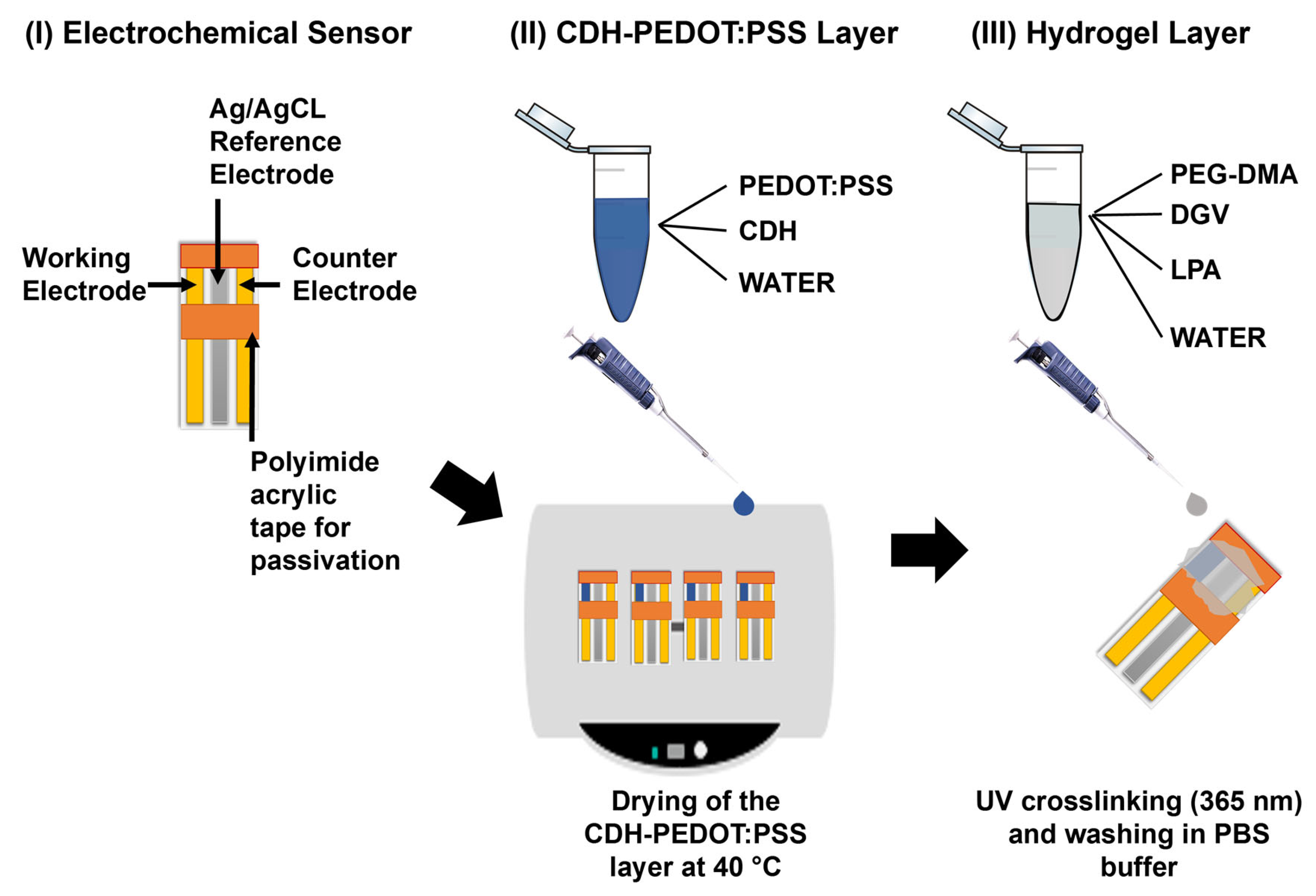
2.3. Electrode Modification

The enzymes were immobilized on vapor-deposited gold working electrodes with a 1.6 mm2 area each. The electrodes were modified by applying the following procedure (see also Figure 1):
  • PEDOT:PSS ink and CDH-PEDOT:PSS ink formulation: PEDOT:PSS ink was prepared by mixing 16% v/v PEDOT:PSS and 84% v/v ultrapure water. CDH-PEDOT:PSS ink was prepared by mixing 16% v/v PEDOT:PSS, 54% v/v ultrapure water, and 30% v/v (24 mg/mL in water) of CDH. The final concentration of CDH of 7.2 mg/mL in the ink was used in all the experiments, except in Section 3.4, “Investigation of the CDH concentration in the CDH-PEDOT:PSS ink”. An amount of 3 μL of these solutions in total was drop-casted on the working electrode of the sensors by applying six times 0.5 µL on the working electrode with drying at 40 °C for 1 min on a Präzitherm heating plate after each layer.
  • Hydrogel precursor solutions: Acrylate-based hydrogel precursor solutions were prepared by mixing 30% v/v PEG-DMA (1 kDa, 700 mg/mL in water or 10 kDa, 175 mg/mL in water), 60% v/v DEGVE, 8% v/v water, and 2% v/v of LPA (10 mg/100 µL in 50% v/v ethanol, 50% v/v water mixture). LPA (10 mg) was dissolved by ultrasonication. LPA is the UV-induced free radical photoinitiator, PEG-DMA (1 or 10 kDa) is the crosslinking substance, and DEGVE is the water-soluble monomer for chain extension.
  • An amount of 1.5 μL/mm2 of the hydrogel precursor solutions was drop-casted on the sensing area covering working, counter, and reference electrode (in total 3 µL).
  • UV crosslinking: After modification with the hydrogel precursor solution, the sensors were transferred into a UV crosslinker (UVP CL-1000 ultraviolet crosslinker, from Analytik Jena US LLC (Formerly UVP LLC), Upland, CA, USA, purchased through VWR International, Vienna, Austria) and crosslinked at 365 nm with 1 J/cm2.
  • Washing: The sensors were dipped in physiological PBS for 10 min and then 5 more min in fresh physiological PBS.
Figure 1. Modification of electrochemical sensors for glucose sensing: (I) bare electrochemical sensor, (II) CDH-PEDOT:PSS layer application, (III) hydrogel layer application.
Chemosensors 12 00036 g001

2.4. Electrochemical Measurements

The electrochemical measurements were performed using a commercial MultiEmStat3 potentiostat (PalmSens, Houten, The Netherlands) (see Supplementary Material, Figure S2) and the software Multitrace 3.6. The chronoamperometric measurements were performed using a measurement interval of 0.5 s and different potentials (−0.2, 0, 0.2, and 0.4 V) versus Ag/AgCl. During a chronoamperometric measurement, the measured current at the applied potential results from the reaction of glucose at the FAD active center of the CDH enzyme and the direct electron transfer over the CYT domain to the electrode [10,11].
Glucose detection experiments were performed either by one-time addition or stepwise addition of different concentrations of glucose in physiological PBS (pH 7.4). If not stated differently, the current densities (nA/mm2) were calculated after 500 s glucose standard addition by calculating the average of the values obtained between 400 and 500 s and by dividing the current value by an electrode area of 1.6 mm2.

2.5. Selectivity Test

To investigate the interference sensor signal caused by substances other than glucose that can be present in the body fluid, a mixed solution was prepared by dissolving all interferents in physiological PBS. The interference mix contained 40 mg/dL acetaminophen, 7.6 mg/dL ascorbic acid, 2 mg/dL dopamine, and 54 mg/dL uric acid. Chronoamperometric measurements were performed at different potentials. PBS was applied on the electrode, followed by exposing the sensor to the interference mixture after 500 s.

2.6. Operational Stability and PEG-DMA Crosslinkers with Different Molar Masses

The operational stability of the biosensors was investigated by continuous chronoamperometric measurements at 0 V in the presence of glucose. The measurements took place in an electrochemical cell system (see Supplementary Material, Figure S5). The sensors were prepared as described previously in Section 2.3 (see Figure 1). To investigate the effect of the molecular weight of PEG-DMA in the hydrogel on the current output and long-term stability, two different molecular weights of PEG-DMA (1 and 10 kDa) were used for the modification of the CDH-PEDOT:PSS (in the presence of 7.2 mg/mL CDH in the CDH-PEDOT:PSS ink) modified electrodes. A glucose concentration series was recorded for calibration purposes by adding glucose stepwise to reach 0.1, 0.5, 1, 2, 5, 10, and 20 mM glucose in the final measurement solution. After reaching the last concentration (20 mM), chronoamperometry was run further for 16 h to observe the operational decay. The measurement was performed in a bulk amount glucose solution, and the temperature was kept constant at 25 °C.

2.7. Storage Stability

Storage stability is a crucial parameter for evaluating a biosensor. To check this parameter of the electrodes, CDH-PEDOT:PSS-PEG-DMA (10 kDa) hydrogel–modified electrodes were prepared as previously described (Figure 1) with 7.2 mg/mL CDH concentration in the CDH-PEDOT:PSS ink. Sensors were dried at room temperature for 5 h and then kept at 4 °C in vacuum-packed aluminum bags with a desiccant until the specific measurement time. Electrode performance was tested by conducting chronoamperometry at 0 V with the addition of different glucose concentration standards directly onto gold or graphite NaCoS sensors without previous equilibration in buffer.

3. Results

3.1. CDH-PEDOT:PSS Layer Stability

First of all, in a preliminary study, we tested the effect of the UV treatment on the enzyme activity. CDH was stable when exposed to UV light at 302 nm up to an energy dose of 1 J/cm2, which is the energy dose applied to crosslink the hydrogel. Exposures to UV light at higher energy doses were not tested.
To investigate the stability of the CDH-PEDOT:PSS layer, two sensors without CDH enzyme (with a PEDOT:PSS layer or a PEDOT:PSS-PEG-DMA (1 kDa) layer), as negative controls, and two sensors comprising CDH enzyme (with a CDH-PEDOT:PSS layer or a CDH-PEDOT:PSS-PEG-DMA (1 kDa) layer), as glucose responsive sensors, were prepared. To test the stability, the surface modifications were inspected before (see Figure 2a) and after (see Figure 2b) intense washing (see Section 2.3, “Electrode Modification”, Step 4: Washing). Figure 2 shows the chronoamperogram at 0 V in PBS. After 1800 s, 5 mM glucose standard was applied on the sensors, while the current was further monitored. It turned out that before the washing step, CDH-PEDOT:PSS and CDH-PEDOT:PSS-PEG-DMA showed a signal response when increasing the glucose concentration. As expected, both the negative controls PEDOT:PSS and PEDOT:PSS-PEG-DMA did not show any current response. After washing, only the hydrogel-covered CDH-PEDOT:PSS-PEG-DMA layer stack yielded a current response. This indicates that CDH is still mobile in the PEDOT:PSS layer and can be washed away if this layer is not protected by a hydrogel layer (see Figure 2b). In addition, the PEDOT:PSS layer without the PEG-DMA hydrogel cover showed signs of incipient delamination.

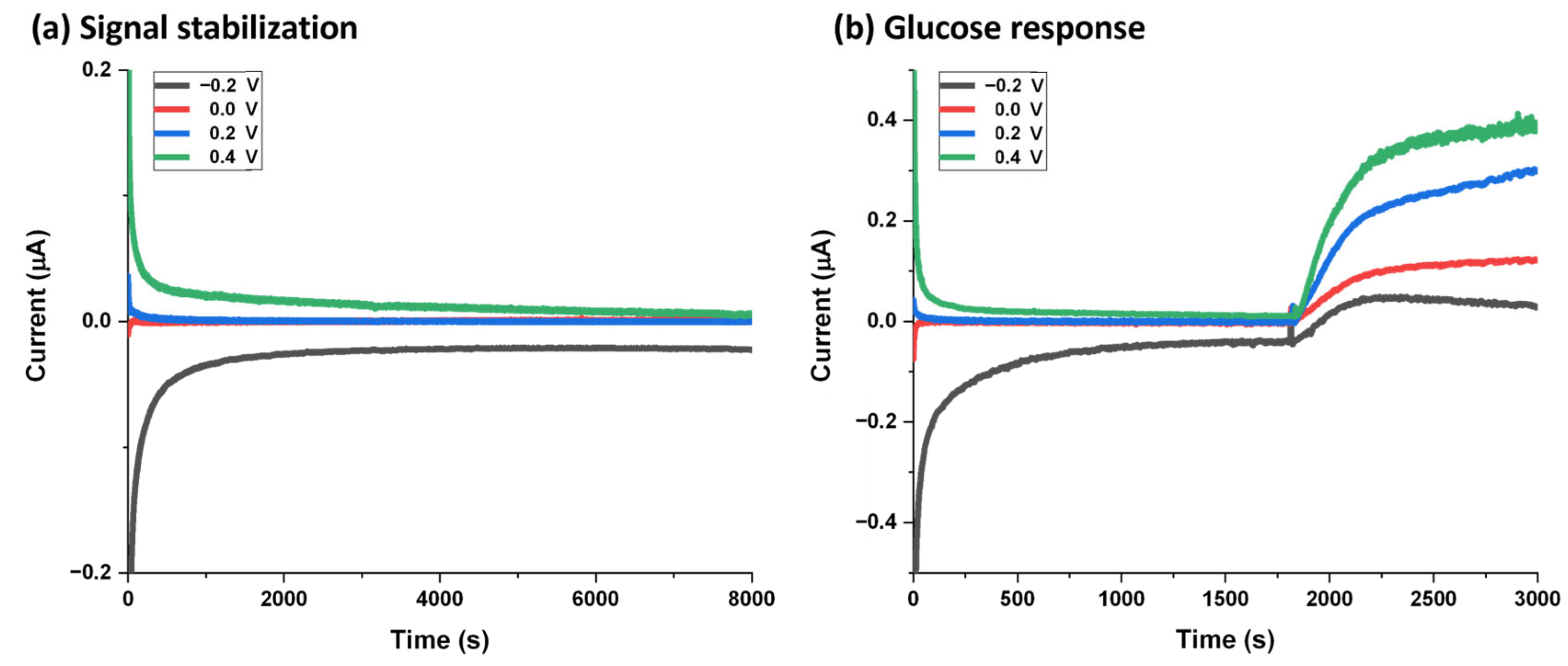
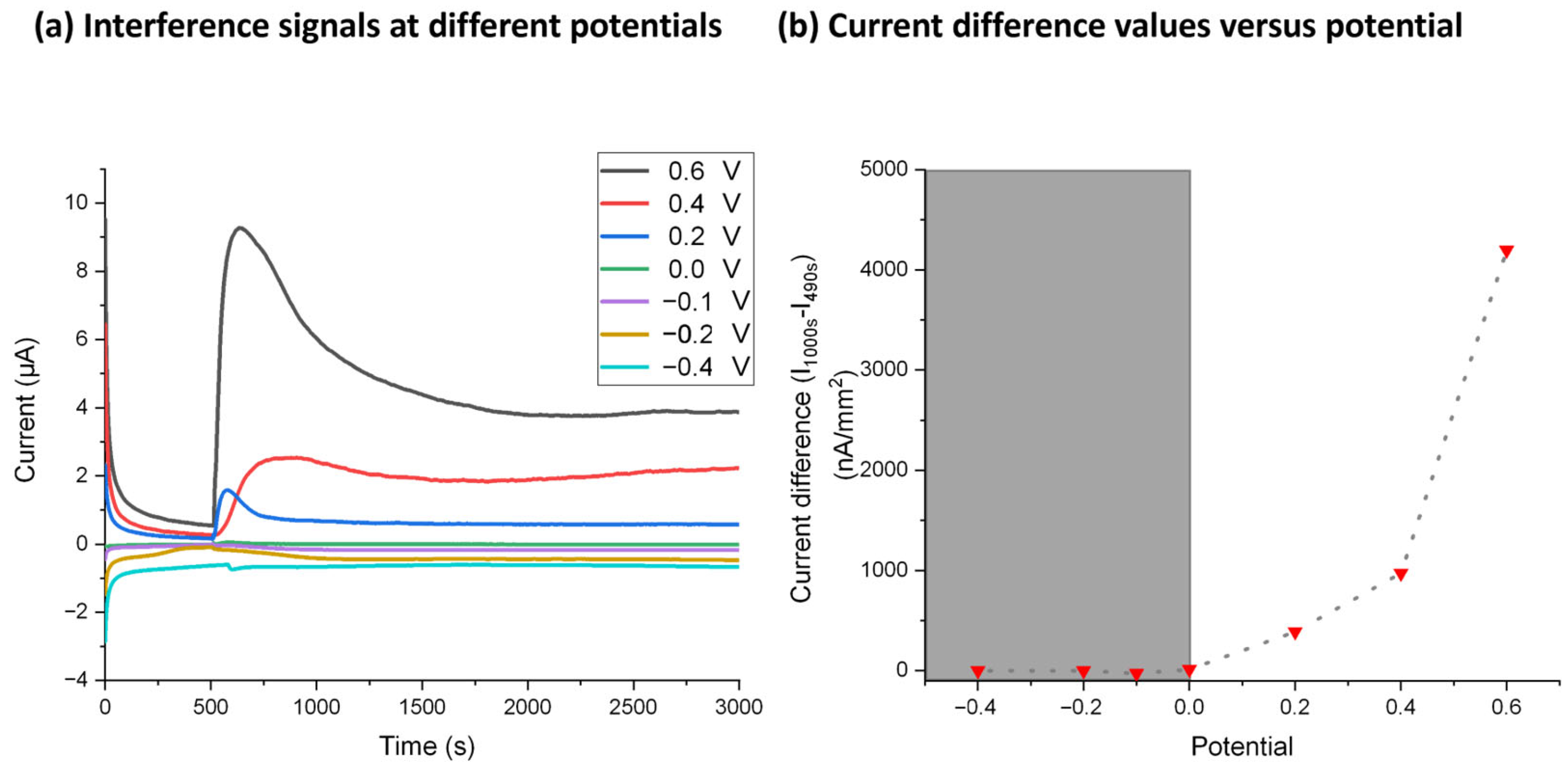
3.2. Potential Dependency of the Current Response

Chronoamperometric measurements at different potentials (−0.2–0.4 V) were performed to investigate if the current response of the blank signal and the glucose-dependent signal on the CDH-PEDOT:PSS-PEG-DMA (1 kDa) layer stack depends on the potential. For that purpose, we exposed the sensing area to physiological PBS, followed by monitoring the current response. Evidently, potentials higher or lower than 0 V lead to longer stabilization times of the blank signal but stay stable over a long period of time (up to 8000 s; see Figure 3a). To detect the glucose-dependent current, the experiment was repeated. After 1800 s, the PBS buffer was exchanged with 5 mM glucose standard to monitor the glucose-specific response for different voltages (Figure 3b). Both current densities and the corresponding standard deviations increase with increasing potential: the values are 21.9 ± 7 nA/mm2 for −0.2 V, 124 ± 38 nA/mm2 for 0 V, 305 ± 92 nA/mm2 for 0.2 V, and 522 ± 110 nA/mm2 for 0.4 V.

3.3. Selectivity Test

As mentioned, several redox-active compounds may be present in body fluids, such as acetaminophen or ascorbic acid. Independent of the applied potential, they may lead to false-positive signals and, therefore, to false readings of the glucose level. The selectivity behavior of the used DET enzyme was briefly described in a previous publication [34].
This section investigates the influence of the applied potential and the redox currents of the most relevant compounds (acetaminophen, ascorbic acid, dopamine, uric acid) on the CDH-PEDOT:PSS-PEG-DMG (1 kDa)–modified electrode. A more detailed interference study including also redox-inactive compounds is given in the Supplementary Material; see Figure S3a. As CDH-PEDOT:PSS-PEG-DMG (1 kDa) fully covers the working electrode, the respective electrode material has no influence on the signals: carbon and gold sensors lead to similar results.
Adding the interference mixture in PBS to the measuring cell results in the current signals shown in Figure 4a for different potentials. To obtain the sensor characteristic, the initial current at 490 s (I490s) was subtracted from the current at 1000 s (I1000s). This is plotted in Figure 4b against the applied potential. It was found that the interference current decay is nearly zero at potentials ≤ 0 V. The specific current of the glucose detection at 0 V is still significantly higher than the background current (see Supplementary Material, Figure S3b).

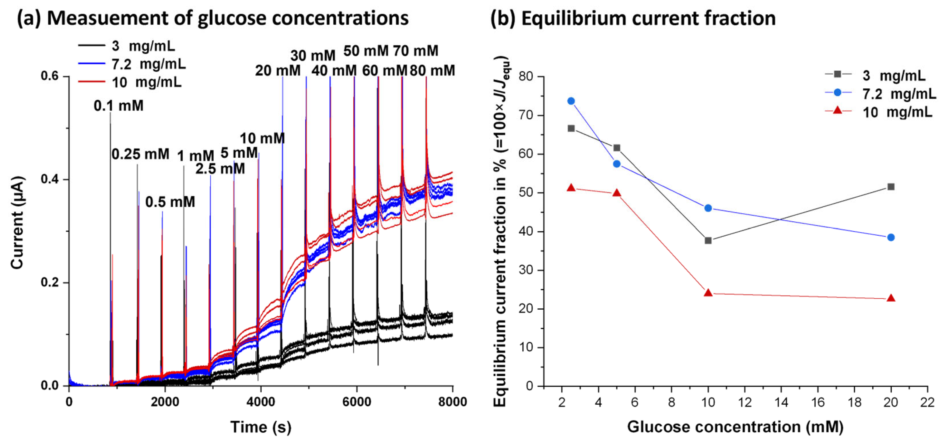
3.4. Investigation of CDH Concentration in CDH-PEDOT:PSS Ink on Sensor Responses to Glucose

All experiments took place at 0 V on sensors modified with CDH-PEDOT:PSS-PEG-DMA (1 kDa) enzyme concentrations of 3, 7.2, and 10 mg/mL. We also tested inks with higher CDH concentrations. However, concentrations ≥ 12.5 mg/mL led to poor adhesion on the gold electrodes and were, therefore, not investigated further.
Glucose detection was performed by exposing the sensors to 5 mM glucose solution after a stabilization time of 1800 s, followed by increasing the glucose concentration stepwise. Current densities were calculated for each enzyme concentration and plotted against the glucose concentration for gold (see Figure 5a) and carbon sensors (see Figure 5b).
When using 3 mg/mL CDH, currents are lower for all measured glucose concentrations than for sensors modified with 7.2 or 10 mg/mL CDH. The signals of the latter two did not significantly differ from each other at any glucose concentration. However, the standard deviations obtained from four different sensors increased with increasing CDH concentrations in the ink and were thus highest for sensors modified with 10 mg/mL CDH.

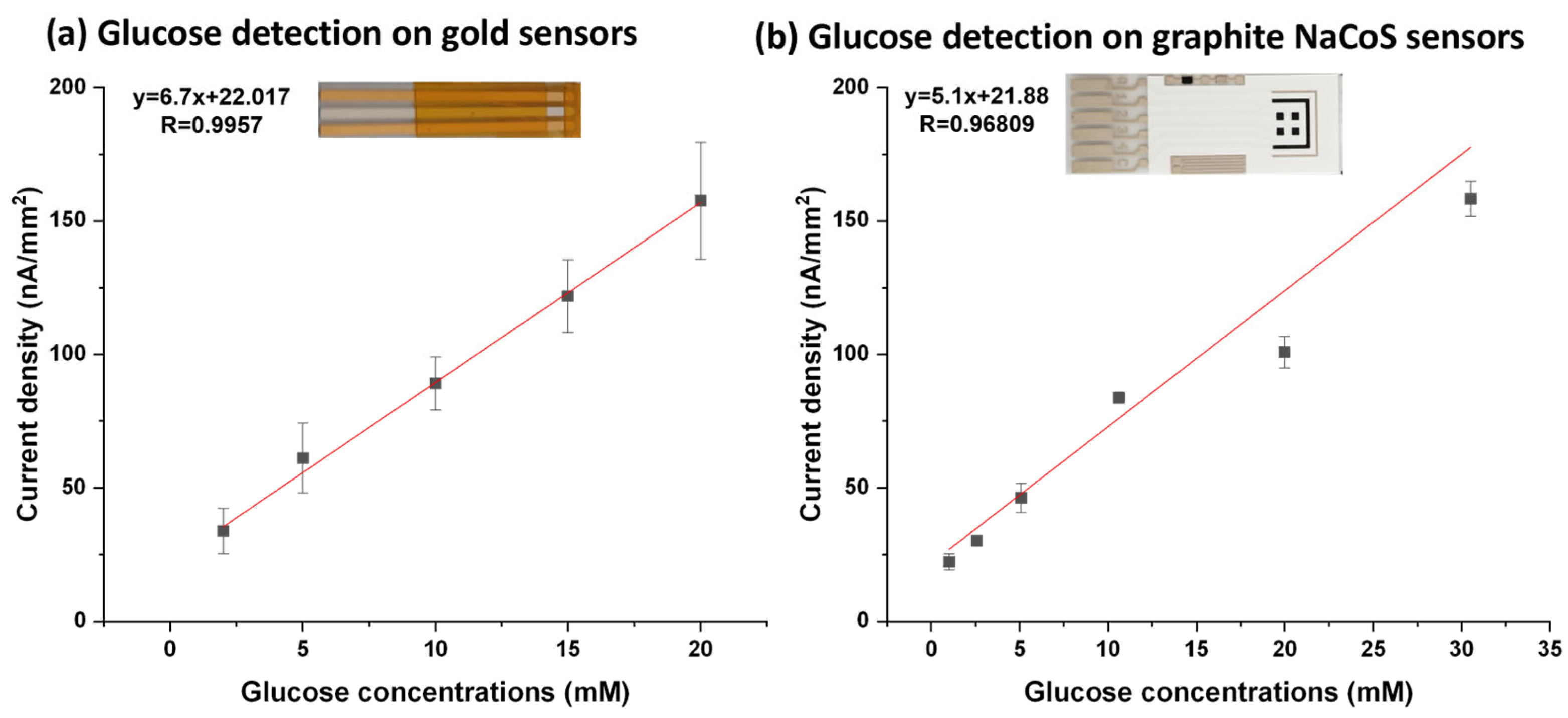
3.5. Enzyme Kinetics of Glucose Response

To show the influence of the enzyme activity and the electron transport properties of the layer stack, average current densities were plotted versus the glucose concentrations for gold sensors in Figure 5a and for graphite NaCoS sensors in Figure 5b. The obtained data points were fitted using the Michaelis–Menten equation I = Imax × ([S]/(Km + [S]), where I is the current density, Imax the maximum current density, Km the Michaelis–Menten constant, and [S] the chemical substrate concentration. As result, we found a Km value of 28.4 ± 2.2 mM on gold and a Km value of 34.2 ± 2.6 mM on graphite for an enzyme concentration of 7.2 mg/mL. The maximum current density observed on gold sensors was 257.4 ± 7.9 nA/mm2, and on graphite 170.0 ± 5.6 nA/mm2. The obtained Km values are in line with the values obtained by the company producing the enzyme on graphite electrodes with directly immobilized enzyme (Km of 24.3 ± 0.6 mM).
For further analysis of the signal stabilization time after changing the glucose concentration, the gold sensor signals plotted in Figure 6a for glucose concentrations in the range 2.5–20 mM were fitted using the equation J(t) = Jequ(1 − e−t×kequ) [35], where J is the current at time t, kequ the equilibrium rate constant, and Jequ the fitted equilibrium current. Due to the envisaged CGM application, we aim for a fast stabilization of the current response. To compare the stabilization times for different enzyme concentrations, an equilibrium current fraction was calculated for the current J at 400 s after standard addition and Jequ. These equilibrium current fractions in % (=100 × J/Jequ) were plotted for each enzyme concentration used against different glucose concentrations.
In conclusion, we observed the highest currents and best resolution in combination with a signal equilibration of 40–80% within 400 s in the physiologically relevant range glucose concentration range (0.1–20 mM) using an enzyme concentration of 7.2 mg/mL in the CDH-PEDOT:PSS ink (see Figure 6b). Hence, we chose a 7.2 mg/mL enzyme concentration in the CDH-PEDOT:PSS ink as being optimal. It provides high currents, better reproducibility, and lower impact on sensor fabrication costs.

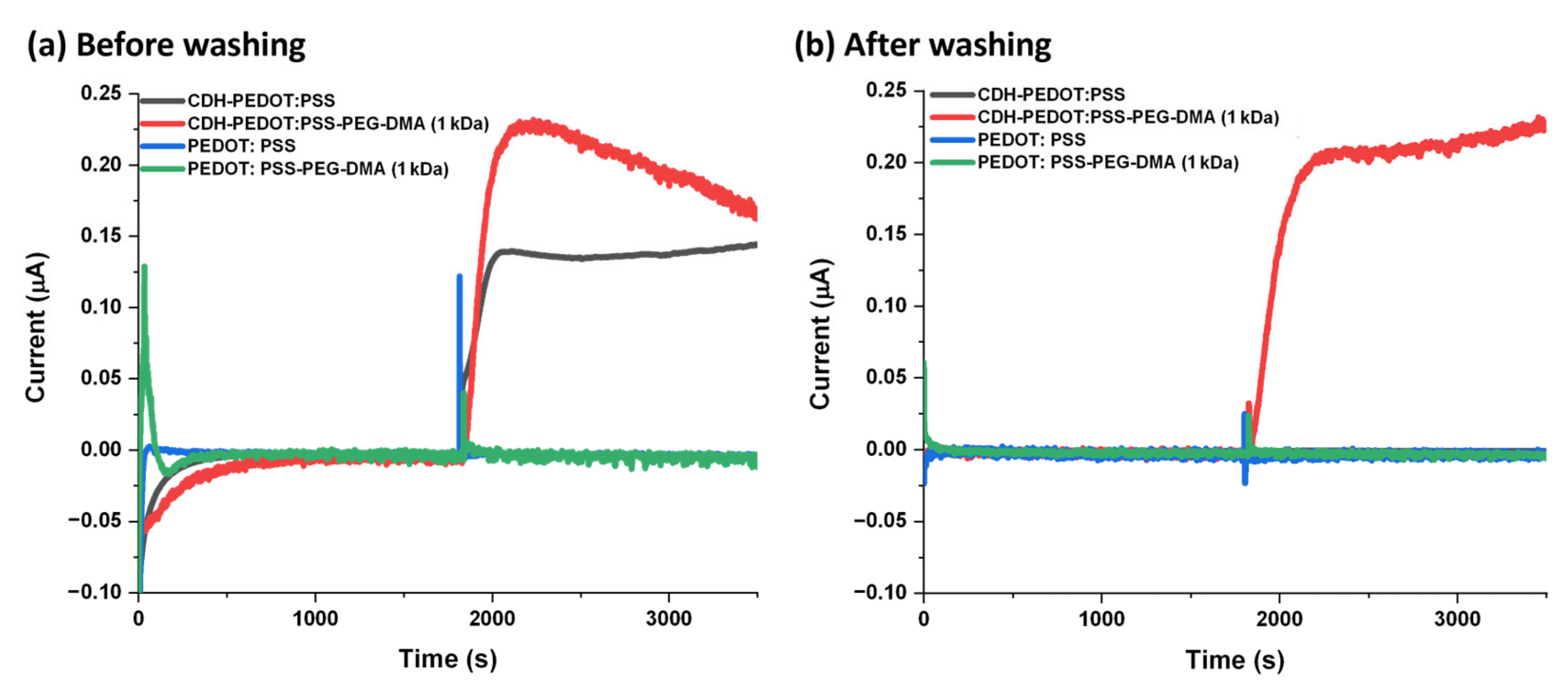
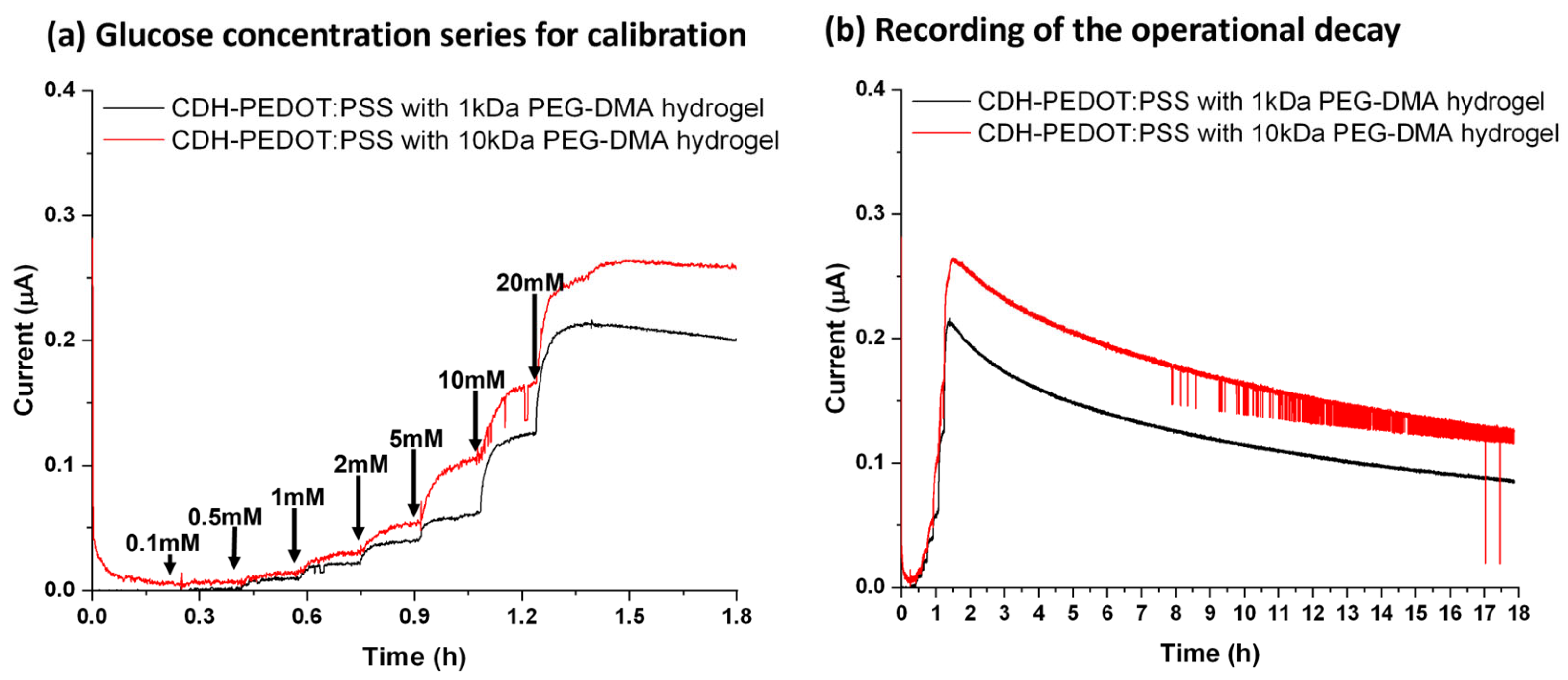
3.6. Glucose Detection in the Presence of PEG-DMA Crosslinkers with Different Molar Masses

Proper hydrogel adhesion to the underlying CDH-PEDOT:PSS layer electrode is crucial for glucose sensing because it protects the enzymatic layer and prevents enzyme leaching (see also Section 3.1). The impacts of environmental conditions and storage time on the hydrogel structure are other important parameters. Environmental conditions such as temperature, humidity, and drying conditions may affect the hydrogel structure. Consequently, hydrogel adhesion to the electrode may change, affecting sensitivity. A comparison of the 1 and 10 kDa PEG-DMA crosslinkers shows that 10 kDa PEG-DMA exhibits better adhesion (see Supplementary Material, Figure S4, showing images of the structural deformation of the hydrogels with different molecular weights on gold surfaces). Figure 7a shows glucose concentration series recorded by adding glucose stepwise; Figure 7b shows the operational decay during the continuous measurement of 20 mM glucose afterwards. Two measurement series for each PEGDMA molecular weight were performed.
Normalized currents for both types of hydrogel-coated PEDOT:PSS-CDH–modified sensors were calculated to be 100 nA/mm2. The observed current values indicate that the use of different molecular weights of PEG-DMA does not change the diffusion limitation.

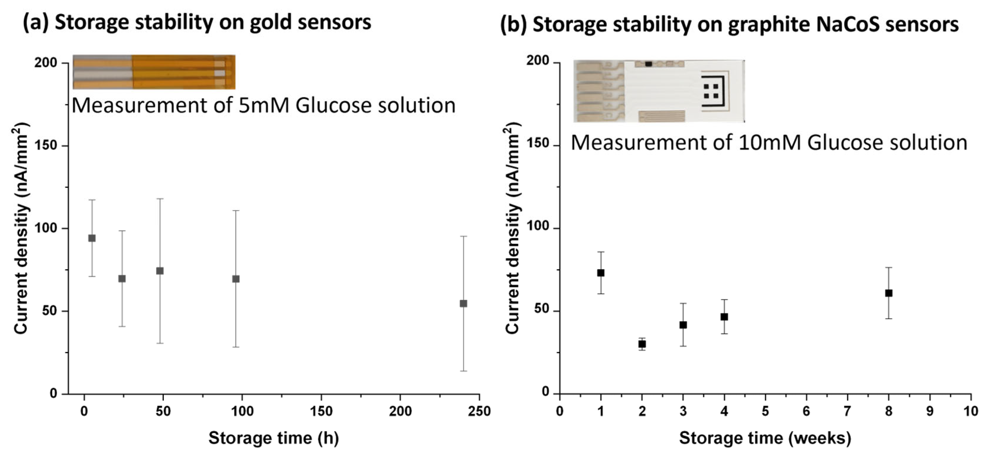
3.7. Storage Stability

The calibration curve for gold sensors is shown in Figure 8a and for graphite NaCoS sensors in Figure 8b. For both sensor types, the depicted values are the average value of the last 10 s of a 100 s measurement (number of sensors, n = 4) and are plotted against the concentrations.
To test the storage stability, the gold sensors were stored from 5 to 240 h (i.e., up to 10 days), and then measurements of 5 mM glucose were performed (see Figure 9a). On graphite NaCoS sensors, the storage stability was measured for 8 weeks in total (see Figure 9b). The results prove a good stability of the CDH-PEDOT:PSS-PEG-DMA surface modification.

4. Discussion

CDH was successfully immobilized on vapor-deposited gold electrodes by using a conductive PEDOT:PSS ink and a PEG-DMA hydrogel layer. The working principles of direct electrode transfer (DET) enzymes have been recently shown mainly on carbon-based electrodes in a working potential window > 0.1 V (see Supplementary Material, Table S1) [12,18,36,37,38]. In our work, we show that the presented modification approach of CDH-PEDOT:PSS-PEG-DMA can be applied to gold and graphite electrodes, providing a low working potential and enabling an interference-free glucose detection range (−0.2 and 0.4 V).
The maximum current density observed for gold sensors was 257.4 ± 7.9 nA/mm2, while for graphite, it was only 170.0 ± 5.5 nA/mm2. The Michaelis–Menten constants (Km) were quite similar for gold (Km = 28.4 ± 2.2 mM) and graphite (Km = 34.2 ± 2.6 mM). These findings indicate a similar electron transfer rate from CDH-PEDOT:PSS to a gold or graphite surface.
The function of the PEG-DMA layer is mainly to stabilize the enzyme layer on the sensor. Sensors with a PEG-DMA hydrogel on a PEDOT:PSS-CDH ink showed better stability in the washing process than sensors with PEDOT:PSS-CDH only. Using the 10 kDa instead of the 1 kDa PEG-DMA crosslinker led to the reduction of stress in the drying hydrogel layer and improved the stability of the hydrogel layer. This resulted in a good storage stability of the sensors after vacuum drying. However, no significant effect of different molecular weights of PEG-DMA was found on diffusion limitation.
The measurement range (0–80 mM), dynamic range (0.1–20 mM), and limit of detection (0.1 mM) of our presented gold sensor match with the demands for glucose sensing approaches [1] and are quite close to the reported results found in the literature (see Supplementary Material, Table S1) [12,18,36,37,38].
Regarding stability, the measurement setup and approaches can be quite different. For example, in [36], the biosensor is kept in a buffer solution inside a flow injection analysis system, where it is used for one measurement per day in the presence of 750 µM glucose. After 20 days, the biosensor retains about 90% of the initial activity. Instead, in [12], the biosensors are stored in a refrigerator and measured once per day in 5.5 mM glucose solution. After measurement, they are rinsed in buffer solution and stored again until the next day. Over 6 days, the stability was maintained at 80%, and then decreased to 50% after further 4 days. Regarding the dried gold biosensors presented here, the storage stability has been evaluated by preparing a batch of biosensors and measuring a set of four of them in the presence of 5 mM of glucose at different storage times. The relative high error bars would be reduced by substituting the manual surface modification process with an automated dispensing one. Considering the average values, after 24 h, a reduction to 85% of the initial signal is observed, and after 10 days, the signal is reduced to 70% of the initial signal. In the case of graphite biosensors, after 1 week, the signal is reduced to 45%, but seems to recover and reaches 80% of the initial signal after 8 weeks. Regarding operational stability, we evaluated it by continuously measuring the gold biosensors while exposed to 20 mM glucose solution. After 16 h, the signal decreased to 60% of its initial value. The signal reduction due to storage and operational reasons needs to be evaluated further in subsequent device development phases and has to be taken into account in the algorithms for the signal analysis.
A peculiarity of our CDH-PEDOT:PSS-PEG-DMA modification approach is that it can be applied for both planar biosensors for in vitro measurements and microneedle-based biosensors [39,40,41] for in vivo glucose monitoring in the interstitial dermal fluid (ISF). In the first case, graphite is one of the most used materials for screen-printed single-use planar sensors. In the case of microneedle-based biosensors, the most used electrode materials are thin film gold and platinum layers, which, deposited by vapor metal deposition, form a homogeneous conductive film. The use of thin film technology facilitates the integration of such microneedle-based biosensors in fully self-sustained disposable smart patches capable of independent measurements and secure wireless data transmission to the user’s mobile phone [42]. To this end, wearable smart patches comprise energy supplies and microchips combining the functionalities of a potentiostat and wireless data transfer. These devices could be used not only by individuals with chronic diseases, but anyone who might need them only occasionally for a monitoring time of 12–24 h. Examples of use cases are the early detection of (pre-) diabetes mellitus or the achievement of a healthier lifestyle through behavioral changes based on the interpretation of glucose data [43].
The CDH-PEDOT:PSS-PEG-DMA surface modification of gold layers has the advantage of fulfilling the requirements to be used in minimally invasive smart patches. First of all, microneedle-based biosensors should be biocompatible, which is possible because no toxic mediators or components are used. Then, an interference-free glucose detection is required, which we showed to be possible, for example, at a voltage of 0 V. In addition, low voltages for performing electrochemical measurements facilitate the integration with miniaturized potentiostats and reduce energy consumption. Furthermore, storage stability in the dry state needs to be guaranteed, which was tested up to 10 days on gold surfaces and 8 weeks on graphite surfaces. Moreover, operational stability for 12–24 h while continuously measuring glucose is necessary, which we assessed for 16 h. A further key aspect is the possibility to upscale the fabrication of microneedle-based biosensors in a cost-effective way. This would be enabled by the use of mass fabrication techniques such as injection molding for microneedles, vapor metal deposition for the definition of electrodes, and automated dispensing for surface modification.
As an outlook, in order to adapt our methodology to the development of such kind of microneedle-based biosensors, several steps are necessary. First of all, a reliable and reproducible automated deposition process for applying surface modification on metallized microneedles has to be developed. Then, a sterilization process compatible with the modified microneedle-based biosensors has to be identified, and the impact of such sterilization on the microneedle-based biosensors’ performances has to be investigated. Afterwards, biocompatibility tests (cytotoxicity, skin sensitization, skin irritation) need to be performed as prerequisites for the application of the biosensor on the human body. Finally, a clinical study that would perform in vivo measurements is necessary to compare the results of the microneedle-based biosensor in ISF with the glucose levels measured in the blood using standard laboratory equipment.

Supplementary Materials

The following supporting information can be downloaded at https://www.mdpi.com/article/10.3390/chemosensors12030036/s1: Figure S1: Sensor design of (a) NaCoS sensors, (b) vapor-deposited gold sensor; Figure S2: Photograph of the measurement setup: (1) computer, (2) potentiostat, (3) connector, (4) vapor-deposited gold sensor; Figure S3: (a) Interference signals on CDH-PEDOT:PSS-PEG-DMA–modified carbon sensor at 0.0 V by exchanging liquids containing glucose (5 mM) with either acetaminophen (20 mg/dL), ascorbic acid (3 mg/dL), dopamine (13 mg/dL), maltose (2650 mg/dL), or galactose (81 mg/dL). (b) Specific signal (5 mM Glucose) on gold sensors versus nonspecific signal (interference mixture: 40 mg/dL acetaminophen, 7.6 mg/dL ascorbic acid, 2 mg/dL dopamine, and 54 mg/dL uric acid) at 0.0 V chronoamperometry; Figure S4: Light microscopic images of drop-casted hydrogels having PEG-DMA with different molar masses after drying at 25 °C for 1 day: (a) hydrogel with 1 kDa PEG-DMA on bare gold surface, (b) hydrogel with 10 kDa PEG-DMA on bare gold surface, (c) hydrogel with 1 kDa PEG-DMA on MPA-modified gold surfaces, and (d) hydrogel with 10 kDa PEG-DMA on MPA-modified gold surfaces; Figure S5: Image of the high-volume setup used for the investigation of operational stability of the CDH-PEDOT:PSS-PEG-DMA (1 and 10 kDa)–modified sensors; Table S1: Comparison of DET-enzyme-based sensors for glucose detection.

Author Contributions

Conceptualization, E.M., G.C.M. and R.H.; data curation, E.M.; formal analysis, E.M.; funding acquisition, E.M., G.C.M. and R.H.; investigation, E.C., E.M., S.K. and P.P.; methodology, E.M., G.C.M. and R.H.; project administration, G.C.M.; supervision, E.M., G.C.M., R.H. and P.L.; validation, E.C., E.M., S.K. and P.P.; visualization, E.C., P.P. and E.M.; writing—original draft, E.C.; writing—review and editing, E.M., S.K., G.C.M., R.H., A.K.G.F., C.S. and P.L. All authors have read and agreed to the published version of the manuscript.

Funding

This research was funded by the Austrian Research Promotion Agency (FFG), grant agreement no. 858701 (NUMBAT project), and by the European Union’s Horizon 2020 research and innovation program, grant agreement no. 825549 (ELSAH project).

Institutional Review Board Statement

Not applicable.

Informed Consent Statement

Not applicable.

Data Availability Statement

Data are contained within the article and Supplementary Materials.

Conflicts of Interest

A.K.G.F. is a cofounder and C.S. is employee of a company, DirectSens GmbH, involved in the commercialization of enzyme-based sensor technology. The remaining authors declare that the research was conducted in the absence of any commercial or financial relationships that could be construed as a potential conflict of interest.

References

  1. Güemes, M.; Rahman, S.A.; Hussain, K. What is a normal blood glucose? Arch. Dis. Child. 2016, 101, 569–574. [Google Scholar] [CrossRef]
  2. Vashist, S.K. Point-of-Care Glucose Detection for Diabetic Monitoring and Management, 1st ed.; Taylor & Francis Group: Boca Raton, FL, USA, 2017; ISBN 978-1-4987-8875-5. [Google Scholar]
  3. Wang, Y.-F.; Jia, W.-P.; Wu, M.-H.; Chien, M.-O.; Hsieh, M.-C.; Wang, C.-P.; Lee, M.-S. Accuracy Evaluation of 19 Blood Glucose Monitoring Systems Manufactured in the Asia-Pacific Region: A Multicenter Study. J. Diabetes Sci. Technol. 2017, 11, 953–965. [Google Scholar] [CrossRef]
  4. Soskolne, W.A.; Klinger, A. The relationship between periodontal diseases and diabetes: An overview. Ann. Periodontol. 2001, 6, 91–98. [Google Scholar] [CrossRef]
  5. Papatheodorou, K.; Banach, M.; Bekiari, E.; Rizzo, M.; Edmonds, M. Complications of Diabetes 2017. J. Diabetes Res. 2018, 2018, 3086167. [Google Scholar] [CrossRef]
  6. Al Hayek, A.A.; Robert, A.A.; Al Dawish, M.A. Evaluation of FreeStyle Libre Flash Glucose Monitoring System on Glycemic Control, Health-Related Quality of Life, and Fear of Hypoglycemia in Patients with Type 1 Diabetes. Clin. Med. Insights Endocrinol. Diabetes 2017, 10, 1179551417746957. [Google Scholar] [CrossRef]
  7. Tehrani, F.; Teymourian, H.; Wuerstle, B.; Kavner, J.; Patel, R.; Furmidge, A.; Aghavali, R.; Hosseini-Toudeshki, H.; Brown, C.; Zhang, F.; et al. An integrated wearable microneedle array for the continuous monitoring of multiple biomarkers in interstitial fluid. Nat. Biomed. Eng. 2022, 6, 1214–1224. [Google Scholar] [CrossRef]
  8. Ju, J.; Li, L.; Regmi, S.; Zhang, X.; Tang, S. Microneedle-Based Glucose Sensor Platform: From Vitro to Wearable Point-of-Care Testing Systems. Biosensors 2022, 12, 606. [Google Scholar] [CrossRef]
  9. Gallaway, J.W.; Calabrese Barton, S.A. Kinetics of redox polymer-mediated enzyme electrodes. J. Am. Chem. Soc. 2008, 130, 8527–8536. [Google Scholar] [CrossRef]
  10. Estrada-Osorio, D.V.; Escalona-Villalpando, R.A.; Gutiérrez, A.; Arriaga, L.G.; Ledesma-García, J. Poly-L-lysine-modified with ferrocene to obtain a redox polymer for mediated glucose biosensor application. Bioelectrochemistry 2022, 146, 108147. [Google Scholar] [CrossRef]
  11. Ramanavicius, A.; Rekertaitė, A.I.; Valiūnas, R.; Valiūnienė, A. Single-step procedure for the modification of graphite electrode by composite layer based on polypyrrole, Prussian blue and glucose oxidase. Sens. Actuator B Chem. 2017, 240, 220–223. [Google Scholar] [CrossRef]
  12. Jeon, W.-Y.; Kim, H.-S.; Jang, H.-W.; Lee, Y.-S.; Shin, U.S.; Kim, H.-H.; Choi, Y.-B. A stable glucose sensor with direct electron transfer, based on glucose dehydrogenase and chitosan hydro bonded multi-walled carbon nanotubes. Biochem. Eng. J. 2022, 187, 108595. [Google Scholar] [CrossRef]
  13. Cai, Y.; Tu, T.; Li, T.; Zhang, S.; Zhang, B.; Fang, L.; Ye, X.; Liang, B. Research on direct electron transfer of native glucose oxidase at PEDOT:PSS hydrogels modified electrode. J. Electroanal. Chem. 2022, 922, 116738. [Google Scholar] [CrossRef]
  14. Chen, J.; Zheng, X.; Li, Y.; Zheng, H.; Liu, Y.; Suye, S. A Glucose Biosensor Based on Direct Electron Transfer of Glucose Oxidase on PEDOT Modified Microelectrode. J. Electrochem. Soc. 2020, 167, 67502. [Google Scholar] [CrossRef]
  15. Bollella, P. Enzyme-based amperometric biosensors: 60 years later … Quo Vadis? Anal. Chim. Acta 2022, 1234, 340517. [Google Scholar] [CrossRef]
  16. Bartlett, P.N.; Al-Lolage, F.A. There is no evidence to support literature claims of direct electron transfer (DET) for native glucose oxidase (GOx) at carbon nanotubes or graphene. J. Electroanal. Chem. 2018, 819, 26–37. [Google Scholar] [CrossRef]
  17. Wilson, G.S. Native glucose oxidase does not undergo direct electron transfer. Biosens. Bioelectron. 2016, 82, 7–8. [Google Scholar] [CrossRef]
  18. Jayakumar, K.; Reichhart, T.M.B.; Schulz, C.; Ludwig, R.; Felice, A.K.G.; Leech, D. An Oxygen Insensitive Amperometric Glucose Biosensor Based on An Engineered Cellobiose Dehydrogenase: Direct versus Mediated Electron Transfer Responses. ChemElectroChem 2022, 9, e202200418. [Google Scholar] [CrossRef]
  19. Larsson, T.; Lindgren, A.; Ruzgas, T.; Lindquist, S.E.; Gorton, L. Bioelectrochemical characterisation of cellobiose dehydrogenase modified graphite electrodes: Ionic strength and pH dependences. J. Electroanal. Chem. 2000, 482, 1–10. [Google Scholar] [CrossRef]
  20. Lindgren, A.; Gorton, L.; Ruzgas, T.; Baminger, U.; Haltrich, D.; Schülein, M. Direct electron transfer of cellobiose dehydrogenase from various biological origins at gold and graphite electrodes. J. Electroanal. Chem. 2001, 496, 76–81. [Google Scholar] [CrossRef]
  21. Bollella, P.; Mazzei, F.; Favero, G.; Fusco, G.; Ludwig, R.; Gorton, L.; Antiochia, R. Improved DET communication between cellobiose dehydrogenase and a gold electrode modified with a rigid self-assembled monolayer and green metal nanoparticles: The role of an ordered nanostructuration. Biosens. Bioelectron. 2017, 88, 196–203. [Google Scholar] [CrossRef]
  22. Kielb, P.; Sezer, M.; Katz, S.; Lopez, F.; Schulz, C.; Gorton, L.; Ludwig, R.; Wollenberger, U.; Zebger, I.; Weidinger, I.M. Spectroscopic Observation of Calcium-Induced Reorientation of Cellobiose Dehydrogenase Immobilized on Electrodes and its Effect on Electrocatalytic Activity. ChemPhysChem 2015, 16, 1960–1968. [Google Scholar] [CrossRef]
  23. Bollella, P.; Ludwig, R.; Gorton, L. Cellobiose dehydrogenase: Insights on the nanostructuration of electrodes for improved development of biosensors and biofuel cells. Appl. Mater. Today 2017, 9, 319–332. [Google Scholar] [CrossRef]
  24. Feifel, S.C.; Ludwig, R.; Gorton, L.; Lisdat, F. Catalytically active silica nanoparticle-based supramolecular archi-tectures of two proteins--cellobiose dehydrogenase and cytochrome C on electrodes. Langmuir 2012, 28, 9189–9194. [Google Scholar] [CrossRef]
  25. Ma, S.; Ludwig, R. Direct Electron Transfer of Enzymes Facilitated by Cytochromes. ChemElectroChem 2019, 6, 958–975. [Google Scholar] [CrossRef]
  26. Gerwig, R.; Fuchsberger, K.; Schroeppel, B.; Link, G.S.; Heusel, G.; Kraushaar, U.; Schuhmann, W.; Stett, A.; Stelzle, M. PEDOT–CNT Composite Microelectrodes for Recording and Electrostimulation Applications: Fabrication, Morphology, and Electrical Properties. Front. Neuroeng. 2012, 5, 1–11. [Google Scholar] [CrossRef]
  27. Pranti, A.S.; Schander, A.; Bödecker, A.; Lang, W. PEDOT: PSS coating on gold microelectrodes with excellent stability and high charge injection capacity for chronic neural interfaces. Sens. Actuators B Chem. 2018, 275, 382–393. [Google Scholar] [CrossRef]
  28. Wang, Z.; Xu, J.; Yao, Y.; Zhang, L.; Wen, Y.; Song, H.; Zhu, D. Facile preparation of highly water-stable and flexible PEDOT:PSS organic/inorganic composite materials and their application in electrochemical sensors. Sens. Actuators B Chem. 2014, 196, 357–369. [Google Scholar] [CrossRef]
  29. Fan, X.; Nie, W.; Tsai, H.; Wang, N.; Huang, H.; Cheng, Y.; Wen, R.; Ma, L.; Yan, F.; Xia, Y. PEDOT:PSS for Flexible and Stretchable Electronics: Modifications, Strategies, and Applications. Adv. Sci. 2019, 6, 1900813–1900853. [Google Scholar] [CrossRef]
  30. Riegel, A.-L.; Borzenkova, N.; Haas, V.; Scharfer, P.; Schabel, W. Activity determination of FAD-dependent glucose dehydrogenase immobilized in PEDOT: PSS-PVA composite films for biosensor applications. Eng. Life Sci. 2016, 16, 577–585. [Google Scholar] [CrossRef]
  31. Lin-Gibson, S.; Bencherif, S.; Cooper, J.A.; Wetzel, S.J.; Antonucci, J.M.; Vogel, B.M.; Horkay, F.; Washburn, N.R. Synthesis and characterization of PEG dimethacrylates and their hydrogels. Biomacromolecules 2004, 5, 1280–1287. [Google Scholar] [CrossRef]
  32. Yin, R.; Wang, K.; Han, J.; Nie, J. Photo-crosslinked glucose-sensitive hydrogels based on methacrylate modified dextran–concanavalin A and PEG dimethacrylate. Carbohydr. Polym. 2010, 82, 412–418. [Google Scholar] [CrossRef]
  33. Ludwig, R.; Sygmund, C.; Harreither, W.; Kittl, R.; Felice, A.K.G. Mutated Cellobiose Dehydrogenase with Increased Substrate Specificity. Granted Patent US 2015083611 A1; USA, 26 March 2015. [Google Scholar]
  34. Felice, A.K.G.; Sygmund, C.; Harreither, W.; Kittl, R.; Gorton, L.; Ludwig, R. Substrate specificity and interferences of a direct-electron-transfer-based glucose biosensor. J. Diabetes Sci. Technol. 2013, 7, 669–677. [Google Scholar] [CrossRef]
  35. Jarmoskaite, I.; AlSadhan, I.; Vaidyanathan, P.P.; Herschlag, D. How to measure and evaluate binding affinities. eLife 2020, 9, e57264. [Google Scholar] [CrossRef]
  36. Bollella, P.; Gorton, L.; Ludwig, R.; Antiochia, R. A Third Generation Glucose Biosensor Based on Cellobiose Dehydrogenase Immobilized on a Glassy Carbon Electrode Decorated with Electrodeposited Gold Nanoparticles: Characterization and Application in Human Saliva. Sensors 2017, 17, 1912. [Google Scholar] [CrossRef]
  37. Ito, K.; Okuda-Shimazaki, J.; Mori, K.; Kojima, K.; Tsugawa, W.; Ikebukuro, K.; Lin, C.-E.; La Belle, J.; Yoshida, H.; Sode, K. Designer fungus FAD glucose dehydrogenase capable of direct electron transfer. Biosens. Bioelectron. 2019, 123, 114–123. [Google Scholar] [CrossRef]
  38. Ito, K.; Okuda-Shimazaki, J.; Kojima, K.; Mori, K.; Tsugawa, W.; Asano, R.; Ikebukuro, K.; Sode, K. Strategic design and improvement of the internal electron transfer of heme b domain-fused glucose dehydrogenase for use in direct electron transfer-type glucose sensors. Biosens. Bioelectron. 2021, 176, 112911–112917. [Google Scholar] [CrossRef]
  39. Cass, A.E.G.; Sharma, S. Microneedle Enzyme Sensor Arrays for Continuous In Vivo Monitoring. Methods Enzymol. 2017, 589, 413–427. [Google Scholar] [CrossRef]
  40. Kai, H.; Kumatani, A. A porous microneedle electrochemical glucose sensor fabricated on a scaffold of a polymer monolith. J. Phys. Energy 2021, 3, 024006–024014. [Google Scholar] [CrossRef]
  41. Bollella, P.; Sharma, S.; Cass, A.E.G.; Tasca, F.; Antiochia, R. Minimally Invasive Glucose Monitoring Using a Highly Porous Gold Microneedles-Based Biosensor: Characterization and Application in Artificial Interstitial Fluid. Catalysts 2019, 7, 580. [Google Scholar] [CrossRef]
  42. H2020 ELSAH Project. Available online: www.elsah.researchproject.at (accessed on 25 January 2024).
  43. Brinkmann, C.; Bloch, W.; Mutinati, G.C. ELSAH (Electronic smart patch system for wireless monitoring of molecular biomarkers for healthcare and well-being): Definition of possible use cases. Front. Bioeng. Biotechnol. 2023, 11, 1–6. [Google Scholar] [CrossRef]
Figure 2. Chronoamperometric measurements at 0.0 V, RT, on negative control layers (PEDOT:PSS, PEDOT:PSS-PEG-DMA (1 kDa)) and CDH containing layers (CDH-PEDOT:PSS and CDH-PEDOT:PSS-PEG-DMA (1 kDa)). At 1800 s, PBS buffer was exchanged with 5 mM glucose standard (a) before intense washing and (b) after intense washing of the layers.
Chemosensors 12 00036 g002
Figure 3. Chronoamperometric measurements at 0.0 V, RT, of (a) signal stabilization: CDH-PEDOT:PSS-PEG-DMA (1 kDa) hydrogel–modified sensors in PBS without glucose addition; (b) glucose response: 5 mM glucose detection at different applied potentials on CDH-PEDOT:PSS-PEG-DMA (1 kDa) hydrogel–modified gold electrodes.
Chemosensors 12 00036 g003
Figure 4. (a) Interference signals for a mixture of added interferents at different potentials in PBS at RT; (b) current differences (calculated as current at 1000 s (I1000s) minus blank current at 490 s (I490s)) versus applied potential.
Chemosensors 12 00036 g004
Figure 5. (a) Gold sensors: average current densities (n = 4) versus glucose concentrations measured at 0.0 V and at RT with Michaelis–Menten fit for different enzyme concentrations (black: 3 mg/mL, blue: 7.2 mg/mL, red: 10 mg/mL); (b) graphite NaCoS sensors: current densities (n = 1) vs. glucose concentrations with Michaelis–Menten fit for different enzyme concentrations (black: 3 mg/mL, blue: 7.2 mg/mL).
Chemosensors 12 00036 g005
Figure 6. (a) Sensing of glucose at 0.0 V at RT by stepwise exchange of glucose standards from the lowest (0.1 mM) to the highest concentration (80 mM) on CDH-PEDOT:PSS-PEG-DMA (1 kDa) surfaces. The spikes are artifacts caused by the exchange of solution during the in vitro measurement and would not appear in an in vivo measurement. (b) Equilibrium current fraction calculated for 2.5, 5, 10, and 20 mM glucose for the three enzyme concentrations.
Chemosensors 12 00036 g006
Figure 7. Chronoamperometry curves at 0 V and 25 °C for (a) glucose concentration series for calibration; (b) for recording of the operational decay during the continuous measurement of 20 mM glucose, performed after the glucose concentration series.
Chemosensors 12 00036 g007
Figure 8. Calibration curve at 0 V and 25 °C for (a) dried CDH-PEDOT:PSS-PEG-DMA–modified gold sensor sensors and (b) dried CDH-PEDOT:PSS-PEG-DMA–modified graphite NaCoS sensors.
Chemosensors 12 00036 g008
Figure 9. Storage stability test of the modified (a) gold and (b) graphite NaCoS sensors.
Chemosensors 12 00036 g009
Disclaimer/Publisher’s Note: The statements, opinions and data contained in all publications are solely those of the individual author(s) and contributor(s) and not of MDPI and/or the editor(s). MDPI and/or the editor(s) disclaim responsibility for any injury to people or property resulting from any ideas, methods, instructions or products referred to in the content.

