1. Introduction
Gas sensor systems are pivotal across diverse sectors, including environmental monitoring, industrial safety, healthcare, home automation, automotive applications, and scientific research [
1,
2,
3]. These technologies play a crucial role in detecting hazardous gases, monitoring air quality, ensuring workplace and public safety, diagnosing health conditions, and enhancing environmental protection [
4,
5]. The development and innovation in gas sensor technology aim to improve sensor performance in terms of sensitivity, selectivity, and reliability, while also making them more cost-effective, energy efficient, and compatible with modern wireless and IoT platforms [
6,
7].
The development of a gas sensor readout integrated circuit (ROIC) is an important technical element within the broader architecture of a gas sensor system [
8,
9,
10]. This importance stems from the ROIC’s pivotal role in accurately converting and processing the physical gas presence into electrical signals that can be understood and acted upon by the system. A well-designed ROIC not only enhances the performance of gas sensors but also significantly contributes to the overall efficiency, reliability, and applicability of gas-sensing technology across various fields. For instance, incorporating temperature modulation and pulsed heating techniques can refine the selectivity and sensitivity of the sensors, enabling them to distinguish between gases more accurately and respond faster to gas presence [
11,
12,
13,
14]. Additionally, advanced signal processing algorithms, including machine learning and statistical analysis, can be integrated to enhance detection capabilities, especially for low-concentration gases, and to minimize false positives [
15,
16]. Furthermore, adaptive baseline management within the ROIC can counteract sensor drift and environmental changes, ensuring sustained accuracy and reliability over time [
17,
18,
19].
Among the various challenges faced by gas sensor technology, selectivity remains a significant issue, with sensors often struggling to distinguish between different gases in complex environments [
20,
21]. Recent research efforts are focused on addressing this selectivity challenge by employing signal extraction from multi-gas sensor arrays and analyzing these signals through pattern recognition or signal characteristic analysis [
22,
23]. This approach aims to enhance the ability of gas sensors to accurately identify specific gases by examining the unique patterns or features present in the signals obtained from multiple sensing channels. However, it is important to note that while simultaneously extracting signals from gas sensors using a multi-gas sensor array approach can improve selectivity, it also introduces a challenge in the form of baseline distribution problems [
17,
24,
25]. This issue arises because each sensor in the array may have a different baseline signal level, which can reduce the accuracy of signal extraction when analyzing complex gas mixtures. Addressing this problem often requires the use of complex signal processing algorithms or significant computing resources to accurately interpret the data and distinguish between different gases. This requirement for advanced processing capabilities and the associated costs can be a factor that diminishes the technological competitiveness of gas sensor systems. Efficiently managing the baseline distribution and processing complexity is, therefore, important in developing competitive and effective gas sensor technologies.
In this paper, we implement a multi-gas sensor array unit with a proposed ROIC structure that effectively extracts signals from multiple gas sensors without being affected by the baseline distribution of each sensor. It is equipped with a baseline calibration technique that can utilize the fully dynamic range (DR) of the ROIC without loss of DR caused by the baseline dispersion of the gas sensor. Thus, there is no need for separate computing resources for baseline calibration, and signal extraction is possible in real time. Therefore, it is possible to improve the performance and miniaturize the overall gas sensor system, thereby securing technological competitiveness. In this paper, we implement the prototype ROIC for signal extraction of the multi-gas sensor array and verify the effectiveness of the baseline calibration technique.
The rest of this paper is organized as follows.
Section 2 discusses the structure of the multi-gas sensor array and its associated issues.
Section 3 describes the proposed ROIC design, which incorporates a baseline calibration scheme.
Section 4 presents the experimental results obtained with the prototype chip. Finally,
Section 5 provides the conclusion.
2. Structure of a Multi-Array Gas Sensor
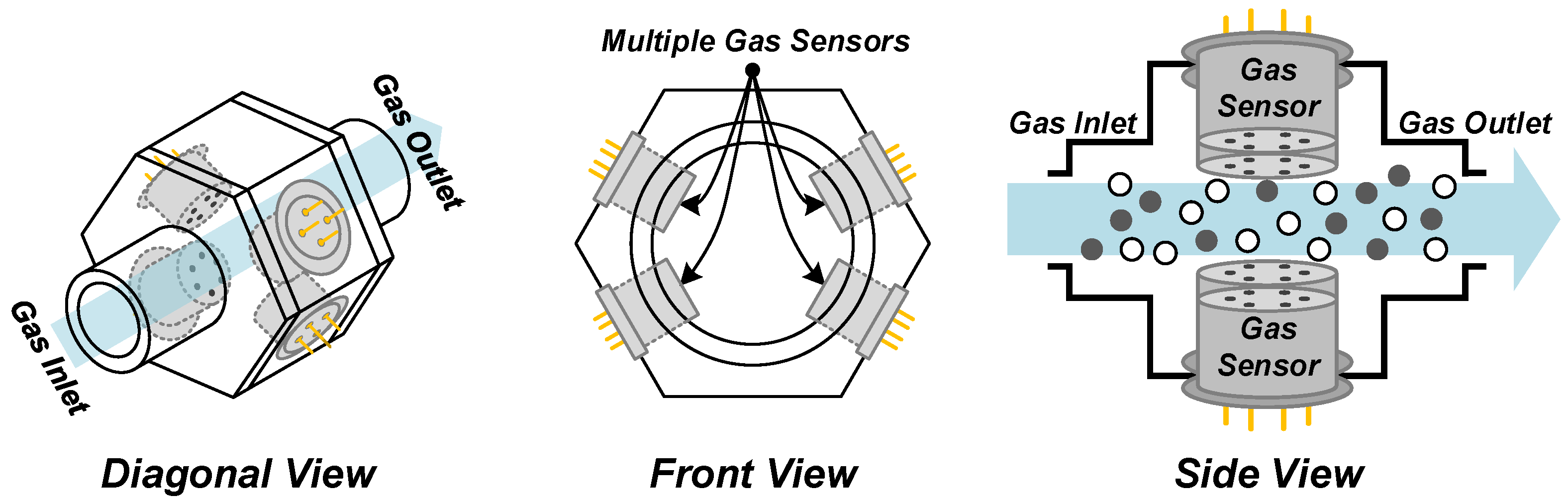
Figure 1 offers the composite view of a multi-gas sensor array structure, a critical component in fields like electronic noses (E-noses), odor profiling, and the detection of hazardous gases [
26,
27]. This structural design strategically positions multiple gas sensors in an array format to simultaneously harvest and analyze output information from various sensor samples. The goal of this configuration is to augment the selectivity of the sensor system by leveraging the unique detection characteristics of different sensor types, thus producing distinctive data signatures for individual gases.
Figure 1 illustrates three perspectives (diagonal, front, and side views) of the sensor array, which is shaped like a hexagonal column. This design allows for the placement of up to six gas sensor samples within the same chamber, ensuring uniform exposure to controlled levels of temperature, humidity, and gas concentrations. In this study, we focus on employing four identical commercial gas sensor samples (Figaro, TGS-2600 [
28]) to demonstrate the prototype ROIC concept. A notable challenge is the baseline distribution problem inherent in multi-gas sensor array configurations. Each sensor, due to its unique physical characteristics, environmental factors, and positioning within the array, may exhibit individual baseline signals. These differences can distort the data, presenting a hurdle in isolating the sensors’ responses solely attributed to gas exposure. For instance, identical sensor samples exposed to the same gas concentration may yield different outputs due to the baseline distribution issue.
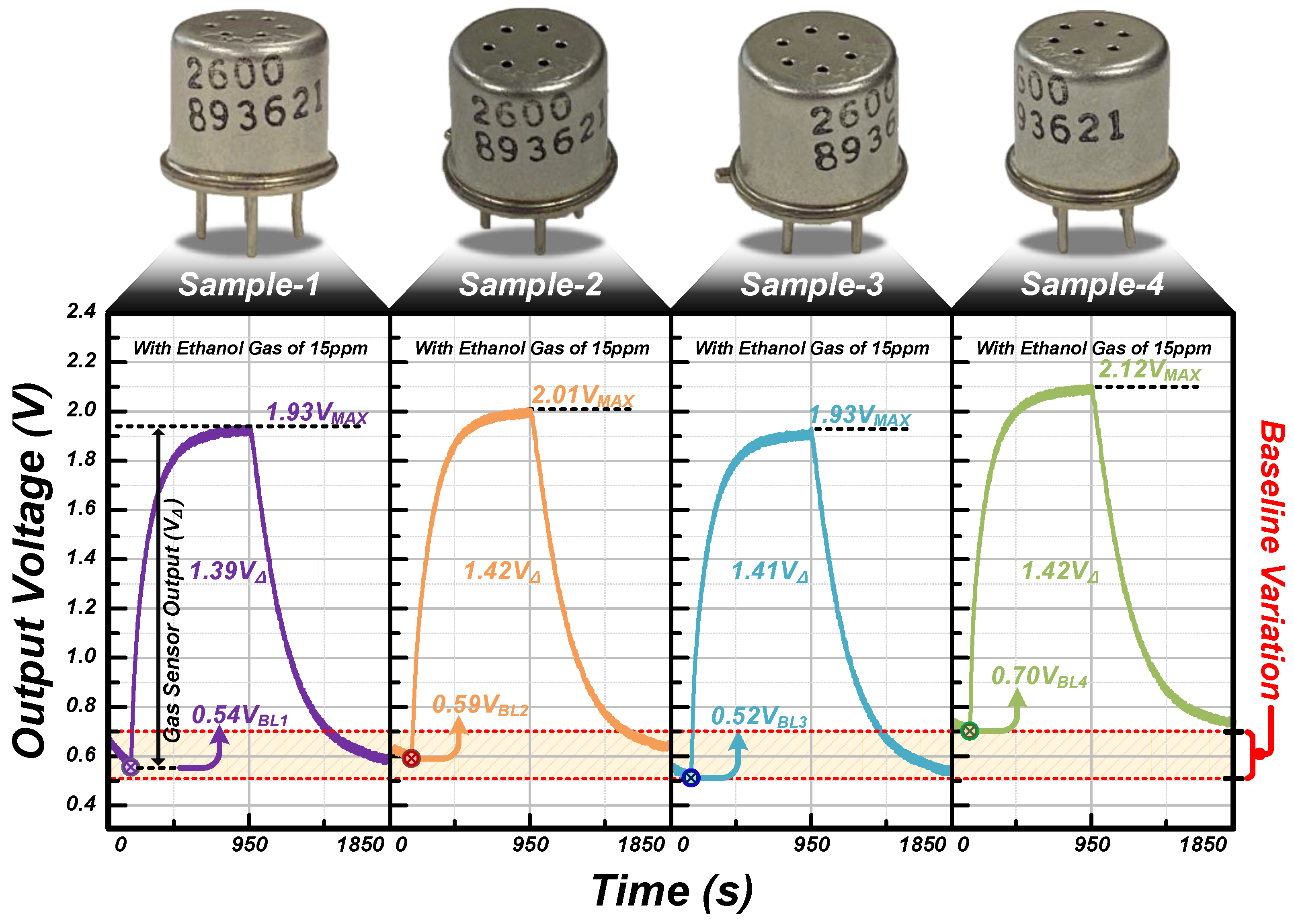
Figure 2 displays the output waveforms from four samples of the same type of gas sensor when measured within the multi-gas sensor array structure depicted in
Figure 1. Each waveform represents output data extracted from one of the four samples, labeled from Sample 1 to Sample 4. Here, V
BL denotes the baseline voltage of the gas sensor output, while V
MAX indicates the maximum output voltage recorded in response to the target gas, which is ethanol for this measurement. The measurement conditions were consistent across samples. An ethanol concentration of 15 ppm was exposed at an airflow rate of 500 sccm, with an average temperature of 22 °C and average humidity of 45%. The gas was injected for a duration of 900 s, followed by air injection for another 900 s, in a repeated cycle. The results reveal notable differences in the baseline and peak output values among the samples, despite the identical testing setup. Sample 1, for instance, shows a baseline of 0.54 V
BL and reaches a peak of 1.93 V
MAX, resulting in a voltage change of 1.39 V
∆. Sample 2 starts at a slightly higher baseline of 0.59 V
BL and peaks at 2.01 V
MAX, with 1.42 V
∆. Similarly, Sample 3′s baseline is 0.52 V
BL with a peak at 1.93 V
MAX, with 1.41 V
∆, and Sample 4 exhibits a baseline of 0.7 V
BL with a peak at 2.12 V
MAX, with 1.42 V
∆. Despite the consistent testing environment and conditions, the sensors exhibited varying V
BL and V
MAX, with a similar V
∆ across the samples. The difference in V
∆ between each sample can be attributed to variations in sensitivity, and it becomes more apparent when distinguishing this from the baseline variation issue. Such differences, even under controlled conditions, emphasize the complexity of achieving uniformity in gas-sensing systems. Additionally, the variability of the baseline indicates the presence of sensor-specific characteristics and environmental factors that contribute to the inconsistency in output values. Addressing the baseline variability is crucial, as it necessitates post-processing digital correction steps, which, in turn, can introduce performance limitations into the gas sensor system. This correction is essential to minimize the baseline scatter and ensure accurate gas detection, reinforcing the need for advanced calibration methods in gas sensor system design to achieve high sensitivity and reliability without compromising the system’s efficiency.
3. The Proposed ROIC with a Baseline Calibration Scheme
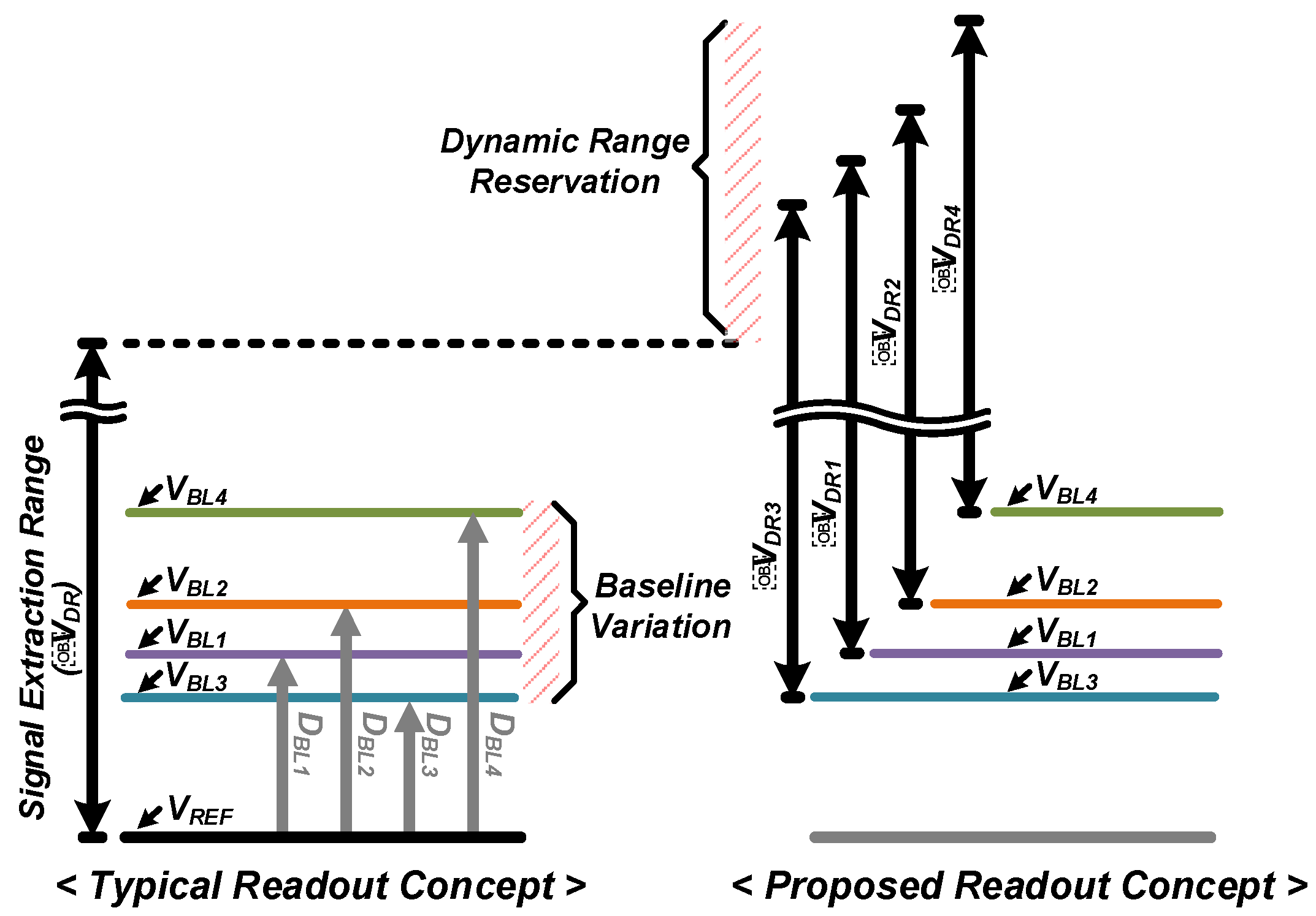
Figure 3 illustrates the distinction between traditional and proposed signal readout approaches for the multi-gas sensor array system. The traditional ROIC readout approach, depicted on the left side of the figure, extracts the electrical signals produced by the input gas within an absolute signal extraction range (∆V
DR). This method is susceptible to baseline variation, impacting the accuracy of gas detection. In the typical multi-sensor array setting, gas sensor samples output baselines ranging from V
BL1 to V
BL4. To ensure reliable signal extraction, the ROIC must accommodate this range and differentiate between the baseline output values (D
BL1 to D
BL4) and the actual gas response in the digital output code through post-processing. This not only leads to a loss of DR but also incurs energy consumption each time the baseline values are outputted and subsequently nullified, a drawback that becomes more pronounced as the array size increases. To mitigate these technical issues, this work introduces a baseline calibration scheme tailored for the multi-gas sensor array. This scheme involves storing the baseline extracted from each gas sensor sample and dynamically regenerating the signal extraction range based on this stored baseline during ROIC operation. In contrast to the fixed ∆V
DR of the conventional ROIC, the proposed scheme adapts the DR to each gas sample’s baseline characteristics, forming distinct DRs from ∆V
DR1 to ∆V
DR4 as needed. This method effectively utilizes the full DR of the ROIC and enables real-time signal extraction without the need for additional post-processing to eliminate the baseline. This approach not only enhances the efficiency of signal processing but also conserves energy by obviating the repetitive task of baseline nullification, thus addressing a crucial energy loss issue in larger arrays.
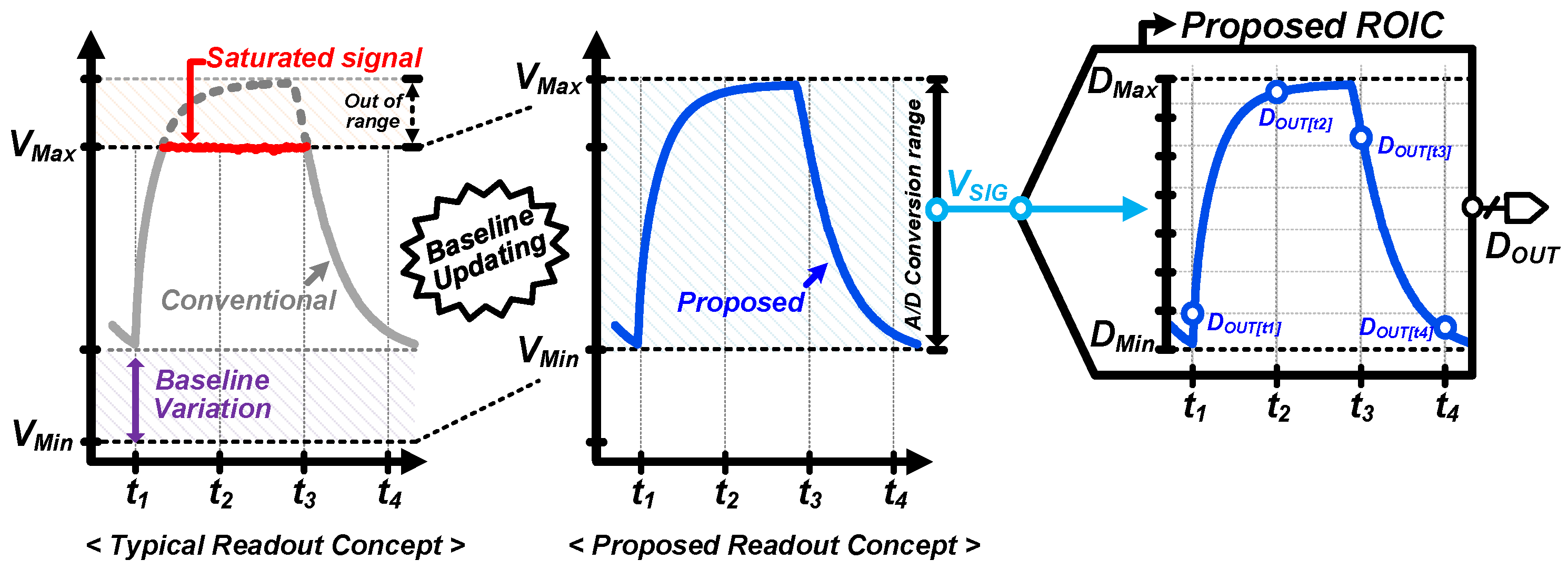
Figure 4 illustrates a comparison between the signal readout capabilities of the traditional ROIC and the proposed ROIC equipped with the baseline calibration scheme. The traditional approach on the left demonstrates how rapid environmental changes can cause the baseline to scatter beyond the signal extraction range of the ROIC, leading to the potential for signal loss, indicated by the “Saturated signal” area. It highlights the vulnerability of the gas sensor to extreme environmental changes. On the right, the proposed ROIC design with the baseline calibration shows an adaptive technique that dynamically updates the baseline in response to environmental fluctuations, maintaining the sensor signal (V
SIG) within the analog-to-digital (A/D) conversion range. This adaptive range adjustment ensures the full sensor response is captured without loss, even with significant variations in temperature and humidity that can affect sensor sensitivity. Then, the digital output (D
OUT) varies linearly with the V
SIG, adjusting as the baseline shifts to accommodate the entire signal curve within the conversion range from D
Min to D
Max. This continuous adjustment ensures that each time point from t
1 to t
4 is captured accurately, reflecting the actual sensor response without any truncation or distortion. In this manner, by periodically updating the baseline, the proposed ROIC can create an appropriate signal extraction range that accommodates these shifts, thus preserving the integrity of signal capture. Thus, the proposed scheme is essential for realizing the full potential of multi-gas sensor array structures, as they allow for more accurate and reliable monitoring and detection capabilities, particularly in complex scenarios where multiple gases are present and precise identification is paramount.
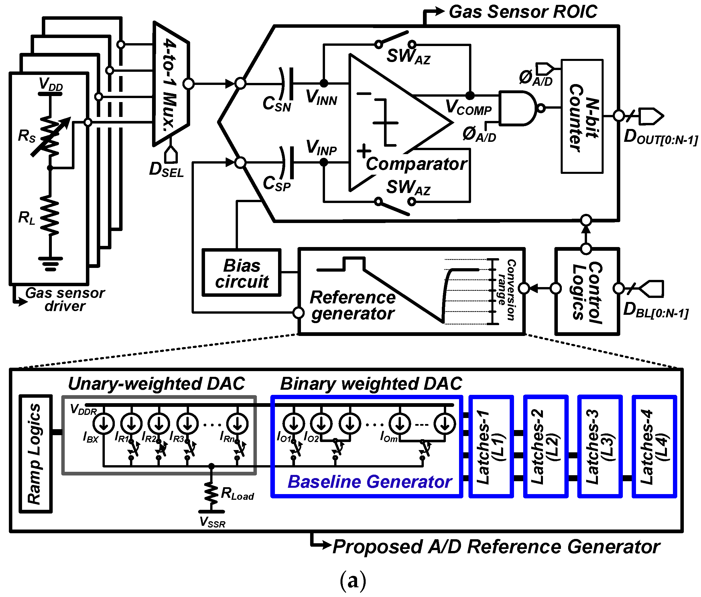
Figure 5 presents the simplified schematic of the proposed ROIC designed with the baseline cancellation scheme. The circuit diagram integrates four gas sensor driving circuits from the multi-gas sensor array, the ROIC with a proposed A/D reference, a biasing circuit for current supply, and control logic for synchronizing operations. The proposed ROIC is based on a typical single-slope (SS) analog-to-digital converter (ADC) architecture [
29,
30], which includes AC coupling capacitors, control switches, a comparator, an A/D reference generator, and an N-bit counter for digital conversion, with N denoting the ADC’s bit resolution. The gas sensor’s driving circuit outputs a voltage reflecting resistance changes due to gas exposure, thus indicating gas concentration levels. A key feature of this ROIC is the integration of a baseline calibration scheme within the A/D reference [
31]. This scheme reads and adjusts the gas sensor’s output voltage to eliminate baseline drift before A/D conversion. As a result, the SS ADC processes only the true sensor response, excluding baseline noise, and converts this into an accurate digital representation. The control logic orchestrates the timing of ethanol and fresh air injections, ensuring that the gas exposure and sensor refreshment are well-coordinated. Additionally, the bias circuit generates the necessary currents to maintain the functionality of the entire system.
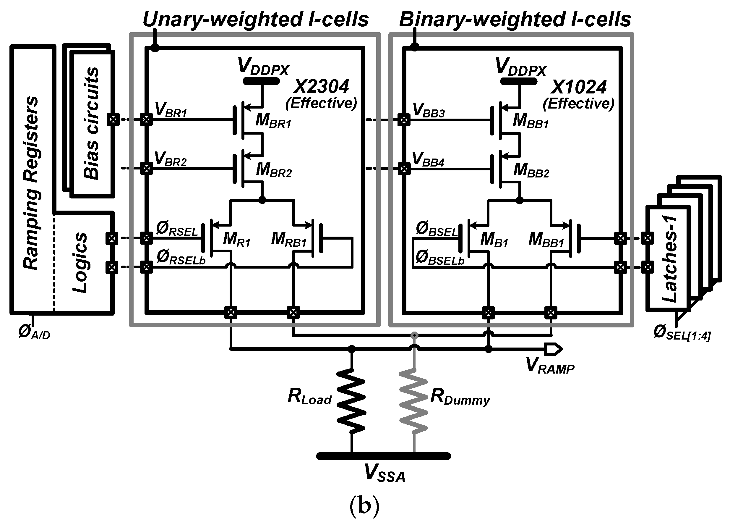
Figure 5b shows the proposed A/D reference generator utilizing a conventional current-steering digital-to-analog converter (DAC) framework [
32,
33]. It comprises unary-weighted current cells (I-cells) and binary-weighted I-cells, four latches, along with load resistors and peripheral components. Additionally, four latches were added to store the D
BL value for each gas sensor in the multi-gas sensor array. The unary-weighted cells produce a ramp voltage (∆V
RAMP) for the SS ADC, while the binary-weighted cells establish a baseline level corresponding to the V
BL. Unary-weighted I-cells are tasked with producing V
RAMP = I
CELL × R
Load) [
31] for the SS A/D conversion by sequentially applying current from the I-cells to the load resistor, R
Load. On the other hand, binary-weighted I-cells are responsible for creating V
BLs. This V
BL is reconstructed from the binary-weighted cells and added to the ∆V
RAMP, thus updating the starting point of the A/D conversion for each sensor sample. To achieve the desired functionality, the A/D reference generator incorporates 3328 I-cells. This total includes 256 I-cells allocated for the pre-emphasis phase, 2048 I-cells to achieve an 11-bit ADC resolution, and an additional 1024 I-cells to adequately compensate for the baseline variation. This mechanism effectively compensates for the baseline, enhancing the precision of the gas-sensing system. Note that, given the undisclosed noise performance of the targeted gas sensor (TGS2600, Figaro), this study addressed the issue by implementing a guaranteed 11-bit resolution noise requirement. This measure ensures that the proposed ROIC does not constrain the noise performance.
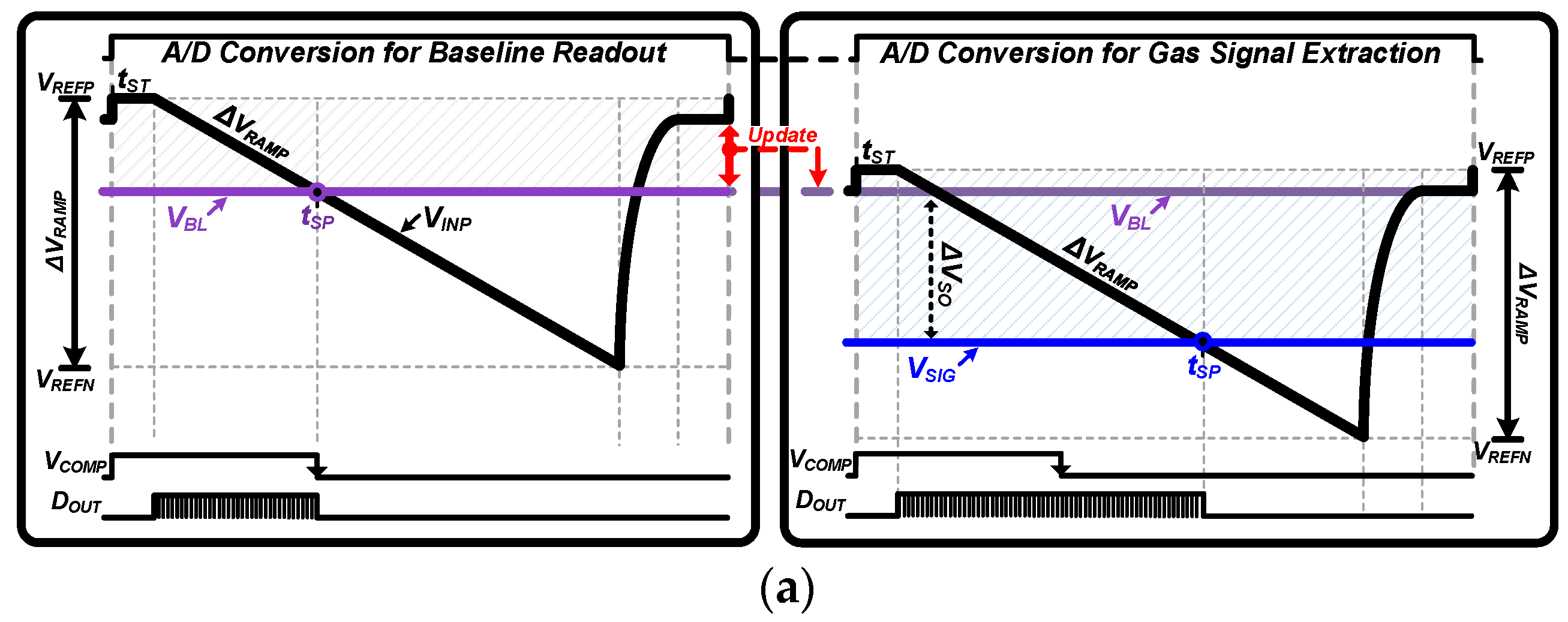
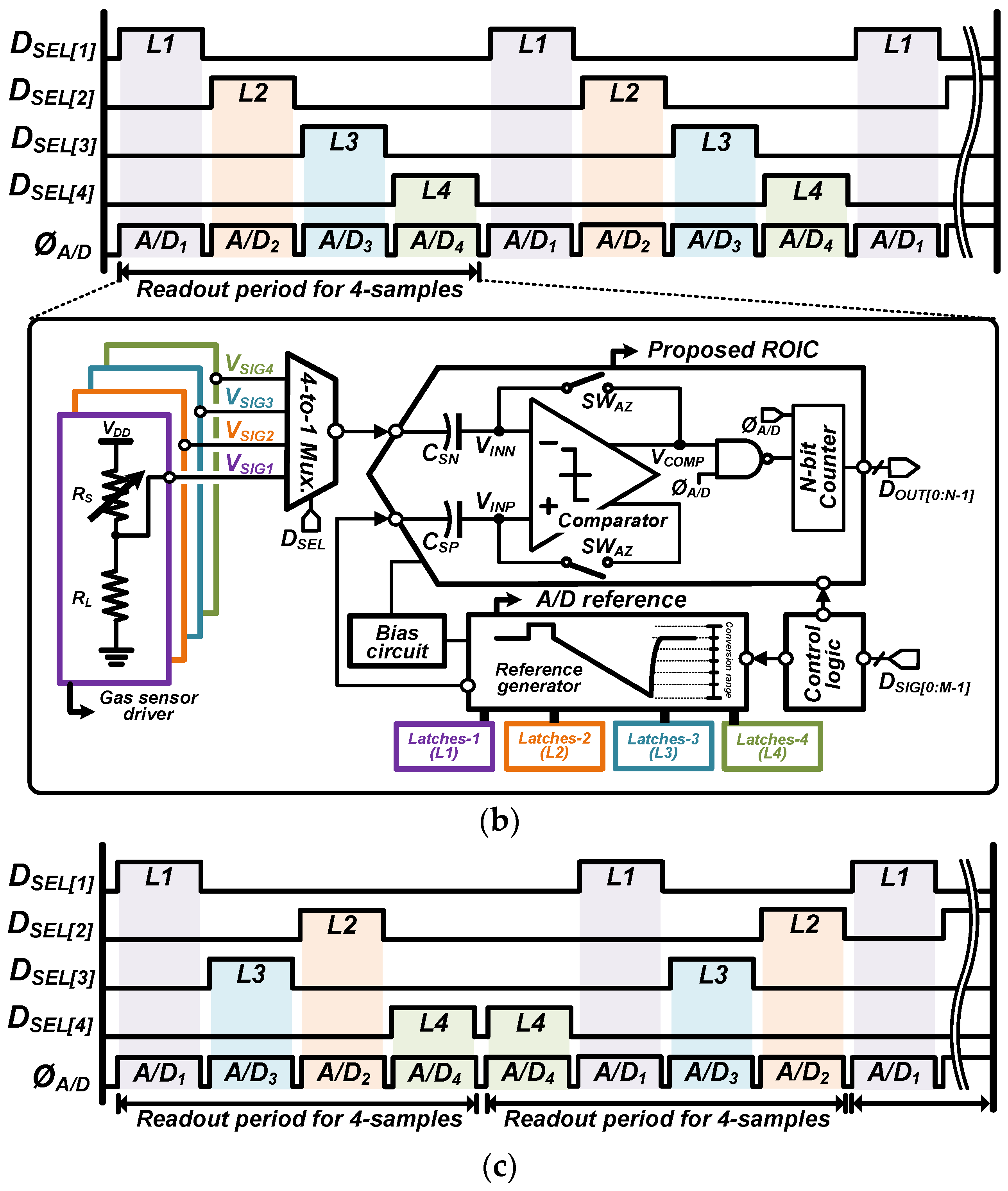
Figure 6 provides a two-part depiction of the timing and operational sequence for the proposed ROIC and its application in a multi-gas sensor array.
Figure 6a shows the simplified operational timing diagram for the proposed ROIC. It outlines two critical periods: the baseline cancellation period and the gas signal readout period. Initially, during the baseline cancellation phase, the ROIC operates similarly to existing SS ADCs, reading the baseline voltage (V
BL) from the sensors. The result of this readout, the digital baseline (D
BL), is then set as the new starting point for subsequent A/D conversions. This process effectively compensates for any sensor offset, ensuring that only the true sensor signal is processed in the following gas signal readout period.
Figure 6b depicts the sequencing for reading out signals from individual sensors in the multi-gas sensor array. This study utilizes four identical gas sensors to demonstrate the efficacy of the baseline calibration scheme. The baselines for each sensor are stored in four separate latches, labeled L1 to L4. These latches are coordinated with a 4-to-1 multiplexer (mux.), which activates the correct baseline for the sensor being read out at any given time. This synchronization ensures that each sensor is activated in turn, with its baseline value ready for calibration against the real-time sensor reading.
Figure 6c shows details of the operational timing for arbitrarily selecting among four gas sensor samples, demonstrating the versatility of our system. It allows for selective extraction of gas samples as needed in any case. It is capable of selectively engaging specific gas samples and their corresponding output nodes through the use of 4-to-1 MUX and digital select (D
SEL) signals. This systematic approach allows for precise sensor output calibration, vital for the multi-gas sensor array’s overall accuracy and reliability in various detection scenarios.
4. Measurement Results and Discussion
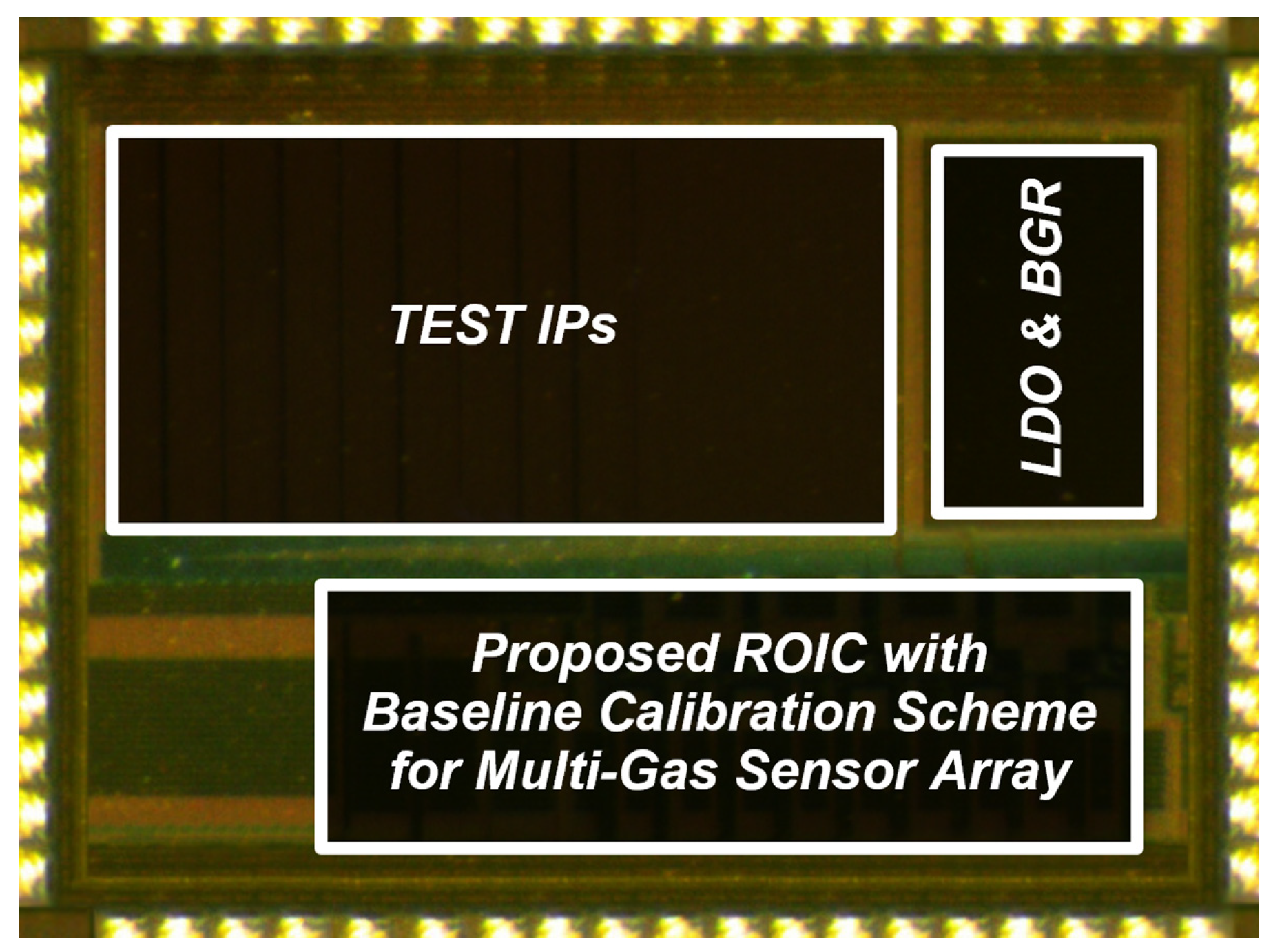
Figure 7 presents the chip microphotograph implementing the prototype ROIC at the silicon level. This silicon prototype was manufactured using a 180 nm standard CMOS process with 1 Polysilicon and 6 Metal layers (1P6M), which was occupied within an area of 3 mm by 2 mm. The prototype boasts a low total power consumption of only 0.43 mW while performing readout operations at a rate of 50 kilo-samples per second (kSPS). The maximum integral non-linearity (INL) normalized in dB with the full-scale value was −75.71 dB, which is effectively 11-bit linearity. In this work, the efficacy of the proposed scheme was verified using Figaro TGS-2600. The ROIC targets a sensitivity range from 0.54 to 0.23 for gas concentrations ranging from 5 ppm to 20 ppm, and a resolution of 39Ω for sensor resistance range from 10 kΩ to 90 kΩ. Here, the sensitivity of the gas sensor is expressed as the ratio of Rs (resistance value of the gas sensor at various concentrations) to Rs (resistance value of the gas sensor in air). The resolution represents the resistance value equivalent to 1 least significant bit (LSB) of an 11-bit resolution ROIC.
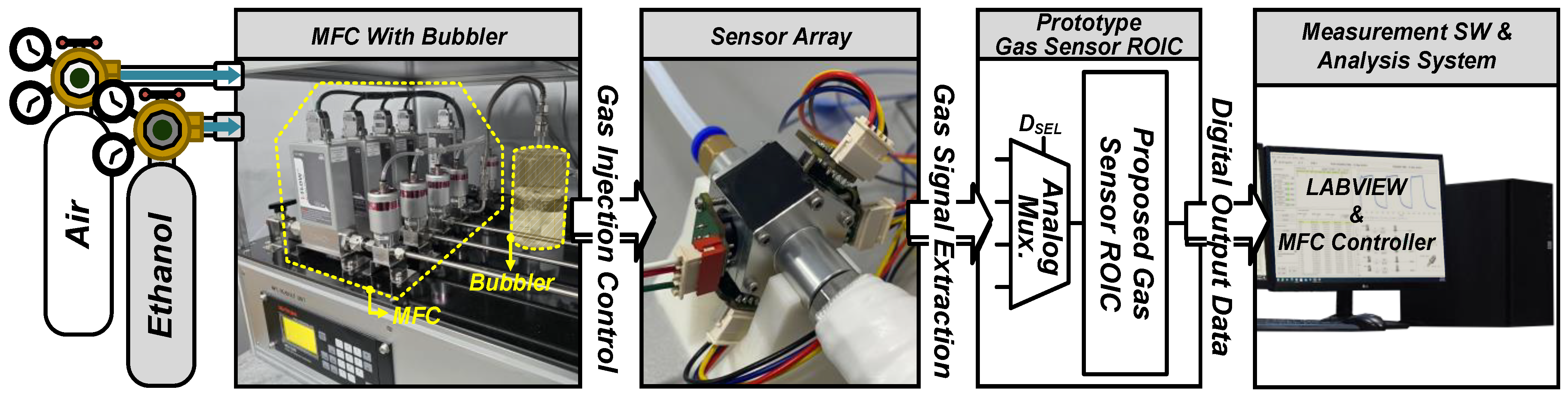
Figure 8 shows the setup for the system-level feasibility testing of ethanol (C
2H
6O) gas sensing. The setup includes several key components: a mass flow controller (MFC); FACTOR I-300, which precisely controls the gas flow; a bubbler capable of humidity regulation; and a multi-gas sensor array chamber equipped with four Figaro TGS2600 sensors (with the capacity to house up to six sensors). Fresh air and C
2H
6O gas are introduced into the system, where the flow rate of C
2H
6O gas is maintained at 150 sccm at a concentration of 15 ppm, with an injection time of 900 s. The sensor measurements are conducted at a normal ambient temperature of approximately 22 °C (±2 °C) and a relative humidity (RH) of 45% (±0.5%) in fresh air conditions. The sensors operate with a load resistance (R
L) of approximately 10 kΩ. The testing protocol includes three detection cycles over a total duration of 7700 s. Data from the sensors are collected and processed by an evaluation board, which interfaces with a computer via USB, transmitting the output digital codes. The results are displayed on a PC screen in real time. Customized MATLAB software with a range of verification functions supports the data analysis, enhancing the test’s efficacy and allowing for detailed scrutiny of the sensor array’s performance in detecting ethanol gas within the test environment.
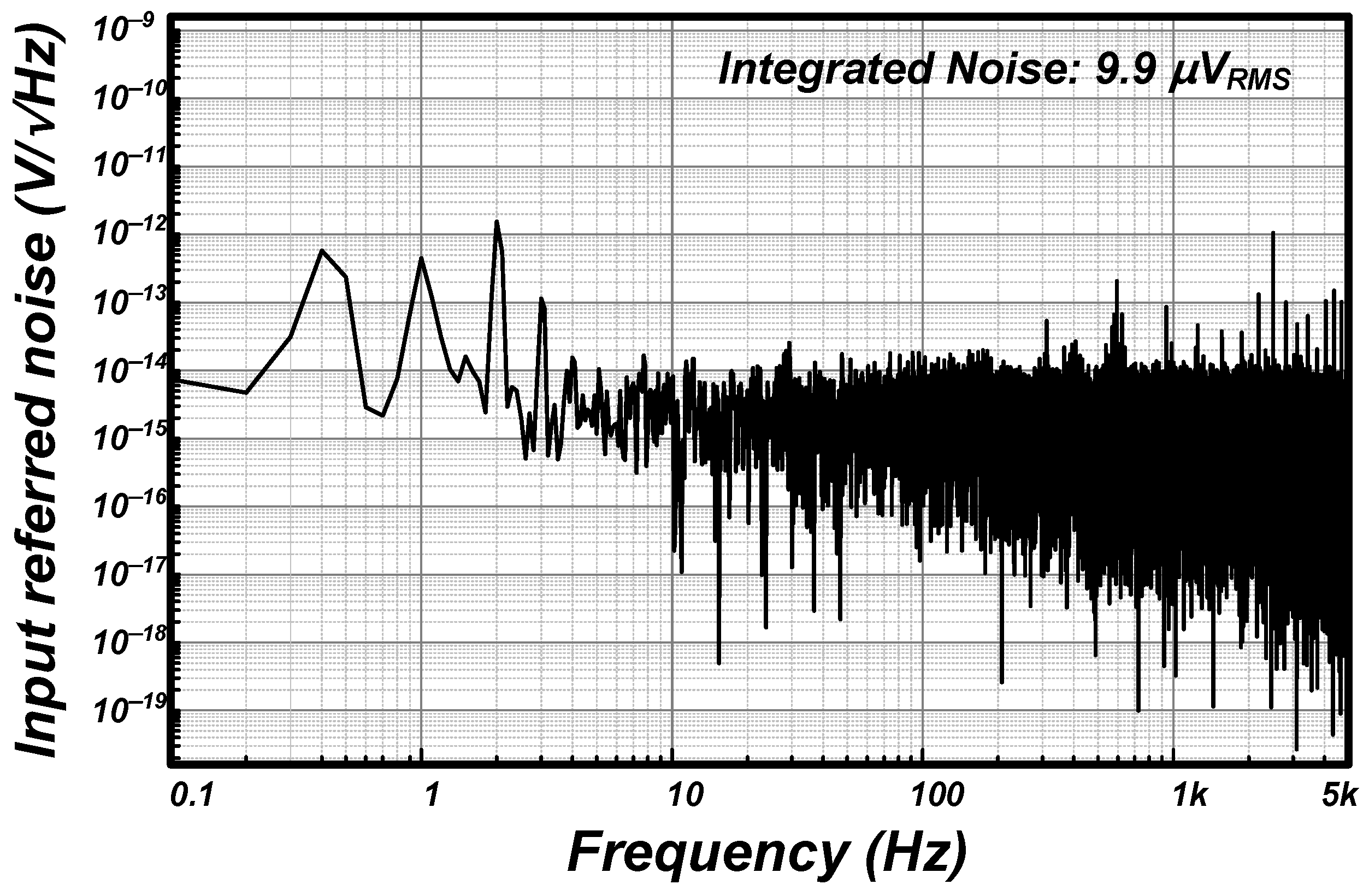
Figure 9 presents the input-referred noise spectrum for the proposed ROIC. This measurement assesses the noise emanating from the output stage of the ROIC and normalizes it by the gain of the circuit to obtain the spectrum. The graph indicates an integrated noise level of 9.9 μV
RMS within a frequency range of 0.1 Hz to 5 kHz, which is a measure of the circuit’s noise performance over a defined bandwidth and provides insight into the signal quality that the ROIC can maintain. To fairly compare our findings with state-of-the-art research [
34,
35], we converted our noise figure to a current figure based on a 9 kΩ input resistance, resulting in 1.1 nA
RMS. A study by [
34] achieved 27.5 pA
RMS, and [
35] reported 613.7 nA
RMS, placing our performance at a moderate level. However, our study’s focus extends beyond noise reduction, emphasizing the ROIC technique that facilitates real-time baseline calibration in multi-gas sensor arrays without additional digital post-processing, marking a notable advancement in the field.
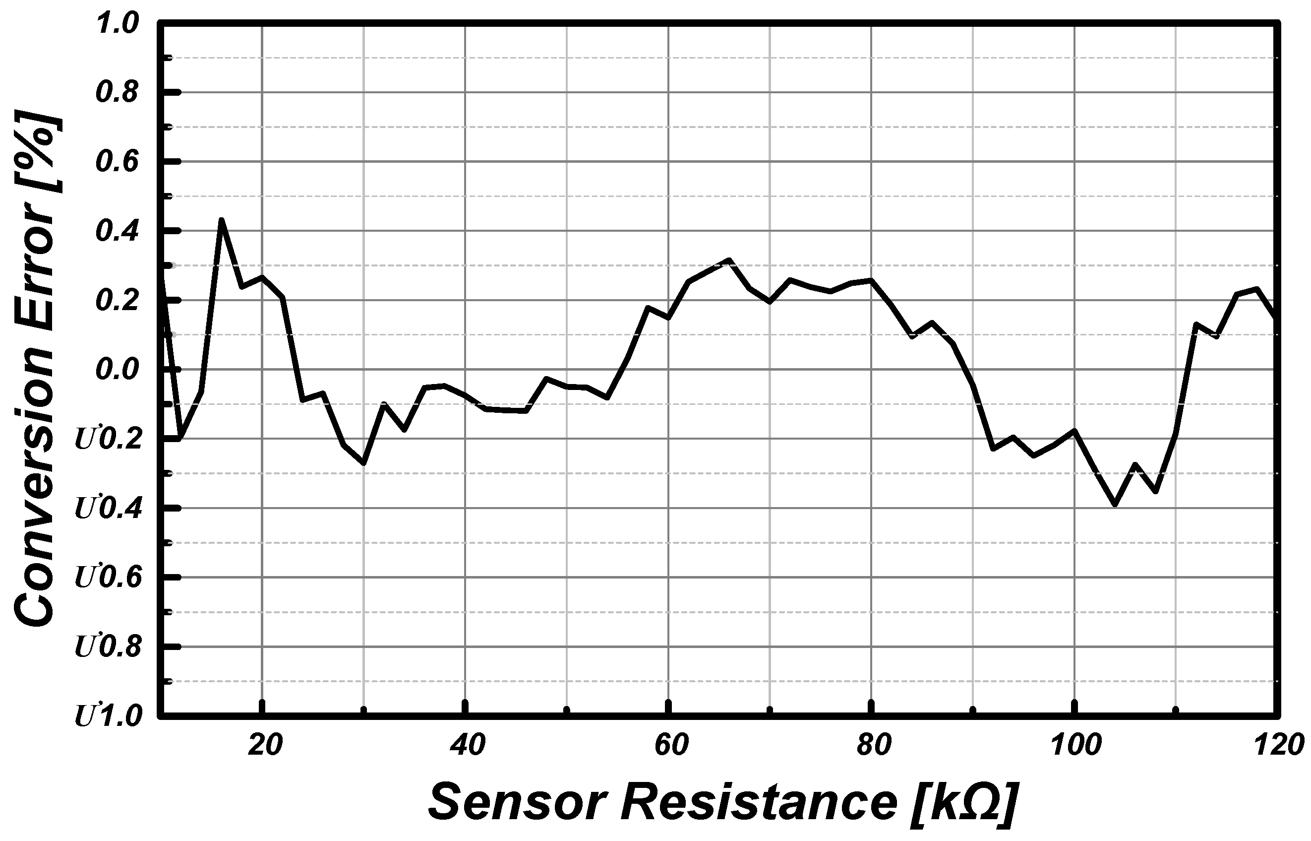
Figure 10 provides a conversion error plot over the sensor’s resistance range, a crucial indicator of the ROIC’s precision. Conversion error in the gas sensor ROIC refers to inaccuracies that occur when translating the gas concentration measured by the sensor into an electrical signal, either voltage or current. This error predominantly arises within the ROIC’s conversion circuitry, where the sensor-generated signal is measured and processed. The resistance ranges from 10 to 120 kΩ were tested to mimic the sensor’s response to an actual gas, as specified in the datasheet of the Figaro TGS2600 gas sensor. The plot shows that the proposed ROIC maintained a conversion error below 0.45% throughout the tested resistance range. Compared to [
26], which reported a conversion error of less than 0.8%, our study’s lower error rate highlights the efficacy of our ROIC in generating precise digital outputs from the sensor’s analog signals. This low error percentage signifies the ROIC’s capability to produce accurate digital outputs from the sensor’s analog signals, confirming the circuit’s effectiveness in preserving the fidelity of sensor data across the specified resistance spectrum.
Table 1 presents the summary of performance metrics.
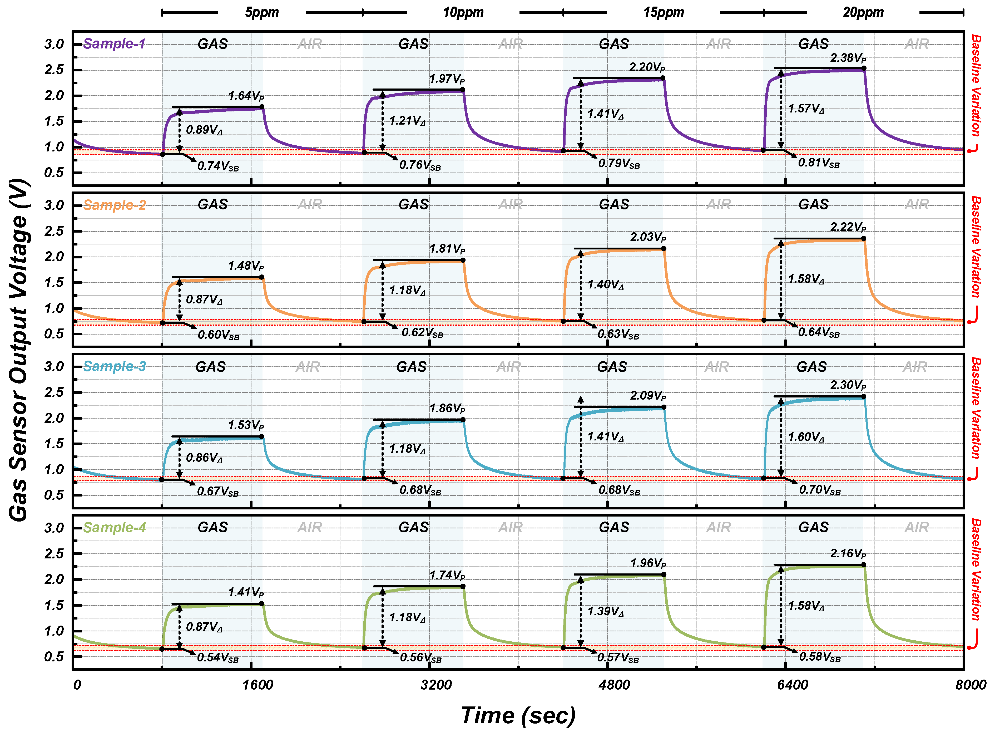
Figure 11 illustrates the output waveforms from individual sensor samples within a multi-gas sensor array connected to the conventional ROIC. The experiment, conducted over 8000 s, began with an 800 s fresh air injection to stabilize sensor operation and enhance data reliability under controlled conditions at an average temperature of 22 °C (±2 °C) and an average relative humidity of 45.1% (±0.5%). The procedure involved alternating injections of ethanol gas and fresh air into the chamber at concentrations of 5 ppm, 10 ppm, 15 ppm, and 20 ppm, with ethanol gas mixtures adjusted to the respective concentrations by varying the flow rates of ethanol and fresh air for 900 s, followed by a 900 s fresh air flush at 500 sccm. Despite the uniform concentration changes applied to each sample, maximum output values (V
MAXs) were dispersed due to varying baseline voltages (V
BLs), indicating that baseline voltage increases with each subsequent fresh air injection. This inconsistency highlights the limitations of the traditional ROIC in managing baseline variability among sensor outputs, necessitating digital correction to ensure reliable output data. On the other hand,
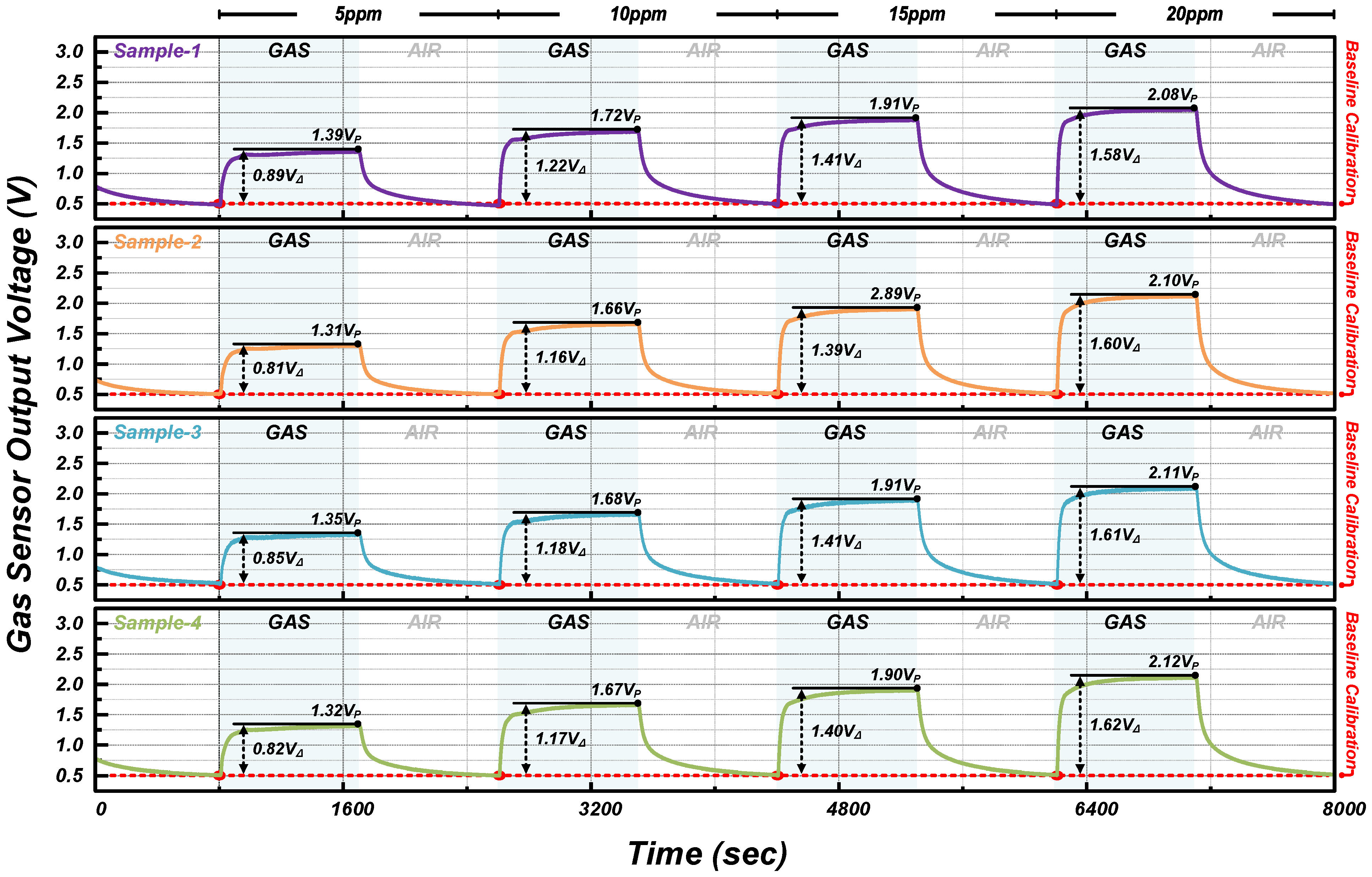
Figure 12 provides the measurement results for the multi-gas sensor array using the proposed ROIC, emphasizing the baseline calibration for each sensor sample. Unlike the conventional approach, where the baseline voltage distribution spanned a 368 LSB range at an 11-bit A/D resolution, the proposed ROIC demonstrated a constrained baseline voltage distribution within 1 LSB, with a consistent starting point for A/D conversion defined at 0.5 V, thus preserving the dynamic range (DR). This distinction underlines the effectiveness of the proposed ROIC in maintaining uniformity across sensor readings by directly compensating for baseline drift, showcasing its potential to enhance gas sensor array performance without the need for extensive post-processing. This means that the proposed ROIC can obtain more reliable and precise sensor outputs, confirming its substantial improvement over traditional ROICs. Furthermore, the capability of the proposed ROIC to periodically update the V
BL values for each gas sensor means that the system can dynamically adjust to varying measurement environments or conditions, thereby minimizing potential impacts on the sensor’s accuracy. The primary advantage of using the proposed scheme lies in its ability to apply baseline compensation directly and efficiently, without the overhead of data-intensive processing or the need for advanced analytics platforms. Therefore, the proposed ROIC is validated as one of the robust solutions for advanced gas-sensing applications.


