Article

Flow Physics of Profile Control Fluids in Porous Media and Implications for Enhanced Oil Recovery: A Microfluidic Study

1
State Key Laboratory of Petroleum Resources and Prospecting, China University of Petroleum, Beijing 102249, China
2
SINOPEC Northwest China Petroleum Bureau, Urumqi 830011, China
*
Author to whom correspondence should be addressed.
Processes 2022, 10(1), 112; https://doi.org/10.3390/pr10010112
Submission received: 30 November 2021 / Revised: 22 December 2021 / Accepted: 23 December 2021 / Published: 6 January 2022
(This article belongs to the Special Issue Two-Phase Flow Heat Transfer: Design, Simulation and Optimization)

Abstract

:
Novel profile control agents are constantly emerging in the field of enhanced oil recovery, contributing to the extension of a stable production period. However, evaluation performed through conventional core flow experiments is usually inadequate to reveal the in-depth mechanism of profile control agents. Besides, due to different operation and production modes, there is an urgent need for a specific experimental method applicable to horizontal wells in bottom water reservoirs. In this context, this paper describes two models tailored to bottom water reservoirs and investigates the flow characteristics and mechanisms of three water-shutoff agent types. At the pore scale, further study was carried out on the water-shutoff synergism between a gel and an emulsifier. The results show that the gel is present at the edge of the pore body, while the emulsion is blocked in the center of the pore body. Hence, gel that enters a water channel (main flow and accumulation area of emulsion) can cooperate with an emulsion to achieve high-strength water shutoff, making the bottom water that re-invades mainly break through at oil-rich areas. Compared with water shutoff with gel alone (randomly distributed in the breakthrough area), the synergism improves the gel’s ability to select flow channels, inhibits emulsifier channeling, and achieves a remarkable EOR effect.

1. Introduction

Bottom water reservoirs exist widely in oilfields, mostly developed through horizontal wells. Compared with vertical wells, smaller production pressure difference in horizontal wells helps restrain the bottom water coning and increase production [1]. After years of development, most horizontal wells will enter the high water cut stage, and water shutoff operation is necessary to further improve the recovery [2,3,4,5]. This article mainly focuses on water plugging agents used in horizontal wells of bottom water reservoirs.
At present, four types are recognized as agents for water plugging in horizontal wells: (1) a polymer gel system, (2) a surfactant, (3) a precipitate, and (4) a disperse system [6]. The primary components of polymer gels are polymer monomers and functional monomers; the long-chain polymer is cross-linked into a spatial network structure in formation with a cross-linking agent to block the channel. Polymer gel systems are commonly used in oilfields because of their low cost and simple technology. Scholars have carried out a large number of systematic studies on polymer gel and managed to control the strength of underground gel formation by polymer concentration and crosslinking agent concentration [7,8]. Liang et al. used core flooding experiments coupled with NMR scans to clarify the gel-dehydration mechanism [9]. Seright et al. designed a gel-injection parameter that could be used for water-shutoff treatment in fractured reservoirs through analytical methods [10,11].
Disperse systems are another widely applied plugging agent in oilfields, represented by polymer microspheres (particle gel). A stabilizer is used to help dispersed substances such as particles form a relatively stable suspension in water, then dispersed substances are readily injected into the formation to block large pores in the channeling zone [12,13]. Bai et al. proposed a preformed particle gel (PPG) to achieve profile control of heterogeneous and fractured reservoirs [14,15]. A series of test tube experiments and core experiments were performed to carry out systematic research on PPG, and a numerical simulation method for the characterization of PPG action mechanism was established, which paved the way for its field application.
Precipitation occurs in chemical reactions between an injected fluid and original components underground. This type of plugging agent is represented by sodium silicate and is relatively expensive. It is mainly used in salt-rich reservoirs with high Ca2+ and Mg2+. After the sodium silicate solution is injected into the formation, it can form calcium silicate precipitation with Ca2+ in the formation water. The precipitate exists in the form of gel particles and plays a role in blocking water. However, low viscosity (2–10 cp) weakens its profile control effect.
Surfactants emulsify the crude oil in the formation by injecting fluid to form an emulsion, which will squeeze and deform when passing through the pore throats to increase the flow resistance of the water channel [13,14,15]. Surfactants are usually used with a strong gel system to avoid the tendency for channeling [16,17,18,19]. Previous studies show that the current selection and evaluation of plugging agents are primarily based on core displacement experiments, with pressure drop (resistance coefficient, residual resistance coefficient) as the evaluation benchmark. New experimental methods are needed to clarify the flow physics and mechanism of plugging agents in the development of bottom water reservoirs.
The microfluidic model can visually present the fluid flow process in porous media, which provides important support for studying the mechanism of chemical agents to enhance oil recovery [20]. Xu et al. designed microscopic models to study the formation and flow process of an O/W emulsion and confirmed that the O/W emulsion could block the channel and divert the subsequent injection water to low-permeability formations [21,22,23]. Yu et al. used a microscopic model to systematically study the formation mechanism of W/O/W emulsions and the mechanism of enhanced oil recovery [24]. Sendekie and Bacchin designed a microfluidic model to study the mechanism of polymer microspheres to achieve water-shutoff through logging effects [25]. Liang et al. used a microfluidic model to visualize the gel-like plugging agent’s dehydration and gel formation process and pointed out the distribution position of the dehydrated gel in the porous medium [26].
Researchers have also conducted microfluidic experiments to study the mechanisms of blocking agents. Sendekie et al. studied the flow behaviors of polymer nanospheres through a theoretical homogeneous micromodel [26]. They clarified the clogging of pore entrances and the adsorption of PNSs on the rock surface. However, their microfluidic experiments only researched the flow of polymer nanospheres as a single-phase flow. Besides, they only consider the impacts of particle/particle and particle/wall interactions on the retention of PNSs, while failing to take into account the influence of PNSs–oil interaction. Su et al. used a fractured 2.5D micromodel to further research the blocking effects of polymer nanospheres in fractured reservoirs [27]. However, they failed to consider the blocking effects of polymer nanospheres in pores. Moreover, few researchers have focused on understanding the blocking mechanisms of a gel by micromodels.
This paper describes two types of microfluidic models that could simulate the production characteristics of typical bottom water reservoirs in horizontal wells and covers their use in experiments with three types of plugging agents: polymer gels, polymer microsphere dispersions, and emulsifiers. The study of flow characteristics and the mechanism of action is expected to provide a reference for the scientific selection of plugging agents to increase the productivity of horizontal wells in bottom water reservoirs.

2. Methodology

2.1. Chemicals

Kerosene obtained from Aladdin Ltd (Cuddington, UK). was used as the oil phase in this study. Before experiments, the kerosene was dyed by Sudan IV for identification and also filtered through 0.25-mm filter paper. The polymer (Flopaam 3530S) was obtained from SNF (Cedex, France). The crosslinking agent TD-2A was purchased from Xinjiang Baomo Company. The polymer microsphere PCS and emulsifier SC-Z were purchased from Beijing Yide Petroleum Company (Beijing, China).

2.2. Micromodels

The pore structure of sandstone slices scanned by CT was extracted by binarization, and the microscopic model was designed by image stitching. Two types of microfluidic models were produced: one is a homogeneous model simulating a typical homogeneous bottom water reservoir that is completely watered-out; the other is a heterogeneous model simulating a typical heterogeneous bottom water reservoir that is partially watered-out. The model is 2.5 cm in length, 1.5 cm in width, and 20 μm in depth. The average width of the low-permeability channel is 60 μm, and the average width of the high-permeability channel is 180 μm. Two types of microfluidic models are shown in Figure 1.

2.3. Micromodel Flooding Schemes

The experiment process is as follows:
(1) Model cleaning: Before the experiment, the model was repeatedly washed with hydrochloric acid solution, sodium hydroxide solution, ethanol, and deionized water, respectively.
(2) Model saturated with oil: The oil phase was injected into the micromodel by a FLUIGENT pump (MFCS-EZ) at a constant pressure of 100 mbar. To remove all gas bubbles trapped in the micromodel, the injected pressure was increased from 100 mbar to 4000 mbar with a gradient of 300 mbar. In this case, all trapped gas bubbles were gradually compressed and mobilized by the injected-oil phase.
(3) Bottom water invasion: Constant-rate water flooding from the bottom of the model is performed to simulate the process of bottom water invasion. A Harvard pump (PHD UL-TRATM) was used to inject the displacement fluids. The flow rate of the aqueous phase was controlled at 0.1 μL/min (Darcy velocity divided by the void fraction of porous media), equivalent to approximately 2 ft/day, which is a typical flow rate used in the EOR process. The flooding is stopped after the water cut increases to 98% in the outlet.
(4) Plugging agent injection: After water invasion, the plugging agent system is injected at the same speed from the top of the model to simulate the process of water plugging in horizontal wells.
(5) Water reinvasion from the bottom: Step (3) is repeated to simulate the process of water invasion again after the plugging agent is blocked.
In the above process, the flooding in the porous micromodels was observed by a Leica M165FC microscope, and recorded by a Leica CCD camera (100 fps, 1600 × 1200 pixels).

3. Results and Discussion

3.1. Performance Tests of Profile Control Fluids

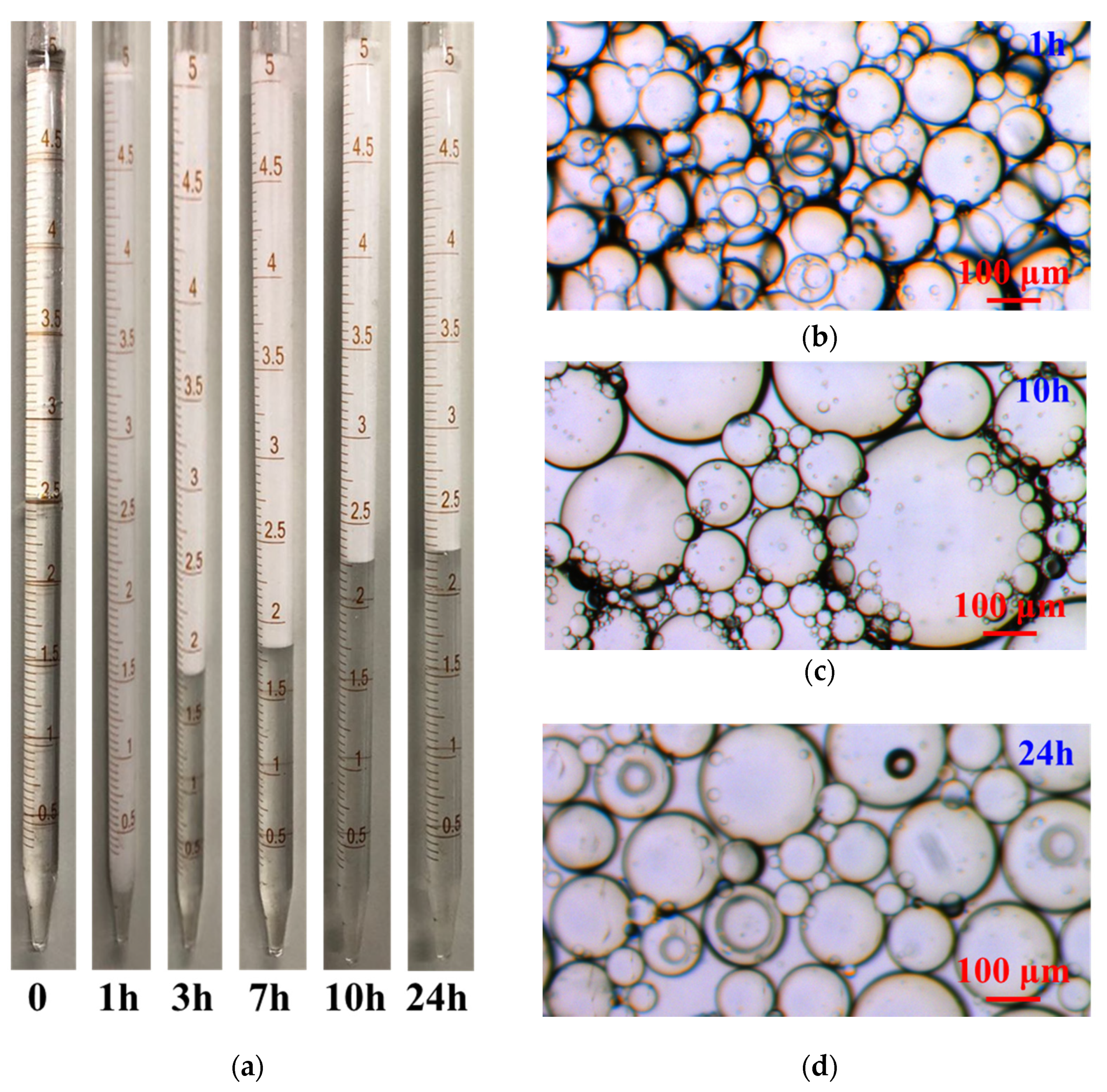
3.1.1. Emulsifier Performance Test

Emulsion-phase behavior tests were conducted to investigate the emulsifying ability. As shown in Figure 2, after mixing the emulsifier and the oil phase at a ratio of 1:1, all of the oil phase was emulsified, and the emulsion gradually shrank during the standing process. The emulsion gradually stabilized after about 10 h, forming tight emulsion blocks on the upper part of the water phase. Figure 2b–d shows the microscopic images of the emulsion at different times, displaying that emulsions of different particle sizes appeared immediately after mixing. As the standing proceeded, the size of most emulsions gradually stabilized at about 100 μm.

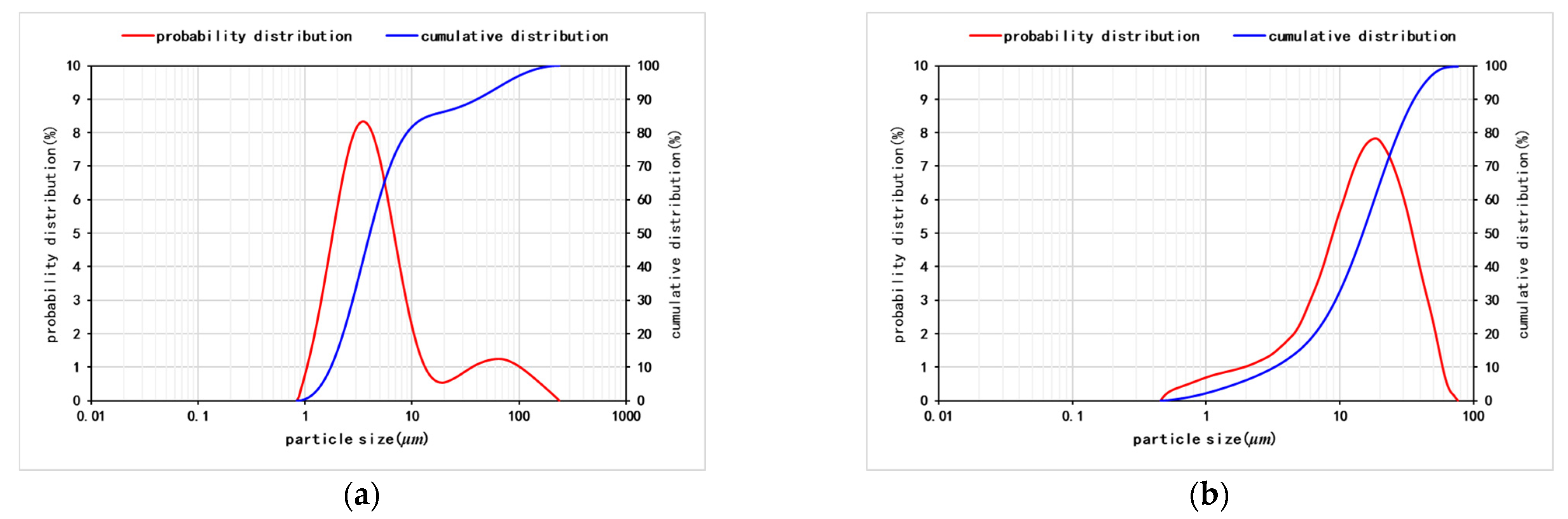
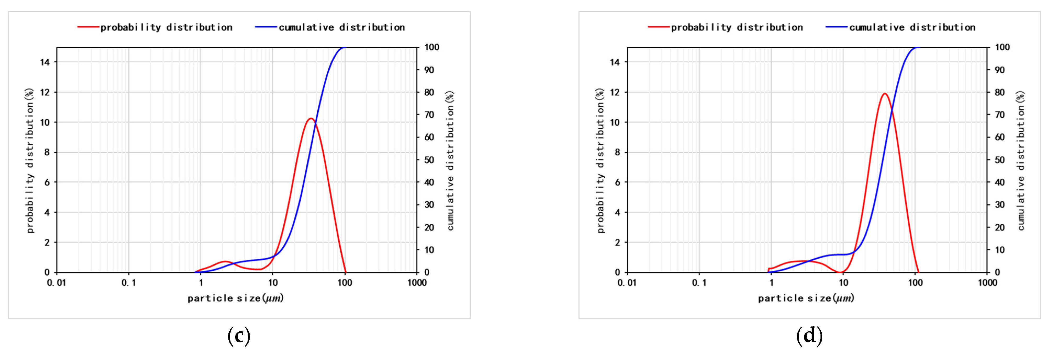
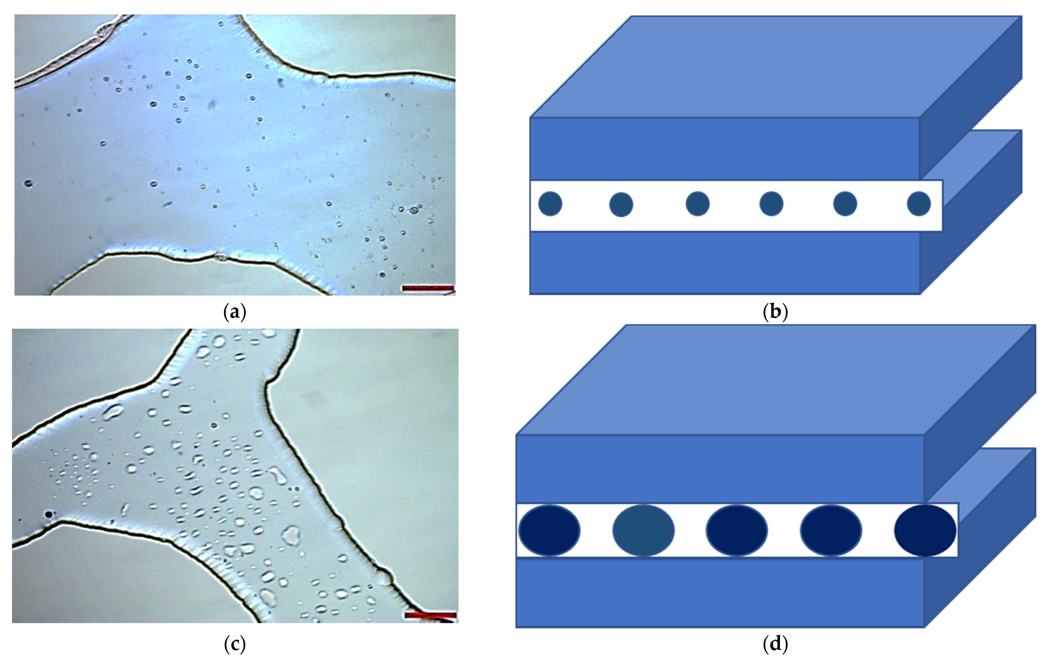
3.1.2. Microsphere Performance Test

The mother liquid of polymer microspheres was diluted with deionized water at 1:100 to prepare 1% polymer microsphere dispersion. The dispersion is stood, and a Top-Sizer laser particle size analyzer is used to measure the particle size of the dispersion during the standing process. The result shows that the average particle size of the newly prepared dispersion was about 3.7 μm (Figure 3a) and that the particle size of the microspheres remained basically unchanged at 32 μm after 3 days of expansion (Figure 3d).

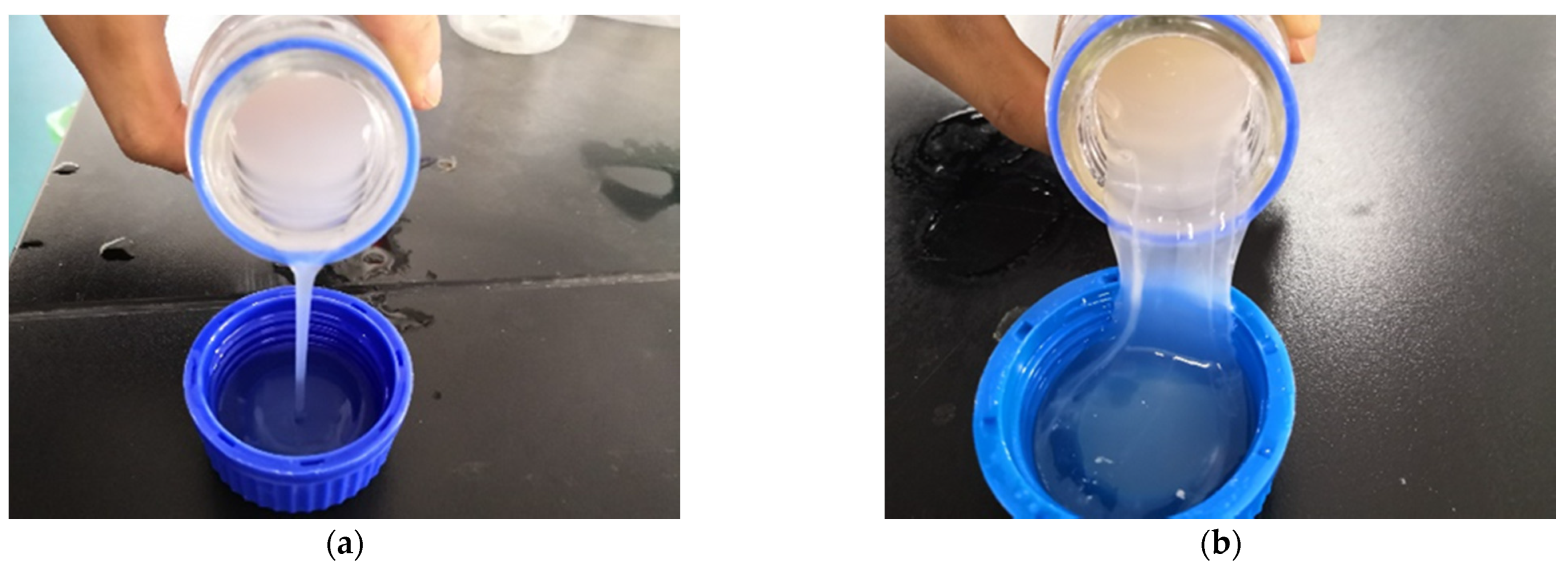
3.1.3. Gel Performance Test

First, a 3000 ppm polymer solution was prepared with deionized water, and its viscosity at 25 °C was measured with a Brookfield DV2T rotating viscometer. Then, the polymer solution was mixed with 0.01% cross-linking agent TD-2A. The experimental results are shown in Figure 4. The fluidity of the mixed liquid before gelation was relatively high, with a viscosity of 60 mPa·s. After 24 h of mixing, the mixture exhibited characteristics of gel, and its viscosity reached 1041 mPa·s.

3.2. Flow Dynamics of Plugging Agents

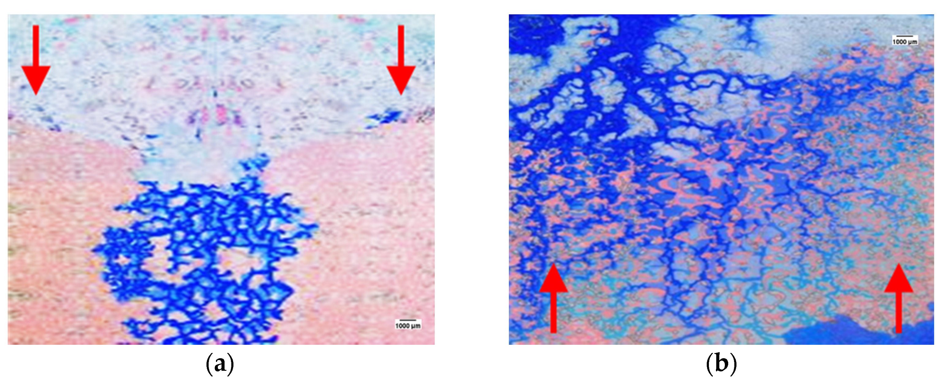
3.2.1. Water Shutoff of Emulsifier

Figure 5 shows the results of an in-depth profile control of microspheres using a homogeneous model. Calculated by the digital processing of the experimental images, the recovery degree increased from 63% to 76%. In the homogeneous model, the invasion front of bottom water was relatively stable, and the bottom water rose uniformly along the bottom of the model. The entire model presented a completely watered-out state. After flooding, the microscopic residual oil had the same occurrence as the state proposed by Li et al., showing the typical characteristics of “overall dispersion and local concentration” [24]. After injecting the emulsifier along the simulated “horizontal wellbore”, since the emulsifier and the water phase are completely miscible, the emulsifier flowed along the channel invaded by the bottom water, and the flooded area changed from dark blue to shallow blue, as shown in Figure 6. However, in the area where the emulsifier flowed, the clustered remaining oil that was locally concentrated was found to be mobilized by the emulsifier and became small dispersed oil droplets. The droplets were carried by the emulsifier and migrated to the deep part of the reservoir during the emulsifier injection. When the bottom water invaded again, droplets would get stuck when flowing through small pore throats, leading to a local detour of the bottom water, and realizing the development of the remaining oil.
Figure 7 shows the results of the heterogeneous model, wherein the recovery increased from 36.9% to 40.1% after the emulsifier blocked water. Most bottom water flowed along the high-permeability area, and consequently oil was left in the low-permeability part on the two sides of the high-permeability area. During the process of emulsifier injection, the emulsifier still flowed along the high-permeability area, and the remaining oil in the low-permeability area remained untouched. In the subsequent water-invasion process of the bottom water, due to the high oil-washing efficiency in the high-permeability area, little oil is emulsified, resulting in a poor microscopic detour effect. The subsequent bottom water still flowed along the high-permeability channel, and the remaining oil in the low-permeability area was basically not influenced.
As shown in Figure 8, the flow physics of an emulsifier as a horizontal well water-shutoff in bottom water reservoirs include the following facts: (1) the emulsifier and the water phase have the same mobility and flow along the water phase channel; (2) in the process of emulsifier injection, through diffusion and disturbance, the oil phase is emulsified to displace the residual oil; (3) as the emulsion flows with the bottom water, it will get stuck when flowing through the pore throats, leading to the detour of the subsequent invasion of bottom water; (4) however, the profile control effect of this emulsion is very limited, and it can only realize the spread and expansion of homogeneous reservoirs at pore scale, which has little effect on heterogeneous reservoirs.

3.2.2. Water Shutoff of the Microsphere

Figure 9 shows the results of the in-depth profile control of microspheres using the homogeneous model. The recovery degree of the homogeneous model increased from 68.9% to 90.1%. As can be seen from the figure, since the microsphere dispersion has the same mobility as the water phase, after the microsphere dispersion was injected, the dispersion mainly flowed along the bottom water invasion channel, and the whole model turned to light blue in the deep blue area of the bottom water invasion. During the injection, the injected fluid diversion was realized by blocking and bridging at the pore throats, then trapped oil was displaced. After 3 days of expansion, in the process of bottom water invasion, the bottom water could no longer fully enter the channels occupied by the microspheres. As shown in the figure, some bottom water flowed around the light blue area. By comparing the microspheres in the light blue channel and the dark blue channel, it can be seen that the microspheres in the light blue channel were squeezed because their diameter was larger than the depth of the channel after expansion. Then the local area of the homogeneous model was blocked, and the microspheres wherein the water phase could enter did not show this feature.
Figure 10 shows the results of the emulsifier water shutoff experiment using the heterogeneous model; the recovery degree increased from 36.1% to 72.1%. Figure 10 shows that, in the heterogeneous model, when the microsphere dispersion was injected, it still flowed mainly along the bottom water invasion channel and left the remaining oil in the low-permeability area unused. But after 3 days of expansion, the microspheres in the high-permeability channel began to exert a good blocking effect; the injected water effectively flowed along the low-permeability channel, and the effective production of the remaining oil in the low-permeability area was realized.
Figure 11 depicts the flow physics of the microsphere dispersion as a horizontal well water shutoff in a bottom water reservoir: (1) the microsphere dispersion has the same mobility as the water phase and flows along the water phase flow channel; while the oil phase in other areas is untouched, especially in heterogeneous reservoirs, the micro-spheres hardly enter the low-permeability area and will not pollute the low-permeability layer; (2) the expanded microspheres can effectively relieve water channeling, causing the re-invasion bottom water to detour, and effectively mobilize the remaining oil in the low-permeability area. The in-depth profile control effect is remarkable in heterogeneous reservoirs.

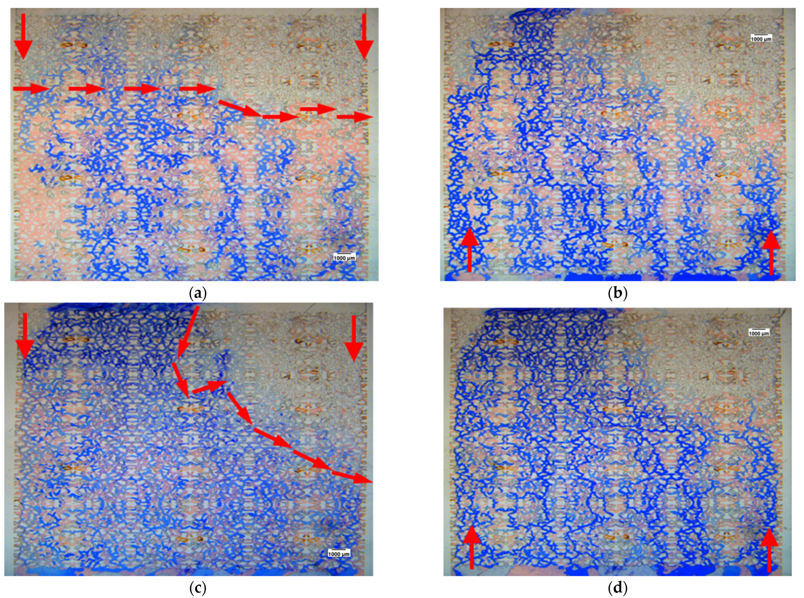
3.2.3. Water Shutoff of Gel

Figure 12 shows the experimental results of deep profile control using gel in a homogeneous model, and the recovery degree increased from 65.5% to 86.2%. In the homogeneous model, due to the high viscosity of the gel system, the effect of improving oil–water mobility was obvious during the injection process, and the gel advanced uniformly along the simulated “horizontal wellbore”. After 24 h of gelation, the gel system formed a thicker gel-blocking area near the wellbore. When the bottom water invaded again, the bottom water no longer advanced evenly along the bottom of the model, but made a breakthrough in certain areas that the gel blocked weakly. In this process, the remaining oil outside the gel-blocking area in the model was basically not used. In the homogeneous model, the gel system has a poor effect on locally concentrated residual oil and discontinuous residual oil in pore throats.
Figure 13 shows the results of a gel water shutoff experiment using the heterogeneous model; the recovery rose from 34.7% to 78.8%. In the heterogeneous model, mobility was greatly improved due to the high viscosity of the gel system. During the injection process, the depths of high- and low-permeability channels that the gel entered were similar, which seriously polluted the low-permeability layer. However, as the bottom water reinvaded, the gel system could effectively block both the high- and low-permeability layers. The injected water would break through in areas where the sealing strength was weak, and gel was very effective in exploiting the remaining oil in the low-permeability area.
Through the above experiments, the flow physics of gel as a horizontal well water shutoff in a bottom water reservoir is basically clear. (1) For a gel system with higher viscosity, it has a significant effect on improving mobility during the injection process; the wellbore of horizontal well advances evenly, which may pollute the low-permeability area; (2) a very strong plugging zone is formed after gelation, causing the subsequent bottom water to advance evenly along the bottom and break through at several points with weak plugging strength.

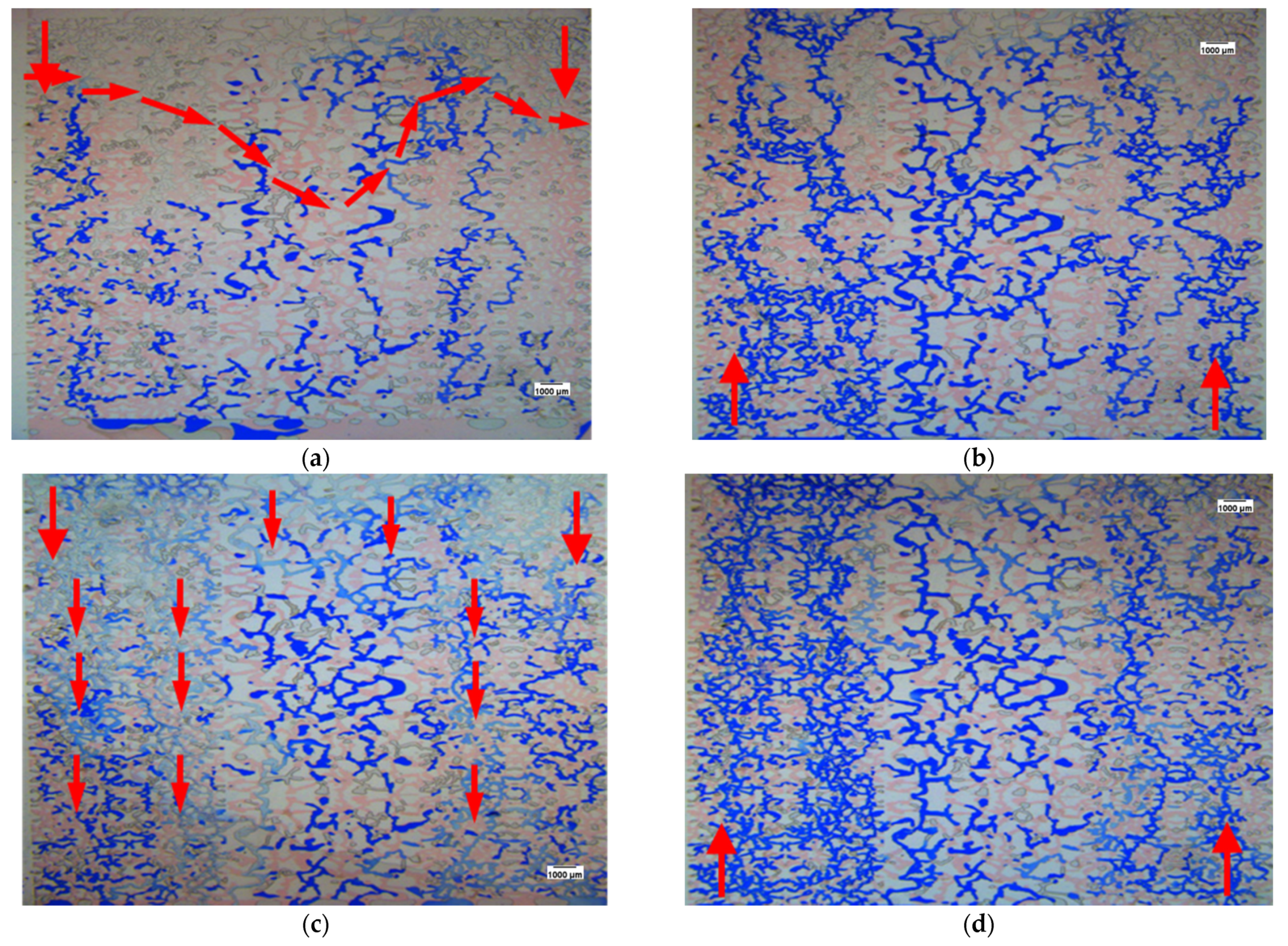
3.3. Flow Dynamics of Plugging Agents

The flow characteristics and action mechanism of three different types of plugging agents have been clarified in 3.2. A microsphere is an in-depth profile control agent with good selectivity to oil–water channels and is often used alone in oilfields to achieve enhanced oil recovery. The effect of the emulsifier on in-depth profile control is relatively weak, and it is basically ineffective for heterogeneous models; however, the emulsifier can effectively emulsify and mobilize residual oil through the process of the injection and re-invasion of bottom water. Although the gel system has strong plugging strength, its shortcomings include commingled water plugging, low-permeability layer pollution, and excessive plugging strength. In this context, multiple-cycle injection of the emulsifier and gel is often used in oilfields to achieve complementary advantages and avoid disadvantages, and combination plugging-control experiments were carried out to further study the synergistic effect.
After the first water invasion, 0.1 PV gel was injected to achieve high-strength plugging of the near-well channel flow channel. The results are shown in Figure 14a and Figure 15a. As described in 2.2, the gel system advanced uniformly in both homogeneous and heterogeneous models. In the process of second bottom water invasion, bottom water channeling occurred at one end of low gel-plugging strength in both models (Figure 14b and Figure 15b). Then 0.2 PV emulsifier was injected again along the horizontal wellbore. It can be seen from Figure 14c and Figure 15c that the emulsifier basically flowed along the second water invasion channel during the injection, realizing the mobilization of oil phase in the water invasion channel. As the third round of bottom water invaded, the bottom water also flowed along the emulsifier flow channel, as shown in Figure 14d and Figure 15d. We continued to inject 0.1 PV gel system along the wellbore area of the horizontal well. It can be seen from Figure 14e and Figure 15e that the gel system injected this time was no longer uniformly advanced, but mainly moved along the area where the gel accumulated in first injection. This indicates that a strong blocking area was formed in the area where the third bottom water invasion broke through, and the gel system cannot enter this area again, as shown in the marked areas in Figure 14e and Figure 15e. The fourth bottom water invasion was carried out after the gelation; the locally concentrated residual oil and discontinuous residual oil in pores were effectively produced in both homogeneous and heterogeneous models.
According to the definition of microscopic remaining oil swept area by Yu et al., the remaining oil occupying more than five pores is defined as continuous remaining oil, and the displacement occupied by continuous remaining oil is defined as the unswept area [17]. On this basis, the images in the above experiments can be determined by digital processing. In the homogeneous model, the first water invasion area is 77.2%, with a recovery degree of 62.1%; the second water invasion area after gel injection is 100%, with a recovery degree of 76.3%; the third water invasion area after emulsifier injection is 100%, with a recovery degree of 84.3%; the fourth water invasion area after the second gel injection is 100%, with a recovery degree of 93.2%. In the heterogeneous model, the first water invasion area is 40.3%, with a recovery degree of 36.2%; the second water invasion area after gel injection is 80.9%, with a recovery degree of 51.2%; the third water invasion area after emulsifier injection is 100%, with a recovery degree of 78.3%; the fourth water invasion area after the second gel injection is 100%, with a recovery degree of 86.2%. Compared with the results in 3.2, the combination of the gel system and emulsification exerts the synergistic effect of the two and realizes a greater effect of in-depth profile control.
Microscopic images were collected to reveal the synergistic effect of the emulsifier and gel system in experiments. Figure 16 shows the occurrence of the oil, water, and gel system after gelation. The gel was mainly distributed on the rock wall, leading to the narrowing and permeability loss of the channel. After the emulsifier was injected, the oil phase was emulsified into small oil droplets and flowed along the center of the channel. Figure 16c reveals the high-strength plugging area formed under the synergism of the gel and the emulsifier. The gel was present at the edge of the pores, and emulsified oil droplets occupied the pores. As a result, before the subsequent fluid could break through, it should not only break through the gel in the center of the pore body but also effectively mobilize dispersed oil droplets in the gel system. As shown in the figure, the plugging of the gel and the emulsion resulted in the emergence of a high-strength plugging area, realizing the synergism in in-depth profile control.
Through the above analysis, the synergistic mechanism of the gel and emulsifier system is clear: the gel is present at the edge of the pore body, while the emulsion is blocked in the center of the pore body. Hence, gel that enters the water channel (the main flow and accumulation area of the emulsion) can cooperate with the emulsion to achieve high-strength water shutoff, making the bottom water that re-invades mainly break through at oil-rich areas. Compared with water shutoff with gel alone (randomly distributed in the breakthrough area), the synergism improves the gel’s ability to select flow channels, inhibits emulsifier channeling, and achieves a remarkable EOR effect.

4. Conclusions

This paper simulates the experimental process of plugging agents for horizontal wells in bottom water reservoirs through a microfluidic model and studies the flow characteristics and mechanism of three types of plugging agents: a gel, microspheres, and emulsifiers. The main understandings are as follows:
(1) The emulsifier can mobilize and block part of the residual oil during the injection process. During the bottom water invasion, the residual oil will be driven again under the action of the emulsifier to form more emulsion. The main mechanisms of the emulsifier include the bypass effect of the emulsion blocking pore throats and the flow ability improvement of residual oil. The emulsifier performs better in homogeneous oil reservoirs because of less-serious channeling.
(2) The mobility of microsphere dispersion fluid is the same as that of the water phase. It flows along the channel of water phase and basically exerts no influence on the oil phase in other areas. Especially in heterogeneous reservoirs, the microspheres hardly enter and pollute the low-permeability area; however, the expanded microspheres can effectively block the channel, making the reinvading bottom water flow around and effectively extract the remaining oil out of the low-permeability area. The effect is very obvious in the heterogeneous reservoir.
(3) The combination of the emulsifier and the gel can reduce the amount of gel injected, and the emulsifier helps reduce the interfacial tension to employ residual oil. In addition, since the gel exists at the edge of the pore body and the emulsion is blocked in the center of the pore body, the gel entering the water channel (the main flow and storage area of the emulsion) can cooperate with the emulsion to achieve high-strength sealing, so that the bottom water invaded again mainly breaks through at the gel that enters the oil-rich region. Compared with pure gel water shutoff (the breakthrough area is randomly distributed), the synergy of the two can improve the flow channel selectivity of gel-plugging agents and inhibit the channeling of emulsifiers, and the recovery is the most considerable.

Author Contributions

Conceptualization was done by H.J. and Y.W.; the experimental design was done by J.L.; experiments were done by Y.W. and L.W.; writing the original draft preparation was done by Y.W.; writing the review and editing were done by L.L. All authors have read and agreed to the published version of the manuscript.

Funding

This research was funded by the National Science and Technology Major Project of China, grant number 2017ZX05009005-003 and Science Foundation of China University of Petroleum, Beijing, grant number No. 2462019QNXZ04.

Institutional Review Board Statement

Not applicable.

Informed Consent Statement

Not applicable.

Data Availability Statement

The data used to support the findings of this study are included within the article.

Acknowledgments

This research was supported by Major Program of National Natural Science Foundation of China (Grant ID: 2017ZX05009005-003) and Science Foundation of China University of Petroleum, Beijing (No. 2462019QNXZ04).

Conflicts of Interest

The authors declare that they have no conflict of interest.

References

  1. Luo, C.; Jia, A.; Guo, J.; He, D.; Wei, Y.; Luo, S. Analysis on effective reservoirs and length optimization of horizontal wells in the Sulige Gasfield. Nat. Gas Ind. B 2016, 3, 245–252. [Google Scholar] [CrossRef] [Green Version]
  2. Saikia, T.; Sultan, A.; Barri, A.A.; Khamidy, N.I.; Shamsan, A.A.; Almohsin, A.; Bataweel, M. Development of pickering emulsified polymeric gel system for conformance control in high temperature reservoirs. J. Pet. Sci. Eng. 2020, 184, 106596. [Google Scholar] [CrossRef]
  3. Chen, X.; Li, Y.; Liu, Z.; Zhang, J.; Chen, C.; Ma, M. Investigation on matching relationship and plugging mechanism of self-adaptive micro-gel (SMG) as a profile control and oil displacement agent. Powder Technol. 2020, 364, 774–784. [Google Scholar] [CrossRef]
  4. You, Q.; Wen, Q.; Fang, J.; Guo, M.; Zhang, Q.; Dai, C.L. Experimental study on lateral flooding for enhanced oil recovery in bottom-water reservoir with high water cut. J. Pet. Sci. Eng. 2019, 174, 747–756. [Google Scholar] [CrossRef]
  5. Zhou, D.; Jiang, T.; Feng, J.; Bian, W.; Liu, Y.; Zhao, J. Research of Water Flooded Performance and Pattern in Horizontal Well with Bottom-Water Drive Reservoir. In Proceedings of the Canadian International Petroleum Conference, Calgary, AB, Canada, 8–10 June 2004; Petroleum Society of Canada: Calgary, AB, Canada, 2004. [Google Scholar]
  6. Bai, Y.; He, S.; Lian, Y.; Dai, C.; Zhang, H. Giant surfactant-stabilized N2-foam for enhanced oil recovery after water flooding. RSC Adv. 2019, 9, 31551–31562. [Google Scholar] [CrossRef] [Green Version]
  7. Zhang, Y.; Gao, M.; You, Q.; Fan, H.; Li, W.; Liu, Y.; Fang, J.; Zhao, G.; Jin, Z.; Dai, C.L. Smart mobility control agent for enhanced oil recovery during CO2 flooding in ultra-low permeability reservoirs. Fuel 2019, 241, 442–450. [Google Scholar] [CrossRef]
  8. Hu, Z.; Yang, J.; Lu, B.; Hou, X.; Huang, X.; Gong, L.; Li, W.; Li, S. Hydrostatic pressure characteristics and pressure control mechanism of foam casing in deepwater wells. Acta Pet. Sin. 2019, 40, 726–733. [Google Scholar]
  9. Liang, B.; Jiang, H.; Li, J.; Chen, F.; Miao, W.; Yang, H.; Qiao, Y.; Chen, W. Mechanism study of disproportionate permeability reduction using nuclear magnetic reso-nance T2. Energy Fuels 2018, 32, 4959–4968. [Google Scholar] [CrossRef]
  10. Seright, R.S. Impact of dispersion on gel placement for profile control. SPE Reserv. Eng. 1991, 6, 343–352. [Google Scholar] [CrossRef]
  11. Seright, R.S. Polymer gel dehydration during extrusion through fractures. SPE Prod. Facil. 1999, 14, 110–116. [Google Scholar] [CrossRef] [Green Version]
  12. Lane, R.H.; Seright, R.S. Gel Water Shutoff in Fractured or Faulted Horizontal Wells. In Proceedings of the SPE/CIM International Conference on Horizontal Well Technology, Calgary, AB, Canada, 6–8 November 2000; Society of Petroleum Engineers: Calgary, AB, Canada, 2000. [Google Scholar]
  13. Liang, T.; Hou, J.; Qu, M.; Zhao, M.; Raj, I. High-viscosity α-starch nanogel particles to enhance oil recovery. RSC Adv. 2020, 10, 8275–8285. [Google Scholar] [CrossRef]
  14. Wang, Z.; Bai, B.; Long, Y.; Wang, L. An Investigation of CO2-Responsive Preformed Particle Gel for Conformance Control of CO2 Flooding in Reservoirs with Fractures or Fracture-Like Channels. SPE J. 2019, 24, 2398–2408. [Google Scholar] [CrossRef]
  15. Yang, J. Calculation method of surface conductor setting depth in deepwater oil and gas welss. Acta Pet. Sin. 2019, 40, 1396–1406. [Google Scholar]
  16. Khademolhosseini, R.; Jafari, A.; Mousavi, S.M.; Manteghian, M. Investigation of synergistic effects between silica nanoparticles, bio-surfactant and salinity in simultaneous flooding for enhanced oil recovery. RSC Adv. 2019, 9, 20281–20294. [Google Scholar] [CrossRef] [Green Version]
  17. Hu, Z.; Yang, J.; Li, W.; Li, S.; Feng, P.; Xin, Y. Research and development of compressible foam for pressure management in casing annulus of deepwater wells. J. Pet. Sci. Eng. 2018, 166, 546–560. [Google Scholar] [CrossRef]
  18. Yu, F.; Jiang, H.; Fan, Z.; Xu, F.; Su, H.; Li, J. Formation and Flow Behaviors of in Situ Emulsions in Heavy Oil Reservoirs. Energy Fuels 2019, 33, 5961–5970. [Google Scholar] [CrossRef]
  19. Hu, Z.; Yang, J.; Liu, S.; Li, W.; Li, S.; Tong, G. Prediction of sealed annular pressure between dual packers in HPHT deepwater wells. Arab. J. Geosci. 2018, 11, 489. [Google Scholar] [CrossRef]
  20. Yu, F.; Jiang, H.; Xu, F.; Fan, Z.; Su, H.; Li, J. New insights into flow physics in the EOR process based on 2.5D reservoir micromodels. J. Pet. Sci. Eng. 2019, 181, 106214. [Google Scholar] [CrossRef]
  21. Xu, K.; Liang, T.; Zhu, P.; Qi, P.; Lu, J.; Huh, C.; Balhoff, M. A 2.5-D glass micromodel for investigation of multi-phase flow in porous media. Lab Chip 2017, 17, 640–646. [Google Scholar] [CrossRef]
  22. Xu, K.; Zhu, P.; Colon, T.; Huh, C.; Balhoff, M. A Microfluidic Investigation of the Synergistic Effect of Nanoparticles and Surfactants in Macro-Emulsion-Based Enhanced Oil Recovery. SPE J. 2017, 22, 459–469. [Google Scholar] [CrossRef]
  23. Xu, K.; Agrawal, D.K.; Darugar, Q. Hydrophilic Nanoparticle-Based Enhanced Oil Recovery: Microfluidic Investigations on Mechanisms. Energy Fuels 2018, 32, 11243–11252. [Google Scholar] [CrossRef]
  24. Yu, F.; Jiang, H.; Fan, Z.; Xu, F.; Su, H.; Cheng, B.; Liu, R.; Li, J. Features and imbibition mechanisms of Winsor I type surfactant solution in oil-wet porous media. Pet. Explor. Dev. 2019, 46, 1006–1013. [Google Scholar] [CrossRef]
  25. Sendekie, Z.B.; Bacchin, P. Colloidal jamming dynamics in microchannel bottlenecks. Langmuir 2016, 32, 1478–1488. [Google Scholar] [CrossRef] [Green Version]
  26. Liang, B.; Jiang, H.; Li, J.; Seright, R.S.; Lake, L.W. Further insights into the mechanism of disproportionate permeability reduction. In Proceedings of the SPE Annual Technical Conference and Exhibition, San Antonio, TX, USA, 9–11 October 2017; Society of Petroleum Engineers: Calgary, AB, Canada, 2017. [Google Scholar]
  27. Su, H.; Zhou, F.; Wang, Q.; Yu, F.; Dong, R.; Xiong, C.; Li, J.; Liang, T. Flow Physics of Polymer Nanospheres and Diluted Microemulsion in Fractured Carbonate Reservoirs: An Investigation into Enhanced Oil Recovery Mechanisms. SPE J. 2021, 26, 2231–2244. [Google Scholar] [CrossRef]
Figure 1. Two types of microfluidic models. (a) The schematic diagram of the homogeneous model; (b) the homogeneous model; (c) the schematic diagram of a heterogeneous model; (d) the heterogeneous model.
Processes 10 00112 g001
Figure 2. Emulsion phase behavior as a function of time at reservoir temperature. (a) Emulsion phase behavior as a function of time at reservoir temperature; (b) the microscopic images of the emulsion at 1 h; (c) the microscopic images of the emulsion at 10 h; (d) the microscopic images of the emulsion at 24 h.
Processes 10 00112 g002
Figure 3. The particle size test results of nano-microspheres under different standing times. (a) The newly prepared dispersion on (b) day 1, (c) day 2, and (d) day 3.
Processes 10 00112 g003aProcesses 10 00112 g003b
Figure 4. The newly configured gel system (a) and the gel system after gelation (b).
Processes 10 00112 g004
Figure 5. The microscopic image of the homogeneous model water flooding process. (a) Saturated oil and (b) end of water flooding.
Processes 10 00112 g005
Figure 6. Emulsifier injection and subsequent water-invasion images of the homogeneous model: (a) the emulsifier is injected along the simulated “horizontal wellbore” and (b) the end of the second water flooding.
Processes 10 00112 g006
Figure 7. Heterogeneous model emulsifier injection and subsequent water invasion images: (a) saturated oil; (b) end of the first water flooding; (c) the emulsifier injected along the simulated “horizontal wellbore”; (d) end of the second water flooding.
Processes 10 00112 g007
Figure 8. Emulsion water plugging mechanism diagram under the action of the emulsifier: (a) the schematic diagram of the emulsion water-plugging mechanism; (b) 0 s; (c) 100 s; (d) 200 s.
Processes 10 00112 g008
Figure 9. The subsequent water invasion process diagram after polymer microsphere injection and microsphere expansion in the homogeneous model. (a) The microsphere is injected along the simulated “horizontal wellbore”; (b) end of the second water flooding.
Processes 10 00112 g009
Figure 10. The subsequent water invasion process diagram after polymer microsphere injection and microsphere expansion in the heterogeneous model. (a) The emulsifier is injected along the simulated “horizontal wellbore”; (b) end of the second water flooding.
Processes 10 00112 g010
Figure 11. Water shutoff mechanism of polymer microspheres. (a) The distribution of polymer microspheres in the channel before expansion; (b) no permeability loss before expansion; (c) the distribution of polymer microspheres in the channel after expansion; (d) permeability loss caused by blocked pores after the expansion of polymer microspheres.
Processes 10 00112 g011
Figure 12. Injection of homogeneous model gel system and subsequent water invasion images. (a) The gel is injected along the simulated “horizontal wellbore”; (b) end of the second water flooding.
Processes 10 00112 g012
Figure 13. Process diagram of heterogeneous model gel injection and subsequent water flooding. (a) gel injection, (b) subsequent water flooding.
Processes 10 00112 g013
Figure 14. The process diagram of the homogeneous model gel-emulsifier compound water shutoff process. (a) The first gel injection, (b) the second water invasion, (c) the first emulsifier injection, (d) the third water invasion, (e) the second gel injection, (f) the fourth water invasion.
Processes 10 00112 g014aProcesses 10 00112 g014b
Figure 15. The process diagram of the heterogeneous model gel-emulsifier compound water shutoff process. (a) The first gel injection, (b) the second water invasion, (c) the first emulsifier injection, (d) the third water invasion, (e) the second gel injection, (f) the fourth water invasion.
Processes 10 00112 g015aProcesses 10 00112 g015b
Figure 16. Microscopic image of gel-emulsifier composite water shutoff and analysis of water shutoff mechanism. (a) After the gel is injected, the main channel of the gel system stays on the rock wall, causing the oil–water circulation channel to narrow to block the water channel. (b) After the emulsifier is injected, the formed emulsion mainly stays in the center of the pore to realize the blocking of the water channel. (c) Under the synergistic effect of the gel and the emulsifier, the gel system stays at the edge of the pore body, and the emulsion stays in the center of the pore body.
Processes 10 00112 g016
Publisher’s Note: MDPI stays neutral with regard to jurisdictional claims in published maps and institutional affiliations.

