
Solar Desalination Driven by Organic Rankine Cycles (Orc) and Supercritical CO2 Power Cycles: An Update


Abstract
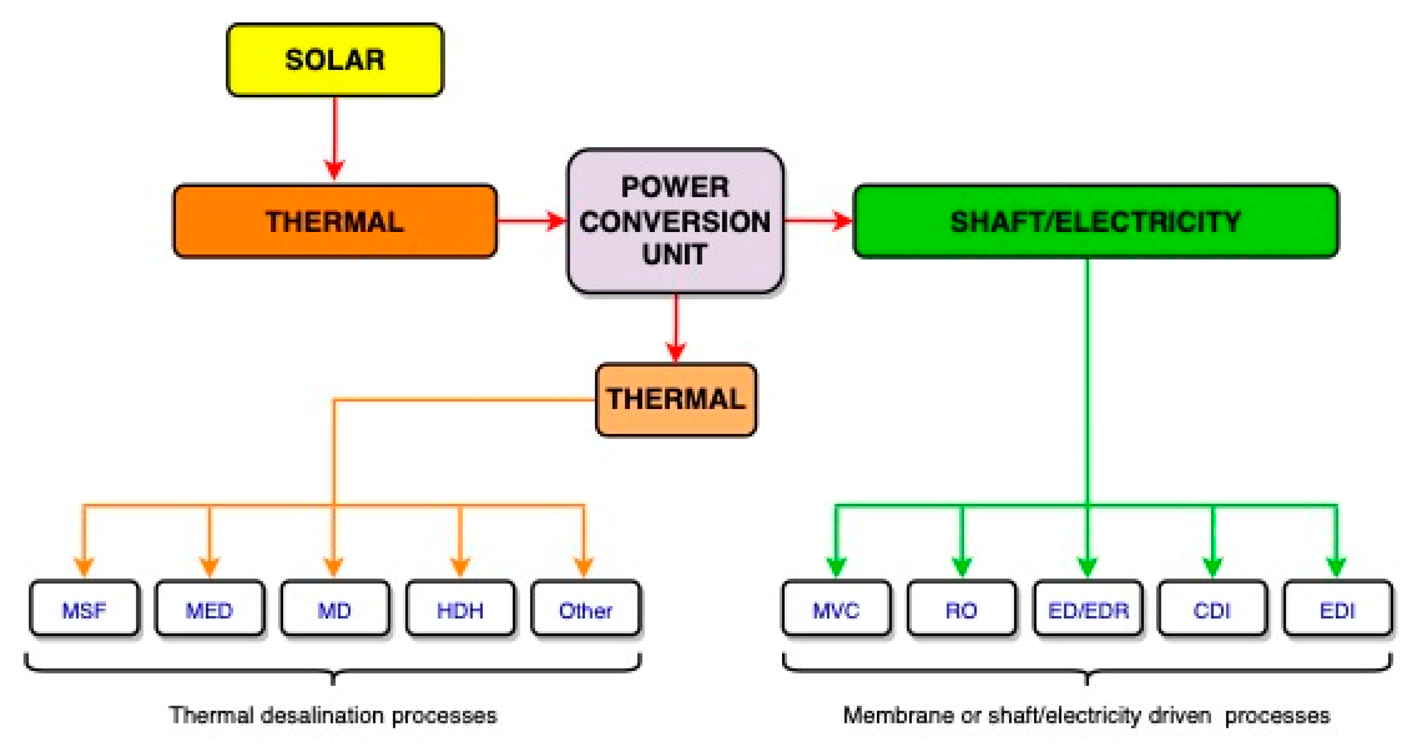
:1. Introduction
2. Solar ORC (Organic Rankine Cycle)-Driven Desalination Systems: An Update
2.1. Integration of Reverse Osmosis (RO) as Desalination Technology
2.1.1. Medium-Temperature Solar Systems
2.1.2. Low-Temperature Solar Systems
2.2. Integration of Thermal Processes as Desalination Technology
- MED unit. A set of several chambers (so-called effects) are kept under vacuum conditions with decreasing pressures, corresponding to the saturation pressure at decreasing temperatures from 50 to 67 °C, up to 45–35 °C. Normally there is a single heat exchanger consisting of a horizontal tube bundle and the evaporator. An external flow, providing the external heat source of the MED process, circulates within the evaporator tubes of the first effect. Seawater feed with slight preheating is sprayed on the surface of the tube bundle, thus resulting in a thin film that is partially evaporated. The remaining brine is discharged by the bottom of the effect, whereas the steam generated is sent to circulate inside the tubes of the evaporator of the next effect. The steam generated in the last effect is condensed in the end condenser. A seawater flow circulates through the end condenser; part of this flow (seawater cooling) is discharged back to the sea and the rest of the flow is the preheated seawater that enters all effects in parallel. Industrial plants normally have 8–12 effects in MED units and 4–8 effects in MED-TVC, although designs with 14 effects are feasible, with an average of around 2.5 °C of temperature gradient between adjacent effects. With 14 effects, the thermal energy consumption would be about 230 kJ/kg in a MED unit and 166 kJ/kg in MED-TVC.
- Termocompressor. A high-pressure steam flow (motive steam) is mixed with a low-pressure steam flow, thus resulting in a steam flow with intermediate pressure and temperature. This outlet steam flow drives the MED process: the low-pressure flow is the steam generated at the last effect or one of the last effects, whereas the motive steam is generated by the available heat source. In conventional MED-TVC plants, the motive steam is a turbine extraction. Steam at about 140–225 °C is required in MED-TVC plants. Coupling the thermocompressor to the MED plant at the last effect makes the end condenser unneccesary. This results in avoiding the seawater cooling flow that requires significant electricity consumption, along with increased capital cost attributable to seawater intake infrastructure and pumps.
2.3. Proposals with Integration of Hybrid RO/Thermal Desalination
3. Solar sCO2 Power Cycle and Desalination
4. Assessment of Innovative Configuration of CSP + D Plants
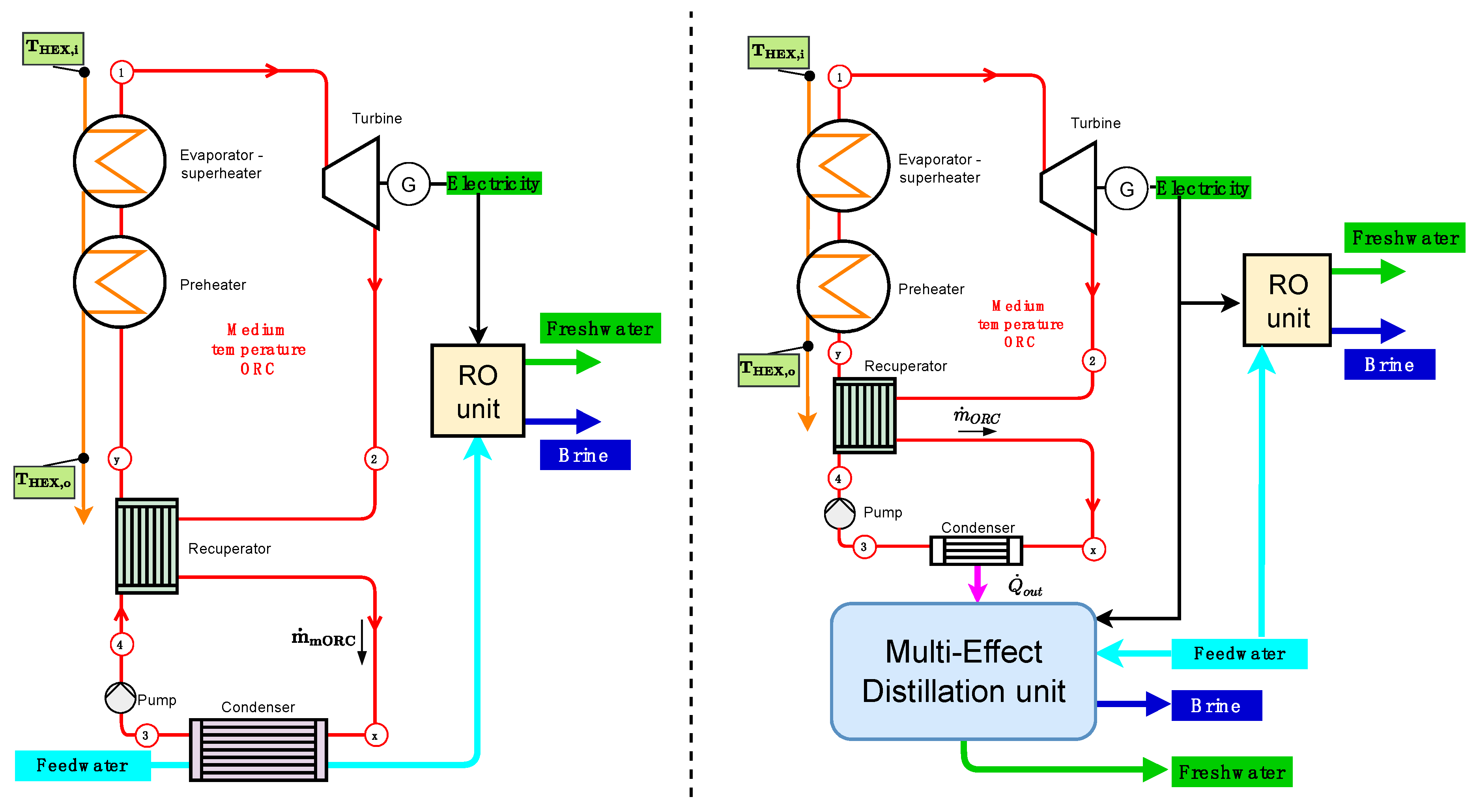
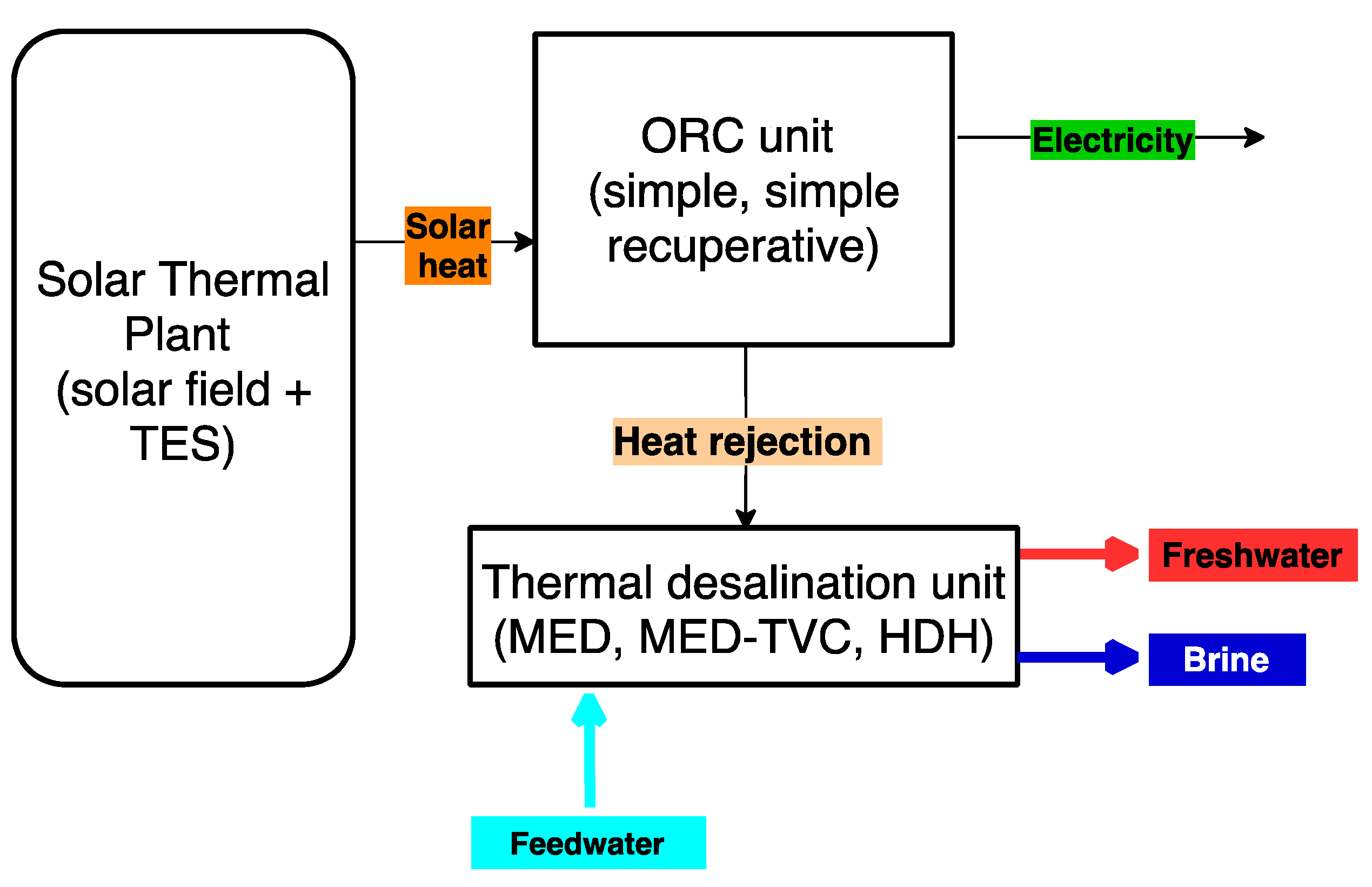
- There is an important number of proposals of solar ORC systems in which desalinated water is produced by means of a thermal process that receives the heat discharged by the cycle. The most common technology is MED, although it is also possible to find some designs with HDH. First, auxiliary consumption of thermal desalination processes should be taken into account in comparison to that of RO desalination, as Section 4.1 describes. Second, the coupling of thermal desalination to an ORC requires an increase in condensing temperature. This results in the lower energy efficiency of the ORC in thermal desalination applications, which should be compared to ORC/RO desalination (see Section 4.2).
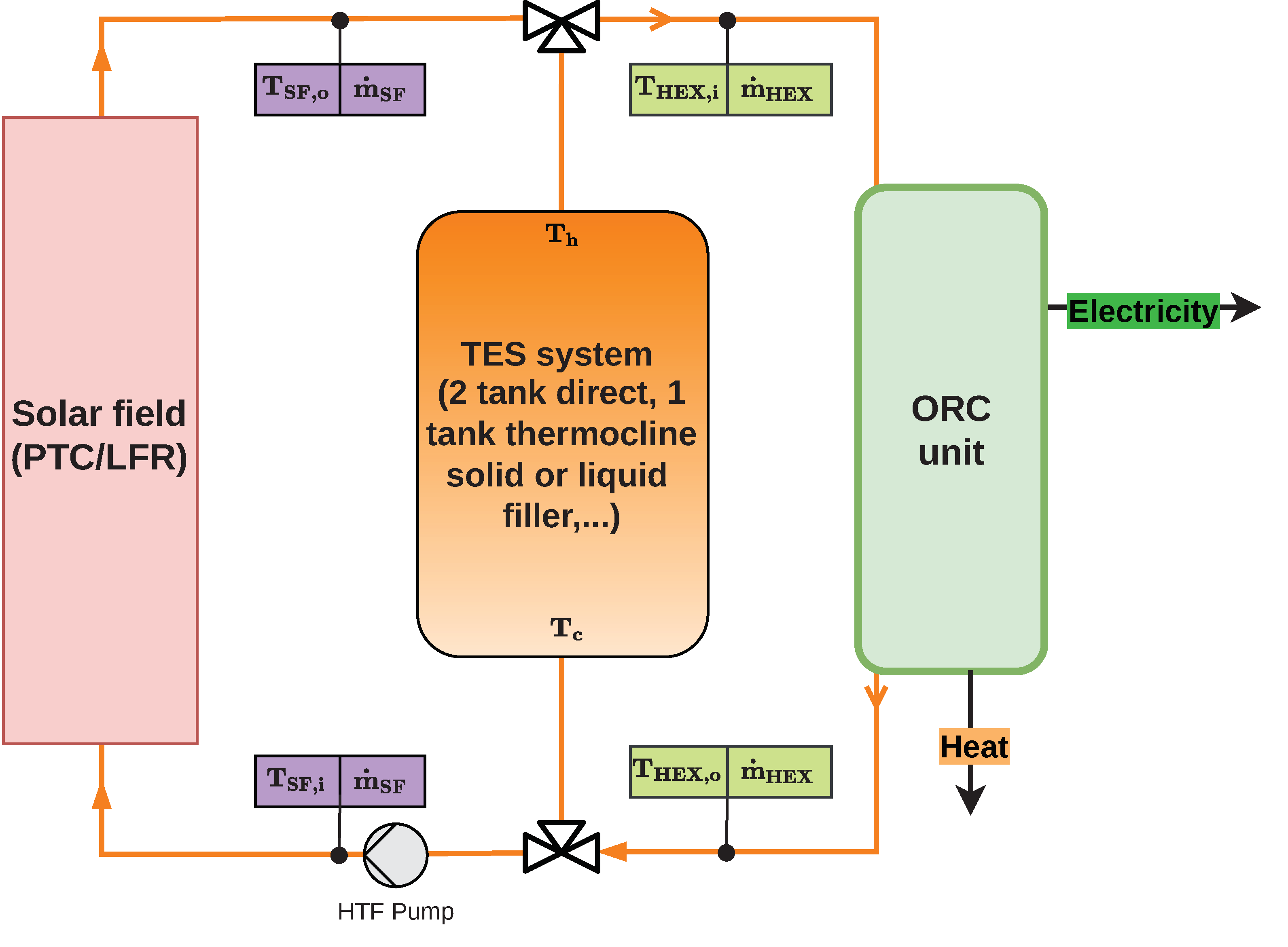
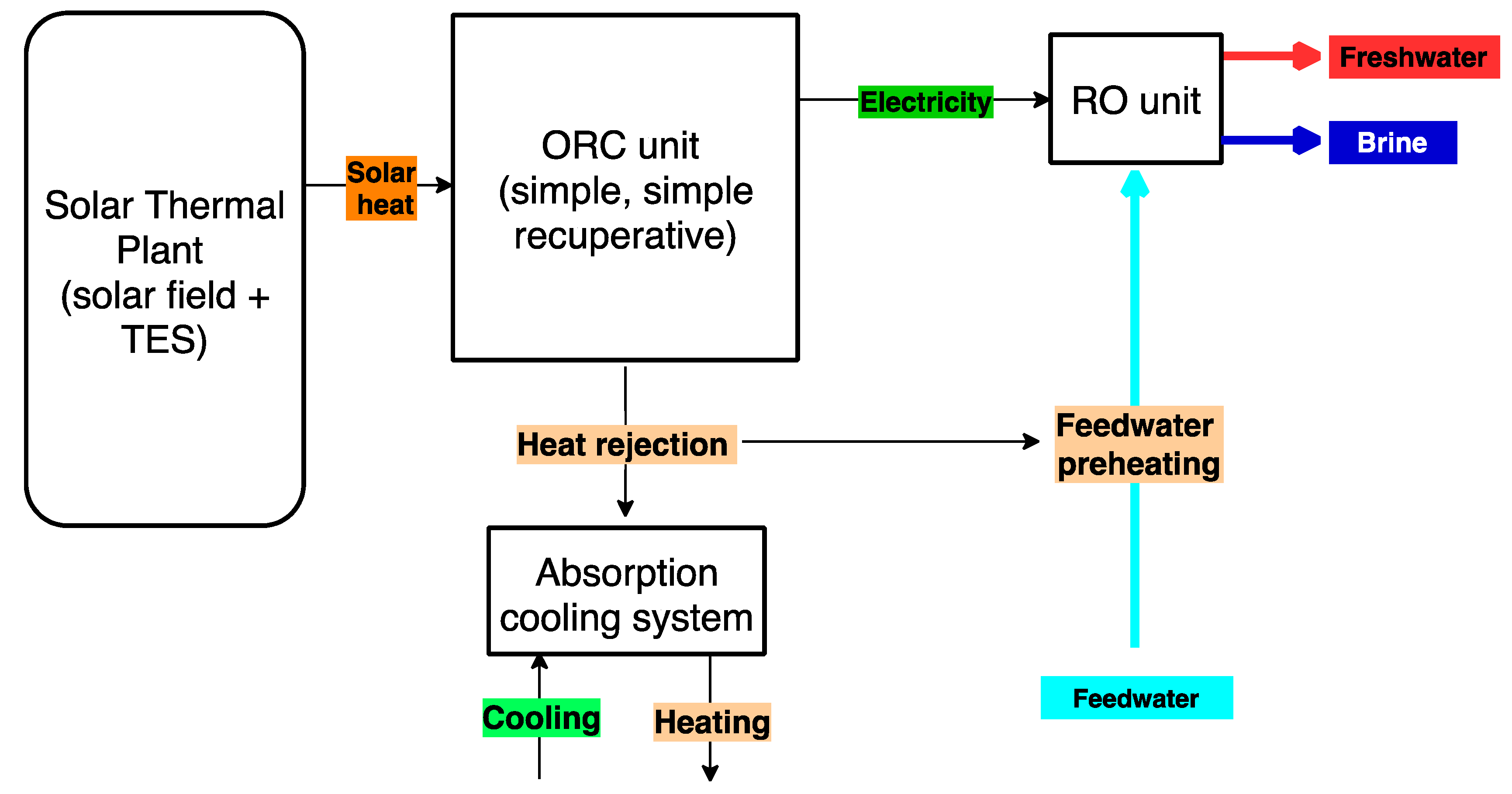
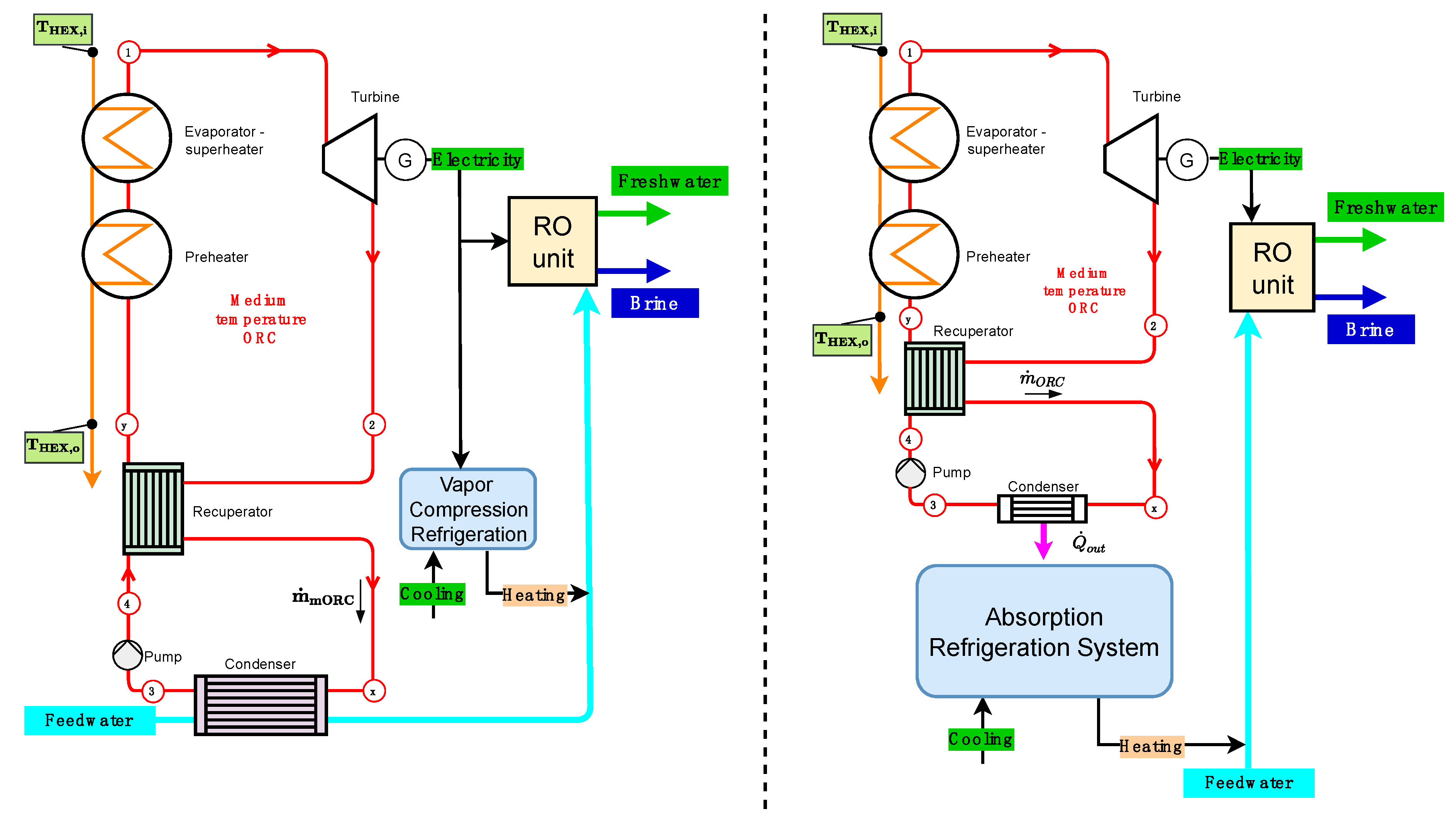
- Concerning solar ORC-RO technology with a solar thermal system in the medium-temperature range, most designs focus on PTCs and thermal storage in addition to the use of the heat rejected by the cycle for other processes, mainly cooling by single-effect absorption. The use of this heat for the preheating of the RO feed water is also considered. The assessment of poly- or multi-generation schemes in solar ORC, including cooling applications, requires further analysis focused on the effect of condensing temperature of the power cycle, presented in Section 4.2. Moreover, the proposed seawater preheating should be assessed case by case, having regard to regulations of product quality since a temperature increase makes the compliance of boron content difficult. Further treatment of product water could be required, thus increasing capital and operation expenses. Therefore, no general conclusion can be pointed out in this regard.
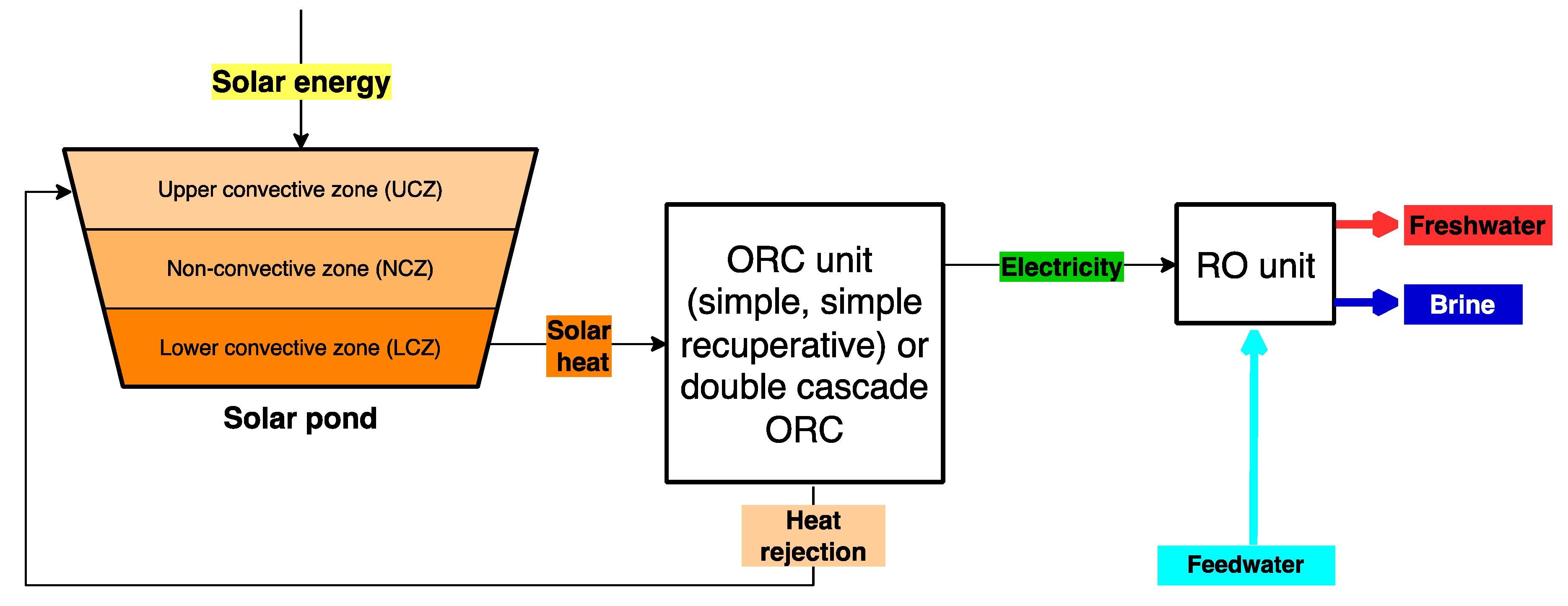
- When low-temperature ORC is considered to drive the RO, the most common option is a solar pond being used as a solar thermal collector and storage system. In this case, heat is supplied to the ORC from the lower convective zone of the SP and the upper convective zone is the cold sink. The combined system SP/ORC/RO exhibits the highest solar energy consumption in comparison to any other solar desalination technology [7]. However, this option is inexpensive due to three main reasons: the RO desalination system can operate 24 h/day most of the year, no additional energy storage is required, and the low cost of the SP technology.
- In relation to the coupling of desalination processes with solar sCO2 cycles, it has been noted that there are few design proposals to date. Most of them correspond to the use of the heat rejected by the cycle to drive MED plants. As a common feature in all of them, not all the waste heat of the cycle contributes to the desalination process. The coupling of thermal desalination and solar power cycles based on sCO2 has a lower effect on the cycle efficiency than that of solar ORCs. Innovative configurations of MED plants, such as those proposed by Omar et al. [54] and Sharan et al. [56], have significant market prospects as cost-effective solutions. However, Sharan et al. [56] reported on maximum freshwater production of about 2500 m3/d in a solar sCO2 plant of 115 MW of net power output. This means a ratio of desalination production to power output of 21.7 m3/d/MW, so higher water demands should be provided by RO desalination.
4.1. Auxiliary Energy Consumption in Thermal Desalination
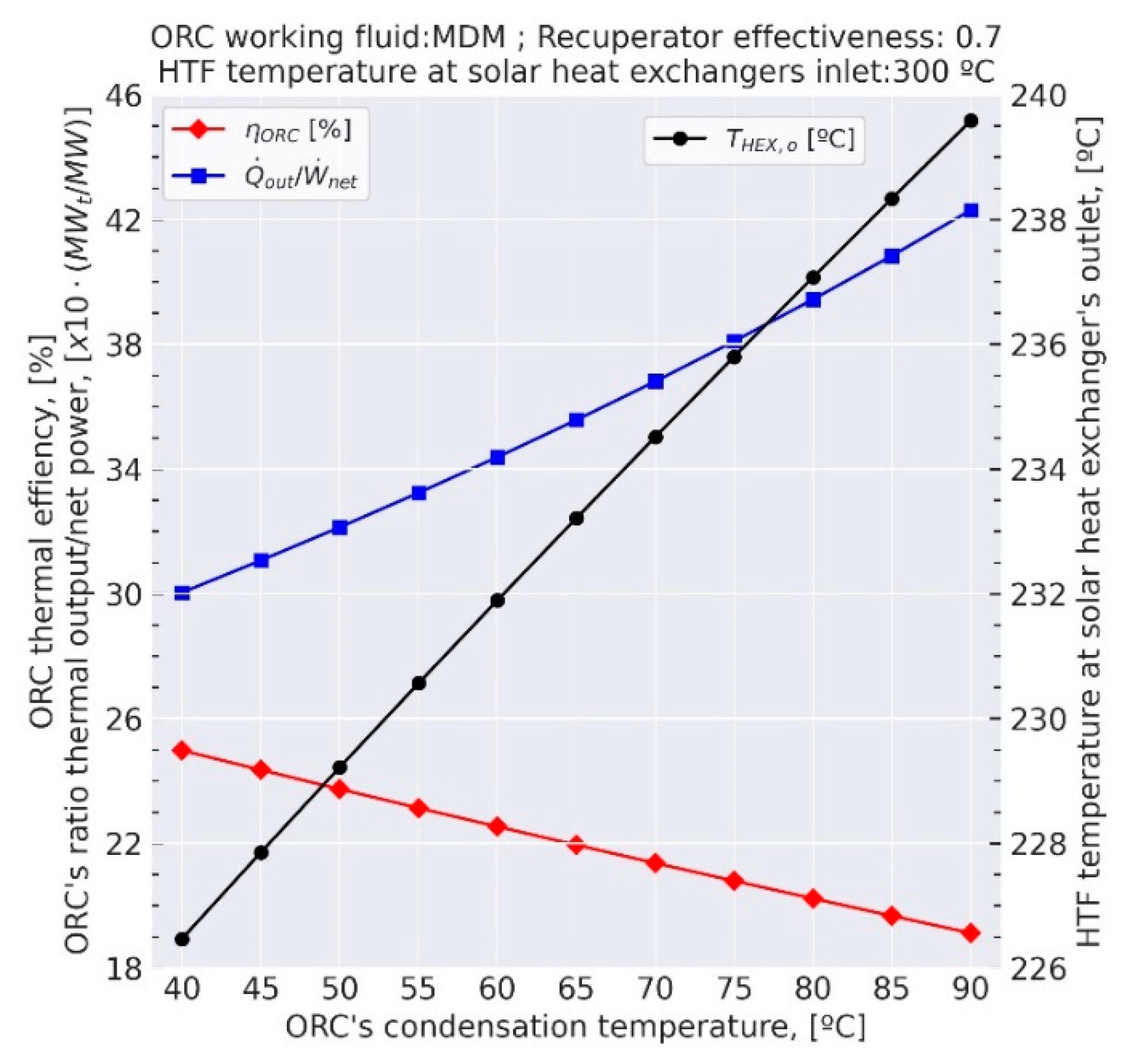
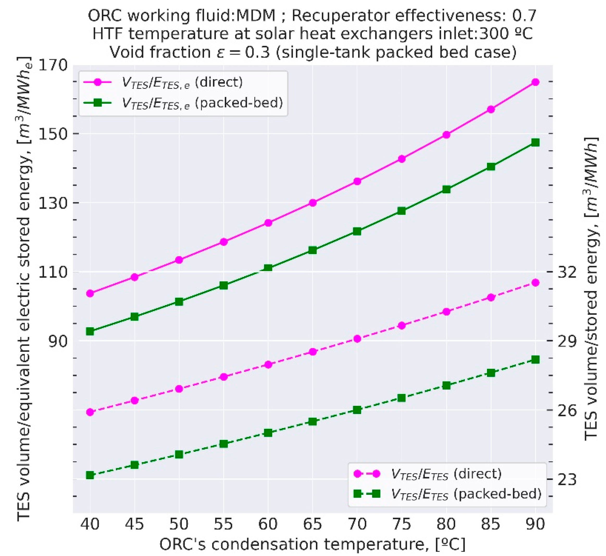
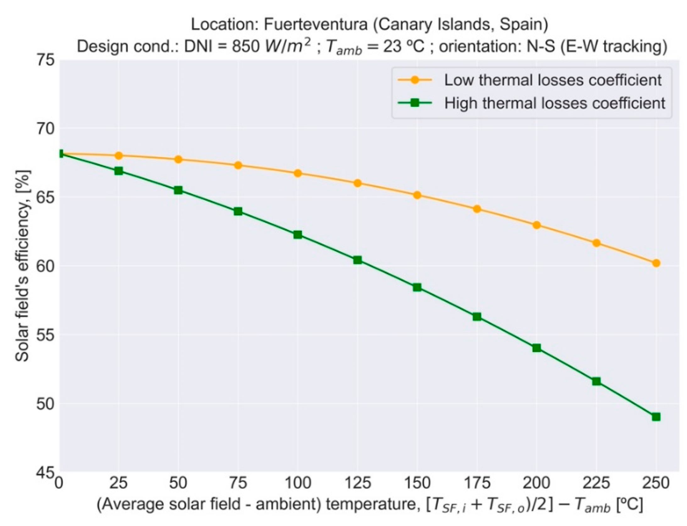
4.2. Effect of Condensing Temperature in Medium-Temperature ORCs
5. Conclusions and Recommendations
- In remote locations, solar desalination systems based on solar-pond-driven ORC/RO should be studied in comparison to solar PV/RO plants to supply only the freshwater demand.
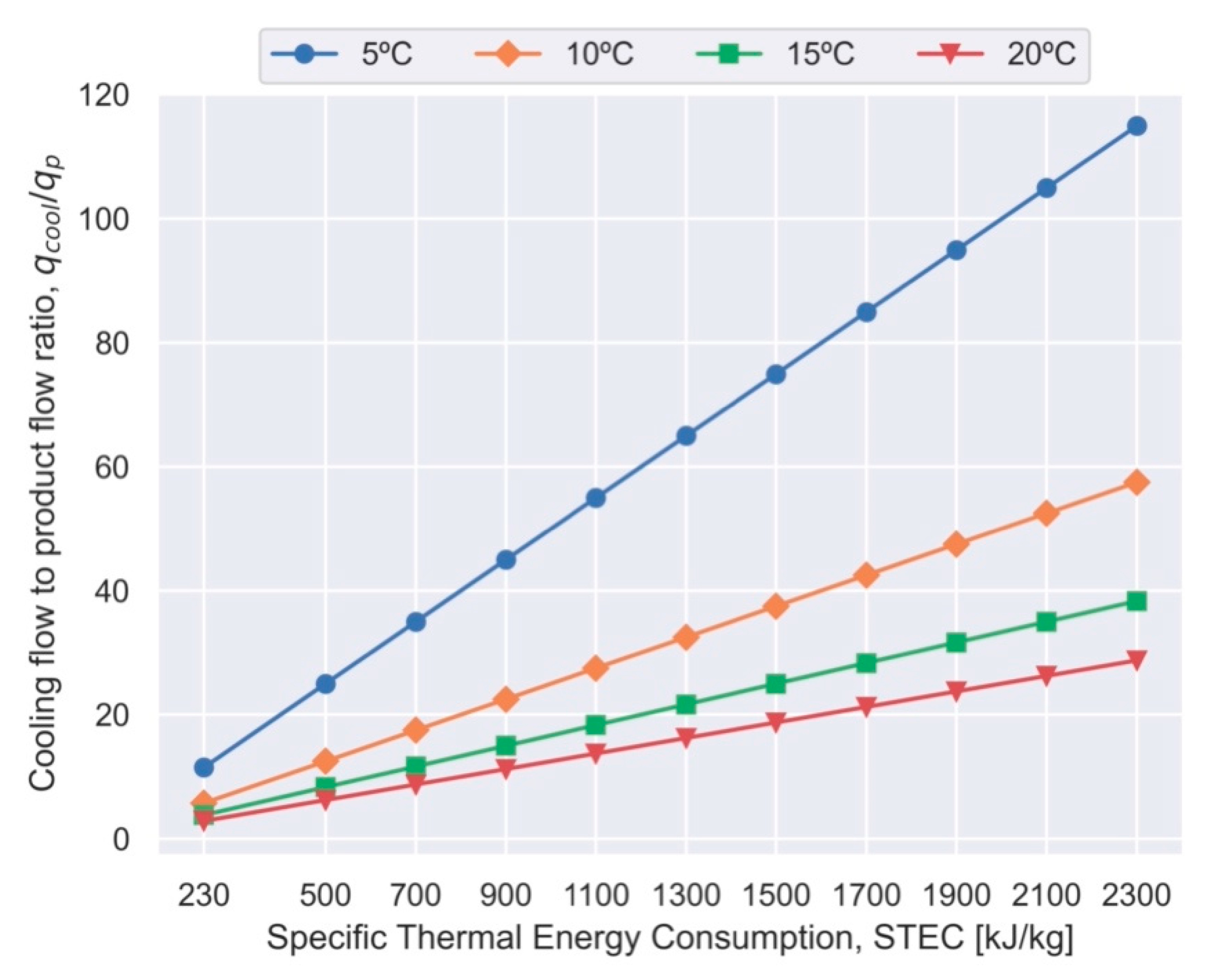
- Concerning the selection of thermal desalination versus reverse osmosis, design proposals should consider the extra costs attributable to cooling flow, namely, capital expenses of seawater intake and pumping systems, along with pumping electricity consumption (see Figure 5).
- A comparative analysis of solar ORC/RO combined with cooling technologies has been performed. The use of the heat rejected by the cycle to drive an absorption refrigeration system is superior since results show that a bigger solar field and storage system would be needed to supply the same cooling capacity with a mechanical vapor compression refrigeration system (see Table 5).
- A comparative analysis has also been carried out to compare solar ORC/MED and solar ORC/RO desalination. Auxiliary electricity consumption of 0.75 kWh/m3 is assumed in seawater RO desalination, attributable to the control system and feed pumping, whereas 2 kWh/m3 has been considered in MED plants due to the additional requirements of a vacuum system and cooling flow pumping (see Figure 5). Results (see Table 4) show that thermal desalination is not recommended to exploit the heat rejection of the power cycle since the condensing temperature must be increased to couple the MED unit.
- On the contrary, heat rejection of sCO2 cycles in CSP plants may be economically exploited by innovative MED desalination plants with the so-called cascade design depending on both local regulations of discharge temperature and the corresponding auxiliary pumping of cooling flow. Water production is limited to the waste heat available, so in the case of higher water demands, RO desalination is the only option recommended. Either seawater feed or concentrate flows of the RO plant can be used as the cooling flow of the power cycle, up to the maximum limit of temperature discharge.
Author Contributions
Funding
Institutional Review Board Statement
Informed Consent Statement
Acknowledgments
Conflicts of Interest
References
- International Energy Agency, IEA. Data and Statistics Page. Available online: https://www.iea.org/data-and-statistics/data-browser?country=WORLD&fuel=Energysupply&indicator=TESbySource (accessed on 31 October 2021).
- The World Bank. DataBank. World Development Indicators. Available online: https://databank.worldbank.org/source/world-development-indicators (accessed on 31 October 2021).
- Ihsanullah, I.; Atieh, M.A.; Sajid, M.; Nazal, M.K. Desalination and Environment: A Critical Analysis of Impacts, Mitigation Strategies, and Greener Desalination Technologies. Sci. Total Environ. 2021, 780, 146585. [Google Scholar] [CrossRef] [PubMed]
- Lee, K.; Jepson, W. Environmental Impact of Desalination: A Systematic Review of Life Cycle Assessment. Desalination 2021, 509, 115066. [Google Scholar] [CrossRef]
- Zapata-Sierra, A.; Cascajares, M.; Alcayde, A.; Manzano-Agugliaro, F. Worldwide Research Trends on Desalination. Desalination 2021, 519, 115305. [Google Scholar] [CrossRef]
- Ghaffour, N.; Bundschuh, J.; Mahmoudi, H.; Goosen, M.F.A. Renewable Energy-Driven Desalination Technologies: A Comprehensive Review on Challenges and Potential Applications of Integrated Systems. Desalination 2015, 356, 94–114. [Google Scholar] [CrossRef] [Green Version]
- Pouyfaucon, A.B.; García-Rodríguez, L. Solar Thermal-Powered Desalination: A Viable Solution for a Potential Market. Desalination 2018, 435, 60–69. [Google Scholar] [CrossRef]
- Alnaimat, F.; Ziauddin, M.; Mathew, B. A review of recent advances in humidification and dehumidification desalination technologies using solar energy. Desalination 2021, 499, 114860. [Google Scholar] [CrossRef]
- Alarcón-Padilla, D.C.; García-Rodríguez, L.; Blanco-Gálvez, J. Design recomendations for a multi-effect distillation plant connected to a double-effect absortion heat pump: A solar desalination case-study. Desalination 2010, 262, 11–14. [Google Scholar] [CrossRef]
- Alarcón-Padilla, D.C.; García-Rodríguezz, L.; Blanco-Gálvez, J. Experimental assessment of connection of an absorption heat pump to a multi-effect distillation unit. Desalination 2010, 250, 500–505. [Google Scholar] [CrossRef]
- Alarcón-Padilla, D.C.; Blanco-Gálvez, J.; García-Rodríguezz, L.; Gernjak, W.; Malato-Rodríguez, S. First experimental results of a new hybrid solar/gas multi-effect distillation system: The AQUASOL Project. Desalination 2008, 220, 619–625. [Google Scholar] [CrossRef]
- Hassan, A.M. Fully Integrated NF-Thermal Seawater Desalination Process and Equipment Therefor. European Patent Application EP 1 614 660 A1, 9 July 2004. [Google Scholar]
- Hassan, A.M. Fully Integrated NF-Thermal Seawater Desalination Process and Equipment. U.S. Patent US 20060157410, 20 July 2006. [Google Scholar]
- Hassan, A.M. Process for Desalination of Saline Water, Especially Water, Having Increased Product Yield and Quality. U.S. Patent US 6508903, 21 January 2003. [Google Scholar]
- Hassan, A.M.; Al-Sofi, M.A.K.; Al-Amoudi, A.S.; Jamaluddin, A.T.M.; Farooque, A.M.; Rowaili, A.; Dalvi, A.G.I.; Kither, N.M.; Mustafa, G.M.; Al-Tisan, I.A.R. A new approach to membrane and thermal seawater desalination processes using nanofiltration membranes (part 1). Desalination 1998, 118, 35–51. [Google Scholar] [CrossRef]
- Wilf, M.; Awerbuch, L. The Guidebook to Membrane Desalination Technology; Balaban Desalination Publications: L’Aquila, Italy, 2007; ISBN 0-86689-065-3. [Google Scholar]
- Palenzuela, P.; Zaragoza, G.; Alarcón-Padilla, D.C.; Guillén, E.; Ibarra, M.; Blanco, J. Assessment of different configurations for combined parabolic-trough (PT) solar power and desalination plants in arid regions. Energy 2011, 36, 4950–4958. [Google Scholar] [CrossRef]
- Ortega-Delgado, B.; Palenzuela, P.; Alarcón-Padilla, D.C.; García-Rodríguez, L. Quasi-steady state simulations of thermal vapor compression multi-effect distillation plants coupled to parabolic trough solar thermal power plants. Desalin. Water Treat. 2016, 57, 23085–23096. [Google Scholar] [CrossRef]
- Ortega-Delgado, B.; Palenzuela, P.; Alarcón-Padilla, D.-C. Parametric study of a multi-effect distillation plant with thermal vapor compression for its integration into a Rankine cycle power block. Desalination 2016, 394, 18–29. [Google Scholar] [CrossRef]
- Hanafi, A.S.; Mostafa, G.M.; Waheed, A.W.; Fathy, A. I-D mathematical modeling and CFD investigation on supersonic steam ejector in MED-TVC. Energy Procedia 2015, 75, 3239–3252. [Google Scholar] [CrossRef] [Green Version]
- Ameri, M.; Mohammadi, S.S.; Hosseini, M.; Seifi, M. Effect of design parameters on multi-effect desalinationsystem specifications. Desalination 2009, 245, 266–283. [Google Scholar] [CrossRef]
- Mazini, M.T.; Yazdizadeh, A.; Ramezani, M.H. Dynamic modelling of multi-effect desalination with thermal vapour compressor plant. Desalination 2014, 353, 98–108. [Google Scholar] [CrossRef]
- Kouhikamali, R.; Sanaei, M.; Mehdizadeh, M. Process investigation of different locations of thermo-compressor suction in MED–TVC plants. Desalination 2011, 280, 134–138. [Google Scholar] [CrossRef]
- Esfahani, I.J.; Ataei, A.; Shetty, K.V.; Oh, T.; Park, J.H.; Yoo, C. Modeling and genetic algorithm-based multi-objective optimization of the MED-TVC desalination system. Desalination 2012, 292, 87–104. [Google Scholar] [CrossRef]
- Temstet, C.; Canto, G.; Laborie, J.; Durante, A. A large high-performance MED plant in Sicily. Desalination 1996, 105, 109–114. [Google Scholar] [CrossRef]
- Al-Mutaz, I.S.; Wazeer, I. Development of a steady-state mathematical model for MEE-TVC desalination plants. Desalination 2014, 351, 9–18. [Google Scholar] [CrossRef]
- Fernández-Izquierdo, P.; García-Rodríguez, L.; Alarcón-Padilla, D.C.; Palenzuela, P.; Martín-Mateos, I. Experimental analysis of multi-effect distillation unit operated out of nominal conditions. Desalination 2012, 284, 233–237. [Google Scholar] [CrossRef]
- Maurel, A. Dessalement et Energies Nouvelles. Desalination 1979, 31, 489–499. [Google Scholar] [CrossRef]
- Libert, J.J.; Maurel, A. Desalination and Renewable Energies-a Few Recent Developments. Desalination 1981, 39, 363–372. [Google Scholar] [CrossRef]
- Delgado-Torres, A.M.; García-Rodríguez, L.; Peñate, B.; de la Fuente, J.A.; Melián, G. Water Desalination by Solar-Powered RO Systems. In Current Trends and Future Developments on (Bio-) Membranes: Renewable Energy Integrated with Membrane Operations; Cassana, A., Figoli, A., Basile, A., Eds.; Elsevier: Amsterdam, The Netherlands, 2018; ISBN 978-0-12-813545-7. [Google Scholar] [CrossRef]
- Ghermandi, A.; Messalem, R. Solar-Driven Desalination with Reverse Osmosis: The State of the Art. Desalin. Water Treat. 2009, 7, 285–296. [Google Scholar] [CrossRef] [Green Version]
- Delgado-Torres, A.M.; García-Rodríguez, L. Design Recommendations for Solar Organic Rankine Cycle (ORC)-Powered Reverse Osmosis (RO) Desalination. Renew. Sustain. Energy Rev. 2012, 16, 44–53. [Google Scholar] [CrossRef]
- Shalaby, S.M. Reverse Osmosis Desalination Powered by Photovoltaic and Solar Rankine Cycle Power Systems: A Review. Renew. Sustain. Energy Rev. 2017, 73, 789–797. [Google Scholar] [CrossRef]
- Yuan, L.; Zhu, Q.; Zhang, T.; Duan, R.; Zhu, H. Performance evaluation of a co-production system of solar thermal power generation and seawater desalination. Renew. Energy 2021, 169, 1121–1133, Corrigendum in Renew. Energy 2021, 172, 632. [Google Scholar] [CrossRef]
- El-Emam, R.S.; Dincer, I. Investigation and Assessment of a Novel Solar-Driven Integrated Energy System. Energy Convers. Manag. 2018, 158, 246–255. [Google Scholar] [CrossRef]
- Tariq, S.; Safder, U.; Nguyen, H.T.; Ifaei, P.; Heo, S.K.; Yoo, C.K. A Novel Solar Assisted Multigeneration System Devoid of External Utilities for Drought Adaptation Considering Water-Exergy Nexus Analysis. Appl. Therm. Eng. 2021, 198, 117500. [Google Scholar] [CrossRef]
- García-Rodríguez, L. Renewable energy applications in desalination: State of the art. Sol. Energy 2003, 75, 381–393. [Google Scholar] [CrossRef]
- El Mansouri, A.; Hasnaoui, M.; Amahmid, A.; Hasnaoui, S. Feasibility Analysis of Reverse Osmosis Desalination Driven by a Solar Pond in Mediterranean and Semi-Arid Climates. Energy Convers. Manag. 2020, 221, 113190. [Google Scholar] [CrossRef]
- Ghaebi, H.; Rostamzadeh, H. Performance Comparison of Two New Cogeneration Systems for Freshwater and Power Production Based on Organic Rankine and Kalina Cycles Driven by Salinity-Gradient Solar Pond. Renew. Energy 2020, 156, 748–767. [Google Scholar] [CrossRef]
- Namin, A.S.; Rostamzadeh, H.; Nourani, P. Thermodynamic and Thermoeconomic Analysis of Three Cascade Power Plants Coupled with RO Desalination Unit, Driven by a Salinity-Gradient Solar Pond. Therm. Sci. Eng. Prog. 2020, 18, 100562. [Google Scholar] [CrossRef]
- Kerme, E.D.; Orfi, J.; Fung, A.S.; Salilih, E.M.; Khan, S.U.D.; Alshehri, H.; Ali, E.; Alrasheed, M. Energetic and Exergetic Performance Analysis of a Solar Driven Power, Desalination and Cooling Poly-Generation System. Energy 2020, 196, 117150. [Google Scholar] [CrossRef]
- Soliman, A.M.; Mabrouk, A.; Eldean, M.A.S.; Fath, H.E.S. Techno-Economic Analysis of the Impact of Working Fluids on the Concentrated Solar Power Combined with Multi-Effect Distillation (Csp-Med). Desalin. Water Treat. 2021, 210, 1–21. [Google Scholar] [CrossRef]
- Delpisheh, M.; Haghghi, M.A.; Mehrpooya, M.; Chitsaz, A.; Athari, H. Design and Financial Parametric Assessment and Optimization of a Novel Solar-Driven Freshwater and Hydrogen Cogeneration System with Thermal Energy Storage. Sustain. Energy Technol. Assess. 2021, 45, 101096. [Google Scholar] [CrossRef]
- Delpisheh, M.; Haghghi, M.A.; Athari, H.; Mehrpooya, M. Desalinated Water and Hydrogen Generation from Seawater via a Desalination Unit and a Low Temperature Electrolysis Using a Novel Solar-Based Setup. Int. J. Hydrogen Energy 2021, 46, 7211–7229. [Google Scholar] [CrossRef]
- Mahmood, F.; Bicer, Y.; Al-Ansari, T. Design and Thermodynamic Assessment of a Solar Powered Energy–Food–Water Nexus Driven Multigeneration System. Energy Rep. 2021, 7, 3033–3049. [Google Scholar] [CrossRef]
- Zhou, S.; Liu, X.; Feng, Y.; Bian, Y.; Shen, S. Parametric Study and Multi-Objective Optimization of a Combined Cooling, Desalination and Power System. Desalin. Water Treat. 2021, 217, 1–21. [Google Scholar] [CrossRef]
- Javidmehr, M.; Joda, F.; Mohammadi, A. Thermodynamic and Economic Analyses and Optimization of a Multi-Generation System Composed by a Compressed Air Storage, Solar Dish Collector, Micro Gas Turbine, Organic Rankine Cycle, and Desalination System. Energy Convers. Manag. 2018, 168, 467–481. [Google Scholar] [CrossRef]
- Hogerwaard, J.; Dincer, I.; Naterer, G.F. Solar Energy Based Integrated System for Power Generation, Refrigeration and Desalination. Appl. Therm. Eng. 2017, 121, 1059–1069. [Google Scholar] [CrossRef]
- Makkeh, S.A.; Ahmadi, A.; Esmaeilion, F.; Ehyaei, M.A. Energy, Exergy and Exergoeconomic Optimization of a Cogeneration System Integrated with Parabolic Trough Collector-Wind Turbine with Desalination. J. Clean. Prod. 2020, 273, 123122. [Google Scholar] [CrossRef]
- Jaubert, H.; Borel, P.; Guichardon, P.; Portha, J.F.; Jaubert, J.N.; Coniglio, L. Assessment of Organic Rankine Cycle Configurations for Solar Polygeneration Orientated to Electricity Production and Desalination. Appl. Therm. Eng. 2021, 195, 116983. [Google Scholar] [CrossRef]
- Xia, G.; Sun, Q.; Cao, X.; Wang, J.; Yu, Y.; Wang, L. Thermodynamic Analysis and Optimization of a Solar-Powered Transcritical CO2 (Carbon Dioxide) Power Cycle for Reverse Osmosis Desalination Based on the Recovery of Cryogenic Energy of LNG (Liquefied Natural Gas). Energy 2014, 66, 643–653. [Google Scholar] [CrossRef]
- Kouta, A.; Al-Sulaiman, F.; Atif, M.; Marshad, S.B. Entropy, Exergy, and Cost Analyses of Solar Driven Cogeneration Systems Using Supercritical CO2 Brayton Cycles and MEE-TVC Desalination System. Energy Convers. Manag. 2016, 115, 253–264. [Google Scholar] [CrossRef]
- Kouta, A.; Al-Sulaiman, F.A.; Atif, M. Energy Analysis of a Solar Driven Cogeneration System Using Supercritical CO2 Power Cycle and MEE-TVC Desalination System. Energy 2017, 119, 996–1009. [Google Scholar] [CrossRef]
- Omar, A.; Saldivia, D.; Li, Q.; Barraza, R.; Taylor, R.A. Techno-Economic Optimization of Coupling a Cascaded MED System to a CSP-SCO2 Power Plant. Energy Convers. Manag. 2021, 247, 114725. [Google Scholar] [CrossRef]
- Sharan, P.; Neises, T.; Turchi, C. Optimal feed flow sequence for multi-effect distillation system integrated with supercritical carbon dioxide Brayton cycle for seawater desalination. J. Clean Prod. 2018, 196, 889–901. [Google Scholar] [CrossRef]
- Sharan, P.; Neises, T.; Turchi, C. Thermal desalination via supercritical CO2 Brayton cycle: Optimal system design and techno-economic analysis without reduction in cycle efficiency. Appl. Therm. Eng. 2019, 152, 499–514. [Google Scholar] [CrossRef]
- Sharan, P.; Neises, T.; McTigue, J.D.; Turchi, C. Cogeneration using multi-effect distillation and a solar-powered supercritical carbon dioxide Brayton cycle. Desalination 2019, 459, 20–33. [Google Scholar] [CrossRef]
- Cocco, D.; Serra, F. Performance Comparison of Two-Tank Direct and Thermocline Thermal Energy Storage Systems for 1MWe Class Concentrating Solar Power Plants. Energy 2015, 81, 526–536. [Google Scholar] [CrossRef]
- Sánchez, D.; Frej, H.; Martínez, G.S.; Rodríguez, J.M.; Bennouna, E.G. Analysis of Thermal Energy Storage Solutions for a 1 MW CSP-ORC Power Plant. In Proceedings of the 3rd International Seminar on ORC Power Systems, Brussels, Belgium, 12–14 October 2015; pp. 1–10. [Google Scholar]
- Rodríguez, J.M.; Sánchez, D.; Martínez, G.S.; Bennouna, E.G.; Ikken, B. Techno Economic Assessment of Thermal Energy Storage Solutions for a 1 MWe CSP-ORC Power Plant. Sol. Energy 2016, 140, 206–218. [Google Scholar] [CrossRef]
- Petrollese, M.; Cau, G.; Cocco, D. The Ottana Solar Facility: Dispatchable Power from Small-Scale CSP Plants Based on ORC Systems. Renew. Energy 2020, 147, 2932–2943. [Google Scholar] [CrossRef]
- Cascetta, M.; Petrollese, M.; Oyekale, J.; Cau, G. Thermocline vs. Two-Tank Direct Thermal Storage System for Concentrating Solar Power Plants: A Comparative Techno-Economic Assessment. Int. J. Energy Res. 2021, 45, 17721–17737. [Google Scholar] [CrossRef]
- INMIS Energy S.A. Available online: http://www.inmis-energy.com/about-us/1-1-inmis (accessed on 29 December 2021).
- Bell, I.H.; Wronski, J.; Quoilin, S.; Lemort, V. Pure and Pseudo-Pure Fluid Thermophysical Property Evaluation and the Open-Source Thermophysical Property Library Coolprop. Ind. Eng. Chem. Res. 2014, 53, 2498–2508. [Google Scholar] [CrossRef] [Green Version]
- CoolProp. Available online: http://www.coolprop.org/ (accessed on 29 December 2021).
- Bellos, E.; Sarakatsanis, I.; Tzivanidis, C. Investigation of Different Storage Systems for Solar-Driven Organic Rankine Cycle. Appl. Syst. Innov. 2020, 3, 52. [Google Scholar] [CrossRef]
- Petrollese, M.; Arena, S.; Cascetta, M.; Casti, E.; Cau, G. Techno-Economic Comparison of Different Thermal Energy Storage Technologies for Medium-Scale CSP Plants. AIP Conf. Proc. 2019, 2191, 020128. [Google Scholar] [CrossRef]
- Morin, G.; Dersch, J.; Platzer, W.; Eck, M.; Häberle, A. Comparison of Linear Fresnel and Parabolic Trough Collector Power Plants. Sol. Energy 2012, 86, 1–12. [Google Scholar] [CrossRef]
- STAGE-STE. Medium Temperature Solar Collectors Database. Available online: http://stage-ste.psa.es/keydocuments/solarthermalcollectors.php (accessed on 29 December 2021).


| Reference | Solar Technology | Thermal Energy Storage | Supercritical CO2 Power Cycle | Desalination Technology |
|---|---|---|---|---|
| [51] | CPC | Sensible—Thermal oil | Simple | SWRO |
| [52] | Solar tower | Sensible—Two tanks molten salt | Recuperated | MED-TVC |
| [53] | Solar tower | Sensible—Two tanks molten salt | Recompression | MED-TVC |
| [34] | Solar tower | Sensible—Two tanks molten salt | Recompression | MED |
| [54] | Solar tower | Sensible—Two tanks molten salt | Recompression | MED |
| [55,56,57] | Solar tower | Sensible—Two tanks molten salt | Recuperated+ Recompression | MED |
| ORC | |
| Working fluid | MDM (octamethyltrisiloxane) |
| Recuperator effectiveness | 0.7 |
| Evaporation temperature, Tevap | 270 °C |
| Feed pump’s isentropic efficiency, ηp | 0.75 |
| Turbine’s isentropic efficiency, ηt | 0.85 |
| Secondary HTF loop | |
| Heat Transfer Fluid | Therminol VP-1 |
| Temperature at solar heat exchangers inlet, THEX,i | 300 °C |
| Temperature difference at solar heat exchangers inlet | 15 °C |
| Pinch point | 10 °C |
| Thermal energy storage (TES) | |
| Liquid storage medium | Therminol VP-1 |
| Heat capacity of solid storage medium, cs | 850 J/(kg × K) |
| Density of solid storage medium, ρs | 2600 kg/m3 |
| Void fraction | 0.30 |
| Location | Fuerteventura (Canary Islands, Spain) |
|---|---|
| Latitude, longitude | 28.317–14.071° |
| Design conditions | |
| Ambient temperature, Tamb | 23 °C |
| Direct normal irradiance, Gb,N | 850 W/m2 |
| Peak optical performance, ηopt,0 | 075 |
| Cleanliness index, Fe | 0.97 |
| Availability, avSF | 0.95 |
| Design point | Solar noon, 21 June |
| Orientation | North-South (East-West tracking) |
| Incidence angle, θ | 4.87° |
| Optical efficiency, η0,SF | 0.67 |
| Heat losses coefficient, a1 (low–high value) | 0.02–0.4 W/m2 × K |
| Temperature dependence of the heat loss coefficient, a2 | 0.001 W/m2 × K2 |
| CSP − ORC + RO | CSP − ORC + (MED + RO) | |||
|---|---|---|---|---|
| ORC’s condensation temperature, Tcond | 40 °C | 70 °C | ||
| ORC’s evaporation temperature, Tevap | 270 °C | 270 °C | ||
| ORC’s thermal efficiency, ηORC [%] | 24.98 | 21.37 | ||
| HTF’s outlet temperature, THEX,o | 226.5 | 234.5 | ||
| Average solar field temperature [°C] | 263 | 267 | ||
| Solar field’s efficiency, ηSF (low a1/high a1) | 0.608 | 0.501 | 0.606 | 0.500 |
| Storage medium volume/stored energy [m3/MWh] | 25.9 | 29.1 | ||
| Storage medium volume/equivalent electric stored energy [m3/MWhe] | 103.7 | 136.1 | ||
| ORC thermal input/total desalination capacity [kW/(1000 m3/day)] | 500 | 554 | ||
| Net ORC power output/total desalination capacity [kW/(1000 m3/day)] | 125 | 118 | ||
| Solar field’s area (SM = 1)/total desalination capacity [m2/(1000 m3/day)] (low a1/high a1) | 968 | 1175 | 1075 | 1303 |
| Storage medium volume (1 h)/total desalination capacity [m3/(1000 m3/day)] | 13.0 | 16.1 | ||
| CSP − ORC + (RO + VC) | CSP − ORC + (RO + AR) | |||
|---|---|---|---|---|
| ORC’s condensation temperature, Tcond | 40 °C | 90 °C | ||
| ORC’s evaporation temperature, Tevap | 270 °C | 270 °C | ||
| ORC’s thermal efficiency, ηORC | 24.98% | 19.12% | ||
| HTF’s outlet temperature, THEX,o | 226.5 °C | 239.6 °C | ||
| COP | 4 | 0.7 | ||
| Average solar field temperature [°C] | 263 | 270 | ||
| Solar field’s efficiency, ηSF | 0.608 | 0.501 | 0.604 | 0.493 |
| Solar field’s area (SM = 1), ASF [m2] | 4553 | 5526 | 3440 | 4215 |
| Storage medium volume/stored energy [m3/MWh] | 25.9 | 31.5 | ||
| Storage medium volume/equivalent electric stored energy [m3/MWhe] | 103.7 | 164.9 | ||
| ORC thermal input/total desalination capacity [kW/(1000 m3/day)] | 871 | 654 | ||
| Net ORC power output/total desalination capacity [kW/(1000 m3/day)] | 218 | 125 | ||
| Solar field’s area (SM = 1)/total desalination capacity [m2/(1000 m3/day)] | 1685 | 2045 | 1273 | 1560 |
| Storage medium volume (1 h)/total desalination capacity [m3/(1000 m3/day)] | 22.6 | 20.6 | ||
Publisher’s Note: MDPI stays neutral with regard to jurisdictional claims in published maps and institutional affiliations. |
© 2022 by the authors. Licensee MDPI, Basel, Switzerland. This article is an open access article distributed under the terms and conditions of the Creative Commons Attribution (CC BY) license (https://creativecommons.org/licenses/by/4.0/).
Share and Cite
Delgado-Torres, A.M.; García-Rodríguez, L. Solar Desalination Driven by Organic Rankine Cycles (Orc) and Supercritical CO2 Power Cycles: An Update. Processes 2022, 10, 153. https://doi.org/10.3390/pr10010153
Delgado-Torres AM, García-Rodríguez L. Solar Desalination Driven by Organic Rankine Cycles (Orc) and Supercritical CO2 Power Cycles: An Update. Processes. 2022; 10(1):153. https://doi.org/10.3390/pr10010153
Chicago/Turabian StyleDelgado-Torres, Agustín M., and Lourdes García-Rodríguez. 2022. "Solar Desalination Driven by Organic Rankine Cycles (Orc) and Supercritical CO2 Power Cycles: An Update" Processes 10, no. 1: 153. https://doi.org/10.3390/pr10010153