
Numerical Simulation of New Axial Flow Gas-Liquid Separator

College of Pipeline and Civil Engineering, China University of Petroleum (East China), Qingdao 266580, China
*
Author to whom correspondence should be addressed.
Processes 2022, 10(1), 64; https://doi.org/10.3390/pr10010064
Submission received: 4 December 2021
/
Revised: 15 December 2021
/
Accepted: 21 December 2021
/
Published: 29 December 2021
(This article belongs to the Topic Modern Technologies and Manufacturing Systems)
Abstract
:At present, most of the incoming liquids from the oilfield combined stations are not pre-separated for natural gas, which makes the subsequent process of oil-water separation less effective. Therefore, it is necessary to carry out gas-liquid separation. A new type of axial flow gas-liquid separator was proposed in this paper. The numerical simulation was carried out by CFD FLUENT software, and the changes of concentration field, velocity field and pressure field in the axial flow gas-liquid separator were analyzed. It was found that there were gas-liquid separation developments and stabilization segments in the inner cylinder of the separator. The axial velocity will form a zero-speed envelope in the inner cylinder, and the direction of the velocity in front of and behind the zero-speed envelope was opposite. The tangential velocity showed a “W” shape distribution in the radial position of the inner cylinder. The pressure on the left wall of the guide vane was higher than that on the right side. Therefore, the left wall was more likely to be damaged than the right wall.
1. Introduction
As early as in the 1980s, scholars at home and abroad began to carry out theoretical and experimental research on cyclone separators [1,2,3,4]. The main principle of a cyclone separator is when the fluid passes through the cyclone will generate a large centrifugal force, due to the density difference between the phases of the mixture, under the action of centrifugal force, the less dense phase will gather in the central area, and the denser phase will move to the outside, so as to achieve separation. There are generally two types of gas-liquid cyclones. One is the tangential entry type and the other is the axial entry type [5,6,7]. Axially, the separation is achieved by rotational motion of the fluid through the blades fixed inside the vessel. Scholars from various countries have conducted a lot of research on the entry vanes and overall separation performance of this separator, and the inflow vanes are the core components of the axial gas-liquid separator, and there are more structural forms, which can be roughly divided into spiral vanes, curved vanes and some other forms of vanes [8,9].
1.1. Spiral Blade
Currently, spiral vane type gas-liquid separators are more researched and applied. They are generally used for gas-liquid separation of downhole natural gas. Zhou Guoyan et al. [10,11] investigated the effect of pitch and number of spirals on the separation efficiency of the spiral blades. They compared the indoor test results with the simulation results and found that the separation efficiency tends to increase and then decrease as the pitch and number of spirals increase. Moreover, the pressure drop calculation equation of the separator was fitted based on the Darcy equation using the results simulated for nine different structural parameters. It was verified that the error was within 20%.
Fu Jing [12] investigated the downhole spiral gas-liquid separator for gas wells. She used Fluent to numerically simulate the downhole gas-liquid separator to optimize the design of the pitch and number of spiral turns. And she also found that the separator should be kept in an optimal flow range. Because the flow rate will make the droplets in the separator are sheared into smaller droplets, thus increasing the difficulty of separation and reducing the separation efficiency. Rosa [13] also invented a spiral vane type gas-liquid separator for oil and gas separation at the wellhead. It uses the spiral structure to generate centrifugal force to separate gas and liquid, which solves the phenomenon of blockage and segmental plug flow in oil and gas gathering process.
Cui Hang [14] conducted a numerical simulation of a spiral-bladed gas-liquid separator and analyzed the axial and tangential velocities, gas-liquid concentration and pressure variations in different cross sections after the spiral blades. He also analyzed the effects of different structural and operational parameters on the separation performance of the spiral blades. Qu Zhanqing et al. [15] conducted a sensitivity analysis of the parameters affecting the separation effect of spiral vane type downhole oil and gas separators. The results of his analysis showed that increasing the inner radius of the spiral and the overall length of the spiral can increase the separation effect, while increasing the outer radius of the spiral and the pitch length will decrease the separation efficiency. Moreover, increasing the flow rate and gas content rate also increase the separation effect.
The field application of spiral gas-liquid separator was presented by Zhang Guohui et al. [16]. He pointed out that installing a spiral gas-liquid separator on the pipeline could improve the treatment capacity of the subsequent oil-water separator and reduce the pressure drop in the mixing line. The incoming liquid separates part of the gas before entering the oil-water separator, and the liquid handling capacity of the oil-water separator is almost doubled.
1.2. Curved Blade
Mao Yu and Shi Mingxian [17] carried out theoretical and experimental studies on the design of curved guide vanes. They established the surface equations of the blade and gave the collinear equations and design methods for the common leaf types of orthogonal straight bus blades. Jin Youhai et al. [18] proposed that the design parameters of the curved guide vanes mainly include the blade exit angle, blade height and blade package arc length. The collinear equation of the blade includes the basic segment and the linear segment. The basic segment equations are mainly circular curve, elliptic curve and power function curve. Determining the equation of the basic segment can determine the collinear equation of the blade. Luis D. Peréz Guerra et al. [4] derived the flow area and the blade exit tangential velocity for curved inflow vanes and gave the calculation equation.
In order to study the effect of geometric parameters of curved blades on the separation performance, Jin Xianghong et al. [19] conducted an indoor experiment. It was found that the separation efficiency increases and then decreases with the increase of the guide vane angle, and there is an optimal angle, and the pressure drop decreases with the increase of the guide vane angle. When the liquid phase concentration is 320 g/m3, the separation efficiency can reach a maximum of 98% with a pressure drop of 800 Pa.
R. Thundil Karuppa Raj et al. [20] studied the effect of different guide vane angles and number of blades on vortex intensity. It was found that vortices produce axial and tangential pressure gradients and that strong vortices produce internal circulation zones. Klujszo et al. [21] concluded that the stator diameter of the curved guide vanes affects the pressure drop across the device. This is because as the stator diameter increases, the fluid flow area gradually decreases, resulting in an increase in flow velocity and thus an increase in pressure drop. In 2015, J.G. Valde et al. [22] conducted separation efficiency test experiments on curved inflow vanes with an inner diameter of 3 cm, an outer diameter of 5 cm, and a blade length of 5 cm at 45°, 60°, and 75° and found that their separation efficiency could reach a maximum of 98% at certain gas-to-liquid ratio conditions.
Andreussi [23] developed in 2007 an axial flow gas-liquid separator with adjustable guide vane angle, which can adjust the guide vane outlet angle according to different physical parameters of the incoming gas. Thus, the velocity and pressure fields inside the separator can be changed to achieve the separation requirements. Toshiki Matsubayashi [24] et al. designed a curved deflector blade with a tapered stator and investigated the effect of deflector blade geometric parameters on the separation performance by indoor experiments. It was found that decreasing the stator diameter and the number of blades did not lead to a decrease in separation efficiency.
In terms of numerical simulations, Hobbs (2003) [25] simulated the effect of geometric parameters of the curved guide vanes on the separation efficiency and pressure drop. The smaller the exit angle of the blade the higher the separation efficiency will be, but the larger the pressure drop will be. Huang Long et al. [26] conducted numerical simulations of an axial flow gas-liquid separator with the help of CFD software and investigated the effect of blade torsion angle on the separation performance. After analysis, it was concluded that the larger the torsion angle the higher the separation efficiency and the larger the pressure drop.
1.3. Other Blades
Fu Xinmin [27] developed a device for coalbed methane gas-liquid separation using a tangential inflow vane. After experimental and simulation studies of the separator, it was found that the pressure and velocity fields inside the separator were relatively stable and showed a high degree of symmetry with smooth reflux. The separation performance of tangential deflector vanes and curved deflector vanes was also compared. It was found that the pressure drop of the tangential type was greater than that of the curved vane. However, due to its better droplet pre-separation capability, the separation efficiency of the tangential gas-liquid separator is higher than that of the curved vane type gas-liquid separator. Yuxiao Jing [28] invented an axial flow gas-liquid separator for the separation of liquid water or condensate in natural gas. The deflector blade is a multi-blade spiral structure with a conical shape. The blade geometry parameters of this separator were designed and optimized by simulation and experiment. A guide vane was designed by Baowei Cai [29]. The guide vane curve consists of three segments: an axial straight line, bridging line and spiral line). In addition, it has also been proposed to use a guide vane composed of inclined semicircular flat plates for gas-liquid separation. However, at present, this guide vane is only used for oil-water separation.
From the results of the literature review, the current research on axial flow gas-liquid separators, both indoor tests and numerical simulations, are for low liquid-bearing gases, and there are not many studies on gas-liquid two-phase flows with large liquid-bearing rates. Therefore, the study of axial flow gas-liquid separators for large liquid content rates is important to produce oil and gas fields.
In this paper, according to the size of the physical model of the separator simulated numerically, the experimental prototype of the separator was manufactured by using Plexiglas processing. And the multiphase flow loop experiments for the experimental study of the separator were designed independently to verify and compare the numerical simulation results and prove the accuracy of the simulation results. The effects of different gas-liquid phase conversion velocities and guide vane exit angles on the separation performance of the axial flow gas-liquid separator were analyzed according to the experimental results.
2. Methods
2.1. Geometric Model
The model size of the axial flow gas-liquid separator is as follows: the diameter of the inner cylinder is 32 mm, the inner diameter of the outer cylinder is 140 mm, the inner diameter of the underflow port is 32 mm, the height of the outer cylinder of the separator is 1200 mm, and the height of the inner cylinder is 500 mm. The schematic diagram of the separation principle of the axial flow gas-liquid separator is shown in Figure 1. The outlet angle of arc blades is 30°, the number of blades is 5, the thickness of blades is 2 mm, the length of blades is 15 mm, and the diameter of central column is 14 mm, which is shown in Figure 2.
2.2. Grid Generation, Model Selection and Boundary Conditions
The grid is divided by ICEM CFD. Because of the complex structure of the guide vane, the hybrid grid is adopted. The unstructured grid is adopted in the guide vane segment, and the grid type is Tetra/Mixed. A structured grid and O-type grid division method are adopted in the other parts [30]. The interface is then established. The grid is shown in Figure 3.
The mixed model is a simplified multiphase flow model, which is suitable for mixtures with good mixing degree. Its typical applications include hydro cyclone separator, bubble flow with low volume void fraction and particle carrying flow with low carrying rate [15,16,17,18,19]. Therefore, the mixed model is chosen as the multiphase flow model. The Reynolds stress model (RSM), because it fully considers the change of surface curvature during the swirling flow, may be more suitable for the swirling flow field. Therefore, it is chosen as the turbulence model.
The basic physical parameters are as follows: liquid density is 850 kg/m3, viscosity is 30 mPa∙s, gas density is 1.225 kg/m3, viscosity is 1.7894 × 10⁻² mPa∙s. In this paper, the basic phase is set as liquid and the second phase is set as air. The inlet speed is 2 m/s, and the gas rate are set at 30%. The free outflow boundary is adopted at the exit. The wall is impermeable, and slippage won`t happen. The second-order upwind difference scheme is adapted in discretization of the equation. Pressure dispersion adopts the PRESTO! method. And SIMPLE is used to solve the equation.
2.3. Grid Independence Verification
In this paper, the models with grid numbers of 294,471, 521,627, 865,627 and 1,209,628 are calculated, respectively. By analyzing the simulation results under several grid numbers, a meshing model in which the simulation results do not change with the number of grids is obtained. And take it as the basis for the number of grids in the later stage.
The radial distribution of liquid phase volume fraction in the separator under different grid numbers is shown in Figure 4. It can be seen from the figure that the separation effect of the liquid phase volume fraction curve of grid N1 is worse than that of the other three grid numbers, and the curves of grid N3 and N4 are basically coincident, which shows that when the number of grids is larger than that of N2, the simulation results are independent of the number of grids. Therefore, the number of grids is 865,627 in this paper.
3. Experimental Verification of Numerical Simulation Results
To verify the accuracy of the numerical simulation results, the simulation data need to be verified by experiments.
The whole experimental system mainly includes three parts: the liquid phase part, the gas phase part and the test part, as shown in Figure 5 and Figure 6. The liquid phase part includes oil tank, horizontal centrifugal pump, liquid turbine flowmeter. The gas phase part includes compressor, gas buffer tank, gas metal float flowmeter, etc. The test part includes the axial flow gas-liquid separator, pressure sensor, differential pressure transmitter and other components. To observe the separation condition and control the liquid level, the whole separator prototype is made of Plexiglas.
The air from the compressor enters the buffer tank to stabilize. Then it is metered by the metal float flow meter and goes to the gas-liquid mixer. And the liquid is pumped from the tank by centrifugal pump into the liquid turbine flow meter metering and then also into the gas-liquid mixer. After the gas-liquid mixture is fully mixed, it passes through a 3 m long development section pipeline and then enters into the axial flow gas-liquid separator. The separated liquid flows out from the bottom outlet of the separator, while the gas overflows from the upper outlet of the separator and is measured by a metal float flowmeter, and then the gas pipeline and the liquid pipeline are reunited and discharged, which facilitates the adjustment of the liquid level in the separator. The pressure drop at the inlet and outlet of the separator is measured by a differential pressure transmitter.
It can be seen from Figure 7 that under the condition of different gas rate, the change trend of the experimental value is consistent with that of the simulated value. The average pressure drops errors of RSM, RNG k-ε and k-ε models and experiments are 5.77%, 13.40% and 13.08%, respectively. Therefore, the RSM model is chosen as the turbulence model in the numerical simulation. At the same time, it also shows the accuracy of the multiphase flow model, discrete scheme and algorithm selected in numerical simulation.
4. Results
4.1. Concentration Field Distribution
As can be seen from Figure 8, the gas-liquid mixture enters from the inlet at the bottom of the separator. Strong centrifugal force is generated after passing through the guide vanes to cause gas-liquid separation. The gas with less dense is gathered at the center of the pipe and forms a gas core. The liquid with higher density is thrown to the outside of the pipe under the action of centrifugal force. The whole of gas and liquid forms an annular flow in the separator. When the gas-liquid fluid flows out of the inner cylinder, the gas-liquid fluid will be ejected upward due to the influence of axial velocity. At the same time, the liquid outside will be thrown out under the action of tangential velocity. The separator is installed vertically. So, under the action of gravity, the liquid will fall to the bottom of the separator. And the gas will continue to move upward, overflowing from the upper exit.
To better understand the flow in the inner cylinder of the separator, the outlet position of the guide vane is assumed to be the cross section of Z = 0 mm in this paper. Five sections are cut up along the inner tube, namely Z = 100 mm, Z = 200 mm, Z = 300 mm, Z = 400 mm, Z = 500 mm. The swirling flow field formed by the guide vane in the inner cylinder is studied by analyzing the flow field at these five positions.
As can be seen from Figure 9 and Figure 10, the gas-liquid phase distribution formed by the guide vane in the inner tube is symmetrically distributed along the radial position. The liquid phase concentration is high on both sides of the radial direction, and the gas phase concentration is higher in the middle position, and there is a gas-liquid phase transition zone in the middle. It can be found that with the increase of the distance, the greater concentration of liquid phase in the periphery of the pipe, the greater gas concentration at the center of the pipe. At the same time, the radial distance of the gas-liquid transition zone becomes smaller and smaller. When the distance reaches 300 mm, the liquid phase distribution pattern roughly coincides. The periphery of the inner side of the tube is almost pure liquid phase, and the center of the tube is almost pure gas phase. It shows that the gas-liquid mixture will not achieve the best gas-liquid separation effect immediately after passing through the guide vane. Before achieving the best separation effect, it needs to go through a distance for development, and there is a stable section.
4.2. Velocity Field Analysis
- (1)
- Axial velocity
Combined with Figure 11 and Figure 12, it is found that in the inner cylinder of the separator, the axial velocity increases at first and then decreases in the radial position after fluid passes through the guide vane. And there is a maximum axial velocity at the center. In the axial position, the axial velocity increases gradually with the increase of distance. After Z = 300 mm, the change of axial velocity is relatively small and tends to be constant. At the same time, due to the sudden increase of the pipe diameter when the fluid enters the outer cylinder from the inner cylinder, the axial velocity will decrease rapidly [31].
To study the distribution of axial velocity more intuitively, the radial distribution curve of axial velocity in the inner cylinder is analyzed in this paper. Eleven sections of the inner cylinder are intercepted from the exit of the guide vane to the mouth of the inner cylinder. They are Z = 0 mm, Z = 10 mm, Z = 20 mm, Z = 30 mm, Z = 40 mm, Z = 50 mm, Z = 100 mm, Z = 200 mm, Z = 300 mm, Z = 400 mm, Z = 500 mm respectively. Overall, the axial velocities are symmetrically distributed. From Figure 13a, it can be seen that the axial velocity bot he distance increases when closer to the guide vanes (<50 mm). And the axial velocity near the center of the tube is opposite to that of the periphery of the tube. When the distance is 50 mm, the axial velocity at the center of the tube is basically negative. Thus, points with zero axial velocity at different locations along the inner cylinder can form a surface with zero axial velocity, i.e., an axial zero-speed envelope surface. This phenomenon is due to the fact that the fluid is subjected to a strong centrifugal force after passing through the guide vane, so that the liquid is thrown to the outside of the tube. The negative pressure area is formed in the center of the pipeline. Therefore, the gas gathered here will have the opposite axial velocity.
As can be seen from Figure 13b, when the distance is 100 mm, due to the influence of the previous negative pressure area, the axial velocity of the gas phase at the center of the tube is not very large. With the increase of the distance, the velocity of the central gas nucleus increases gradually. However, the velocity of the liquid phase in the periphery of the tube almost does not change with the increase of the distance.
- (2)
- Tangential velocity
It can be seen from Figure 14 and Figure 15 that the change of tangential velocity in the axial flow gas-liquid separator mainly occurs in the inner cylinder. The tangential velocity increases first and then decreases from the pipe wall to the center of the tube, when analyzed in terms of radical position. As the distance increases, all the tangential velocities in the inner cylinder decrease, when analyzed in terms of axial position.
From Figure 16, it is found that the tangential velocity in the inner cylinder shows a symmetrical (W-shape) distribution. The tangential velocity at the wall and center of the pipe is almost zero. The tangential velocity along the radius increases at first and then decreases and reaches a peak at a certain position in the radius. This is because the closer to the pipe wall, the fluid will be subjected to friction and shear near the wall, resulting in a decrease in the tangential velocity of the fluid. However, the gas is mainly concentrated in the center of the tube, and the swirl intensity is not very large, which leads to almost zero tangential velocity. At the same time, the tangential velocity in the pipe decreases continuously with the increase of the distance from the guide vane, which indicates that the swirl intensity also decreases. As the swirl field moves upward along its axis, it is subjected to tube wall friction and mutual shear between fluids, and the shift in gravitational potential energy and dissipation of energy from its own swirl flow leads to a decrease in tangential velocity. The tangential velocity is an important factor affecting acceleration. If the inner cylinder is long enough, when the centrifugal acceleration at a certain position is less than the critical centrifugal acceleration, the gas and liquid will be mixed again.
4.3. Pressure Field Analysis
- (1)
- pressure distribution in the inner cylinder
Figure 17 shows the pressure changes at different positions above the guide vane. As can be seen from the figure, the radial position pressure is high at both ends and low in the middle. Under the action of the centrifugal force produced by the guide vane, the liquid phase with high density in the center of the tube is thrown to the periphery of the tube, which leads to the extrusion of the fluid in the periphery of the tube. So, the pressure is higher than the center of the tube. It can also be found in the figure that with the increase of the distance from the guide vane, the overall pressure decreases, and the inner and outer pressures of the tube tend to be equal. The pressure drop is generated by friction, but the viscosity of liquid-phase is much greater than that of gas-phase. This results in an outer liquid phase pressure drop that is greater than the central pressure drops.
- (2)
- pressure distribution of guide vane
Figure 18 shows the pressure change at the guide vane. As can be seen in the figure, on both sides of the fluid channel, the pressure on the left wall of the guide vane is greater than that on the right wall. When the fluid flows into the guide vane, the torsion direction of the blade is to the right. The left wall of flow path, the dominant surface, is the first to contact the fluid, changing its direction. After changing the direction of velocity, the fluid produces centrifugal force, which produces extrusion stress and impact force on the left wall. Under the double force, the pressure on the left wall is higher than that on the right wall. As a result, the left wall is more vulnerable to damage. At the same time, along the direction of fluid flow, the pressure on the wall of the guide vane decreases gradually, and the area with the lowest pressure is at the bottom of the right side of the outlet of the guide vane. When the fluid flows along the flow channel, it produces tangential velocity and is accompanied by swirling flow and wall friction. the fluid converts the pressure energy into these kinds of energy, so the pressure decreases gradually.
5. Conclusions
After passing through the guide vane, the gas-liquid mixture forms an annular flow, with the gas in the middle and the liquid in the periphery. And there is a separation development section and a stable section in the inner cylinder of the separator. After getting out of the inner cylinder, the gas overflows from the upper outlet. The liquid is ejected from the inner cylinder and then discharged from the underflow outlet.
The axial velocity will form a zero-speed envelope in the inner cylinder. The direction of the velocity in front and back of the zero-speed envelope is opposite. The tangential velocity shows a “W” shape distribution in the radial position of the inner cylinder. And it decreases with the increase of the distance in the inner tube.
Radial position pressure in the separator inner cylinder is low in the middle and high at both ends. And with the increase of the distance in the inner cylinder, the pressure decreases, and the velocity of pressure drop at both ends is greater than that in the middle of the pipe. The pressure on the left wall of the guide vane is higher than that on the right side. Therefore, the left wall is more likely to be damaged than the right wall.
After numerical simulation, it is found that the separator has good separation effect when the size of the inner cylinder diameter is 32 mm, the inner diameter of the outer cylinder is 140 mm, the inner diameter of the bottom flow port is 32 mm, the height of the outer cylinder is 1200 mm, and the height of the inner cylinder is 500 mm.
Author Contributions
Conceptualization, J.K. and Z.L., methodology, J.K., software, J.K., validation, J.K. and Z.L., formal analysis, Z.L., investigation, Z.L., resources, Z.L., data curation, Z.L., writing—original draft preparation, J.K., writing—review and editing, Z.L., visualization, Z.L., supervision, J.K., project administration, J.K., funding acquisition, J.K. All authors have read and agreed to the published version of the manuscript.
Funding
This research received no external funding.
Institutional Review Board Statement
Not applicable.
Informed Consent Statement
Informed consent was obtained from all subjects involved in the study.
Data Availability Statement
Data sharing not applicable.
Conflicts of Interest
The authors declare no conflict of interest.
References
- Ma, H.Q.; Wang, L.; Hou, C.Q.; Han, X.L.; Luo, X.M.; Li, S.Y. Simulation study of the flow field inside the dispensing side of a new gas-liquid separation flash skid. Adv. Eng. Sci. 2021, 53, 171–177. [Google Scholar]
- Qian, Y.L.; Yang, L.F.; Zhang, T.T.; Yin, J.L.; Wang, D.Z. Research on separation characteristics and mechanism of new rotary leaf separator. Nucl. Power Eng. 2021, 42, 29–34. [Google Scholar]
- Cai, L.; Sun, Z.Q.; Zhu, L.Y.; Wang, H.X.; Wang, Z.B. Research progress in the application of gas-liquid cyclone separation technology. China Pet. Mach. 2021, 49, 102–109. [Google Scholar]
- Guerra LD, P.; Trujillo, J.; Blanco, W. Geometric design optimization of a prototype axial gas-liquid cyclonic separator. In Computational and Experimental Fluid Mechanics with Applications to Physics, Engineering and the Environment; Springer International Publishing: Cham, Switzerland, 2014; pp. 409–422. [Google Scholar]
- Luo, X.M.; Gao, Q.F.; Liu, M.; Yang, L.L.; He, L.M. Separation characteristics of axial flow gas-liquid cyclone separator. Acta Pet. Sin. 2020, 36, 592–599. [Google Scholar]
- Wu, Y.H. Design of Gas-Liquid Separator and Its Performance Study; Civil Aviation University of China: Tianjian, China, 2019. [Google Scholar]
- Ne, A. Numerical simulation study of vane type gas-liquid separator. Petrochem. Des. 2021, 38, 28–32+37+5. [Google Scholar]
- Song, M.H. New Type of Guide Vane Hydrocyclone Design and Structure Preference; Northeast Petroleum University: Daqing, China, 2013. [Google Scholar]
- Kou, J.; Qi, B.B.; Guo, C.W. Research status of axial flow gas-liquid separator. Process Equip. Pip. 2017, 54, 31–34+53. [Google Scholar]
- Zhou, G.Y.; Ling, X.; Tu, S.D. Numerical simulation and experimental research on separation performance of spiral vane diversion separator. J. Chem. Ind. Eng. 2004, 55, 1821–1826. [Google Scholar]
- Zhou, G.Y.; Ling, X.; Tu, S.D. Simplified calculation of pressure for spiral sheet inflow separator. Chem. Eng. 2004, 32, 24–28. [Google Scholar]
- Fu, J. Research on Downhole Gas-Liquid Separation and Reinjection Technology for Gas Wells; China University of Petroleum: Qingdao, China, 2009. [Google Scholar]
- Rosa, E.S.; França, F.A.; Ribeiro, G.S. The cyclone gas-liquid separator: Operation and mechanistic modeling. J. Pet. Sci. Eng. 2001, 32, 87–101. [Google Scholar] [CrossRef]
- Cui, H. Study on the Separation Mechanism and Performance of Spiral Gas-Liquid Separator; Northeast Petroleum University: Daqing, China, 2010. [Google Scholar]
- Qu, Z.Q.; Tian, X.L.; Yuan, S.C. Spiral downhole oil and gas separator design and separation effect analysis. Oil Field Equip. 2011, 40, 39–43. [Google Scholar]
- Zhang, G.H. Pipeline gas-liquid spiral separator. Energy Conserv. Pet. Petrochem. Ind. 2001, 11, 47–50. [Google Scholar]
- Mao, Y.; Shi, M.X. Design and calculation of guide vane type cyclone blades. J. China Univ. Pet. 1983, 3, 77–89. [Google Scholar]
- Jin, Y.H.; Fan, C.; Mao, Y. Research on the parameter design method of guide vane cyclone blade. Chem. Eng. Mach. 1999, 1, 21–24. [Google Scholar]
- Jin, X.H.; Jin, Y.H.; Wang, Z.B. Effect of guide vane angle on the separation performance of axial flow gas-liquid cyclone. China Pet. Mach. 2008, 36, 1–5. [Google Scholar]
- Raj RT, K.; Ganesan, V. Study on the effect of various parameters on flow development behind vane swirlers. Int. J. Therm. Sci. 2008, 47, 1204–1225. [Google Scholar]
- Klujszo L A, C.; Rafaelof, M.; Rajamani, R.K. Dust collection performance of a swirl air cleaner. Powder Technol. 1999, 103, 130–138. [Google Scholar] [CrossRef]
- Valdez, J.G.; Pérez, L.D.; Cabello, R. Experiment Evaluation of a Gas Liquid Axial Cyclone Separator. In Proceedings of the SPE Latin American and Caribbean Petroleum Engineering Conference, Quito, Ecuador, 18 November 2015. [Google Scholar]
- Andreussi, P.; Ciandri, P.; Ansiati, A. Axial Flow Cyclone Separator with Variable Swirl Means. WO/2007/129276, 7 May 2007. [Google Scholar]
- Matsubayashi, T.; Katono, K.; Hayashi, K.; Tomiyama, A. Effects of swirler shape on swirling annular flow in a gas–liquid separator. Nucl. Eng. Des. 2014, 249, 63–70. [Google Scholar] [CrossRef]
- Hobbs, A. Design and Optimization of a Vortex Particle Separator for a Hot Mix Asphalt Plant. 2003. Available online: http://hdl.handle.net/1853/5443 (accessed on 1 December 2003).
- Huang, L.; Deng, S.S.; Chen, Z. Study on the effect of guiding blade structure on the performance of gas-liquid cyclone. Chem. Pharm. Eng. 2014, 2, 47–49. [Google Scholar]
- Fu, X.M. Gas-Liquid Separation Tangential Return Type Cyclone Performance Study; Dalian University of Technology: Dalian, China, 2015. [Google Scholar]
- Jing, Y.X. Development of Axial Guide Vane Type Cyclone Separator; China University of Petroleum: Qingdao, China, 2010. [Google Scholar]
- Cai, B.W. Numerical Analysis of the Operation and Optimization of the Guided Vane Gas-Liquid Separator; Harbin Engineering University: Harbin, China, 2015. [Google Scholar]
- Ji, B.B.; Chen, J.P. ANSYS ICEM CFD Mesh Delineation Technique Example Details; China Water & Power Press: Beijing, China, 2012; pp. 70–71. [Google Scholar]
- Wu, J.H.; Yan, X.F.; Wang, Z.Y. Radial velocity analysis of spiral cyclone. Light Ind. Mach. 2009, 27, 20–22. [Google Scholar]
Figure 1.
Separator separation schematic.
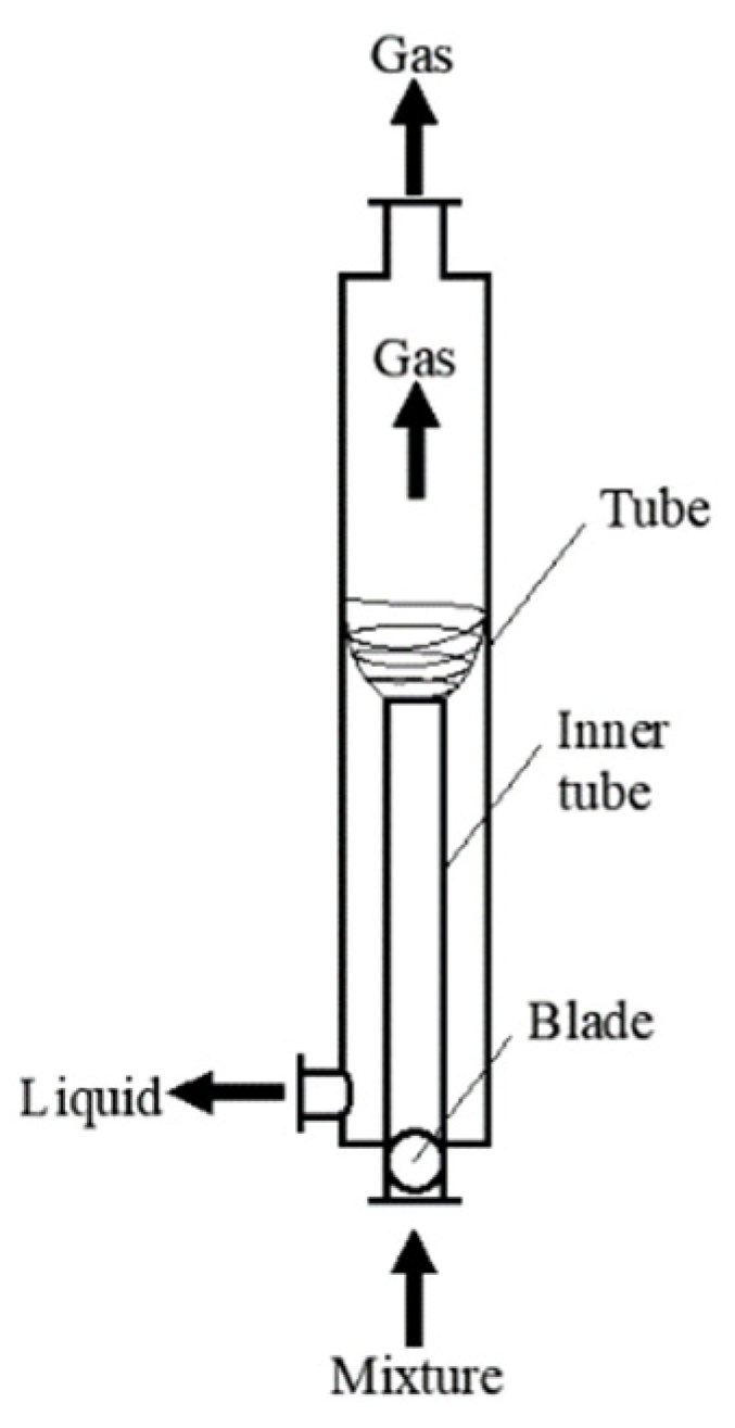
Figure 2.
Arc type guide vane.

Figure 3.
Axial flow gas-liquid separator mesh.

Figure 4.
Liquid Volume Fraction Distributions with Different Number of Grids.

Figure 5.
Separator experiment flow diagram.

Figure 6.
Experimental Loop Diagram.

Figure 7.
Comparison of experimental and simulated values.

Figure 8.
Separator internal liquid phase distribution.

Figure 9.
Liquid phase distribution in different positions of separator inner cylinder.
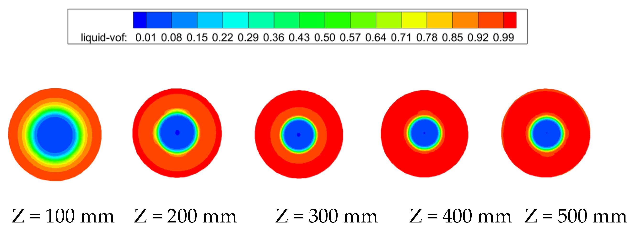
Figure 10.
Radial distribution of liquid volume fraction at different positions in the inner cylinder.
Figure 10.
Radial distribution of liquid volume fraction at different positions in the inner cylinder.

Figure 11.
Internal axial velocity distribution of the separator.

Figure 12.
Separator inner cylinder axial velocity distribution at different locations.

Figure 13.
Radial distribution of axial velocity at different positions in the inner cylinder. (a) Axial velocity distribution at different positions (within 50 mm); (b) Axial velocity distribution at different positions (more than 100 mm).
Figure 13.
Radial distribution of axial velocity at different positions in the inner cylinder. (a) Axial velocity distribution at different positions (within 50 mm); (b) Axial velocity distribution at different positions (more than 100 mm).

Figure 14.
Separator internal tangential velocity distribution cloud.

Figure 15.
Tangential velocity distribution at different positions of inner cylinder of separator.

Figure 16.
Radial distribution of tangential velocity at different positions in the inner cylinder.

Figure 17.
Pressure changes in different positions in the inner cylinder.

Figure 18.
Guide vane pressure changes cloud map.

Publisher’s Note: MDPI stays neutral with regard to jurisdictional claims in published maps and institutional affiliations. |
© 2021 by the authors. Licensee MDPI, Basel, Switzerland. This article is an open access article distributed under the terms and conditions of the Creative Commons Attribution (CC BY) license (https://creativecommons.org/licenses/by/4.0/).
Share and Cite
MDPI and ACS Style
Kou, J.; Li, Z. Numerical Simulation of New Axial Flow Gas-Liquid Separator. Processes 2022, 10, 64. https://doi.org/10.3390/pr10010064
AMA Style
Kou J, Li Z. Numerical Simulation of New Axial Flow Gas-Liquid Separator. Processes. 2022; 10(1):64. https://doi.org/10.3390/pr10010064
Chicago/Turabian StyleKou, Jie, and Zhaoyang Li. 2022. "Numerical Simulation of New Axial Flow Gas-Liquid Separator" Processes 10, no. 1: 64. https://doi.org/10.3390/pr10010064
Note that from the first issue of 2016, this journal uses article numbers instead of page numbers. See further details here.