1. Introduction
Aluminium (Al) alloys are utilised as structural materials in a variety of industries, including automotive, aircraft, and railway. There is a necessity in the automobile engineering field to weld a earthing pin made of steel to car body made of aluminium matrix composite. Current engineering applications necessitate materials that are stronger, lighter, and less expensive. These materials should be developed with superior mechanical qualities, such as a high strength-to-weight ratio, for aerospace and automotive applications [
1,
2]. In the past, welding was used to join two metals of the same type, whereas fasteners were used to unite metals of different types. Friction stud welding is an engineering advancement that produces welds between various metals without the use of melting or fillers. Friction stud welding does not use electricity to generate heat; instead, as the name implies, friction is used. Dissimilar metal welding has drawbacks to arc welding, such as intermetallic phase types. Traditional and natural welding procedures cannot be utilised to join different metals because of this. Over the last two decades, friction welding technologies have shown promise in the welding of dissimilar metals [
3].
Several investigators used a friction welding machine to fuse dissimilar materials by altering process parameters such as rotational speed (RS), friction pressure (FP), friction time (FT), forging pressure (FGP), and forging time (FGT). Friction welding machines have been used to join titanium to nickel, bronze to steel and brass to copper, using a choice of intermediate materials as interlayers [
4]. The applicability of a friction welding machine to join Al to steel and Al to ceramic was performed, and the challenges encountered while combining these different materials were investigated [
5]. To produce a satisfactory weld quality, ceramics were welded to metals with the use of friction welding equipment by altering the different process parameters [
6]. AA 6063 and AISI 1030 steel materials were fused together using a friction stud welding machine at different process parameters, such as RS, FP, FT, FGP, and FGT. Ultrasonic testing was used to analyse the mechanical properties of the welded specimen [
7]. Al was used as an interlayer in friction stud welding of Al
2O
3 and steel. The thermomechanical phenomena were studied using a computational model based on finite elements [
8]. To join different Al and mild steel, a friction stud welding procedure was used. The process parameters were adjusted to investigate the strength of the welded specimens. The welded specimen’s strength was determined by the RS, FT, and axial shortening distance [
9].
The numerical simulation approach is particularly useful for estimating the stress fields and distribution of temperature of the friction welding process. Using finite element software, the friction stud welding of ceramic to the metal with the interlayer was numerically simulated. As a result of the increased interlayer thickness, the researchers noticed a decrease in the heat-affected zone [
10]. Some researchers examined numerical simulations of friction stud-welded dissimilar materials, such as alumina to AA 6063 and MMCs to steel joints [
11,
12]. The thermal fields play a critical role in obtaining a satisfactory welded specimen during the friction stud welding procedure. Using finite element methods, a heat flow model of Al and mild steel during friction stud welding was created [
13,
14,
15,
16]. Because of the larger plastic deformation throughout the procedure, mechanical properties are affected and microhardness at the interface increases. Microstructural investigation shows dynamically recrystallized grains closer to the interfacial area [
17]. Raturi et al. investigated the FSW of 6061-T6 Al and 7075-T651 Al alloys [
18]. Tensile failure of the joints was detected from the base metal of the advancing side, according to the researchers (AA6061-T6). Furthermore, with a scanning electron microscopy examination the presence of multiple dimples was revealed in the fracture surfaces, indicating ductile failure of the joints subject to tensile loading. The influence of tool offset and material location during FSW of AA6061-T6 and AA7075-T6 alloys was investigated by Cole et al. [
19]. They found that putting the AA7075-T6 on the retreating side with the tool offset into the retreating side raised the tensile strength of the joined specimen because the amount of AA7075 alloy in the welded nugget was increased. In an experiment using the finite element approach, Tang and Shen investigated the influence of preheating with an electric arc heater on material flow and temperature distribution during FSW between Al alloy and steel by experimental and numerical approaches [
20]. They claim that preheating minimises the temperature difference between the welded material, which increases material flow and strength. Friction stir welding, according to Ji et al. was beneficial in improving the mixing degree of Mg/Al alloys and breaking partial IMCs into particles, thereby boosting joint strength [
21]. Zinc was introduced as a buffer at the interface to enhance the desirable mechanical properties [
22]. Hynes et al. joined AA6061 to MgAZ31 B in an in-house modified milling machine by changing the offset [
23]. The presence of oxygen and unwanted inclusions were noticed [
24,
25,
26]. Such findings were further reported as well [
27,
28]. Interlayers were employed to overcome challenges such as oxygen inclusion in the interfacial region [
29,
30,
31,
32,
33]. Seli et al. [
34] investigated the friction welding of Al
2O
3–steel, using an Al interlayer and found the effect of interlayers keeping the rotational speed constant.
Oxidization quickly occurs when fusion welding is conducted in a natural environment and can contribute to both slag inclusion and porosity in the weld, which will significantly reduce its intensity. In order to overcome these issues, we have to eliminate the presence of oxygen by coating the solder pool with an inert gas. Inert gases such as argon or nitrogen may be used for this. In this work, argon gas was used as the shielding gas. The application of an inert atmospheric shield would increase the consistency of the weld and enhance the deposit’s properties.
2. Materials and Methods
2.1. Selection of Materials
The aluminium 6061 alloys are mainly used in the application of the automobile and aeronautical industries. Due to its good strength, lightweight and better corrosion properties, 6061-T6 aluminium alloy (AA) is commonly used in aircraft, protection, automobiles and marine areas. AA6061 is a heat-treatable alloy of medium-to-high strength. While it has decreased strength in the weld region, it has very good corrosion resistance and very good weldability. It has medium strength for fatigue. In rail coaches, truck frames, shipbuilding, bridges, and military bridges, and aerospace applications such as helicopter rotor skins, tubes, pylons and towers, transport, rivets and motorboats, AA6061 is usually used for heavy-duty structures.
Table 1 and
Table 2 list the chemical composition and mechanical properties of AA6061 in a normal atmosphere.
Boron carbide (B
4C) ranks third behind diamond and cubic B
4C as one of the hardest materials known. It is the hardest material produced in terms of tonnage. B
4C powder is used as an abrasive in polishing and lapping applications because of its elevated hardness, and also as a loose abrasive in cutting applications such as water jet cutting. It can also be used on diamond equipment for dressing. Ceramic tooling dies, precision toll components, evaporating boats for measuring materials, mortars and pestles are other applications. The AA6061 reinforced with B
4C is shown in
Table 3 and the properties of B
4C are shown in
Table 4 in a normal atmosphere.
AISI 1030 steel is known as medium-carbon steel, and in the as-rolled state, has moderate strength and hardness. Via cold practice, it can be hardened and reinforced. It has decent machinability, ductility and reasonable potential for welding as well. For manufacturing machinery components, AISI 1030 carbon steel is suitable. The chemical compositions and mechanical properties of AISI 1030 steel in a normal atmosphere is shown in
Table 5 and
Table 6.
2.2. Friction Stud Welding Machine
The friction stud welding system was developed in the present work by modifying the standard lathe for a general purpose (Type A141, PSG, Coimbatore, India). The main modifications made were the installation of an effective braking system and replacement of compound rest by stud-holder assembly. Welding time, rigid clamping, axial strength, forging pressure and immediate stopping of the spinning object are the essential parameters influencing friction stud welding.
2.3. Friction Stud Welding in an Inert Gas Atmosphere
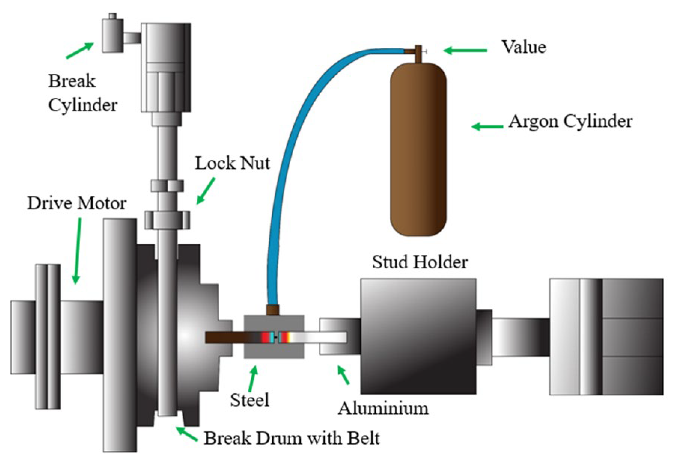
In the friction stud welding unit, the schematic representation of argon shielding is shown in
Figure 1. This fabricated friction stud welding machine was developed through certain modifications performed on a lathe. Welding time, rigid clamping, axial strength, forging pressure and instant stopping of moving artefacts are the critical parameters involved in friction stud welding. Thus, an effective brake device was arranged by means of a simple band brake for instant stopping of the spinning object kept in the chuck. A belt was wound around the brake drum, whose one side was attached to a fixed end and the other side was attached to a movable end. The fixed end was the slacking side and the movable end was the tight side. A lever arrangement was provided to apply less effort while actuating the brake. Using a limit switch, the motor power is cut off simultaneously while the brake lever is actuated.
A pneumatic circuit was introduced to deliver uniform axial and forging pressures to the stud against the rotating object in the chuck. For rigid clamping of the stud, a stud holder was fabricated. The stud was screwed into a Morse taper which was fitted in the front end of the stud holder. The front end of the stud holder was machined to suit the Morse taper. The rear end of the stud holder was machined to suit the rod end of the pneumatic cylinder. At the bottom of the stud holder, two holes were drilled and tapped so that it was fastened to the sliding plate with bolts. The sliding plate slides in the guideways. The guideways were fastened to a base plate by means of four Allen screws. The base plate which contains the stud holder assembly and the pneumatic cylinder replaced the compound rest of the lathe. The process parameters were controlled using a programmable logic controller.
2.3.1. Experimental Arrangement for Friction Stud Welding in an Inert Gas Atmosphere
In this work, argon gas was used as the shielding gas. The experimental arrangement for friction stud welding in an inert gas environment is shown in
Figure 2.
2.3.2. Preparation of Specimen
Experiments were performed on a direct drive friction stud welding system mounted on a programmable logic controller.
Figure 1 shows the schematic representation of the structure for friction stud welding. By machining AISI 1030 steel rods up to 12 mm in diameter and 45 mm in length, samples of AISI 1030 steel were prepared. AA 6061 stud samples of equal diameter and length, with a 1.75 mm thread as a pitch, were prepared as shown in
Figure 3. The successful friction stud welded AA 6063/AISI 1030 joints are shown in
Figure 4. To carry out microstructural analysis, friction stud welded joints were cut vertically to the surface of the joint. Mechanical polishing was then done with different grades of emery papers. Then, they were etched with ferric chloride solution. The specimens prepared for microhardness determination and microstructural analysis are shown in
Figure 5.
2.4. Plan of Experiments
In order to analyse the effect of argon shielding, processing conditions such as rotational speed, friction time, and friction pressure were taken into consideration. During the experimentation, friction time and friction pressure were retained, while the rotational speed was varied: 800, 1150 and 1600 rpm. At first, experimental runs were conducted under normal conditions that were without shielding. Afterwards, the experimental runs were repeated with argon shielding in an inert atmosphere. These experimental plans are tabulated in
Table 7.
2.5. Mechanical Testing and Microstructural Analysis Testing
Mechanical testing was conducted in order to assess the impact strength of the welded joints. Using the Charpy effect measurement device, this was carried out at room temperature. Impact test samples measuring 10 × 7.5 × 50 mm were prepared with a 2 mm deep ‘V’ notch and a 450 groove in line with the ASTM A370 requirements. The specimen perpendicular section was made to the weld surface for microstructural inspection, and mechanical polishing was performed using emery papers accompanied by ferric chloride solution etching.
Using SEM (Hitachi, SU1510—Chiyoda City, Japan), EDX analysis, and microhardness measurement for microstructural evaluation, the prepared specimen was investigated. The Vickers hardness tester was used in order to measure the microhardness variations across the welded joint. Indents were made for a load of 5 kg and a holding time of 20 s on the welded specimen. The indenter was then removed from the surface of the sample and used to calculate the indentation dimensions using an optical microscope.


 ,
, 


