
Research on the Influence of a Cuttings Bed on Drill String Friction Torque in Horizontal Well Sections
by
Xiaoming Li
1,
Yuyue Fan
1,
Jiahua Li
2,*,
Xinghua Su
1,
Sheng Zhan
1,
Gang Hu
1,
Yiqing He
1 and
Ming Zhang
2 1
CNPC Chuanqing Drilling Engineering Company Limited, Xi’an 710018, China
2
School of Petroleum Engineering, Xi’an Shiyou University, Xi’an 710065, China
*
Author to whom correspondence should be addressed.
Processes 2022, 10(10), 2061; https://doi.org/10.3390/pr10102061
Submission received: 13 September 2022
/
Revised: 8 October 2022
/
Accepted: 9 October 2022
/
Published: 12 October 2022
(This article belongs to the Special Issue Natural Gas Hydrate Production Technology and Rock Mechanics in Petroleum Engineering)
Abstract
:Horizontal well drills are difficult to operate and require high borehole cleaning operations. The impact of cuttings accumulation on friction and torque cannot be ignored. In the process of horizontal well drilling, it is very easy to form a cuttings bed in the highly inclined eccentric annulus. The formation of the cuttings bed will not only increase the friction torque but also have a greater impact on the annulus flow. Based on the application of gas drilling in horizontal wells, this paper uses laboratory experiments to study the influence of cuttings with different particle sizes and lithology on the friction coefficient between the drill string and the borehole wall of the horizontal well section. In addition, in view of the difficulty in the migration of cuttings in gas drilling horizontal wells and the formation of cuttings deposits, this paper carries out an experimental study on the effect of the cuttings bed on drill pipe coating height and cuttings bed thickness on friction coefficient. Experimental results show that the friction coefficient of gas drilling horizontal wells is about 0.44–0.58. When the coating height of the cuttings on the drill pipe exceeds a certain value (26 mm), the friction coefficient tends to be stable, but its value is as high as about 0.55. When the thickness of the accumulation of cuttings exceeds a certain value (10 mm), the subsidence hindering effect between the particles in the cuttings bed is weakened, so the friction coefficient of the casing section and the open hole section tends to be stable, about 0.53.
1. Introduction
In drilling, the borehole is usually not completely vertical. There is contact pressure between the drill string and the borehole wall. When the drill string moves, due to friction, it will exert axial resistance and rotational torque on the drill string, increasing the load and rotational torque [1]. Especially in extended-reach wells and horizontal wells, due to the characteristics of long horizontal displacement sections, large well inclination angles, and long open-hole stabilizing sections, there is great friction and torque. Drilling friction, refers to the frictional resistance between the pipe string and the borehole wall during the drilling process, which is mainly composed of the sliding frictional resistance of the drill string and the rolling frictional torque [2,3]. Axial frictional resistance is the frictional resistance generated when the drill string moves along the drilling direction, and it is a key factor affecting the drill string’s drop-in and extension ability [4,5].
In 1984, a soft rod model for predicting the tension and torque of the drill string during directional well drilling was first proposed [6]. In 1988, based on the theory of large deformation, some scholars improved the frictional resistance and considered the effect of rod string stiffness on the drill string [7]. Analysis shows that the soft rod model is suitable for the case where the borehole curvature is small, while the steel rod model is suitable for the case where the borehole curvature is large. Their research work laid the theoretical foundation for follow-up scholars to carry out related friction research. In 1991, some scholars discussed the influence of borehole structure, borehole deformation, and drill cuttings adhesion on the friction between the drill string and borehole wall and for the first time applied the finite element method to the drilling friction solution process [8].
In 2009, some scholars systematically analyzed the influencing factors and influence laws of drilling fluid aggravating agents on friction [9]. The research results show that the drilling fluid has a critical weighted density. Before reaching this density, as the drilling fluid density increases, the friction coefficient of the formed mud cake increases, and the lubrication performance of the drilling fluid decreases [10]. When the critical density is exceeded, the lubrication performance increases. In 2015, some scholars adopted the finite element method and established a new dynamic friction and torque calculation model based on the dynamic model of the three-dimensional nonlinear drill string system of highly deviated well [11,12]. Effective analysis and prediction of resistance well types are of great guiding significance for field operations.
This paper takes the sliding friction coefficient as the main object and gas drilling horizontal well as the engineering background. It is reasonable to establish an indoor experimental platform for measuring the axial friction coefficient of horizontal well sections to determine the axial friction coefficient of the drill string under different cuttings bed conditions.
2. Materials and Methods
2.1. Experimental Plan Design
In the horizontal section, the drill string lies flat on the bottom wall of the borehole under the action of its own gravity [13,14]. At the same time, due to the combined action of the weight on the bit and the torque, the horizontal section of the drill string is bent or even spirally bent. In this experiment, only the pressure exerted by the weight of the drill string on the lower wall of the borehole was considered, and the force exerted by factors such as drill string bending on the lower wall of the borehole was ignored [15,16]. Assuming that the drill pipe is advancing at a constant speed in the wellbore, it is characterized by the classical friction calculation formula. The friction resistance of the drill pipe is proportional to the positive pressure between the drill pipe and the borehole wall, namely:
f is the friction resistance, F is the positive pressure of the drill pipe against the lower wall of the borehole, and p is the friction coefficient. The friction coefficient is related to the contact surface material, the roughness of the contact surface and other factors, and is also affected by the lubricating medium between the drill pipe and the borehole wall. In this experiment, the dry cuttings particles under gas drilling conditions and the mixture of cuttings with different particle sizes and different density drilling fluids under mud drilling conditions are set as different lubricating media [17]. The experiment calculates the friction coefficient of the contact surface by measuring the gravity of the drill rod and the drag force f when the drill rod is dragged at a constant speed.
This experiment focuses on analyzing the influence of lubricating medium on the coefficient of friction [18]. The experiment is mainly carried out from the following three aspects:
① According to the characteristics of air drilling, the lubricating medium in this experiment is divided into the following categories: dry friction (no cuttings) and cuttings (different particle size, mixed particle size).
② According to the different borehole conditions, the experimental well section is divided into casing section and open hole section.
③ In order to analyze the influence of lithology on the friction coefficient, two types of cuttings with different lithologies are obtained from two layers (3400–3800 m and 4500–4800 m).
Aiming at the friction coefficient measurement method adopted, the experimental platform design scheme is established. In Figure 1, the drill pipe and the well wall form a set of friction pairs, and the drill pipe is dragged under the action of the axial traction force of the power mechanism. The sensor installed on the connecting power mechanism and the drill rod beam is used to measure the drag force when the drill rod is dragged at a constant speed. The output of the sensor is a voltage signal that is converted, collected, and sorted by the data acquisition system to obtain the true traction value.
2.2. Preparation of Experimental Samples
During the drilling process, the wall surface in contact with the drill string is divided into the wall of the open hole rock and the inner wall of the casing. Due to the different materials of the rock and the casing, the friction coefficient of the friction pair formed with the drill string is also different, so the friction resistance generated is also different. In order to comprehensively analyze the frictional resistance of the drill string during drilling, the experiment tests two friction pairs of drill string-open hole and drill string-casing. Today, horizontal wells often adopt a two-layer casing structure. After the surface casing is installed, the φ216 mm wellbore is drilled directly to the bottom of the well. Therefore, the open hole size is φ216 mm. A 7” (φ179.9 mm) casing is commonly used in the φ216 mm wellbore, and the casing size is small. It is inconvenient to install and adjust the position of the drill pipe in the experiment. Therefore, 9 5/8” (φ 244.5 mm) is used.
2.3. Preparation of Open-Hole Rock Samples
The open-hole rock sample is obtained from the rock surface outcrop. The open-hole rock sample is prepared using a sandstone with a length, width, and height of 400 mm × 400 mm × 400 mm. A roller cone bit is used to drill a 216 mm diameter wellbore on the rock sample, and a stone cutter is used to cut a long, wide, and high 310 mm × 310 mm × 240 mm rock sample to prepare 3 open-hole rock samples. When preparing rock samples, it is necessary to ensure that when all rock samples are based on the bottom surface of a certain well circumference, the pilot boreholes are kept coaxial and the upper and lower end faces are perpendicular to the borehole axis.
2.4. Cuttings Collection and Classification
The cuttings are collected in a gas drilling well at a depth of 3400–3800 m and 4500–4800 m. The collected cuttings are divided into <l mm, 1 mm, 2 mm, 3 mm and >4 mm according to the particle size. After analyzing the logging parameters, it is found that the slant depth of 3400 to 3800 m belongs to the first layer of the east section. The rock composition of this section is light gray fine sandstone, gray mudstone, gray-green mudstone, and gray siltstone. The oblique depth of 4500–4800 m belongs to the third layer of the east. The rock composition of this layer is dark gray mudstone, gray argillaceous siltstone, light gray siltstone, gray brown mudstone, gray fine sandstone, gray conglomerate sandstone, among which the mudstone content is high. After sieving the cuttings samples obtained from the two intervals, it is found that among the cuttings obtained from the 3400–3800 interval, cuttings with particle sizes of <l mm, 1 mm, and 2 mm are the main components in the samples. The content of cuttings of the particle size around 3 mm is relatively small, accounting for nearly 10% of the total, while the content of cuttings with a particle size larger than 4 mm is less than 1% of the total amount of cuttings samples. Among the core samples obtained from the 4500–4800 interval, the content of cuttings with a particle size of <1 mm, 1 mm and 2 mm is the largest, accounting for 80% of the total cutting samples, while the content of the cuttings with particle size larger than 4 mm is still less than the 10% of total cuttings.
3. Results
3.1. Experimental Study on Friction Coefficient between Casing Section and Open Hole Section of Gas Drilling Horizontal Well
3.1.1. Experimental Study on the Influence of Cuttings Size and Lithology on Friction Coefficient under Open-Hole Conditions
When using gas to drill a horizontal well, if there is no cuttings deposition, the horizontal section of the drill string is in direct contact with the open-hole rock wall. When cuttings accumulation occurs on the lower wall of the horizontal section of the wellbore, the drill pipe presses on the cuttings layer. At this time, the cuttings act as a lubricating medium between the drill string and the borehole wall. Experiments are carried out after cuttings are laid on the lower wall of the borehole to measure the friction resistance under different cuttings particle size conditions. This paper studies the friction coefficient of drill string under two different lithology, particle size, and mixed cuttings conditions in the 3400–3800 m interval and the 4500–4800 m interval. The cuttings are taken from the sample well during drilling in the target section. The open hole section consists of two rock samples, with a total length of 480 mm, a total length of 700 mm of drill pipe, and an experimental drag distance of 200 mm. Therefore, during the entire experiment, the center of gravity of the drill pipe is always in the wellbore, which meets the requirements of experimental principles. We adjust the slide box, sensor and drill string to the initial position of the experiment and adjust the drill string to ensure that the cross beam is level with the table top of the experiment table. Then, we start the machine tool, and the tool holder drags the drill forward at a constant speed. According to the calculation of the feed gear of the machine tool, when the spindle speed of the machine tool is 77 r/min and the auxiliary handle of the feed box is switched to the B-III gear, the actual longitudinal feed speed of the skateboard box is 19.8 m/h, which is in line with the conventional ROP. Taking cuttings with a particle diameter of 3 mm as an example, the experimental results are shown in Table 1.
3.1.2. Experimental Study on the Influence of Cuttings Size and Lithology on Friction Coefficient under Casing Conditions
For gas drilling horizontal wells, the frictional resistance between the drill string and the casing in the horizontal section and the frictional resistance under different lubricating media conditions are measured using the drill string tubing experimental platform. The total length of the casing is 500 mm, the drill string is 700 mm, and the experimental drag distance is 200 mm. During the entire experiment, the center of gravity of the drill pipe is always in the casing, which meets the requirements of the experimental principle. We adjust the slide box, sensor, and drill string to the initial position of the experiment, and we adjust the drill string to ensure that the cross beam is level with the table top of the experiment table. We start the machine tool and drag the drill rod 200 mm forward at a constant speed to reach the end of the experiment. We complete the determination of the friction resistance of the horizontal casing section of gas drilling under different lubricating medium conditions (no cuttings, different particle size cuttings, different cuttings coating height, different cuttings layer thickness and mixed cuttings), and complete the corresponding data records. The experimental results are shown in Table 2.
It can be seen from the table that for the cased section of the 3400–3800 interval, when the particle size of the cuttings is less than 1 mm, the friction coefficient reaches the maximum. When the particle size of the cuttings is 1 mm to 3 mm, the friction coefficient increases with the particle size of the cuttings. When the particle size is greater than 4 mm, the friction coefficient appears to decrease. In the casing section, when the particle size is 2 mm, the friction coefficient increases continuously with the increase of the particle size. When the cuttings particle size is 2 mm, the friction coefficient drops significantly, reaching the minimum value of 0.43. The main reason for this change in friction coefficient is determined by two major factors: cuttings and wellbore conditions.
Compared with the macroscopically large size of experimental drill pipes, rocks, and casings, cuttings with a particle size of less than 1 mm can be approximated as extremely tiny spherical particles. During the experiment, cuttings are laid evenly and in a single layer on the lower wall of the borehole. Therefore, for the rough, open-hole rock wall of the borehole, tiny spherical particles are filled in the pits on the wall of the borehole. The impact of the rock shaft wall contact side is very small. The drill pipe is in direct contact with the open hole rock wall, so the friction coefficient is relatively large. As the particle size of the cuttings increases, the geometrical size characteristics of the cuttings begin to become prominent. As a special lubricating medium, the drill pipe and open hole rock wall contact pair are isolated. When the drill pipe is dragged, rolling occurs.
When the particle size of the cuttings is small (l mm), the cuttings roll easily. At this time, the friction coefficient reaches the minimum. As the particle size increases, the geometric irregularities of the cuttings begin to take effect, hindering the rolling of the cuttings or increasing the difficulty of sliding. Therefore, the friction coefficient increases. Since the casing section has a smooth metallic inner wall, tiny spherical particles (<l mm) can also roll more easily, which can better exert the “lubricating” characteristics, and the friction coefficient is minimized at this time. Similarly, the geometric irregularity of cuttings becomes more prominent with the increase of the particle size of cuttings, resulting in a continuous increase in the friction coefficient.
Both the open hole section and casing section of the 4500–4800 interval show a trend that the friction coefficient increases with the increase of the particle size. When the particle size is 2 mm, the friction coefficient reaches the minimum. The friction coefficient of the casing section is higher than that of the open-hole section as a whole. This trend of change is mainly due to the fact that the rocks in this section are mainly sandstone and mudstone with a high content of mudstone. When the particle size of the cuttings is small, due to the low strength of the mudstone, the mudstone particles in the cuttings are directly crushed by the drill pipe, and the increased sandstone particles may also be crushed.
At this time, the micro-convex structure of the drill pipe and the casing surface can be in direct contact, and adhesion is likely to occur under the action of the load. According to the sliding friction mechanism, when sliding occurs, shearing action occurs between the contact points of the metal contact pair. To overcome the adhesion on the actual contact surface requires a larger frictional energy (friction force), therefore, the friction coefficient is larger. With the increase in the particle size, although the cuttings will be crushed, the load bearing capacity is improved. The drill pipe and the casing are not in direct contact, so the friction coefficient is reduced.
The geometric irregularities of cuttings begin to become prominent with increases in the cuttings’ particle size, and the friction coefficient shows an increasing trend. Under the condition of no cuttings, the friction coefficient is measured when the drill pipe is in direct contact with the open hole rock well wall and the casing. The contact pair between the drill pipe and the casing belongs to the metal contact pair. The open-hole rock wall is in hard and soft contact. This result also confirms that the micro-convex structure on the casing has a stronger ability to hinder the slide of the drill pipe than the open-hole rock wall. In summary, for this formation section, the friction coefficient of the casing section is greater than that of the open-hole section.
3.2. Experimental Study on the Influence of Cuttings Deposition on the Friction Coefficient of the Horizontal Section of a Gas Drilling Horizontal Well
3.2.1. Deposition Characteristics of Cuttings in Horizontal Section and Analysis of Drill String “Coating Effect”
In the actual drilling process, cuttings of a certain grain size will be deposited on the wall of the horizontal borehole under the action of gravity, and then form a cuttings bed. In the same way, even if the horizontal section of the drill pipe is subjected to tensile and torsion loads, it will still lie down on the wall of the well under the action of gravity and will first come into contact with the cuttings bed. The cuttings bed is formed by the accumulation of many single cuttings. Without considering the formation of water, the particles remove the subsidence constraints between each other and the frictional resistance between each other. Therefore, the cuttings bed can be regarded as loose particles with a certain bearing capacity. When the drill string is pressed on it, it will gradually intrude into the cuttings bed. The horizontal section of the drill pipe is partially covered by the cuttings bed accumulated on the bottom wall.
After the cuttings bed coats the drill pipe, the resistance of the surface rock cuttings in contact with the drill pipe to the axial movement of the drill pipe is realized by the subsidence constraint between the cuttings in the lower layer and is transmitted down to the borehole wall layer by layer, which shows that the frictional resistance of the drill pipe under the condition of cuttings coating is directly related to the nominal contact area of cuttings and the thickness of the cuttings bed. The nominal contact area is mainly determined by the outer diameter of the drill string and the weight of the drill string. Since the same drill pipe sample is used in the experiment, the nominal contact area is basically unchanged when it is laminated on the cuttings bed. In order to simulate the influence of the contact area and the thickness of the cuttings bed on the friction coefficient, the experiment is achieved by artificially adjusting the coating height of the drill string and the thickness of the accumulation.
3.2.2. Experimental Study on the Influence of Cuttings “Coating Effect” on Friction Coefficient
Taking the cuttings with a particle size of 2 mm as the experimental object, the friction resistance of the drill pipe under the conditions of different accumulation thicknesses of cuttings and different coating heights of cuttings on the drill pipe is carried out. The different accumulation thickness of cuttings is the actual height of cuttings accumulated on the lower well. Three cuttings accumulation thicknesses, 5 mm, 10 mm, and 15 mm, are set in the experiment. Different coating heights of the cuttings on the drill pipe means that cuttings accumulate along the gap between the drill pipe and the borehole wall to form a coating on the drill pipe. In the experiment, three types of cuttings with the height value of “17 mm, 26 mm and 33 mm” are set for the drill pipe. The coating heights of the experimental group are shown in Table 3 and Table 4.
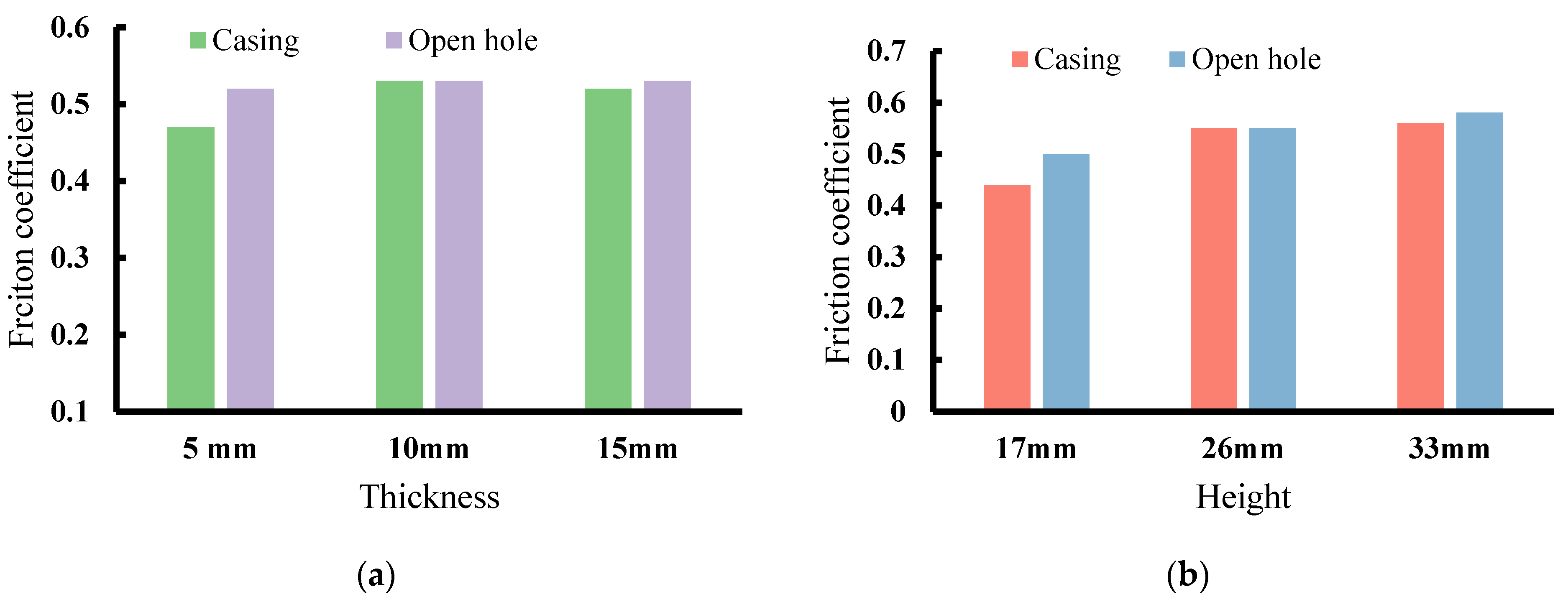
Under actual drilling conditions, the cuttings will form a certain thickness of accumulation on the lower wall of the borehole, and the drill pipe will press on it, so the cuttings will form a certain coating on the drill pipe. If the sliding drilling operation method is adopted, this coating trend will be more obvious. Figure 2 analyzes the influence of different cuttings thickness and cuttings coating on drill pipe friction.
It can be seen from the figure that the friction coefficient of the casing section and the open hole section presents an opposite trend with the change of the thickness of the accumulation: The friction coefficient of the open-hole section decreases with the increase in the accumulation thickness of cuttings. This change trend is mainly due to the increase in the thickness of the fixed cuttings layer near the borehole wall due to the rough borehole of the open-hole section. However, when the thickness of cuttings accumulation exceeds a certain value (critical value −10 mm), the hindering effect of subsidence between the particles in the experimental loose cuttings bed is weakened, and the friction coefficient of the casing section and the open hole section tends to be stable, about 0.53. At this time, the thickness of the accumulation has fully met the thickness required for relative sliding. According to the change trend shown in the figure, in the actual drilling process, the well structure and depth should be integrated, the thickness of cuttings accumulation should be reasonably controlled, and the frictional resistance of the entire well section should be reduced.
For the open hole section, the friction coefficient of the drill pipe increases with the increase in the coating height of the drill pipe by the cuttings. As for the casing section, when the cuttings coating height exceeds a certain value (26 mm), the friction coefficient decreases slightly and tends to be approximately stable, about 0.55. Compared with accumulation, cladding provides a larger contact area between cuttings and the drill pipe and increases the friction of the drill pipe. Compared with the rough inner wall of the open hole rock wall, the inner wall of the casing is smoother, so the cuttings covering the drill pipe have a stronger ability to relatively slip when the drill pipe is dragged. However, in general, when the cuttings coat the drill pipe, the friction coefficient of the drill pipe is relatively high. During the actual drilling process, the coating of the drill pipe by the cuttings should be minimized.
4. Conclusions
(1) Using the method of laboratory experiment, the influence of cuttings of different particle size and lithology on the friction coefficient between the drill string and the borehole wall of the horizontal well section is studied. According to the experimental results, the friction coefficient of gas drilling horizontal well is about 0.44–0.58. The experimental results show that due to the rough surface of the inner wall of the borehole in the open hole section, small particles (less than 1 mm) are easy to fill in the pits on the borehole wall, which has minimal impact on the contact between the drill pipe and the open hole rock wall. The inner wall of the casing is smooth, the micro-particle cuttings are more prone to rolling, showing a smaller friction coefficient. The geometric size characteristics of cuttings begin to become prominent with the increase in particle size, which can isolate the contact between the drill pipe and the borehole wall, which reduces the frictional resistance. With the further increase of the particle size of the cuttings, the irregular characteristics of the cuttings begin to play a role, hindering the rolling of the cuttings, which is manifested as an increase in the friction coefficient. The cuttings with high lithological strength have strong bearing capacity, and their friction coefficient is relatively low under the condition of the same particle size.
(2) In view of the difficulty of cuttings migration in gas drilling horizontal wells and the formation of cuttings deposition and bed formation, this paper carries out an experimental study on the effect of cuttings bed on drill pipe coating height and cuttings bed thickness on the friction coefficient. The research results show that when the coating height of cuttings on the drill pipe exceeds a certain value (26 mm), the friction coefficient tends to be stable, but its value is as high as about 0.55. In actual drilling, the impact of cuttings should be minimized. Compared with the smooth inner wall of the casing, the open hole section has an increased constraint on the cuttings layer near the borehole due to the geometric irregularity of its surface. Therefore, the friction coefficient decreases with increases in the thickness of the cuttings bed. When the thickness of the cuttings accumulation exceeds a certain value (10 mm), the subsidence barrier between the particles in the loose cuttings bed in the experiment is weakened, so the friction coefficients of the casing section and the open hole section tend to be stable, about 0.53.
(3) The friction coefficient of the gas drilling well section obtained through the laboratory experiments in this chapter belongs to the axial sliding friction coefficient that does not consider the rotation of the drill string. Compared with the actual drilling conditions, the friction coefficient is calculated using the actual torque value of the turntable. It has not comprehensively responded to the influence of factors such as the bending deformation of the downhole drill string, but it can still describe the characteristics of the friction coefficient under the conditions of gas drilling in a horizontal well.
Author Contributions
Conceptualization, X.L.; methodology, Y.F.; validation, J.L.; investigation, X.S.; resources, S.Z.; data curation, Y.H.; writing—original draft preparation, G.H.; writing—review and editing, M.Z. All authors have read and agreed to the published version of the manuscript.
Funding
This research received no external funding.
Acknowledgments
This work was supported by the Changqing Drilling Corporation project “Drilling technical support platform in Changqing zone ”.
Conflicts of Interest
The authors declare no conflict of interest.
References
- Su, Z.; Gudmundsson, J.S. Perforation inflow reduces frictional pressure loss in horizontal wellbores. J. Pet. Sci. Eng. 1998, 19, 223–232. [Google Scholar] [CrossRef]
- Miller, S.F.; Tao, J.; Shih, A.J. Friction drilling of cast metals. Int. J. Mach. Tools Manuf. 2006, 46, 1526–1535. [Google Scholar] [CrossRef]
- Miller, S.F.; Shih, A.J.; Blau, P.J. Microstructural alterations associated with friction drilling of steel, aluminum and titanium. J. Mater. Eng. Perform. 2005, 14, 647–653. [Google Scholar] [CrossRef]
- Krivtsov, A.M.; Wiercigroch, M. Penetration rate prediction for percussive drilling via dry friction model. Chaos Solitons Fractals 2000, 11, 2479–2485. [Google Scholar] [CrossRef]
- Zhang, J.; Mao, B.; Roegiers, J.C. On drilling directions for optimizing horizontal well stability using a dual-porosity poroelastic approach. J. Pet. Sci. Eng. 2006, 53, 61–76. [Google Scholar] [CrossRef]
- Yan, H.T. Geotechnical sampling in deep water using a tensioned conductor pipe-casing and weighted footblock. Can. Geotech. J. 1984, 21, 92–99. [Google Scholar] [CrossRef]
- Maidla, E.E. A field method for assessing borehole friction for directional well casing. J. Pet. Sci. Eng. 1988, 1, 323–333. [Google Scholar] [CrossRef]
- Babu, D.K.; Odeh, A.S.; Al-Khalifa, A.J.; Mccann, R.C. The relation between wellblock and wellbore pressures in numerical simulation of horizontal wells. SPE Reserv. Eng. 1991, 6, 324–328. [Google Scholar] [CrossRef]
- Scheid, C.M.; Calada, L.A.; Rocha, D.C.; Aranha, P.E.; Arago, F.L. Methodology to predict friction pressure drop in drilling fluid flows. Bol. Tec. Prod. Pet. 2009, 4, 301–316. [Google Scholar]
- Hao, X.U.; Tang, H.; Zhang, X. Long lateral-section horizontal well drilling technology in Xinchang gas field. Oil Drill. Prod. Technol. 2013, 35, 10–13. [Google Scholar]
- Zhao, J.; Chen, X.; Li, Y.; Fu, B.; Xu, W. Numerical simulation of multi-stage fracturing and optimization of perforation in a horizontal well. Pet. Explor. Dev. 2017, 44, 119–126. [Google Scholar] [CrossRef]
- Tian, Z.; Shi, L.; Qiao, L. Problems in the wellbore integrity of a shale gas horizontal well and corresponding countermeasures. Nat. Gas Ind. B 2015, 2, 522–529. [Google Scholar] [CrossRef] [Green Version]
- Zhu, X.H.; Li, K.; An, J.W. Calculation and analysis of dynamic drag and torque of horizontal well strings. Nat. Gas Ind. B 2019, 6, 183–190. [Google Scholar] [CrossRef]
- Zeng, X.; Tong, D. An improvement of the design method of optimal horizontal wellbore length. Pet. Explor. Dev. 2011, 38, 216–220. [Google Scholar]
- Tian, J.; Yang, Y.; Dai, L.; Yang, L. Dynamics and anti-friction characteristics study of horizontal drill string based on new anti-friction tool. Int. J. Green Energy 2021, 18, 720–730. [Google Scholar] [CrossRef]
- Ma, T.; Chen, P. Analysis of wellbore stability for horizontal wells in stratification shale. J. Cent. South Univ. (Sci. Technol.) 2015, 46, 1375–1383. [Google Scholar]
- Gao, G.; Miska, S.Z. Effects of boundary conditions and friction on static buckling of pipe in a horizontal well. SPE J. 2009, 14, 782–796. [Google Scholar] [CrossRef]
- Mishra, B.; Berne, B.J. Hydrodynamic calculation of the frequency dependent friction on the bond of a diatomic molecule. J. Chem. Phys. 1995, 103, 1160–1174. [Google Scholar] [CrossRef]
Figure 1.
Experimental platform scheme.
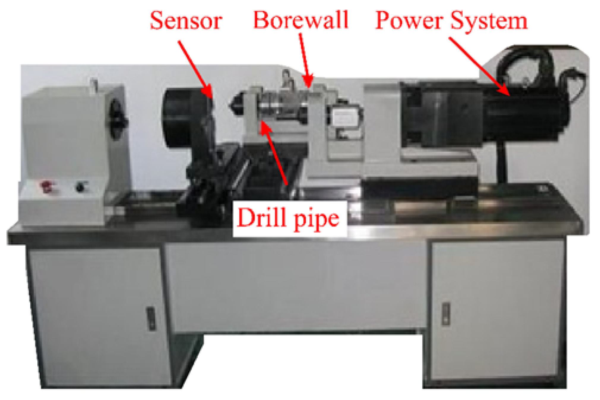
Figure 2.
Determination of friction coefficient of drill pipe under different cuttings thickness and cuttings coating height conditions. (a) at different thicknesses. (b) at different heights.
Figure 2.
Determination of friction coefficient of drill pipe under different cuttings thickness and cuttings coating height conditions. (a) at different thicknesses. (b) at different heights.

Table 1.
Friction coefficient under open-hole rock wall.
| Cutting Particle Size | 3400–3800 | 4500–4800 |
|---|---|---|
| <l mm | 0.55 | 0.56 |
| 1 mm | 0.53 | 0.55 |
| 2 mm | 0.51 | 0.57 |
| 3 mm | 0.51 | 0.56 |
| >4 mm | 0.57 | 0.53 |
| Mixed cuttings | 0.54 | 0.52 |
| No cuttings | 0.62 | |
Table 2.
Coefficient of friction under casing conditions.
| Cutting Particle Size | 3400–3800 | 4500–4800 |
|---|---|---|
| <1 mm | 0.48 | 0.58 |
| 1 mm | 0.50 | 0.50 |
| 2 mm | 0.43 | 0.51 |
| 3 mm | 0.59 | 0.59 |
| >4 mm | 0.56 | 0.56 |
| Mixed cuttings | 0.60 | 0.61 |
| No cuttings | 0.79 | |
Table 3.
Influence of different accumulation thickness of cuttings on friction coefficient.
| Thickness | 5 mm | 10 mm | 15 mm |
|---|---|---|---|
| Casing | 0.47 | 0.53 | 0.52 |
| Open-hole | 0.52 | 0.53 | 0.53 |
Table 4.
The influence of cuttings on the friction coefficient of drill pipe with different coating heights.
Table 4.
The influence of cuttings on the friction coefficient of drill pipe with different coating heights.
| Height | 17 mm | 26 mm | 33 mm |
|---|---|---|---|
| Casing | 0.44 | 0.55 | 0.56 |
| Open-hole | 0.50 | 0.55 | 0.58 |
Publisher’s Note: MDPI stays neutral with regard to jurisdictional claims in published maps and institutional affiliations. |
© 2022 by the authors. Licensee MDPI, Basel, Switzerland. This article is an open access article distributed under the terms and conditions of the Creative Commons Attribution (CC BY) license (https://creativecommons.org/licenses/by/4.0/).
Share and Cite
MDPI and ACS Style
Li, X.; Fan, Y.; Li, J.; Su, X.; Zhan, S.; Hu, G.; He, Y.; Zhang, M. Research on the Influence of a Cuttings Bed on Drill String Friction Torque in Horizontal Well Sections. Processes 2022, 10, 2061. https://doi.org/10.3390/pr10102061
AMA Style
Li X, Fan Y, Li J, Su X, Zhan S, Hu G, He Y, Zhang M. Research on the Influence of a Cuttings Bed on Drill String Friction Torque in Horizontal Well Sections. Processes. 2022; 10(10):2061. https://doi.org/10.3390/pr10102061
Chicago/Turabian StyleLi, Xiaoming, Yuyue Fan, Jiahua Li, Xinghua Su, Sheng Zhan, Gang Hu, Yiqing He, and Ming Zhang. 2022. "Research on the Influence of a Cuttings Bed on Drill String Friction Torque in Horizontal Well Sections" Processes 10, no. 10: 2061. https://doi.org/10.3390/pr10102061
Note that from the first issue of 2016, this journal uses article numbers instead of page numbers. See further details here.