
Aluminium-Assisted Alloying of Carbon Steel in Submerged Arc Welding with Al-Cr-Ni Unconstrained Metal Powders: Thermodynamic Interpretation of Gas Reactions


Abstract
:1. Introduction
2. Materials and Methods
2.1. Welding Tests
2.2. Materials and Analyses

| %C | %Si | %Mn | %O | %Al | %P | %S | %Ti | %Cu | %Cr | Balance | |
|---|---|---|---|---|---|---|---|---|---|---|---|
| Plate | 0.120 | 0.155 | 1.340 | 0.0007 | 0.067 | 0.019 | 0.007 | 0.005 | 0.030 | 0.160 | Fe |
| Wire | 0.110 | 0.137 | 0.990 | 0.0003 | 0.000 | 0.009 | 0.023 | 0.000 | 0.140 | 0.000 | Fe |
| MnO | CaO | SiO2 | Al2O3 | CaF2 | MgO | FeO | TiO2 | Na2O | K2O |
|---|---|---|---|---|---|---|---|---|---|
| 6.8 | 0.1 | 19.6 | 24.9 | 17.9 | 22.2 | 2.4 | 1.0 | 1.6 | 0.2 |
2.3. Thermochemical Calculations
3. Results
3.1. Chemical Analyses
3.2. Mass Balance
3.3. Exothermic Reactions Quantified
4. Discussion
4.1. Thermodynamics of Gas Phase Reactions

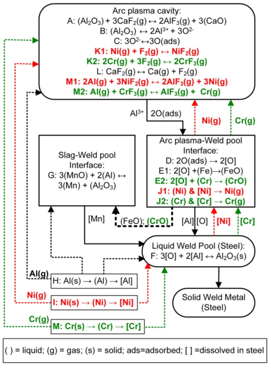
4.2. Reaction Flow Diagram with Gas Reactions
5. Conclusions
- The application of unconstrained Al, Cr, and Ni metal powders in SAW result in improved chromium and nickel yields to the weld metal. Chromium and nickel yield values achieved here with aluminium additions are higher than the literature’s reported values achieved with pre-alloyed iron-chromium-nickel powders.
- Carbon steel weld metal was alloyed with unconstrained metal powders to 6.2% Ni, 6.0% Cr, and 4.5% Al to achieve a 91% Ni yield, 89% Cr yield, and 67% Al yield to the weld metal.
- It was confirmed that the aluminium powder added into the SAW process was performed effectively to sufficiently control the oxygen potential at the molten flux–weld pool interface, without interfering with oxygen transfer from the arc plasma to the weld pool. The weld metal total oxygen content was controlled to 162 ppm O in MP8 weld metal vs. 499 ppm O in the weld metal formed in the absence of metal powder additions.
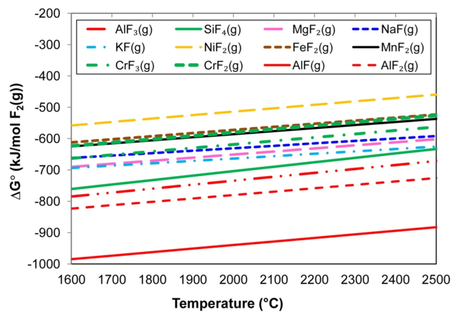
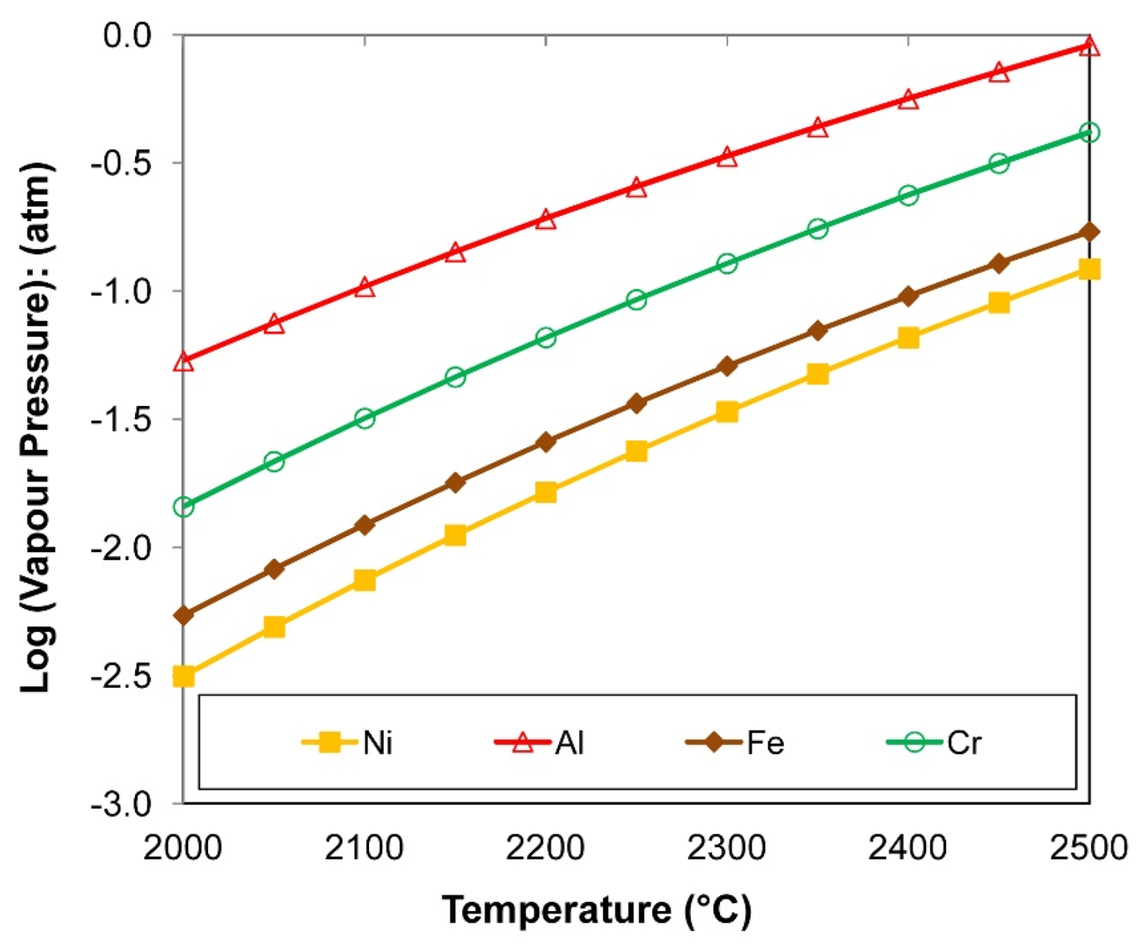
- At the high temperatures of the arc cavity, Cr and Ni in the form of metal vapour are thermodynamically favoured over NiF2(g), CrF2(g), and CrF3(g) formation because Al-fluorides are thermodynamically more stable. In addition, the low partial oxygen pressure (maintained by Al additions) prevents the oxidation of Cr and Ni.
- The application of unconstrained metal powders in SAW can improve overall process productivity because unconstrained metal powders can be directly applied in the SAW process, thus removing the need for the manufacturing of alloyed wire and alloyed powder as expensive time consuming steps.
Author Contributions
Funding
Data Availability Statement
Conflicts of Interest
References
- Sengupta, V.; Havrylov, D.; Mendex, P.F. Physical phenomena in the weld zone of submerged arc welding—A Review. Weld. J. 2019, 98, 283–313. [Google Scholar]
- Chai, C.S.; Eagar, T.W. Slag-metal equilibrium during submerged arc welding. Metall. Trans. B 1981, 12, 539–547. [Google Scholar] [CrossRef]
- Mitra, U.; Eagar, T.W. Slag-metal reactions during welding: Part I. Evaluation and reassessment of existing theories. Metall. Trans. B 1991, 22, 65–71. [Google Scholar] [CrossRef]
- Mitra, U.; Eagar, T.W. Slag-metal reactions during welding: Part II. Theory. Metall. Trans. B 1991, 22, 73–81. [Google Scholar] [CrossRef]
- Mitra, U.; Eagar, T.W. Slag-metal reactions during welding: Part III. Verification of the theory. Metall. Trans. B 1991, 22, 83–100. [Google Scholar] [CrossRef]
- Kluken, A.O.; Grong, Ø. Mechanisms of inclusion formation in Al-Ti-Si-Mn deoxidized steel weld metals. Metall. Trans. B 1989, 20, 1335–1349. [Google Scholar] [CrossRef]
- Chai, C.S.; Eagar, T.W. The effect of SAW parameters on weld metal chemistry. Weld. J. 1980, 59, 93–98. [Google Scholar]
- Singh, B.; Khan, Z.A.; Siddiquee, A.N. Effect of flux composition on element transfer during Submerged Arc Welding (SAW): A literature review. Int. J. Curr. Res. 2013, 5, 4181–4186. [Google Scholar]
- Palm, J.H. How fluxes determine the metallurgical properties of Submerged Arc Welds. Weld. J. 1972, 51, 358–360. [Google Scholar]
- Paniagua-Mercado, A.M.; Lopez-Hirata, V.M.; Saucedo Munoz, M.L. Influence of the chemical composition of flux on the microstructure and tensile properties of submerged-arc welds. J. Mater. Process. Technol. 2005, 169, 346–351. [Google Scholar] [CrossRef]
- Bang, K.; Park, C.; Jung, H.; Lee, J. Effects of flux composition on the element transfer and mechanical properties of weld metal in submerged arc welding. J. Met. Mater. Int. 2009, 15, 471–477. [Google Scholar] [CrossRef]
- Eagar, T.W. Sources of weld metal oxygen contamination during submerged arc welding. Weld. J. 1978, 57, 76–80. [Google Scholar]
- Tuliani, S.S.; Boniszewski, T.; Eaton, N.F. Notch toughness of commercial submerged arc weld metal. Weld. Met. Fabr. 1969, 37, 327–339. [Google Scholar]
- Dallam, C.B.; Liu, S.; Olson, D.L. Flux composition dependence of microstructure and toughness of submerged arc HSLA weldments. Weld. J. 1985, 64, 140–152. [Google Scholar]
- Chovet, A.; Galand, E.; Leduey, B. Effect of various factors on toughness in P92 SAW weld metal. Weld. World 2008, 52, 18–26. [Google Scholar] [CrossRef]
- Polar, A.; Indacochea, J.E.; Blander, M. Electrochemically generated oxygen contamination in submerged arc welding. Weld. J. 1990, 69, 68–74. [Google Scholar]
- Lau, T.; Weatherly, G.C.; Mc Lean, A. The sources of oxygen and nitrogen contamination in submerged arc welding using CaO-Al2O3 based fluxes. Weld. J. 1985, 64, 343–347. [Google Scholar]
- Chai, C.S.; Eagar, T.W. Slag metal reactions in binary CaF2-metal oxide welding fluxes. Weld. J. 1982, 61, 229–232. [Google Scholar]
- ESAB: Technical Handbook Submerged Arc Welding. 2021. Available online: https://assets.esab.com/asset-blank/assetfile/12295.pdf (accessed on 13 June 2021).
- O’Brien, A. Welding Handbook, Part 1, 9th ed.; American Welding Society (AWS): Miami, FL, USA, 2004. [Google Scholar]
- Hallén, H.; Johansson, K.-E. Use of a Metal Powder for Surface Coating by Submerged Arc Welding. U.S. Patent 6331688 B1, 18 December 2001. [Google Scholar]
- Mitra, U.; Eagar, T.W. Slag metal reactions during submerged arc welding of alloy steels. Metall. Trans. B 1984, 15, 217–227. [Google Scholar] [CrossRef]
- Burck, P.A.; Indacochea, J.E.; Olson, D.L. Effects of welding flux additions on 4340 steel weld metal composition. Weld. J. 1990, 69, 115–122. [Google Scholar]
- Lee, S.-B.; Choi, J.-H.; Jung, S.-M.; Lee, H.-G.; Rhee, P.C.-H. Aluminium deoxidation equilibrium on liquid Fe-16 Pct Cr alloy. Metall. Trans. B 2005, 36, 414–416. [Google Scholar] [CrossRef]
- Pramanik, S.; Suwas, S. Low-density steels: The effect of Al addition on microstructure and properties. JOM 2014, 66, 1868–1876. [Google Scholar] [CrossRef]
- Moon, J.; Ha, H.-Y.; Kim, K.-W.; Park, S.-J.; Lee, T.-H.; Kim, S.-D.; Jang, J.H.; Jo, H.-H.; Hong, H.-U.; Lee, B.H.; et al. A new class of lightweight, stainless steels with ultra-high strength and large ductility. Sci. Rep. 2020, 10, 12140. [Google Scholar] [CrossRef] [PubMed]
- Raabe, D.; Tasan, C.C.; Springer, H.; Bausch, M. From high-entropy alloys to high-entropy steels. Steel Res. Int. 2015, 86, 1127–1138. [Google Scholar] [CrossRef]
- Coetsee, T. Phase chemistry of Submerged Arc Welding (SAW) fluoride based slags. Mater. Res. Technol. 2020, 9, 9766–9776. [Google Scholar] [CrossRef]
- Coetsee, T.; Mostert, R.J.; Pistorius, P.G.H.; Pistorius, P.C. The effect of flux chemistry on element transfer in Submerged Arc Welding: Application of thermochemical modelling. Mater. Res. Technol. 2021, 11, 2021–2036. [Google Scholar] [CrossRef]
- Bale, C.W.; Bélisle, E.; Chartrand, P.; Decterov, S.; Eriksson, G.; Gheribi, A.E.; Hack, K.; Jung, I.-H.; Kang, Y.-B.; Melançon, J.; et al. Reprint of: FactSage thermochemical software and databases, 2010–2016. Calphad 2016, 55, 1–19. [Google Scholar] [CrossRef]
- Coetsee, T.; De Bruin, F.J. Improved titanium transfer in Submerged Arc Welding of carbon steel through aluminium addition. Miner. Process. Extr. Metall. Rev. 2021, 43, 771–774. [Google Scholar] [CrossRef]
- Coetsee, T.; De Bruin, F.J. Reactions at the molten flux-weld pool interface in submerged arc welding. High Temp. Mater. Processes. 2021, 40, 421–427. [Google Scholar] [CrossRef]
- Coetsee, T.; De Bruin, F. Application of Copper as Stabiliser in Aluminium Assisted Transfer of Titanium in Submerged Arc Welding of Carbon Steel. Processes 2021, 9, 1763. [Google Scholar] [CrossRef]
- Coetsee, T.; De Bruin, F. Chemical Interaction of Cr-Al-Cu Metal Powders in Aluminum-Assisted Transfer of Chromium in Submerged Arc Welding of Carbon Steel. Processes 2022, 10, 296. [Google Scholar] [CrossRef]
- Coetsee, T.; De Bruin, F. Aluminium-Assisted Alloying of Carbon Steel in Submerged Arc Welding: Application of Al-Cr-Ti-Cu Unconstrained Metal Powders. Processes 2022, 10, 452. [Google Scholar] [CrossRef]
- Coetsee, T.; De Bruin, F. Aluminium Assisted Nickel Alloying in Submerged Arc Welding of Carbon Steel: Application of Unconstrained Metal Powders. Appl. Sci. 2022, 12, 5392. [Google Scholar] [CrossRef]
- Coetsee, T.; De Bruin, F. Application of Unconstrained Cobalt and Aluminium Metal Powders in the Alloying of Carbon Steel in Submerged Arc Welding: Thermodynamic Analysis of Gas Reactions. Appl. Sci. 2022, 12, 8472. [Google Scholar] [CrossRef]
- Coetsee, T.; De Bruin, F. In Situ Modification of CaF2-SiO2-Al2O3-MgO Flux Applied in the Aluminium-Assisted Transfer of Titanium in the Submerged Arc Welding of Carbon Steel: Process Mineralogy and Thermochemical Analysis. Minerals 2022, 12, 604. [Google Scholar] [CrossRef]
- Gött, G.; Gericke, A.; Henkel, K.-M.; Uhrlandt, D. Optical and spectroscopic study of a submerged arc welding cavern. Weld. J. 2016, 95, 491–499. [Google Scholar]
| %C | %Si | %Mn | %O | %Al | %P | %S | %Ni | %Cr | %Fe | |
|---|---|---|---|---|---|---|---|---|---|---|
| Base Case | 0.110 | 0.260 | 1.300 | 0.0499 | 0.032 | 0.022 | 0.011 | 0.005 | 0.110 | 98.03 |
| MP8 | 0.098 | 0.560 | 1.637 | 0.0162 | 4.483 | 0.021 | 0.008 | 6.213 | 6.017 | 80.77 |
| %Si | %Mn | %Al | %Ni | %Cr | %Fe | |
|---|---|---|---|---|---|---|
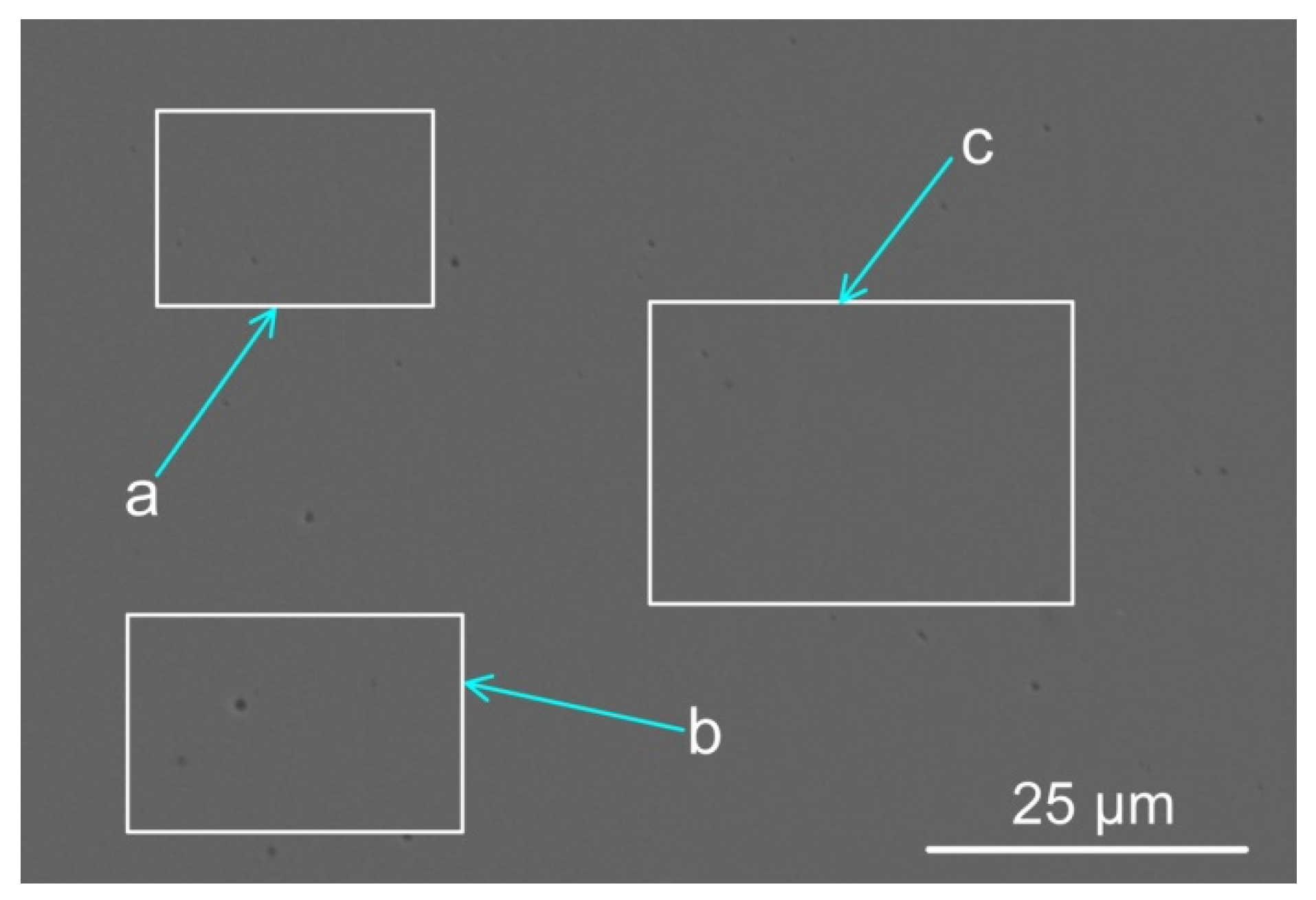
| a | 1.10 | 1.90 | 5.20 | 6.70 | 6.60 | 78.5 |
| b | 1.10 | 1.80 | 5.30 | 6.60 | 6.60 | 78.6 |
| c | 1.10 | 1.80 | 5.39 | 6.39 | 6.59 | 78.7 |
| Al (g) | Ni (g) | Cr (g) | Powder (g) | Wire (g) | Base Plate (g) | Weld Metal (g) | %DR(wire+MP) | %Al Yield | %Ni Yield | %Cr Yield | |
|---|---|---|---|---|---|---|---|---|---|---|---|
| Base Case | 0 | 0 | 0 | 0 | 33.8 | 33.8 | 67.6 | 50 | 0 | 0 | 0 |
| MP8 | 4.7 | 6.5 | 6.3 | 17.5 | 52.5 | 34.5 | 104.5 | 67 | 67 | 91 | 89 |
| SiO2 (g) | MnO (g) | Al (g) | Reaction (5) (kJ) | Reaction (6) (kJ) | Reactions (5) & (6) (kJ) | Weld Metal ΔT (°C) | |
|---|---|---|---|---|---|---|---|
| MP8 | 0.93 | 0.63 | 0.72 | −1.70 | −1.48 | −3.18 | 66 |
| Gram Al | %MgF2 | %MgF | %Mg | %AlF3 | %AlF2 | %AlF | %CaF2 | %NaF | %Na | %Mn | %MnF2 | %Ni | %Cr | %SiO |
|---|---|---|---|---|---|---|---|---|---|---|---|---|---|---|
| zero | 13 | 8 | 10 | 2 | 4 | 6 | 12 | 5 | 5 | 7 | 1 | 7 | 7 | 8 |
| 3.10 | 4 | 7 | 19 | 1 | 4 | 16 | 5 | 2 | 4 | 7 | <0.5 | 6 | 11 | 12 |
| 6.30 | 1 | 4 | 24 | <0.5 | 2 | 22 | 2 | 1 | 4 | 6 | <0.5 | 5 | 12 | 15 |
| Gram Al | Mass %Ni to Gas | Mass% Cr to Gas | Mass% Al to Gas | Po2 (atm) |
|---|---|---|---|---|
| zero | 11 | 12 | 0.0 | 1.3 × 10⁻⁶ |
| 3.10 | 15 | 26 | 57 | 2.4 × 10⁻⁷ |
| 6.30 | 19 | 40 | 50 | 7.1 × 10⁻⁸ |
Publisher’s Note: MDPI stays neutral with regard to jurisdictional claims in published maps and institutional affiliations. |
© 2022 by the authors. Licensee MDPI, Basel, Switzerland. This article is an open access article distributed under the terms and conditions of the Creative Commons Attribution (CC BY) license (https://creativecommons.org/licenses/by/4.0/).
Share and Cite
Coetsee, T.; De Bruin, F. Aluminium-Assisted Alloying of Carbon Steel in Submerged Arc Welding with Al-Cr-Ni Unconstrained Metal Powders: Thermodynamic Interpretation of Gas Reactions. Processes 2022, 10, 2265. https://doi.org/10.3390/pr10112265
Coetsee T, De Bruin F. Aluminium-Assisted Alloying of Carbon Steel in Submerged Arc Welding with Al-Cr-Ni Unconstrained Metal Powders: Thermodynamic Interpretation of Gas Reactions. Processes. 2022; 10(11):2265. https://doi.org/10.3390/pr10112265
Chicago/Turabian StyleCoetsee, Theresa, and Frederik De Bruin. 2022. "Aluminium-Assisted Alloying of Carbon Steel in Submerged Arc Welding with Al-Cr-Ni Unconstrained Metal Powders: Thermodynamic Interpretation of Gas Reactions" Processes 10, no. 11: 2265. https://doi.org/10.3390/pr10112265
APA StyleCoetsee, T., & De Bruin, F. (2022). Aluminium-Assisted Alloying of Carbon Steel in Submerged Arc Welding with Al-Cr-Ni Unconstrained Metal Powders: Thermodynamic Interpretation of Gas Reactions. Processes, 10(11), 2265. https://doi.org/10.3390/pr10112265